Selected Early Engines
Kemp, Kessler, King, Kirkham, Knox, Körting
Compiled by Kimble D. McCutcheon
Published 4 Aug 2022; Revised 8 Aug 2022
Kemp
The Kemp Machine Works, founded by George Kemp in Muncie, Indiana during 1905, built air-cooled engines for airplanes, motorcycles, air boats and ice boats.
|
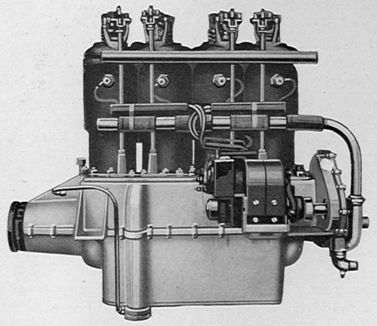
| Kemp I-4 (AEE) |
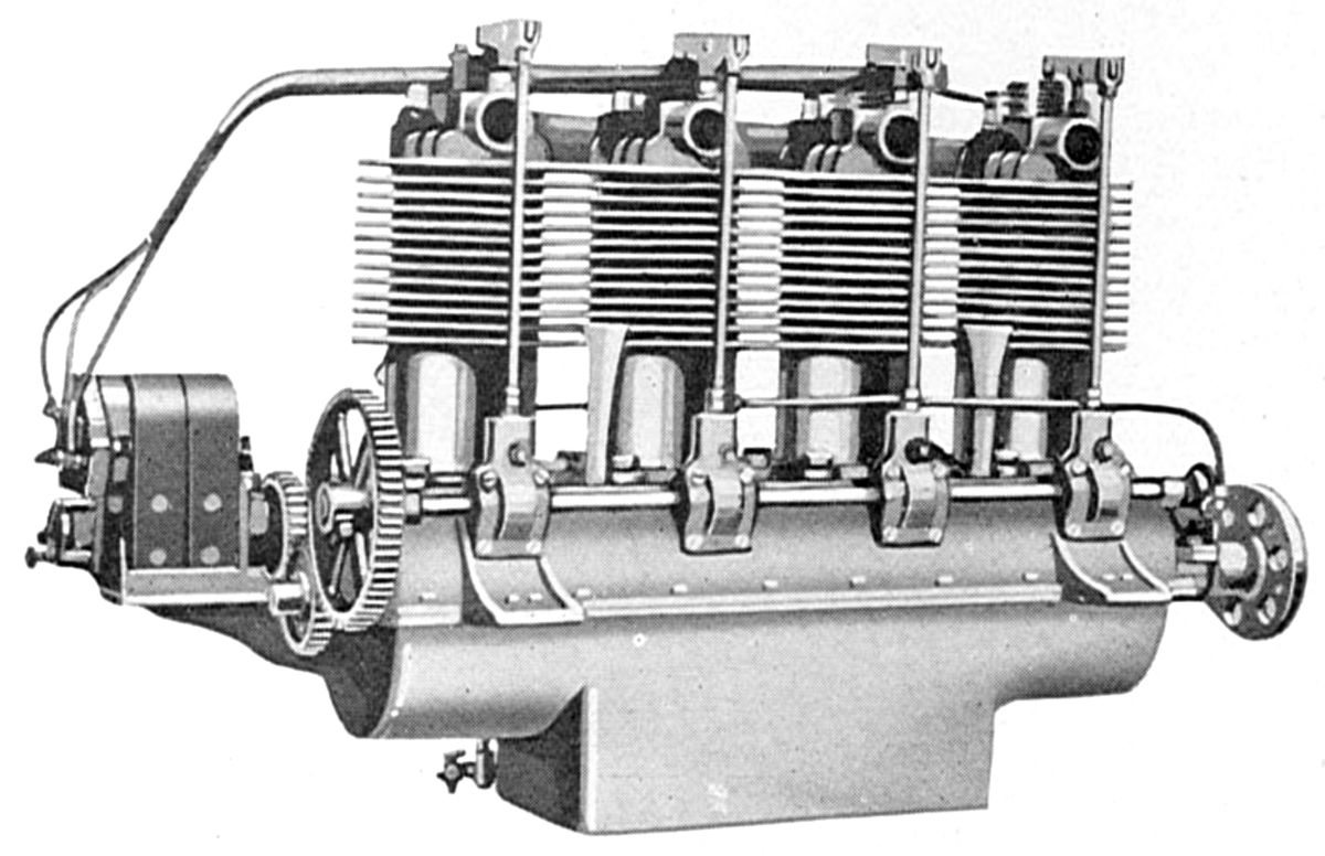
The Model I-4, introduced in 1911, was a vertical four with a 4.250" (107.95 mm) bore, 4.500" (114.30 mm) stroke and 255.35 in³ (4.18 l) displacement rated 35 hp at 1,150 rpm and weighing 192 lb, or 5.48 lb/hp. The nickel-plated machined-all-over steel cylinders had vertical concentric valves, the inlet operating automatically within the push-rod-and-rocker-arm actuated exhaust valve. In addition, the cylinders had eight exhaust openings near their bottoms that were uncovered by the pistons near bottom center. Note: these do not appear in the I-4 image but ARE visible in the linked reference article. The camshaft was a long tube with cams pinned in place along its length, all driven by an exposed gear train at its aft end. The I-4 used a five-main-bearing crankshaft cut from a steel slab after which main and crankpin journals were turned and ground. H-shank connecting rods were cast from bronze with poured Babbitt bearings reamed to size. Pistons were ribbed cast-iron with two rings, which had been shot-peened and ground, making their tension uniform and allowing groove clearances as small as 0.005", which helped prevent carbon accumulation and sticking. The crankcase was cast aluminum alloy. The lubrication system pumped oil from a crankcase sump to the crankcase main bearings and to crankcase compartments into which the connecting rods dipped. Crankshaft thrust bearings resolved thrust loads in either direction. Schebler carburetors and Mea magnetos were standard equipment.
|
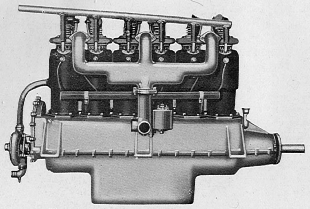
| Kemp H-6 (AEE) |
The Model H-6, a vertical six that used I-4 cylinders, displaced 383.03 in³ (6.277 l) and was rated 55 hp at 1,150 rpm. Weight was 272 lb, or 4.94 lb/hp. The H-6 used a seven-main-bearing crankshaft.
 |
.jpg) |
| Shrouded, Bare (AEE, Otto Sellers) | |
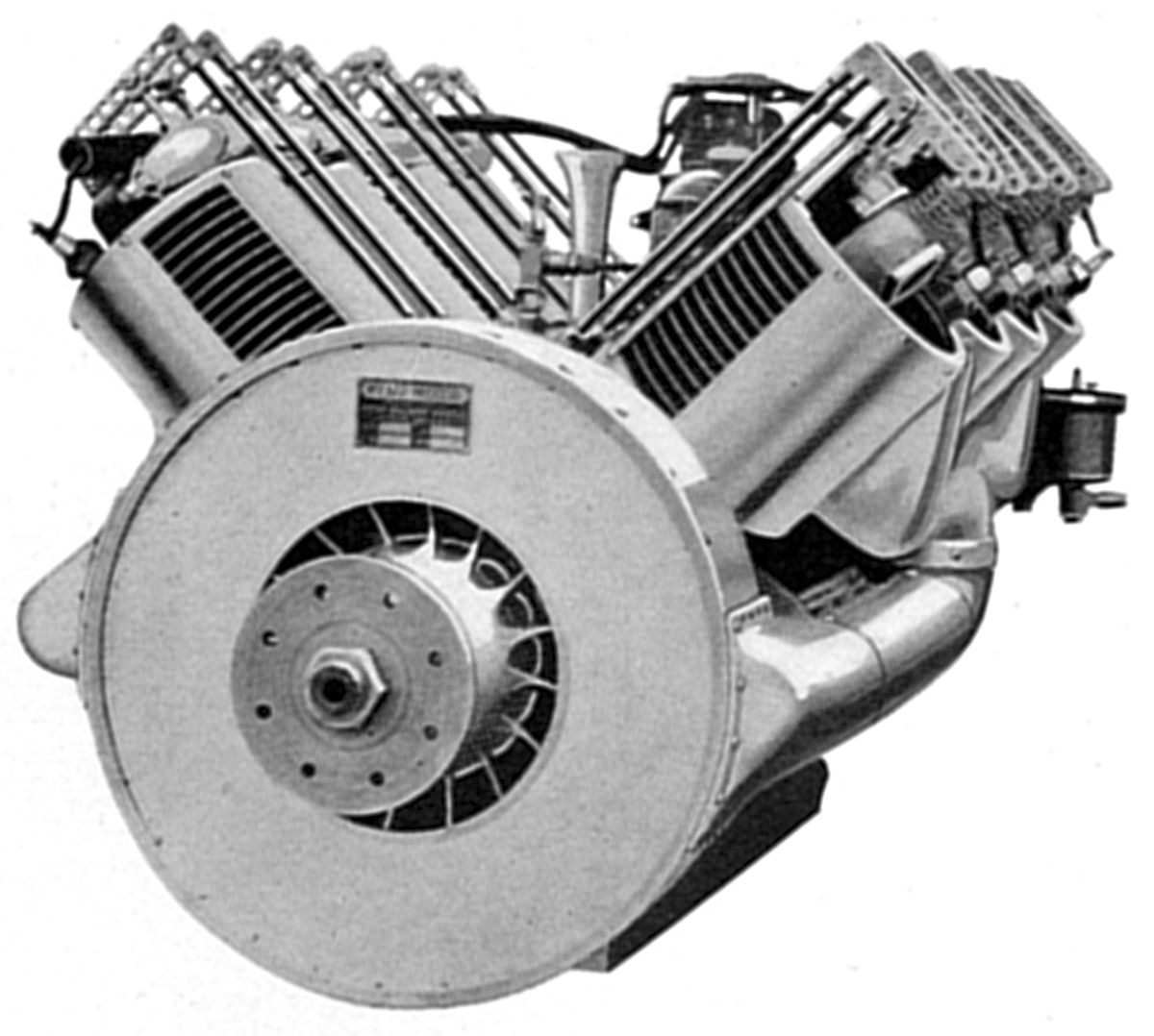
The Model J-8, an air-cooled V-8 with a 4.250" (107.95 mm) bore, 4.750" 120.65 mm) stroke and 539.08 in³ displacement introduced in 1914, was rated 80 hp at 1,150 rpm and weighed 380 lb, or 4.33 lb/hp. The J-8 had a new cylinder design featuring vertical inlet and exhaust valves operated by push rods and rockers; the auxiliary exhaust ports were eliminated. A five-main-bearing crankshaft. Aluminum bronze connecting rods had H-section shanks with an additional center rib. The positive forced-draft cooling system consisted of a crankshaft-mounted fan just aft of the propeller hub that discharged air into two plenums feeding cooling shrouds that partially surrounded the cylinders. A BH-8 Mea magneto was standard ignition equipment, and either Zenith or Schebler Model L carburetors were available.
Kemp ceased producing aircraft engines in 1917 due to material scarcity during WWI. When the war ended, cheap war-surplus OX-5s flooded the market.
Kemp Reference
Escallon, Ed "The Kemp Air-Cooled Aeroplane Motors", The Vintage Airplane (Hales Corners, Wisconsin: EAA Antique/Classic Division, Inc. , March 1980 Vol. 8 No. 3, pp 12 – 15).
Kessler
Beginning 31 Aug 1907, Martin C. Kessler filed several patents (US 1,221,544, US 1,221,545, US 1,070,139, US 1,012,652, US 1,477,362, US 1,477,363) describing a scheme to supercharge four-stroke engines by using closed crankcase chambers as air pumps that supplied air to the cylinders through ports uncovered by the piston crowns near bottom center. A rotary valve whose open duration was controlled by the engine throttle governed the process. This helped scavenge exhaust gasses and also helped improve efficiency in the relatively low compression ratio engines of the day by increasing the working fluid pressure. This idea fell out of favor as engine compression ratios rose since the minimal pressure increase from crankcase compression contributed less and less to the working fluid pressure.
Kessler founded the Kessler Motor Company of Detroit, Michigan in 1917. Kessler Motor Company supplied these ‘Super-Charge’ engines to various automobile builders and also built an automobile of its own design around the engine. During WWI, the U. S. Army and Navy became jointly interested in developing a water-cooled supercharged vertical six for aircraft use that was based on the Kessler concept. Although this engine never saw widespread use, it is noteworthy as one of many technological dead ends from aircraft engine infancy.
 |
 |
| 200 hp (AEE) | 6C-400 (AEE) |
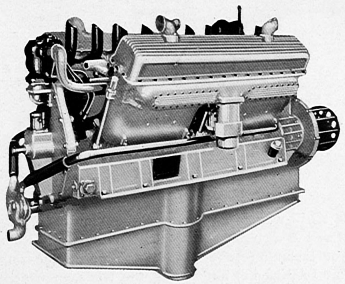
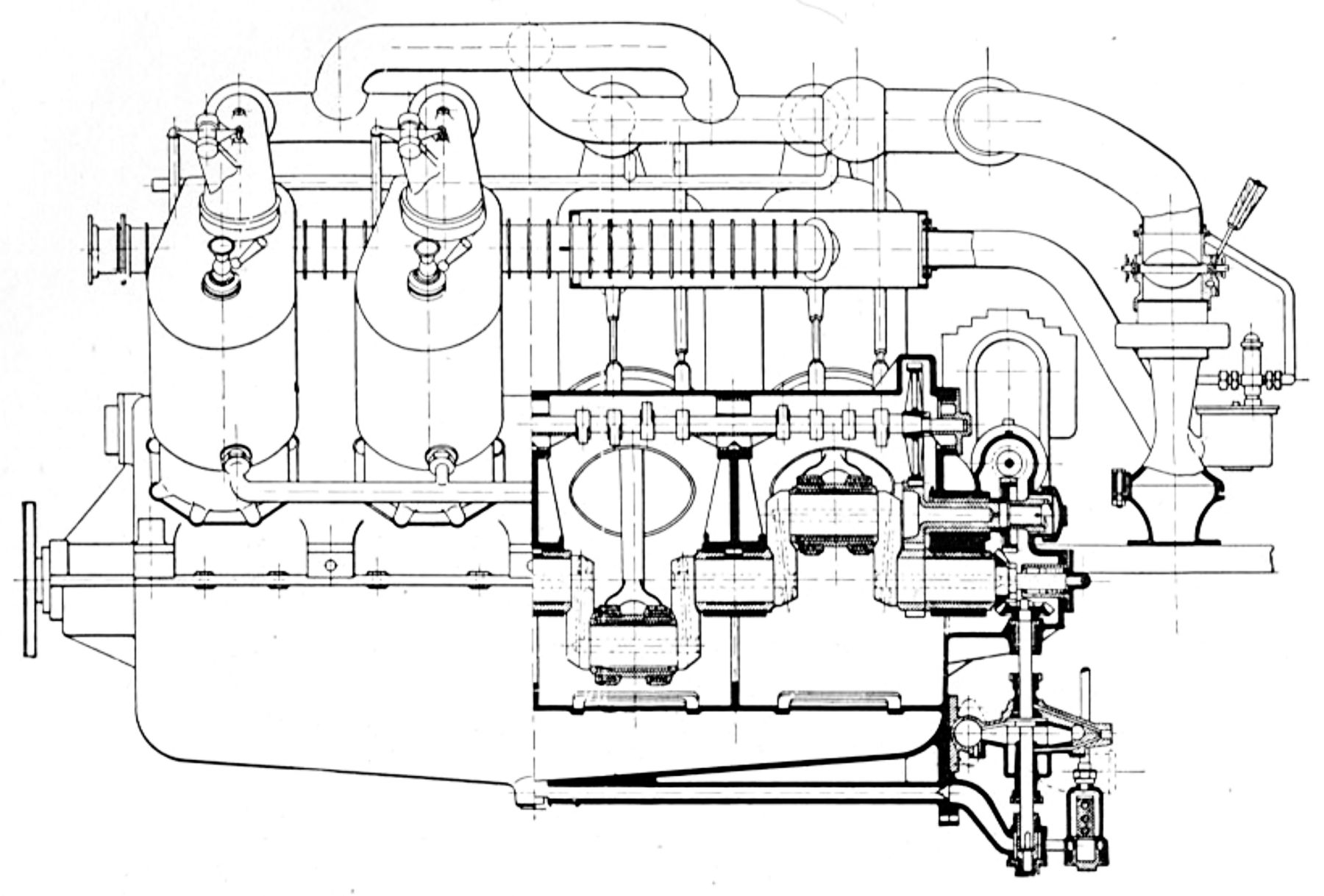
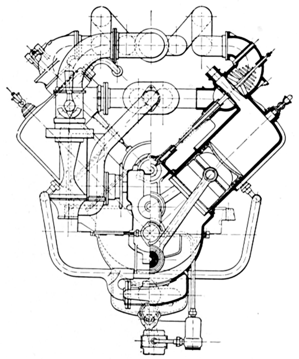
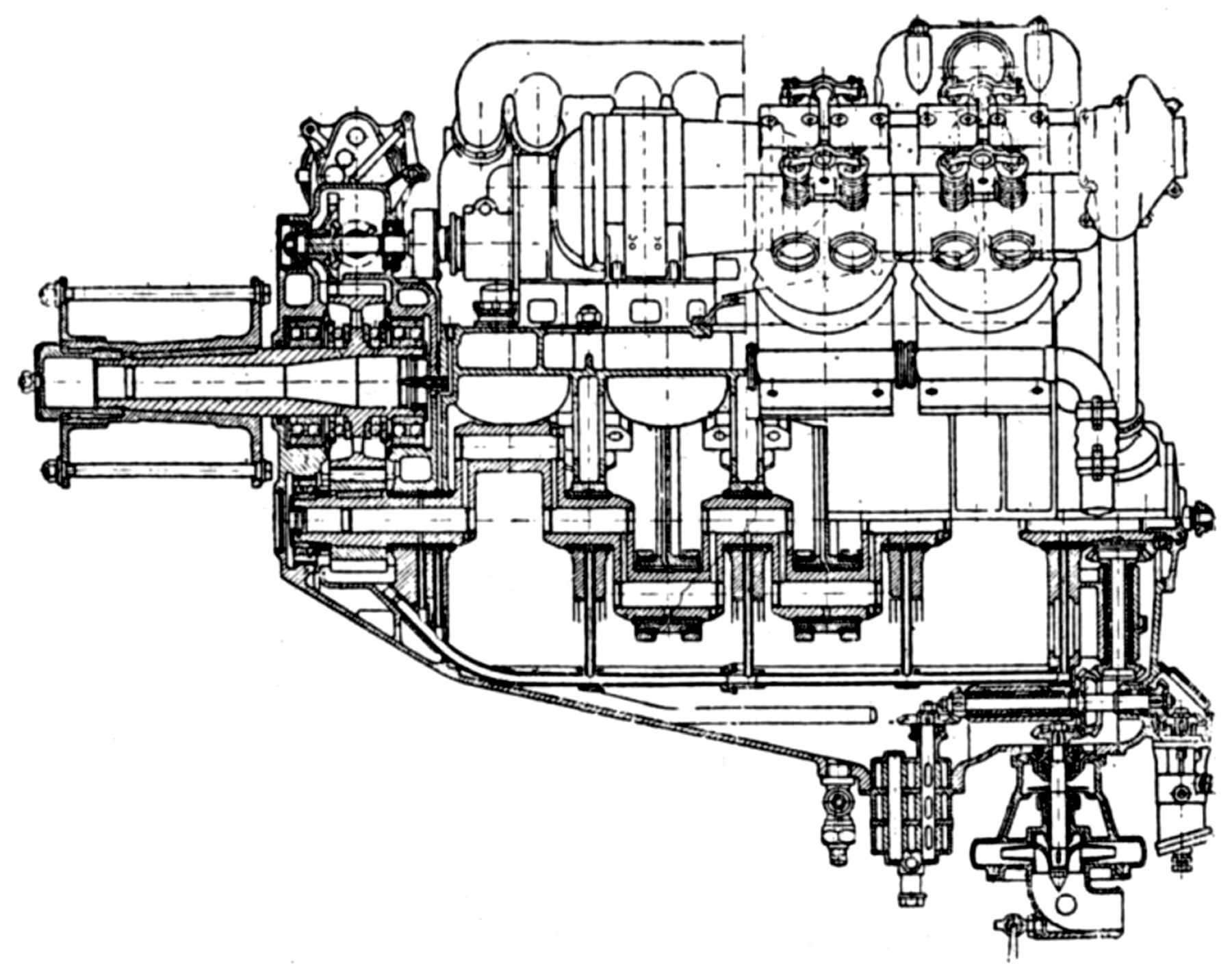
The geared engine Kessler provided to the U.S. Military had a 4.750" (120.65 mm) bore, 5.00" (127.00 mm) stroke, 531.62 in³ (8.712 l) displacement and produced 200 hp at 2,400 rpm. The cylinders and water jackets were cast en bloc. A single overhead camshaft operated four valves in each cylinder through offset vee-shaped rocker arms that pivoted on either side and employed a mushroom cam follower. The camshaft was driven through a spur gear train. The crankshaft was counterbalanced, the connecting rods had H-section shanks and two-bolt caps, and the unusual pistons had open skirts except for those portions required for thrust purposes.
Kessler also experimented with a six-valve-per-cylinder engine, the Model 6C-400, which had a 5.500" (139.70 mm) bore, 6.000" (152.4 mm) stroke, 855.30 in³ (14.016 l) displacement and weighed 578 lb.
King (see Bugatti)
Kirkham
 |
 |
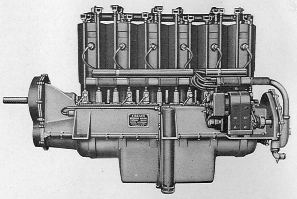 |
| B-4 (AEE) | B-6 (AEE) | B-G-6 (AEE) |
Charles B. Kirkham (1882 – 1969), like many early aviation enthusiasts, was initially drawn to bicycles and motorcycles. Kirkham and Glenn Curtiss supplied a modified motorcycle engine to Thomas C. Benbow in 1903 for an early airship. Kirkham founded Kirkham Motor and Manufacturing Company in Bath, New York during 1905 and in 1910 introduced the B-4, the first aircraft engine of his own design. Kirkham began working for the Curtiss Aeroplane and Motor Corporation in 1915 as its chief engine designer where he was responsible for the V2, K-6 and K-12 models. Kirkham left Curtiss in 1919 to form Kirkham Products.
Early Kirkham engine cylinders were cast separately from gray iron with integral water jackets. Their hemispherical combustion chambers featured two pockets for the spark plug bosses. Concentric valves were operated via concentric push rods and rockers from a camshaft within the crankcase. The pistons, also cast of grey iron, were fitted with two top rings. The piston pin was locked in the connecting rod upper end. The H-section connecting rods shanks had their webs drilled for lightness. All Kirkham crankshafts had Parsons white brass main bearings on either side of a crank throw. Manganese bronze main bearing caps were secured by two studs.
The Model B-4, a water-cooled vertical four with a 4.125" (104.78 mm) bore, 4.75" (120.65 mm) and 253.92 in³ (4.161 l) displacement, was rated 35 – 40 hp at 1,400 rpm. Weight was 80 lb, or 4.5 lb/hp. The inlet valve diameter was 2", the exhaust valve diameter was 2.375", and both had a 0.3125" lift.
The Model B-6, which used six B-4 cylinders for a 380.88 in³ (6.241 l) displacement, developed 74.5 hp at 1,300 rpm and weighed 235 lb.
The Model B-G-6, a water-cooled vertical six with a 1.75:1 propeller reduction ratio, 4.3125" (109.54 mm) bore, 5.125" (130.18 mm) and 449.15 in³ (7.360 l) displacement was rated 70 hp at 1,680 rpm.
A water-cooled vertical four based on B-G-6 components and displacing 299.43 in³ (4.907 l) was rated 50 hp at 1,350 rpm and weighed 190 lb, or 3.8 lb/hp.
Knox
 |
 |
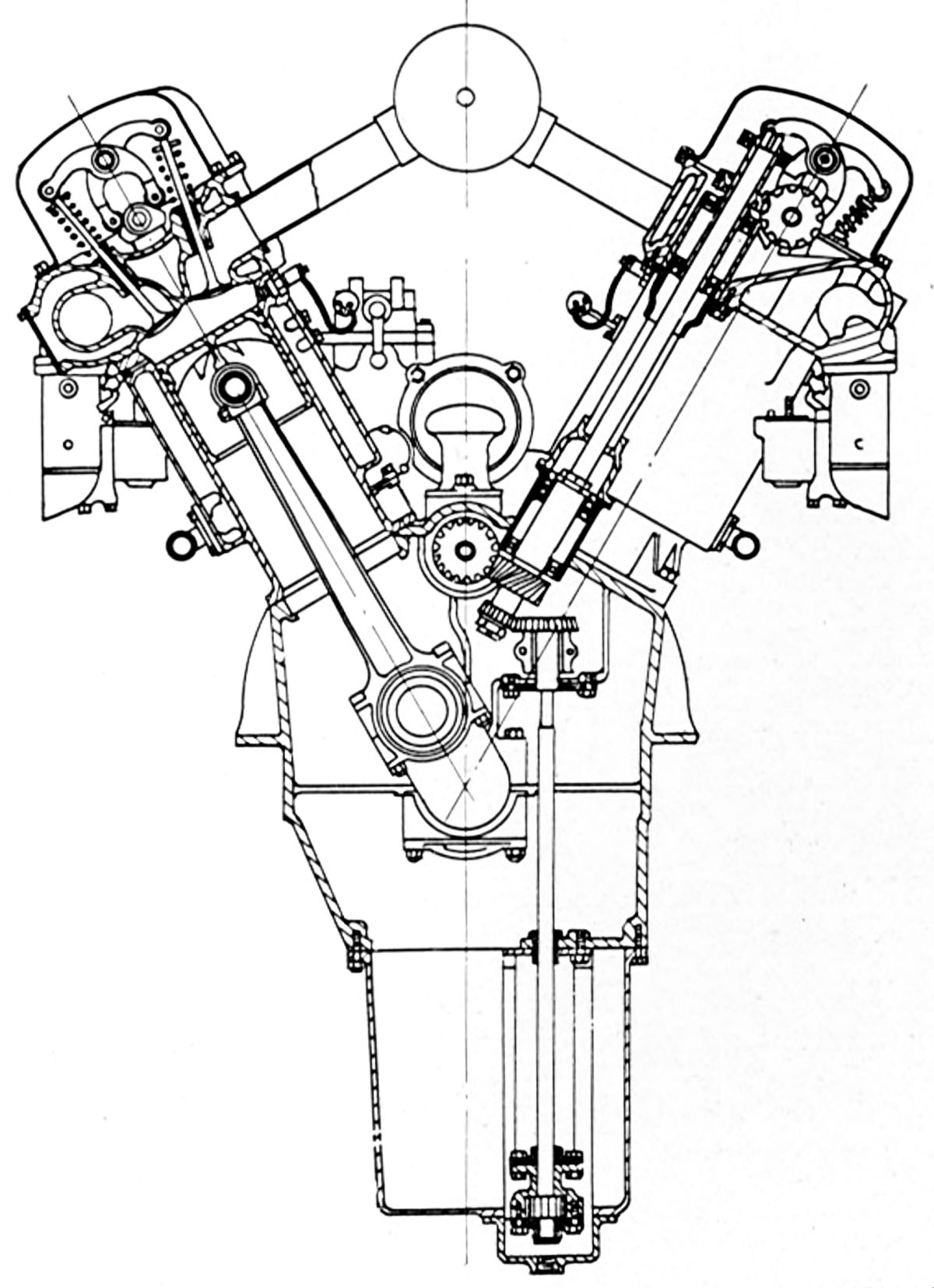
| Knox 300 hp V-12 (AEE) | |
During 1916, the Knox Motors Corporation of Springfield , Massachusetts, which was the reorganized Knox Automobile Company and which now built tractors and trucks, introduced a geared water-cooled 60° V-12 aircraft engine. With a 4.750" (120.65 mm) bore, 7.000" (177.80 mm) stroke and 1488.53 in³ (24.393 l) displacement, it was rated 300 hp at 1,600 rpm and weighed 1,400 lb. Aluminum alloy cylinders were cast in blocks of three and 0.125"-wall cast iron cylinder liners were pressed in from the bottom. Aluminum alloy cylinder heads were in blocks of six with cast-iron valve seats cast permanently in place. Sixteen studs passing through the head captured the head and cylinders. Four slightly inclined valves in each cylinder were operated via rocker arms from a single overhead camshaft carried in eight bearings. The rocker arms were supported above the camshaft, and the entire valve mechanism was completely enclosed by an oil-tight aluminum cover. The crankshaft ran three large plain bearings. At the engine center, just above the crankshaft and driven by the timing gears, was a horizontal driveshaft with two integral spiral gears driving two vertical shafts with integral gears that passed up through tubes into the cylinder head. Each vertical shaft extended on through a hollow short shaft and finally terminated in a splined end that received a splined cap piece that was bolted to the short hollow shaft to fix the relative camshaft and vertical drive shaft positions for timing purposes. Oil draining from above the cylinder head returned to the crankcase via these tubes. The aluminum alloy pistons had three rings and the piston pin was clamped in the connecting rod upper end. The H-section connecting rods with two-bolt caps were arranged side by side on each crank-pin. The propeller shaft was supported in double-row ball bearings, and carried a double-ball thrust hearing to take thrust loads in either direction. The starting gear, which was attached to the propeller shaft, was connected to the starting motor through a train of gears and a special roller clutch.
Körting
Brothers Ernst and Berthold Körting founded the Gebrüder Körting (Körting Brothers) company on 1 Nov 1871 in Hannover, Germany to develop and sell Ernst's newly-invented steam jet boiler feed pumps and other firing technology. The company thrived and despite being demolished by Allied bombing in 1945, continues to operate as Körting Hannover AG, the Ejector Company, and is still owned by the fifth generation Körting family. It produces ejectors, vacuum technology, waste gas cleaning, environmental technology, process heat technology and firing technology.
 |
 |
| Körting 8 SL 116 (AEE) | |
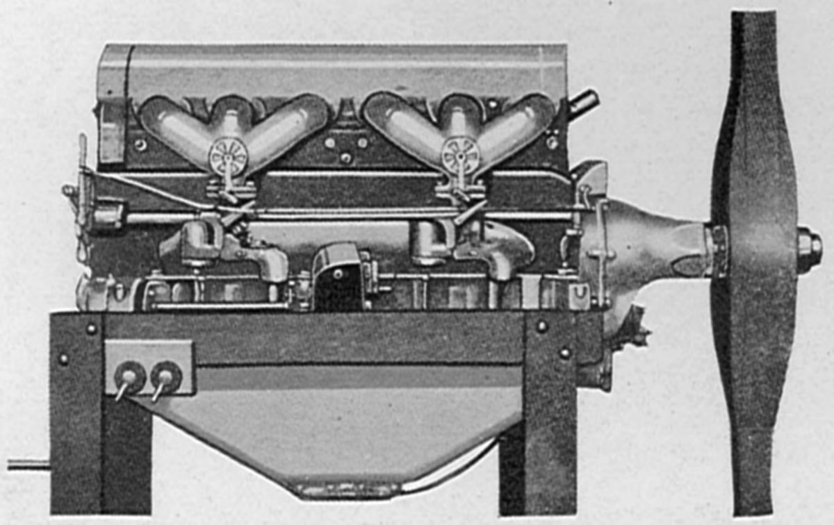
In 1906, Körting built the 8 SL 116, a water-cooled 90° V-8 intended to power airships. With a 116 mm (4.567") bore, 126 mm (4.961") stroke, 10.653 l (650.09 in³) displacement and 440 lb weight, it developed 65 hp at 1,250 rpm and 72 hp at 1,400 rpm. Fuel and oil consumptions 0.66 and 0.044 lb/hp/hr. The F-head cylinders with welded steel water jackets had inlet valves directly over the exhaust. The inlet valves were operated through push rods and rockers, while the exhaust valves were actuated by tappets from a central camshaft in the Vee. The four-throw crankshaft was supported in five plain main bearings, and the fork-and-blade connecting rods had tubular shanks. Magnetos supplied ignition.
 |
| Körting Kg III (A39) |
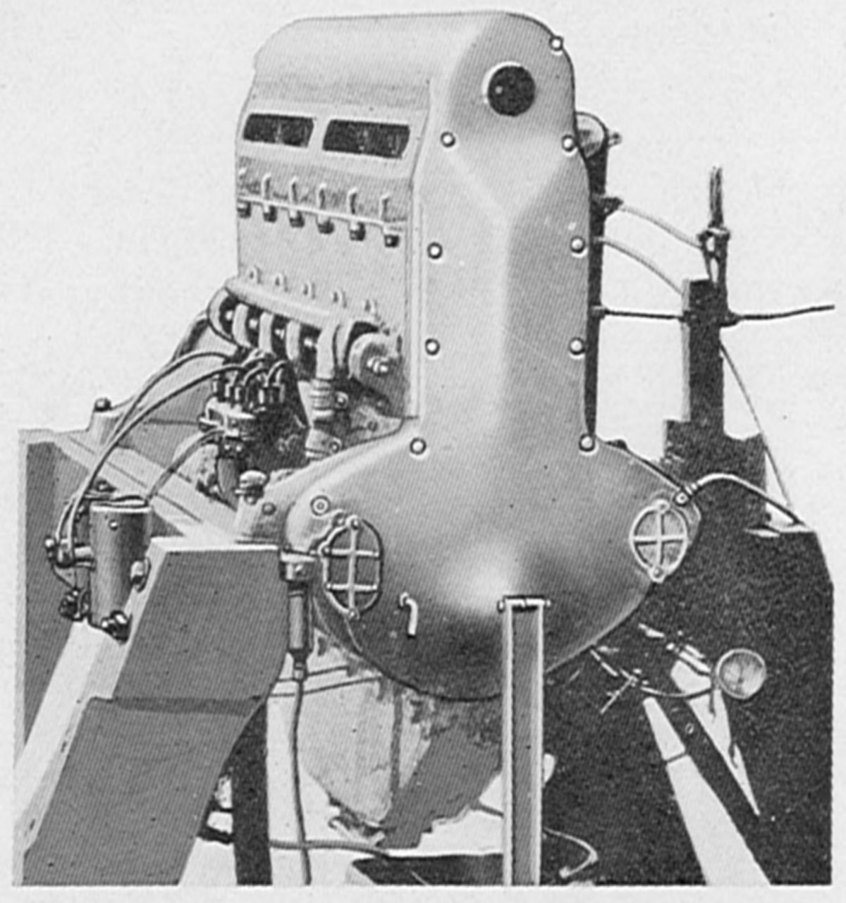
The Kg III, a 1916 water-cooled 90° V-8 with a 110 mm (4.331") bore, 140 mm (5.512") stroke, 10.644 l (649.54 in³) displacement, 4.9:1 compression ratio and 2:1 spur propeller reduction gearing, was rated 185 hp at 2,150 rpm. Fuel consumption was 0.547 lb/hp/hr and total weight was 556 lb, or 3 lb/hp. The four valves in each cylinder were operated by overhead camshafts. Forked-and-blade connecting rods with H-section shanks had clamped-on tubes that delivered oil to the piston pin bearing.
 |
| Körting Kg IV (AEE) |
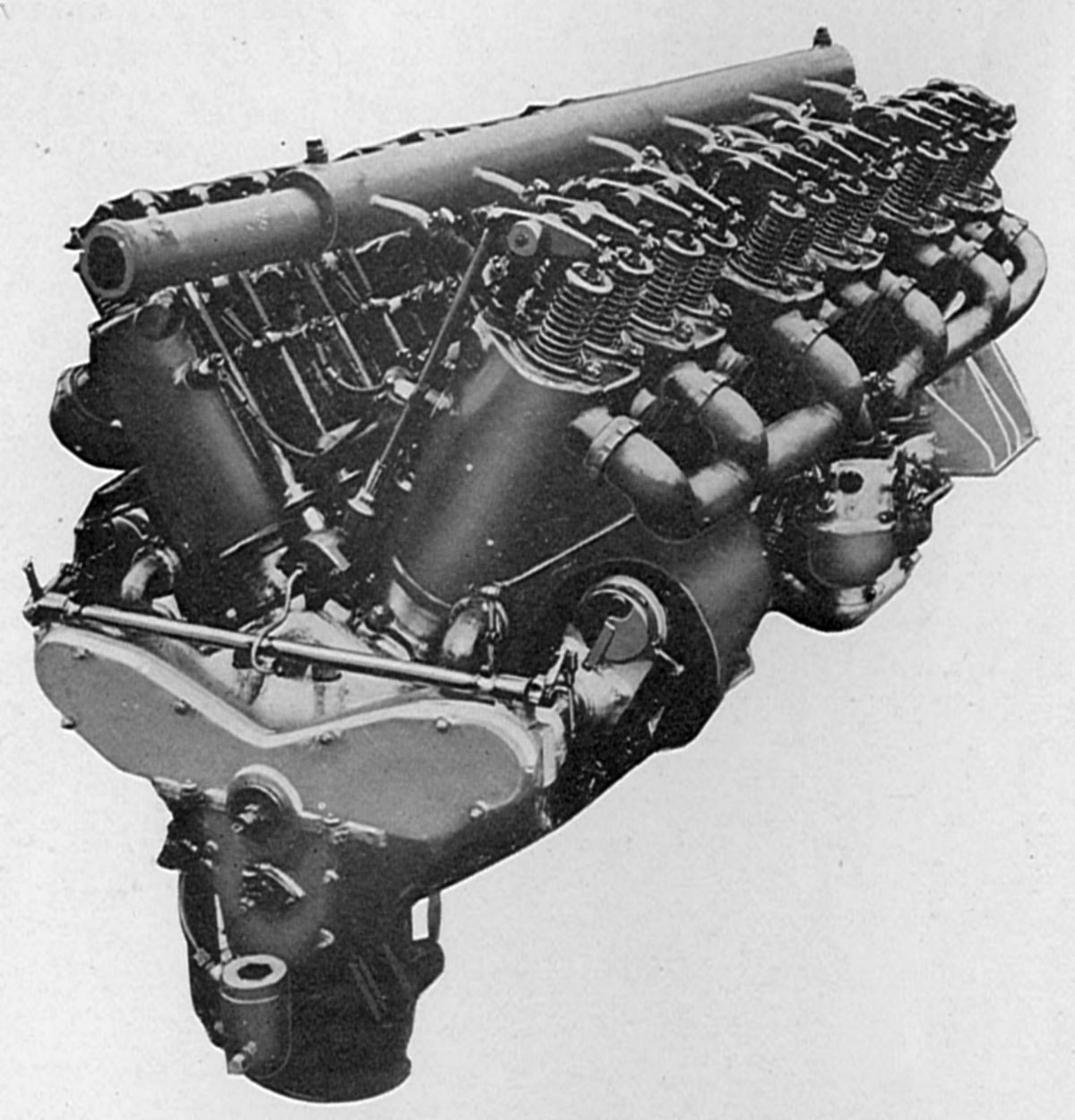
The Kg IV, a 1918 water-cooled 60° V-12 with a 120 mm (4.724") bore, 140 mm (5.512") stroke, 19.000 l (1,159.45 in³) displacement and 4.52:1 compression ratio, was rated 250 hp at 1,350 rpm, but demonstrated 252.5 hp at 1,360 rpm and 262 hp at 1,750 rpm. Weight was 992 lb, or 3.91 lb/hp. The individual steel cylinders had welded-on sheet-metal water jackets. The inlet and exhaust valves were aligned with the cylinder bank the longitudinal axis and were operated through push rods and rocker arms from a camshaft mounted in its own separate housing within the Vee. The crankshaft had four main bearings and fork-and-blade connecting rods. Herringbone reduction gears drove a propeller shaft mounted on ball-bearings within a gear housing split along the horizontal. Two carburetors mounted outside each cylinder bank fed three cylinders each. Two 12-cylinder B.T.H. A.V.12 high tension magnetos, driven by a spring coupling, supplied two spark plugs per cylinder. Both electric and hand starters were fitted. Cooling water was circulated by a centrifugal pump. The spark advance mechanism was coupled with the air intake control.
References
Angle, Glenn D, ed. Aerosphere 1939 (New York, New York: Aircraft Publications, 1940).
Anble, Glenn D, ed. Airplane Engine Encyclopedia (Dayton, Ohio: Otterbein Press, 1921).
Image Sources: A39 = Aerosphere 1939; AEE = Airplane Engine Encyclopedia; Flt = Flight Magazine; NARA = U.S. National Archives and Records Administration; UKNA = United Kingdom National Archives.
Send mail to
![]() with questions or comments about this web site.
with questions or comments about this web site.
![]()