Selected Early Engines
Beardmore, Bentley, Benz, BMW, Bristol, Bugatti
Compiled by Kimble D. McCutcheon
Published 11 Mar 2022; Revised 1 May 2022
Beardmore
Early Beardmore engines were refined Austro-Dainiler designs, which at one time were thought the most efficient airplane engines in existence. Arrol ]ohnston and William Beardmore and Co. were the best known among the several firms that constructed Beardmore engines and parts. Prior to 1916, 90 and 120-hp models were built; afterward, larger engines were needed. Arrol Johnston, Ltd., of Dumfries, Scotland, (a Beardmore Associated concern) developed and later manufactured the 160-hp Beardmore. Although not an exact copy of any Austro-Daimler model, the 160-hp Beardmore still retained the principal features and the same general form. William Beardmore & Co., Ltd. of Parkhead Steel Works, Glasgow, Scotland also developed the B.H.P. Siddeley Puma engines. Aircraft engine development activities flagged following WWI until about 1923, when the firm-began working on large inline water-cooled six-cylinder engines. Little was known of the exact nature of these activities until 1926, when two models appeared. Beardmore built both gasoline and Diesel engines.
As with the Austro-Daimler from which this first design originated, the 90 hp Beardmore bore was 120 mm (4.724"), stroke was 140 mm (5.512"), displacement was 9.5 l (579.7in³) and it made rated power at 1,300 rpm. Six separate vertical water-cooled cylinders' fuel consumption was 0.54 lb/hp/hr and oil consumption .028 lb/hp/hr.
The 120 hp Beardmore, another six-cylinder vertical water-cooled engine with a 130 mm (5.118") bore, 175 mm (6.890") stroke, and a 13.937 l (850.5 in³) produced up to 135 hp at 1,200 rpm. Fuel consumption was 0.54 lb/hp/hr and oil consumption was 0.028 lb/hp/hr. The cylinders were offset 18 mm (0.709") from the crankshaft centerline in the direction of crankshaft rotation to help reduce piston side loads. The cast-iron cylinders were secured with steel flanges and featured electrolytically-deposited copper water jackets. Both valves were operated by one pushrod, and were held to their seats by laminated leaf springs, a feature of all early Beardmore engines. The exhaust valve seated in the cylinder proper, while the inlet valve seated in a removable valve cage. The inlet valve opened 27.5° late and closed 37° late; the exhaust valve opened 41° early and closed 2.5° early. The six-throw crankshaft on nine plain bearings. The H-shank connecting rods had four-bolt caps. The steel pistons were fitted with three rings. Mixture was furnished by two Beardmore carburetors feeding three cylinders each. A Bosch six-plunger lubricator forced oil to the main bearings, while the connecting rod big ends were splash lubricated. A centrifugal pump circulated cooling water while two H-L-6 magnetos supplied dual ignition. Dry weight was 545 lb.
|
|
|
| Beardmore 160 hp Engine (NARA) | ||
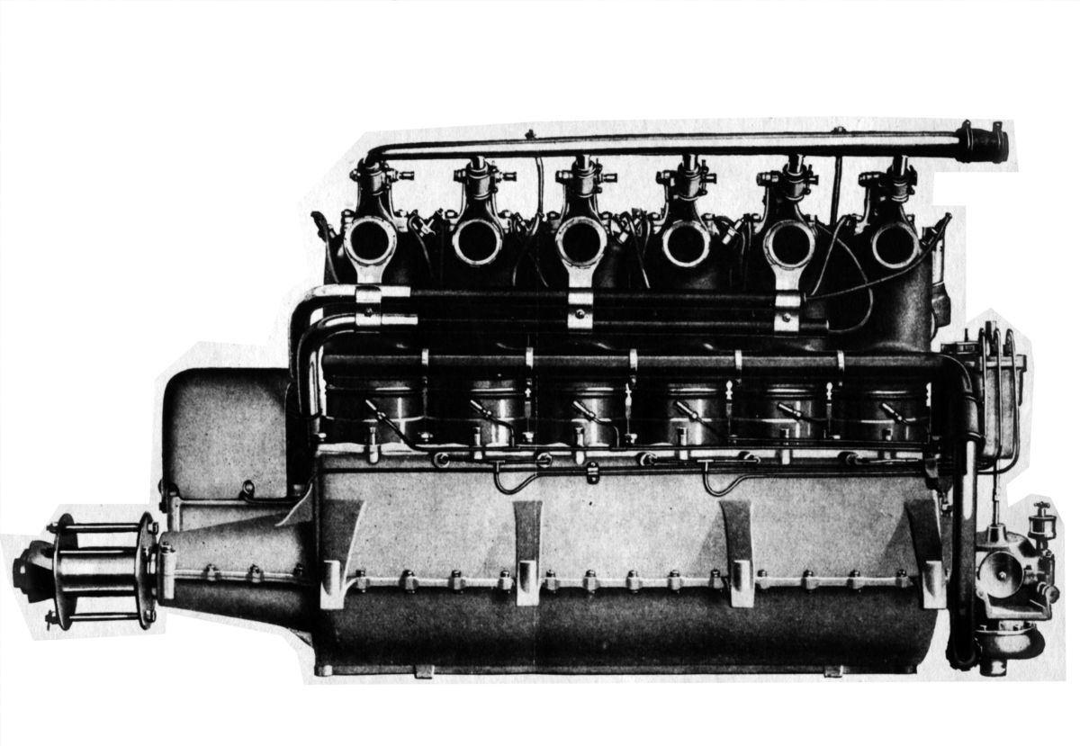
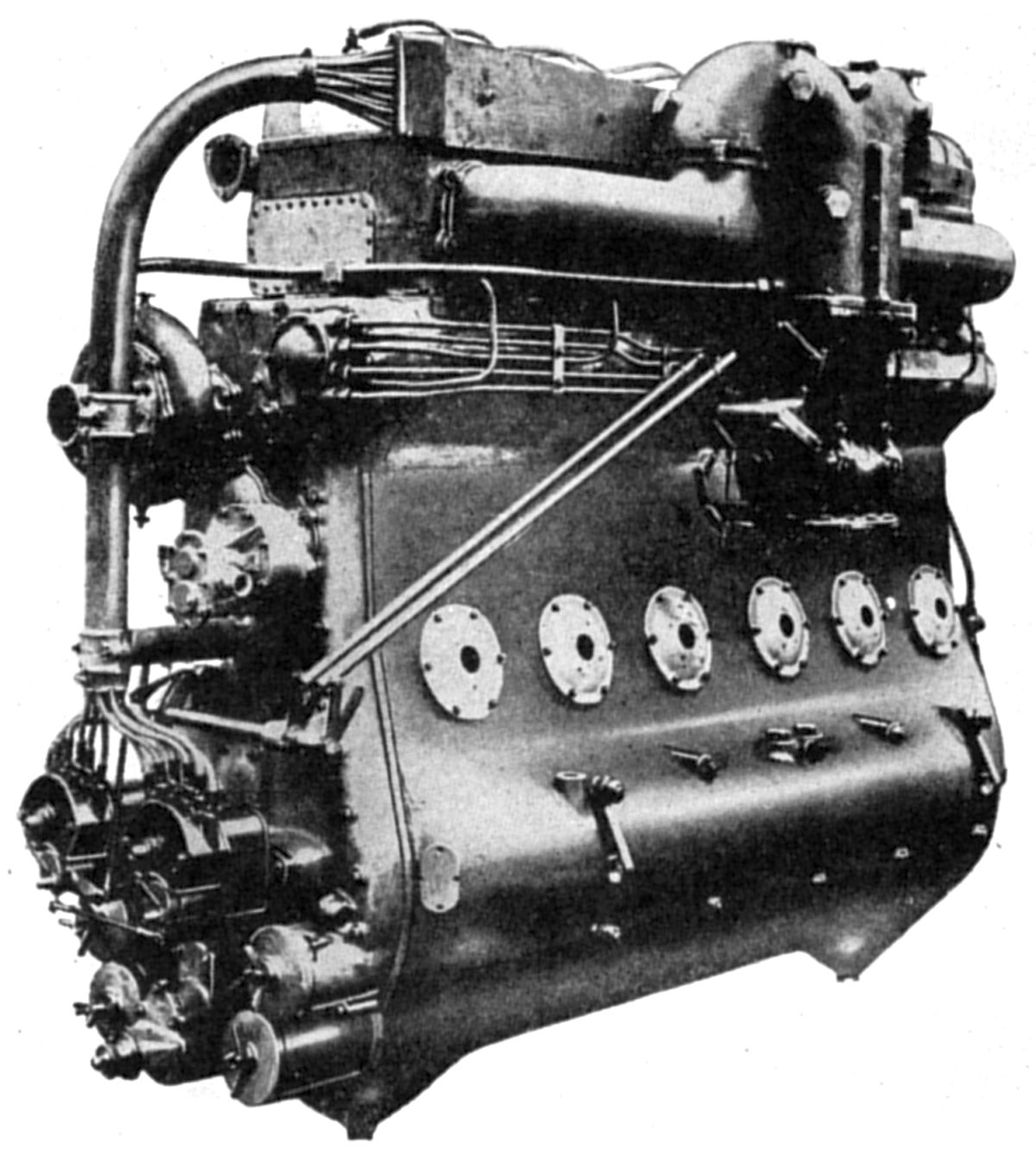
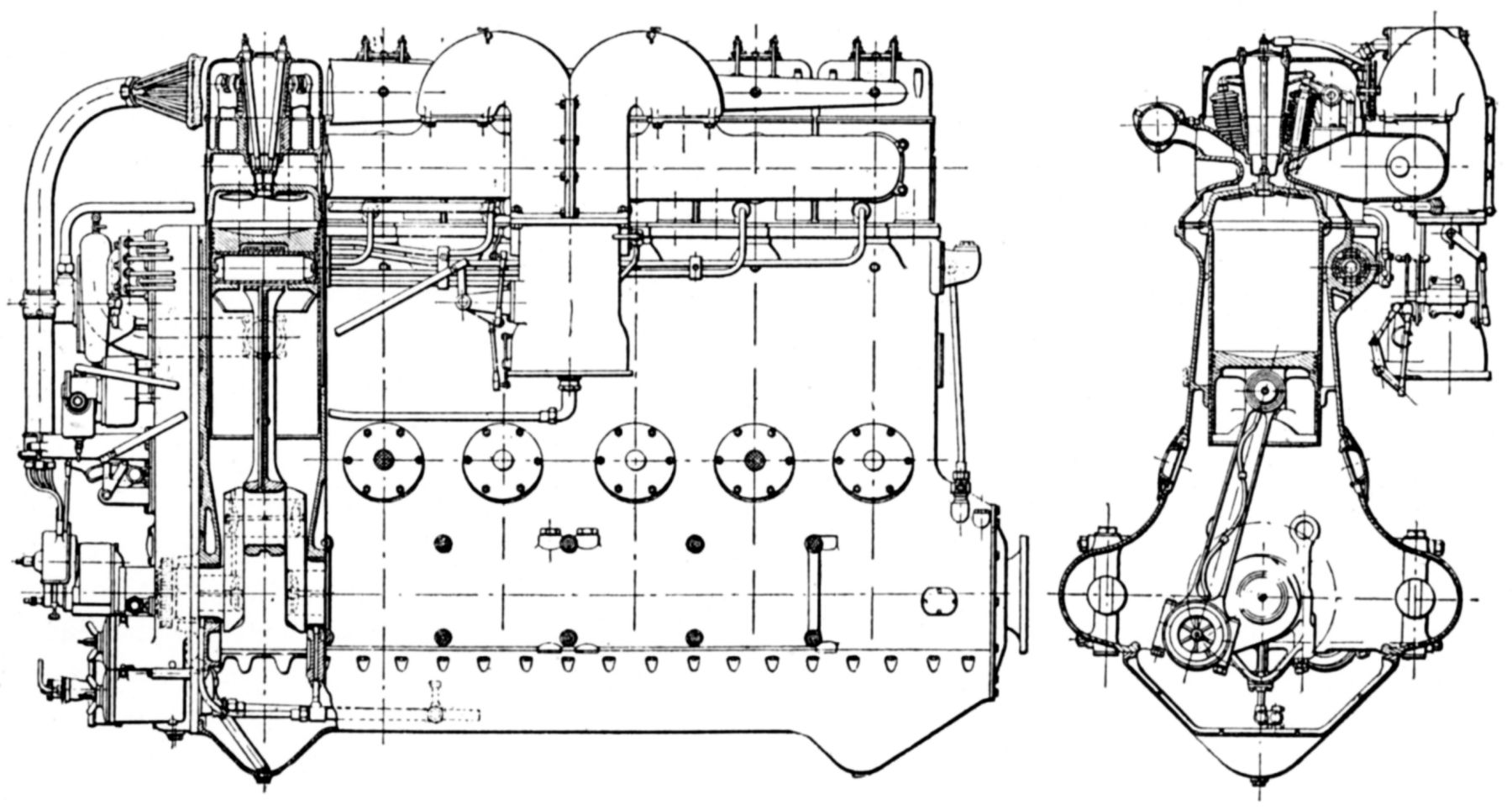
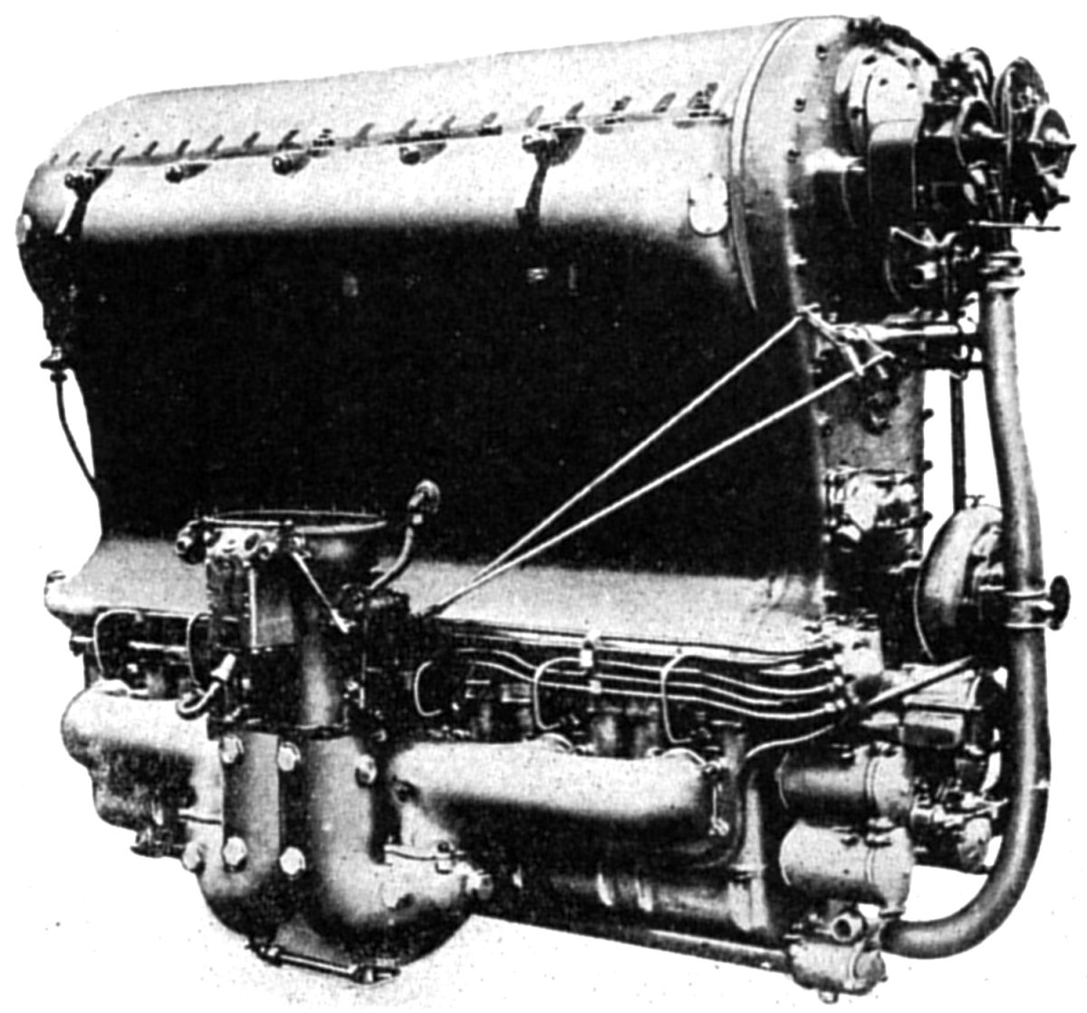
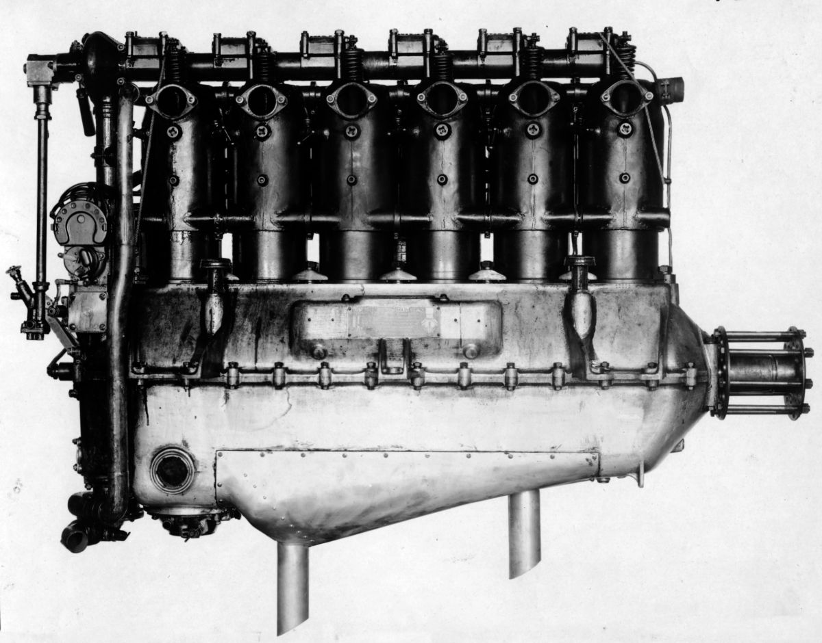
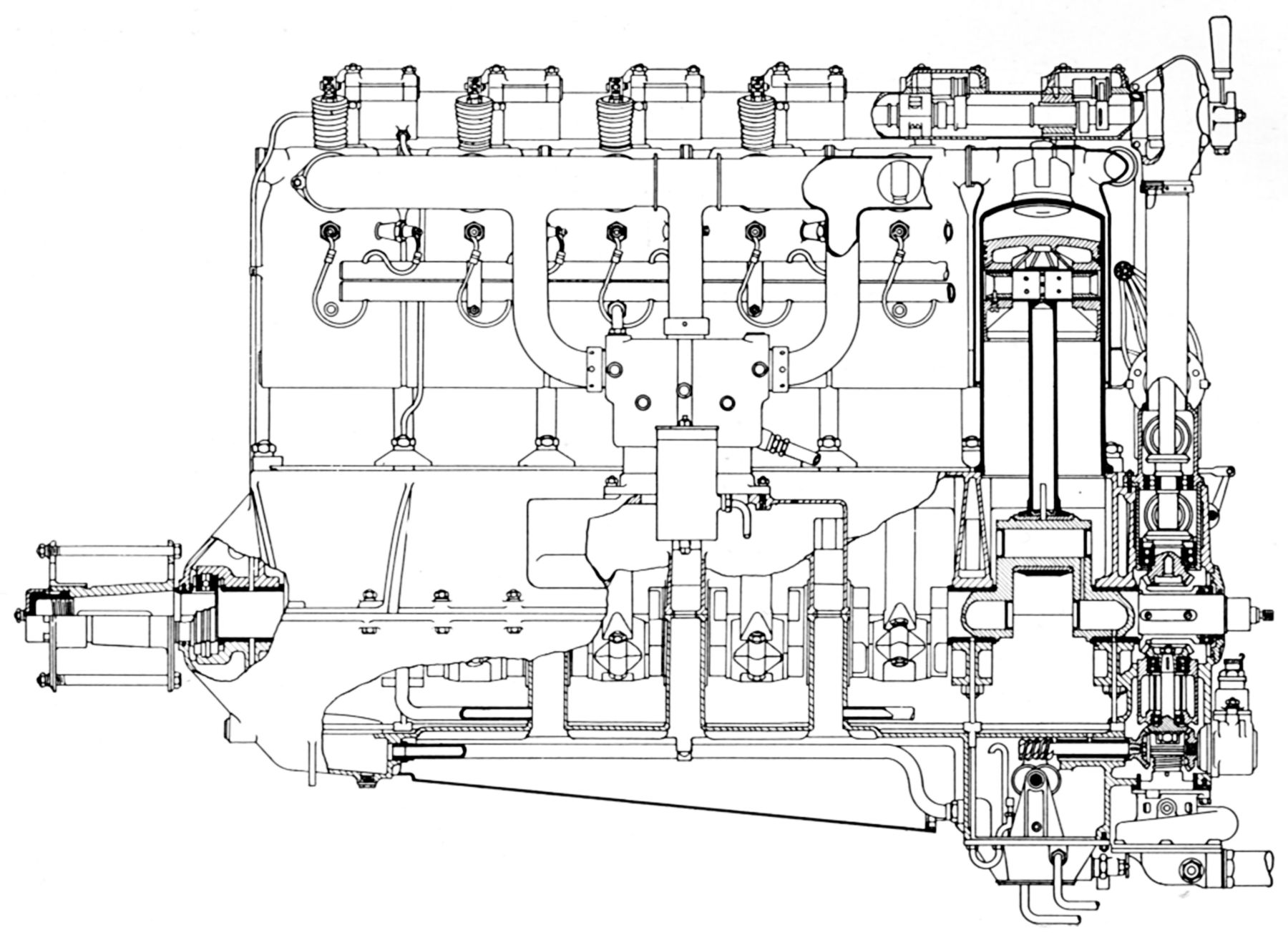
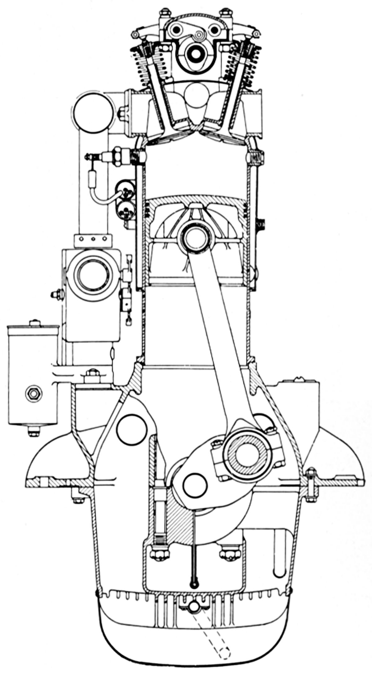
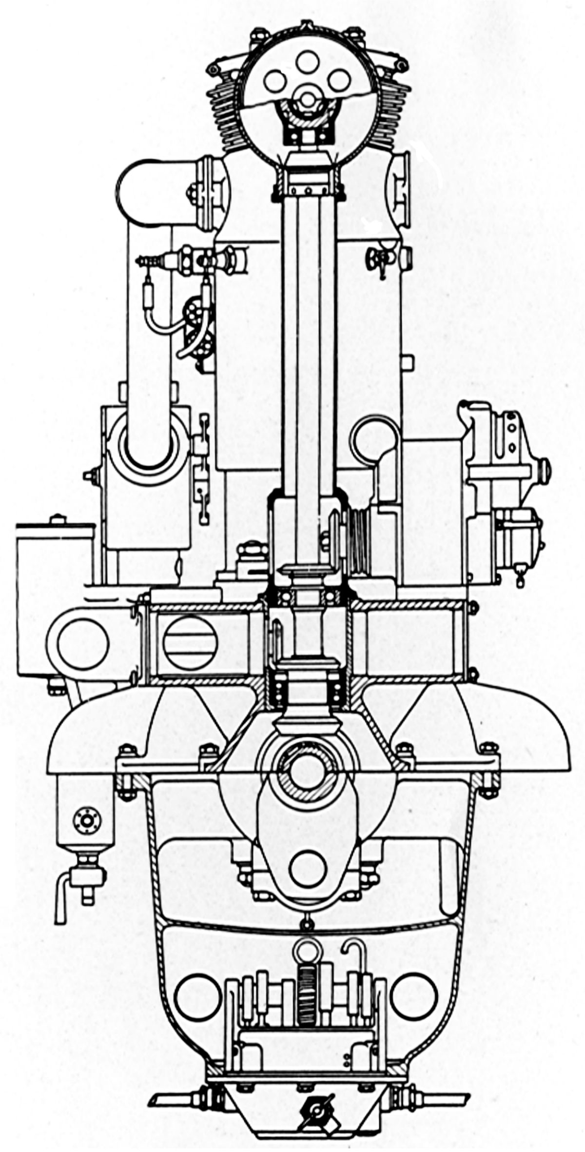
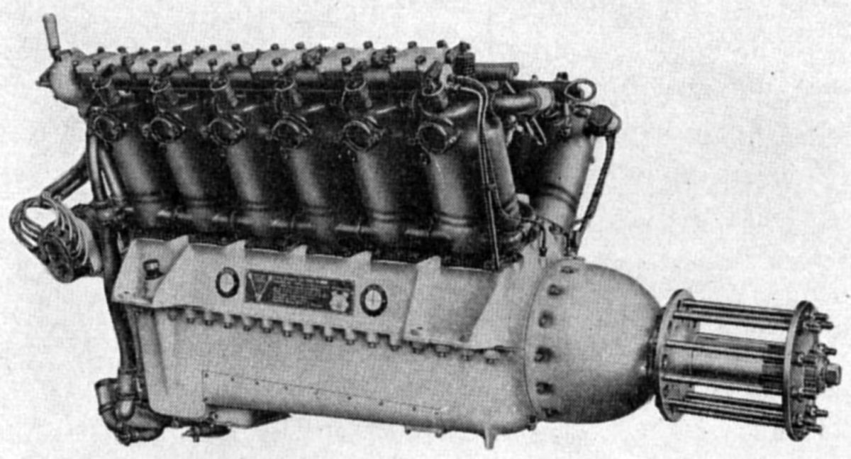
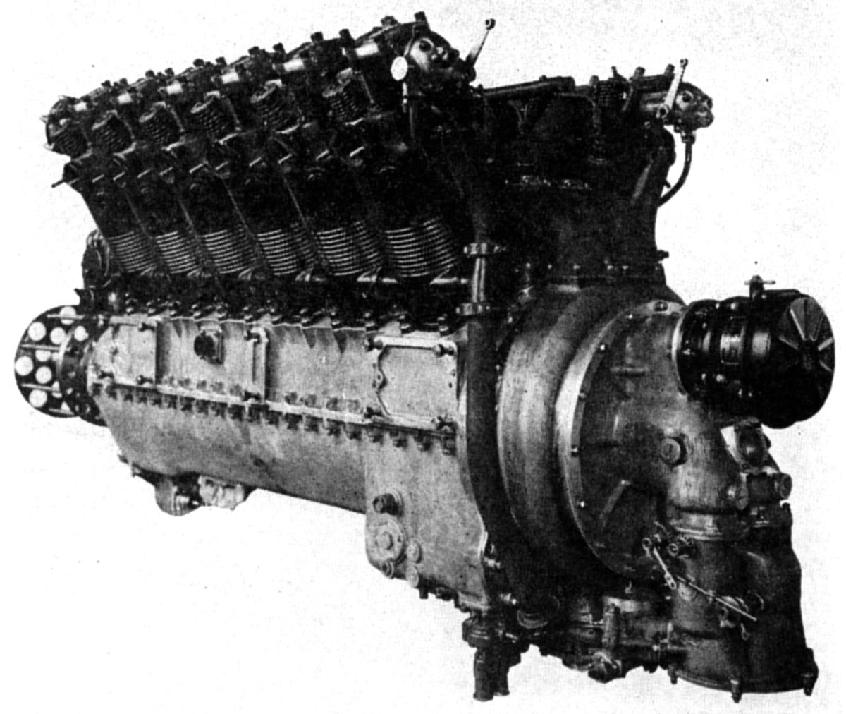
The 160 hp Beardmore, a larger six-cylinder vertical water-cooled engine, developed 180 hp at 1,400 rpm. Its bore was 142 mm (5.591"), stroke 175 mm (6.890"), displacement 16.629 l (1,014.8 in³), consumed 0.52 lb/hp/hr fuel and 0.03 lb/hp/hr oil. The 160 hp Beardmore's design and construction was similar to the smaller engines previously discussed. Its inlet valve opened 26° late, closed 36.75° late; its exhaust opened 45.25° early and closed 4° early. Dry weight was 600 lb and the water in the cylinder jackets weighed 4 lb 7 oz.
 |
 |
 |
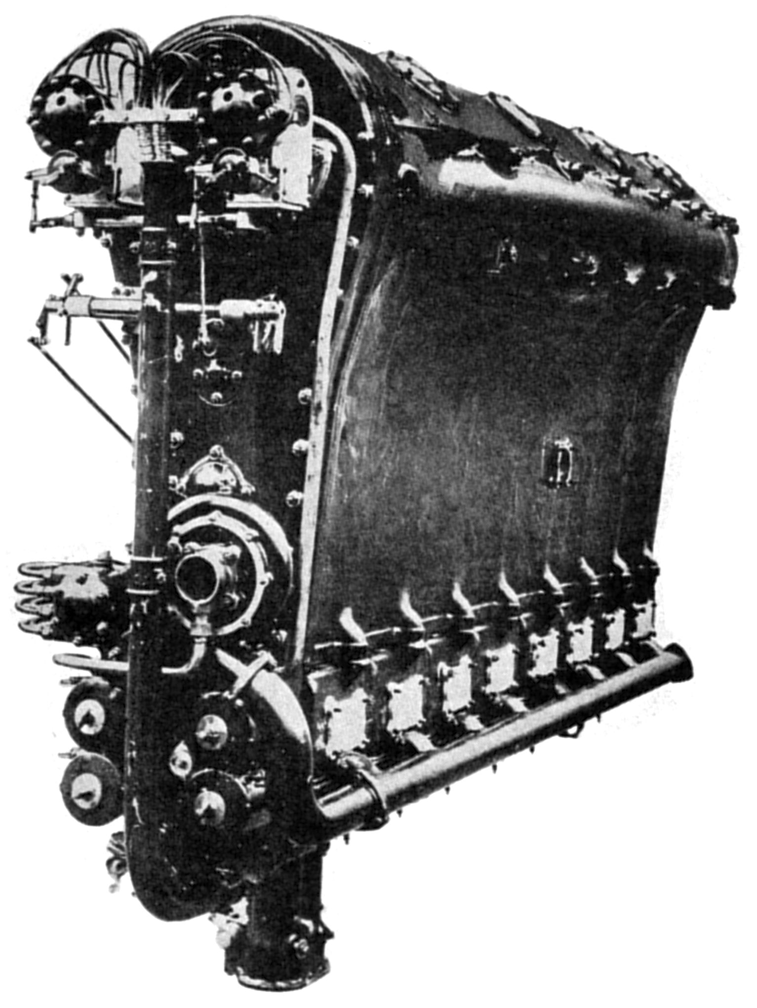
| Beardmore Cyclone Mark II (A39) | ||
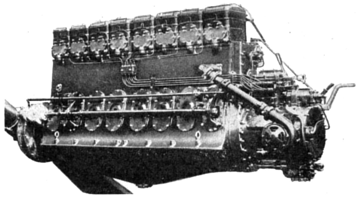
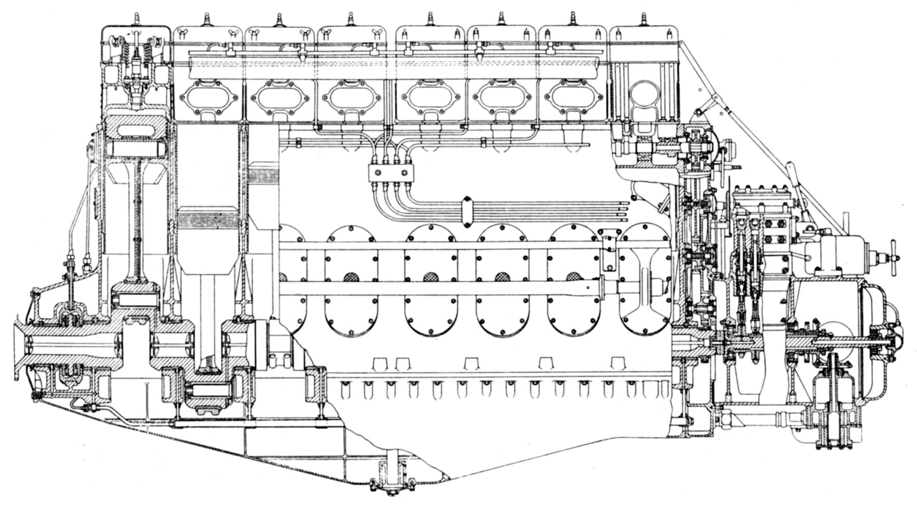
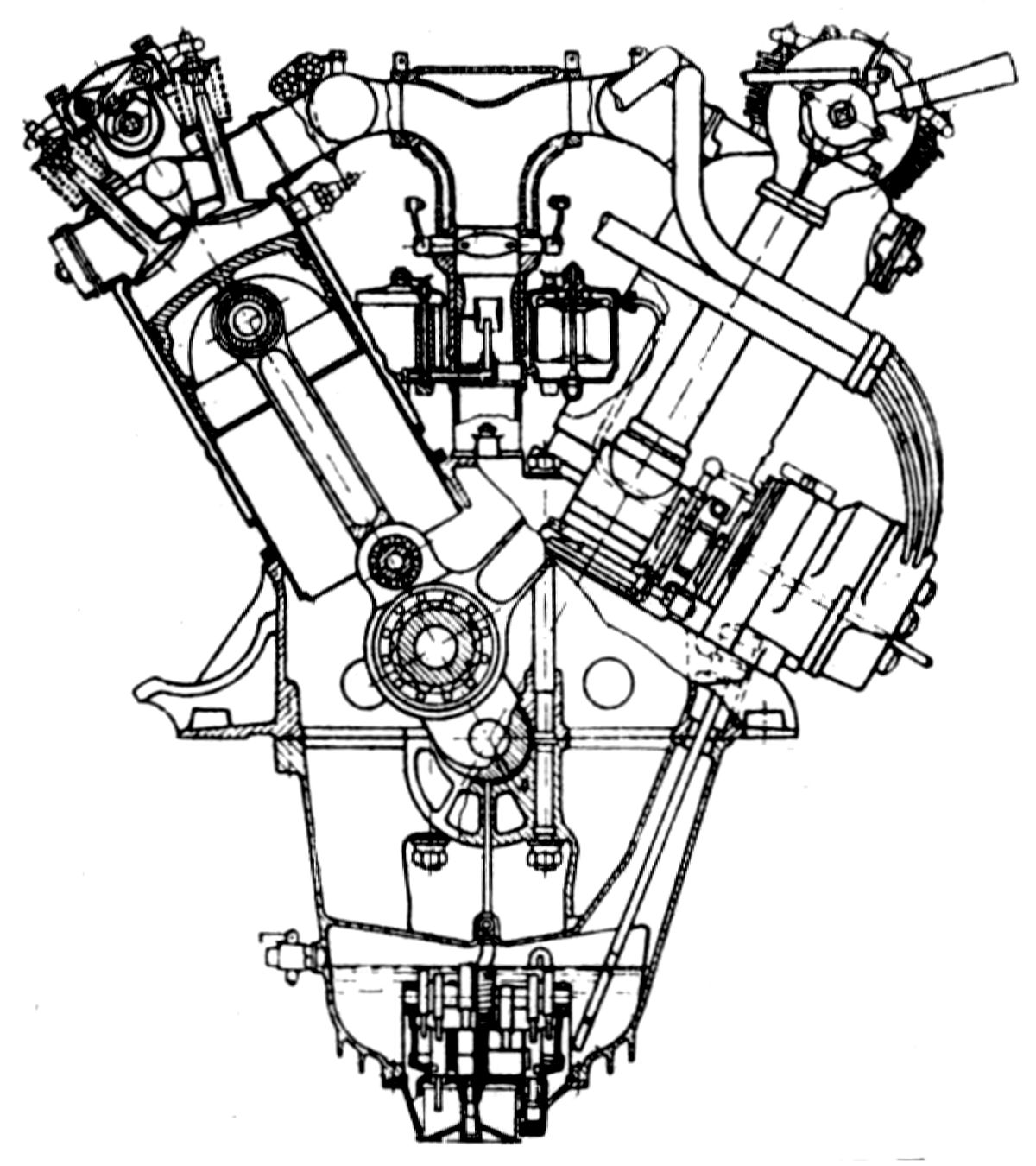
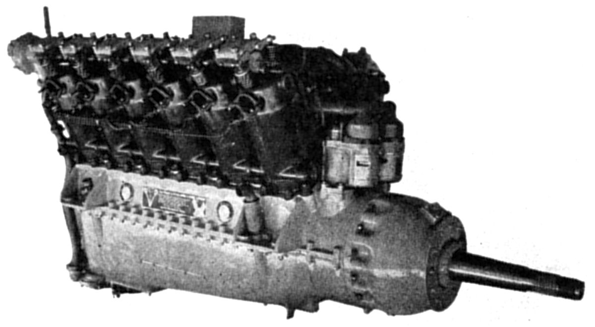
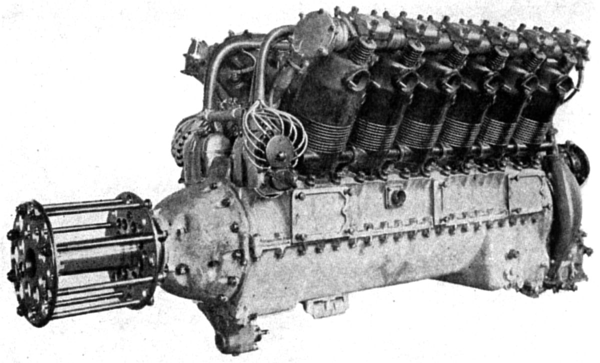
The Beardmore Cyclone Mark II engine, a later version of the original six-cylinder vertical water-cooled Cyclone, developed 850 hp at 1,350 rpm with a small carburetor and 950 hp with a large one. With a 8.625" (219.1 mm) bore and 12.000" (304.8 mm) stroke, the Cyclone Mark II displaced 4206.7 in³ (68.9 l) and weighed 2150 lb. Compression ratio was 5.25:1, specific fuel consumption 0.48 lb/hp/hr and specific oil consumption 0.01 lb/hp/hr. The Mark II was 80.3" (2,040 mm) long, 35" (889 mm) wide, and 60.37" (1,533 mm) high; height above the crankshaft center line was 42.25" (1,073 mm). Apparently the design objective was to obtain high output from few cylinders, thereby reducing the parts count while retaining maintenance accessibility. The engine was compact and very clean externally, and featured a small frontal area for the amount of power developed. The aluminum crankcase enclosed the crankshaft and main bearings carried on transverse girders, below which was a removable oil sump. The camshaft was carried in the upper crankcase. Inspection doors opposite each cylinder provided access on both crankcase sides. Thin steel cylinder liners inserted from the crankcase top were sealed at the bottom by a ring at the water space lower end. Each cylinder head with its valve gear formed a separate detachable with two inlet and two exhaust valves actuated by short pushrods and rocker arms. Two spark plugs were fitted in each cylinder head crown. The camshaft was driven by a gear train located in the crankcase rear. These gears also drove the various accessories mounted to the aft gear case, which could be readily detached. An accessory case mounted to the aft crankcase included two Watford magnetos, oil pressure and scavenge pumps, water and fuel pumps, gas distributor, and a gun synchronizer gear when the engine was used for military purposes. Duplex oil filters at the gearcase bottom connected both pressure and scavenging lines, which were provided with change-over valves so that either could he cleaned while the engine was running. Oil was delivered to the main hearings under pressure, and then passed through drilled crankpin passages. Tubular connections strapped to the tubular steel connecting rods shanks delivered oil to the hollow closed-end piston pins. Pistons were made from aluminum forgings, each fitted with three compression rings and one oil-scraper ring. A duplex Zenith carburetor worked in conjunction with a special induction system.
 |
 |
| Typhoon, Simoon (A39) | |
The Beardmore Typhoon was an inverted Cyclone version that weighed 2,233 lb and developed 925 hp at 1,350 rpm. Fuel consumption was 0.48 lb/hp/hr and oil consumption was 0.01 lb/hp/hr. Length was 80.3", width 38.5", and the height below crankshaft centerline was 48.525".
The Simoon was similar to the Typhoon, but it was inverted and had eight water-cooled cylinders. Bore was 8.5625" (217.5 mm), stroke was 12" (304.8 mm), displacement was 5,527.9 in³ (85.67 l), compression ratio was 5.25:1, and the dry weight 2,770 lb. It produced 1,100 hp at 1,250 rpm. Fuel consumption was 0.48 lb/hp/hr and oil consumption was 0.01 lb/hp/hr. The Simoon was 98" (2,489 mm) long, 37.6" (955 mm), wide, extended 62.325" (1,583 mm) below the crankshaft center line and 10.275" (261 mm) above it.
 |
 |
| Beardmore Tornado Mark III (A39) | |
The Tornado Mark III was a compression-ignition engine that resulted from several years of research at William Beardmore & Co. Five Tornados were installed and successfully tested during 1929 in the British airship R-101. This straight-eight had a 8.5625" (217.5 mm) bore, 12" (304.8 mm) stroke, 5,527.9 in³ (85.67 l) displacement and developed 585 hp at 900 rpm. Fuel consumption was 0.38 – 0.40 lb/hp/hr and oil consumption was 0.007 lb/hp/hr. It weighed 4,197 lb, or 7.17 lb/hp. Further development, reduced the weight to 4,000 lb. The fuel used had a specific gravity of 0.884 and a flash point (closed) of 166°F. Fuel was directly injected at high pressure by mechanical means to insure good atomization by the centrally-located injector. The latter was of plain outline, in the form of a shallow cylinder, with the atomizer located centrally in the cylinder head. The bmep was 100 psi and the compression ratio 12.25:1. The crankcase was a steel casting with thin steel cylinder liners. Inspection ports in each crankcase compartment were covered with light alloy doors that contained breathers. Pistons were machined from aluminum alloy forgings, and the cylinder heads were aluminum alloy castings with cast-in steel valve seats for the two inlet and two exhaust valves. The lower crankcase face formed the engine support and was closed by an aluminum-alloy oil sump. The crankshaft was carried upon ten white-metal-lined steel shells supported by aluminum main bearing caps. A double Michell bearing between the two end main bearings located the crankshaft and carried the propeller thrust. The main journal diameter was 5.75" (146 mm) while the crankpin diameter was 4.25" (107.9 mm). The H-section steel connecting rods were machined all over and featured a strapped-on pipe for piston pin lubrication. The rod big ends had directly-applied white-metal linings, while the small ends carried bronze bushings for the fully floating piston pins. The fuel injection pump was carried on a cylindrical bracket bolted to the engine aft end. This cylindrical bracket carried all the auxiliaries and their drives, such as the oil pressure and scavenging pumps, water pumps, and fuel supply and scavenging pumps, together with the fillers in both lubricating and fuel oil systems. The injection pump was bolted to the bracket top, and its plungers and valves were actuated by an eccentric shaft driven directly from the crankshaft end through air Oldham coupling. The forged steel pump block had cast iron liners for all plungers and reciprocating valves. Fuel pipes led directly to the injectors, which included vent valves to eliminate air trapped in the systerm. A decompresser operated on one inlet valve per cylinder, so that the engine could be motored over to prime the lubrication and fuel systems before actually starting. An auxiliary engine driving a Bendix pinion was utilized for starting. At first, an engine using gasoline for fuel was employed, but later a small compression-ignition engine was developed for starting. The Bendix pinion engaged with a toothed ring at the propeller end where the complete starting gear was enclosed in an aluminum casing. A spur gear train between the fuel pump bracket and crankcase drove the camshaft, which had four cams for each cylinder, each cam operating a roller tappet, push rod and rocker arm. The cylinders were cooled by water boiling and then being condensed with a centrifugal pump providing circulation.
Around 1931, Beardmore started to develop a twelve-cylinder horizontally-opposed high-speed compression-ignition engine for mounting within the leading edge of a thick monoplane wing. This engine developed 500 hp at 1,750 rpm and weighed less than 3 lb/hp. With a 6.0" (152.4 mm) bore, 6.5" (165.1 mm) stroke, and 1,102.7 in³ (18.1 l) displacement, the engine drove a propeller at 950 rpm through reduction gears. This engine never entered production.
Bentley
Walter Owen Bentley (W.O.) (16 Sep 1888 - 13 Aug 1971) was born in Hampstead, London to a wealthy family that arranged a private education at exclusive schools. As a schoolboy, W.O. was fascinated by trains. At the age of 16, he left college to enter a five-year apprenticeship as a Great Northern Railway engineer, where he began to earn his mechanical chops by studying the design, production and maintenance of railway rolling stock. He raced motorcycles, completed his GNR apprenticeship in 1910, studied theoretical engineering at Kings College in London, and in 1912 teamed with his brother, Horace Millner Bentley, to form the Bentley and Bentley organization, which sold French DFP (Doriot, Flandrin & Parant) automobiles. W.O. raced the DFP autos in hill climbs, but was unhappy with their performance. He modified the DFP engines by installing aluminum pistons and wilder camshafts, a combination that allowed him to set records at Brooklands in 1913 and 1914.
When Britain entered WWI, W.O. was commissioned in the Royal Naval Air Service. Knowing that aluminium alloy pistons, which ran cooler at higher compression ratios and produced more power, would aid the war effort, Bentley convinced the Admiralty to help share his practical experience and knowledge with aircraft engine manufacturers. He consulted with Rolls-Royce and Sunbeam, both of which began using aluminum pistons. The French Clerget rotary engine, widely used by the Royal Flying Corps and Royal Navy Air Service, was built under license in England by several concerns, including Gwynnes Ltd. However, this engine design was expensive and prone to overheating and seizure. The Admiralty ordered W.O. to Gwynnes where he developed aluminum alloy pistons and improved piston obturator rings for Clerget designs. W.O. wanted to also design new cylinders for the Gwynnes-built Clergets but Gwynnes was having none of that. The Admiralty assigned W.O. a design team for an aero engine of his own, which first ran in 1916.. It was initially known as the Admiralty Rotary No. 1 (A.R.1), later as the BR.1 The larger, more powerful BR.2 ran in 1918. W.O. was awarded the Member of the Order of the British Empire (MBE) for his contributions. After WWI, W.O. founded Bentley Motors Limited, which still manufactures automobiles to this day.
 |
| Bentley BR.1 (UKNA via David Birch) |
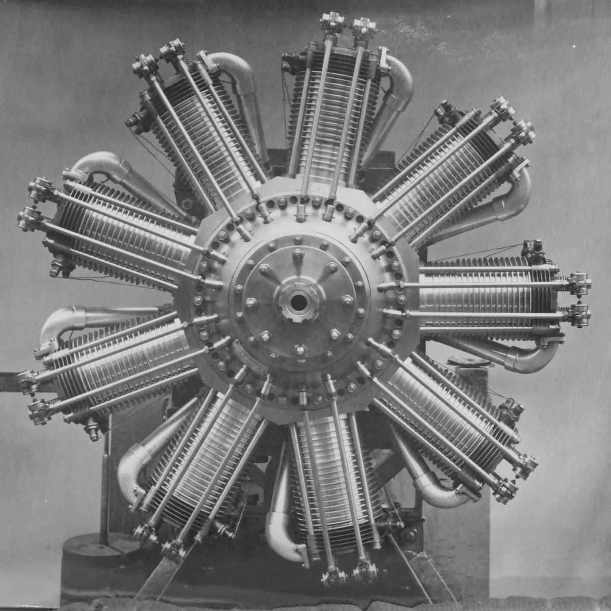
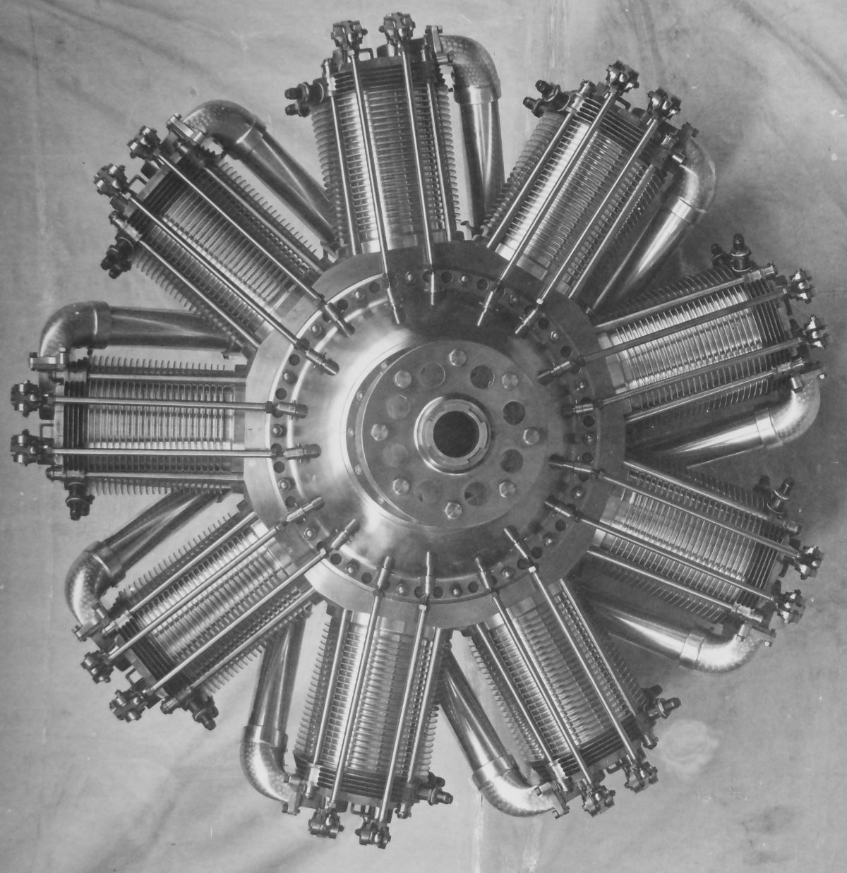
The BR.1 was a nine-cylinder air-cooled rotary that made maximal use of aluminum alloy and clever design; as a result it was significantly lighter than the Clerget. Rotary engines with steel cylinders suffered from uneven cylinder cooling, which distorted the bores, resulting in seizures, along with short piston and ring lifetimes. W.O. reasoned that aluminum alloy cylinders with thin, shrunk-in cast-iron liners would perform better, and they did. The BR.1 was first manufactured by the Humber Company of Coventry. With a 120 mm (4.724") bore, 170 mm (6.693") stroke, and 17.304 l (1,055.9 in³) displacement, the BR.1 was rated at 150 hp, but developed 154 hp at 1,250 rpm and 156 hp at 1,300 rpm. Its compression ratio was 5.9:1, fuel consumption was 0.59 lb/hp/hr, and oil consumption was 0.1 lb/hp/hr. Inlet valves opened 5° before outer dead center (ODC) and closed 58° after inner dead center (IDC); exhaust valves opened 72° before IDC and closed 7° after ODC. One block-tube carburetor was used, a plunger oil pump provided lubrication, and two A.D.S. magnetos furnished ignition. Dry weight was 405 lb, or 2.67 lb/hp.
BR.1 cylinders were cast from L.8 aluminum alloy (12% copper). These were heated and shrunk onto K.5 cast-iron liners. The S.11 or S.26 steel cylinder heads featured an inlet valve, an exhaust valve, and two spark plugs. L.8 aluminum alloy pistons with slightly concave heads had five thin K.5 cast iron piston rings; the obturator ring was eliminated. The piston pins were lubricated via a hollow-shank connecting rods. Each cylinder assembly was secured to the forged steel crankcase with four long studs and four castellated nuts that captured the cylinders and cylinder heads. A cam box with propeller hub was bolted to the crankcase fore side and a thrust box with induction passages was bolted to the crankcase aft side. The cam box and cam design was nearly identical to the Clerget design. Ball bearings were used throughout the engine and a double thrust bearing allowed the engine to run as a tractor or pusher.
 |
 |
 |
| (AEE) | (UKNA via David Birch) |
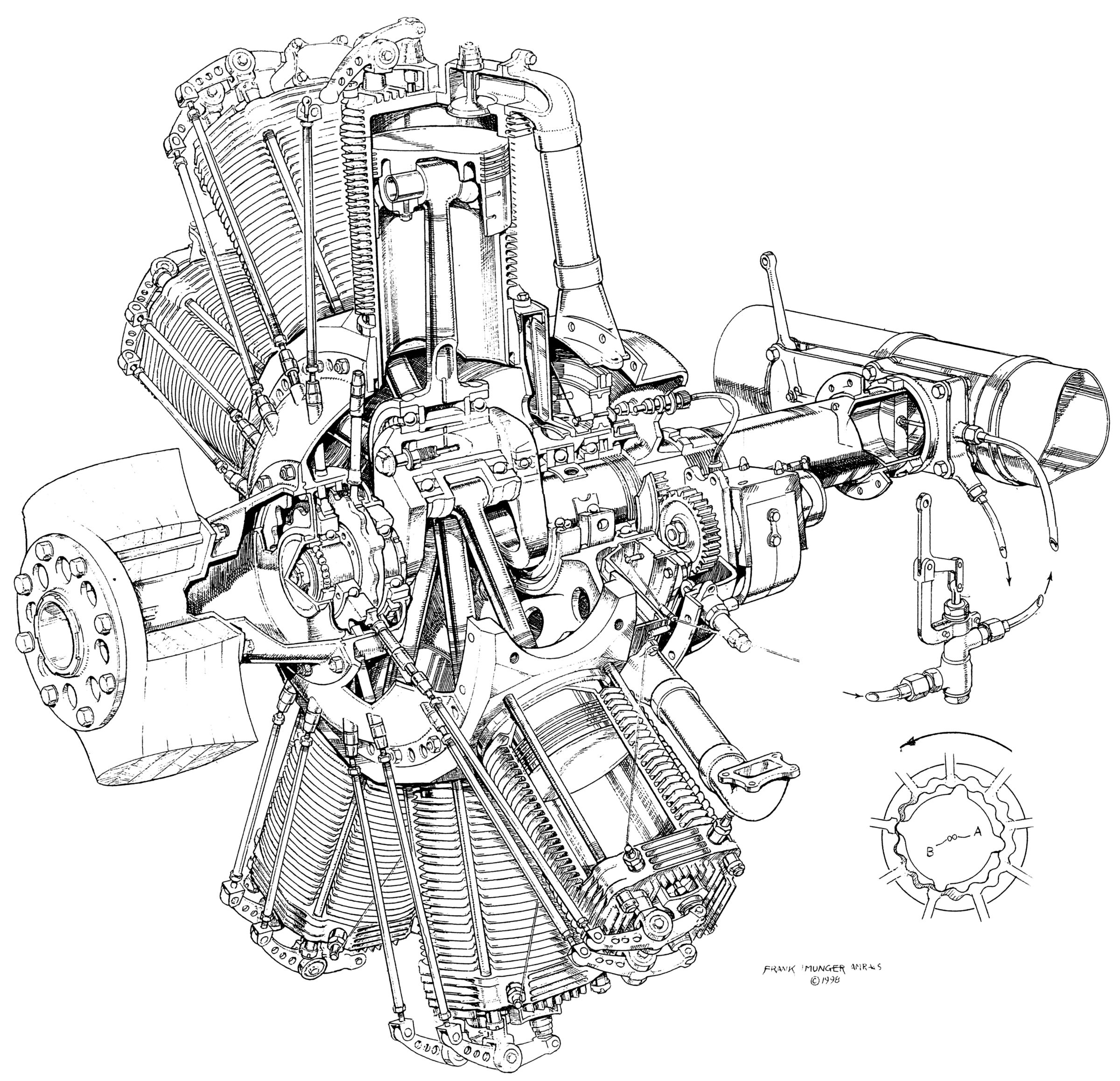
(Frank Munger) |
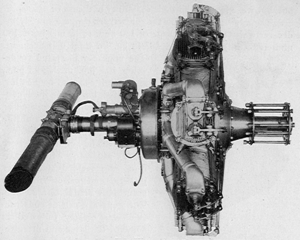
The BR.2, another nine-cylinder air-cooled rotary, had a 140 mm (5.512") bore, a 190 mm (7.480") stroke, and a 26.323 l (1,606.3 in³) displacement. The compression ratio was 5:1 to 5.2:1. Rated at 200 hp, the engine developed from 230 - 250 hp at 1,300 rpm with a 0.63 lb/hp/hr fuel consumption and 0.094 lb/hp/hr oil consumption. The blocktube mixing-valve carburetor had a 64 mm (2.52") throat and 4.25 mm (0.167") jet. BR.2 construction was, except for size, practically identical to the BR.1. BR.1 inlet valve clear diameter was 52 mm (2.047") and lift was 12 mm (0.472"). The exhaust valve clear diameter was 58 mm (2.284") and the lift was 13.5 mm (0.531"). Both valves had 30° seats. Inlet valves opened at ODC and closed 58° after IDC; exhaust valves opened 72° before IDC and closed 10° after ODC. The single-throw crankshaft was built up in three sections. Eight tubular-shank articulated connecting rods were attached to the master rod, which ran on ball bearings. Aluminum alloy pistons, ribbed inside, were fitted with five rings. Two M-L magnetos running at 2.25 times crankshaft speed supplied dual ignition. The BR.2 weighed 500 lb, or 2 lb/hp at maximum power. Overall diameter was 1,066.8 mm (42"), and the distance from the front support to the propeller hub front was 617.5 mm (24.313") The rear support was located 330.2 mm (13") behind the front support.
Approximately 30,000 BR.2 engines were built. Interestingly, the German Daimler company reversed-engineered and produced its own version of the BR.2 during WWI.
Bentley BR.1 Assembly Animation
 |
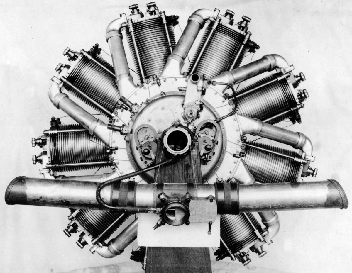 |
| Daimler-Built BR.2 (NARA) | |
Benz
 |
 |
| Kaiser Prize Engine (AEE) | |
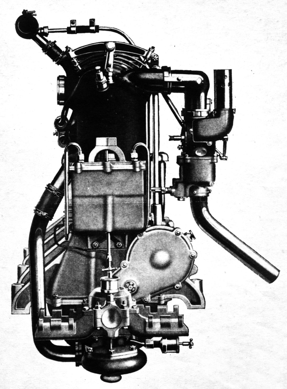
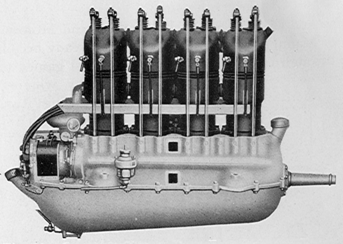
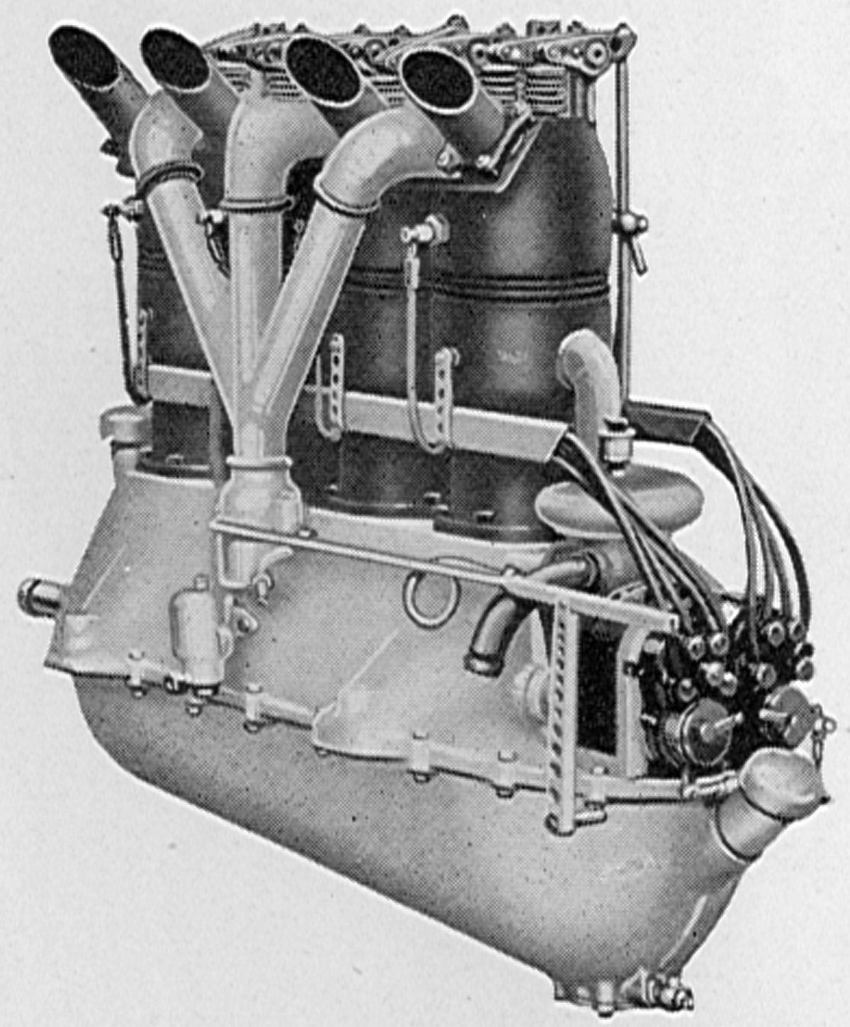
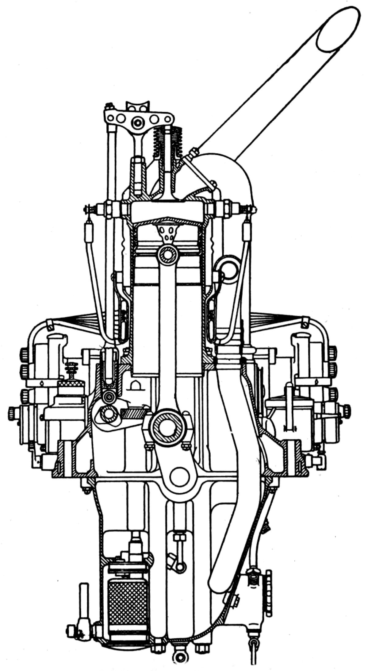
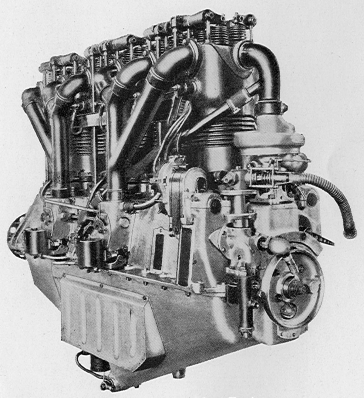
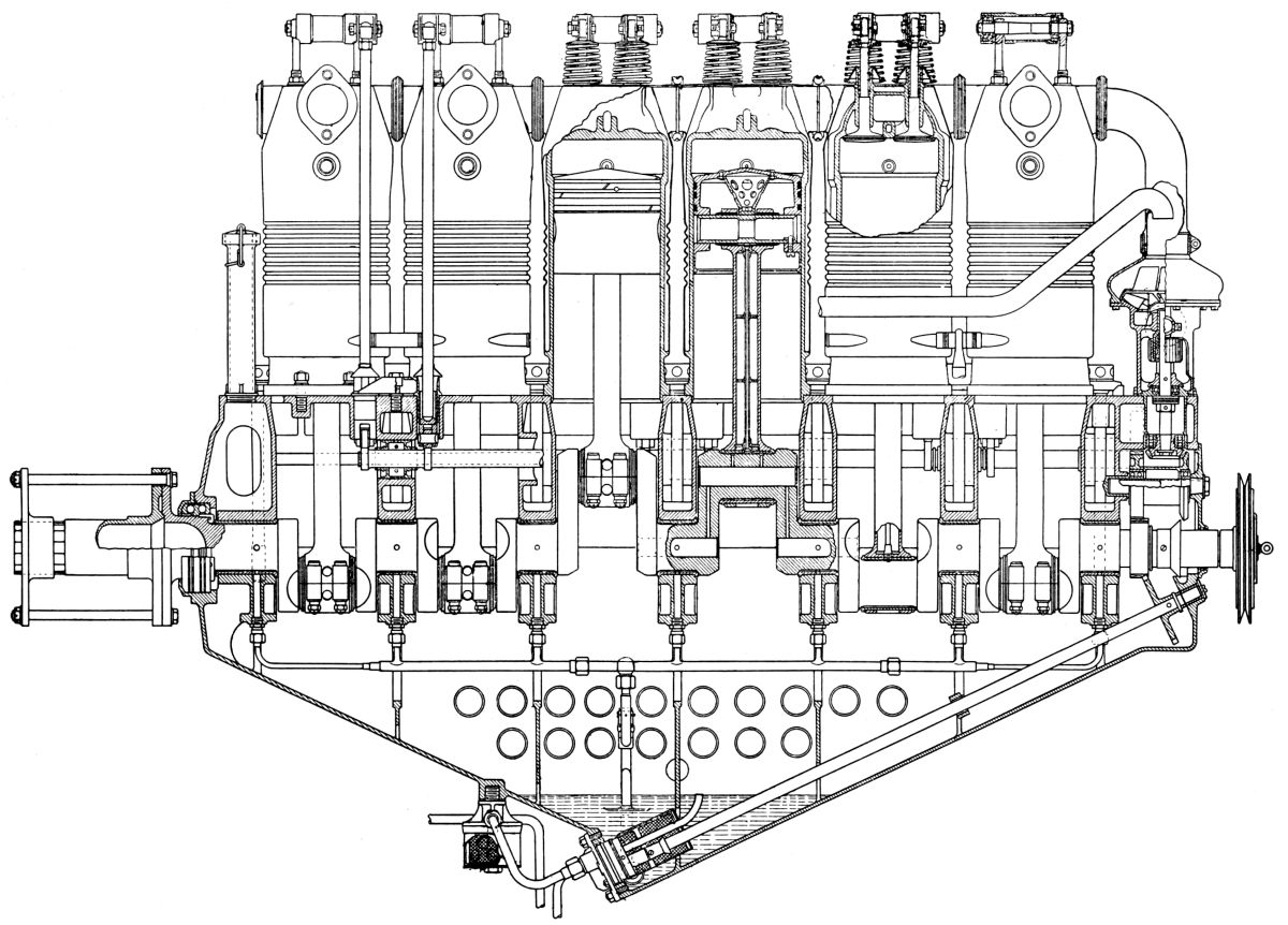
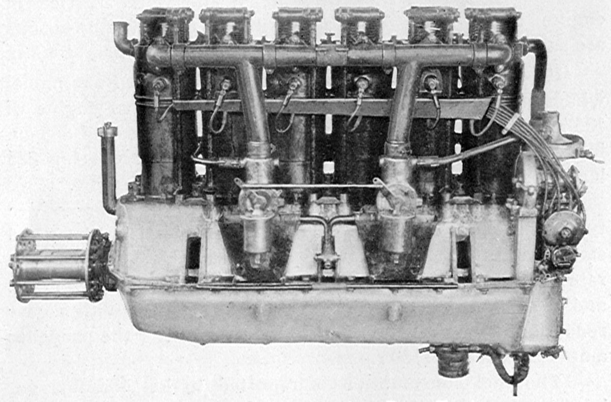
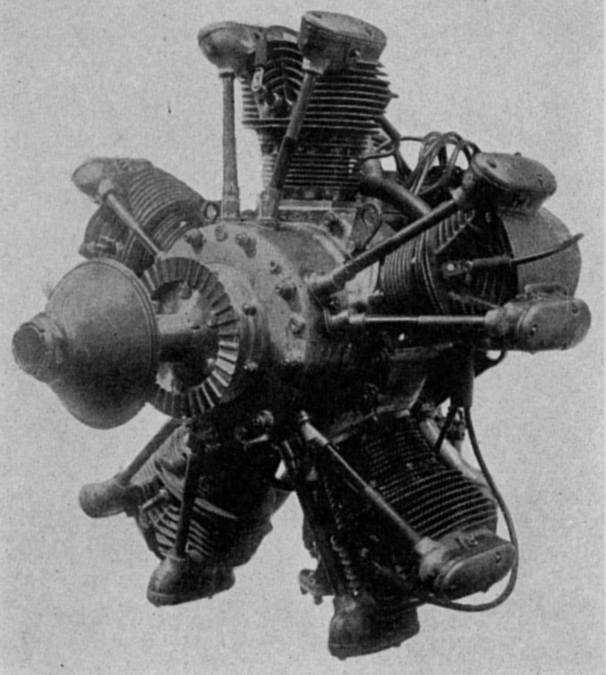
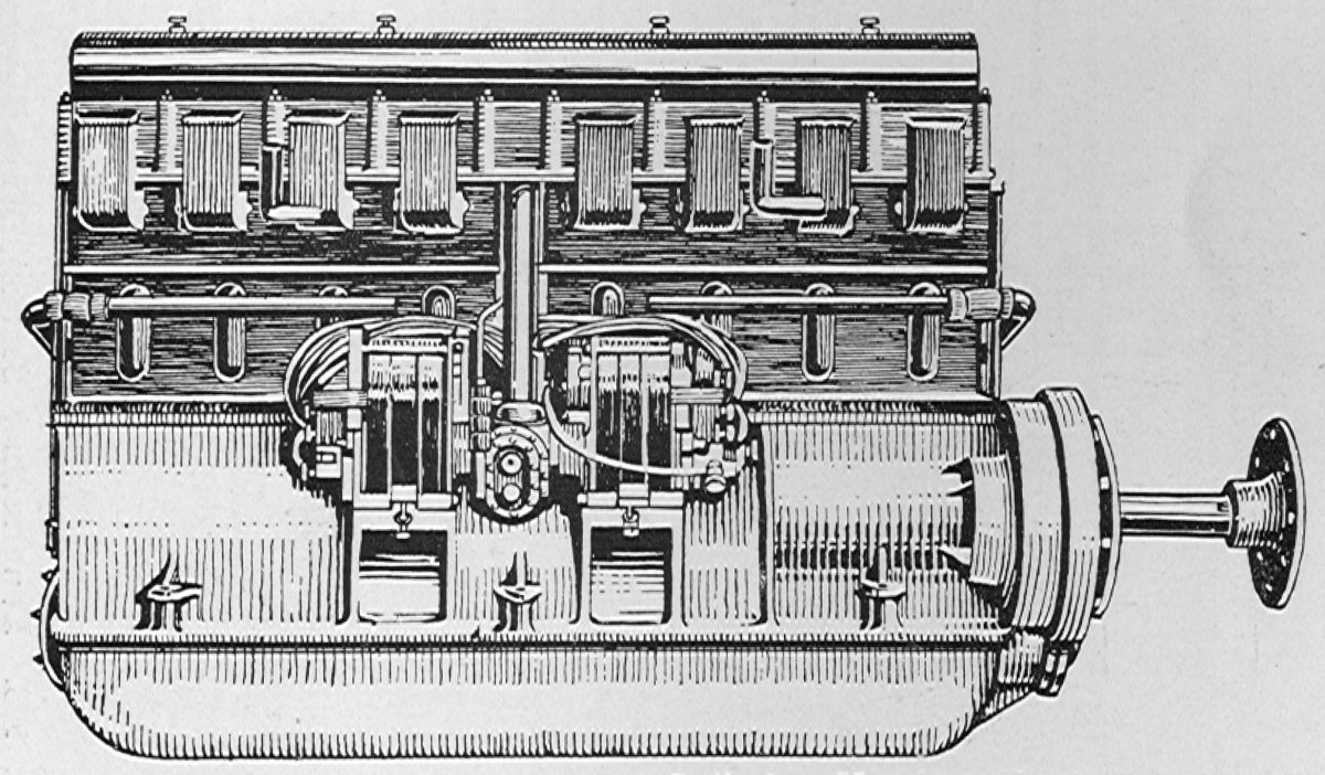
In 1912, Benz and Cie (Rheinishe Automobil and Moterenfabrik A.G. of Mannheim, Germany (hereinafter Benz), already famous for racing cars, constructed an engine specifically for the German Kaiserpreis (Kaiser Prize) aircraft engine competition and won first prize. It had four inline cylinders with a 130 mm (5.118") bore, 180 mm (7.087") stroke, and 9.557 l (583.2 in³) displacement. Rated output at 1,300 rpm was 100 hp Weight was 345 lb, or 3.45 lb/hp The separate cast-iron cylinders had welded sheet-steel water jackets and were offset from the crankshaft centerline by 20 mm (0.787"). Fuel consumption was 0.465 lb/hp/hr; oil consumption was 0.026 lb/hp/hr. A single Benz carburetor supplied mixture, a centrifugal water pump mounted to the engine rear circulated cooling water, and two Bosch magnetos furnished ignition. Eight of these engines were built in 1912 and 1913; one was used by Hellmuth Hirth in his long-distance flight from Berlin to Mannheim.
 |
 |
| Type BZ 1 (AEE) | |
The Type BZ 1 engine, developed in 1913 and built until 1915, was known originally as the Type F-B. It was a water-cooled six-cylinder in-line engine with a 106 mm (4.173") bore and 150 mm (5.906") stroke displacing 7.942 l (482.3 in³). It was rated 85 hp, but it developed 88 hp at 1,250 rpm and 95 hp at 1,250 rpm. Dry weight was 256 lb, fuel consumption was 0.528 lb/hp/hr and oil consumption was 0.026 lb/hp/hr. Two Benz carburetors furnished mixture with the air being drawn into the carburetors through crankcase ducts. Cooling water was circulated by a centrifugal pump. Pressure lubrication and dual magnetos were employed. The crankshaft ran in seven main bearings and the pistons were cast iron. Only eight BZ 1 engines were built.
The Type BZ 2 was a six-cylinder water-cooled in-line originally designated the Type F-D. It had a 116 mm (4.567") bore, 160 mm (6.299") stroke, and 10.146 l (619.1 in³) displacement. Rated at 110 hp, it developed 108 hp at 1,250 rpm, 110 hp at 1,300 rpm, and 115 hp at 1,350 rpm. Fuel consumption was 0.506 lb/hp/hr and the oil consumption was 0.022 lb/hp/hr. Dry weight was 440 lb. Cylinders of the usual Benz construction were mounted offset from the crankshaft center line by 20 mm (0.787"). A total of 417 were built.
RF.jpg) |
RA.jpg) |
| Type BZ 3 (AEE) | |
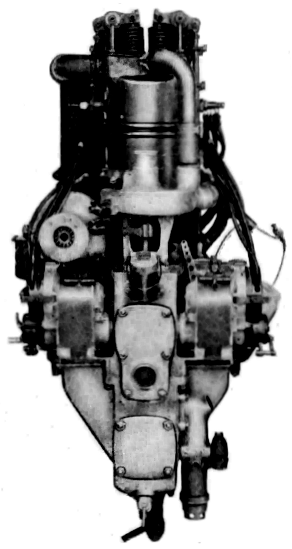
The Type BZ 3 was a water-cooled six-cylinder vertical engine, originally known as Type F-F. With a 130 mm (5.118") bore, 180 mm (7.087") stroke, 14.337 l (874.8 in³) displacement and 4.5:1 compression ratio, it was rated at 150 – 160 hp at 1,400 rpm. Fuel consumption was0.50 – 0.52 lb/hp/hr and oil consumption was 0.0264 lb/hp/hr. Some 3,000 were constructed, 50 of which were modified to turn counterclockwise for airship service. Two Benz carburetors provided mixture and two Bosch Z-H-6 magnetos furnished ignition. Oil pressure at 60 psi was maintained at the main bearings. Individual cast iron cylinders with welded-on jackets were offset from the crankshaft centerline by 20 mm (0.787"). Overhead valves were operated by pushrods and rocker arms. Inlet and exhaust valve clear diameter was 61.55 mm (2.423") and the lift was 11 mm (0.433"). The inlet valve opened at top center and closed 60° late; the exhaust opened 60° early and closed 16.5° late. The crankshaft ran on seven main bearings, the connecting rods had tubular shanks, and the cast-iron pistons were fitted with three rings. Dry weight was 539 lb.
 |
 |
|
| Type BZ 4 (AEE) | ||
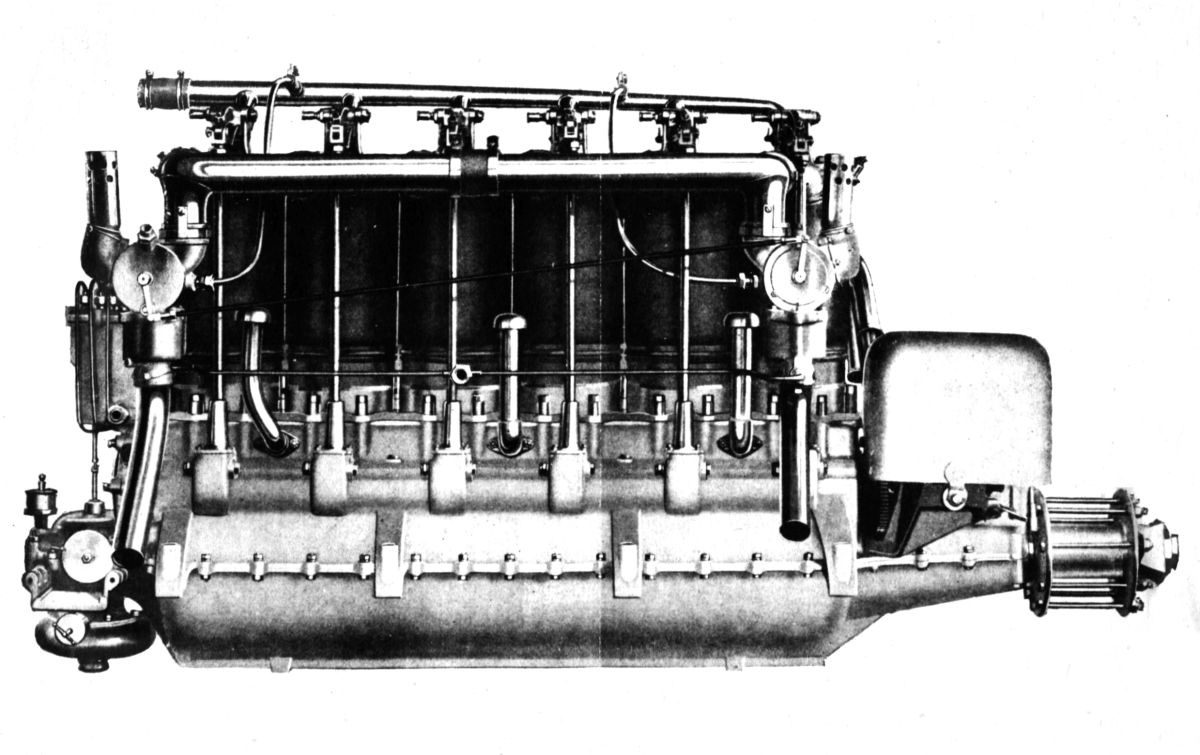
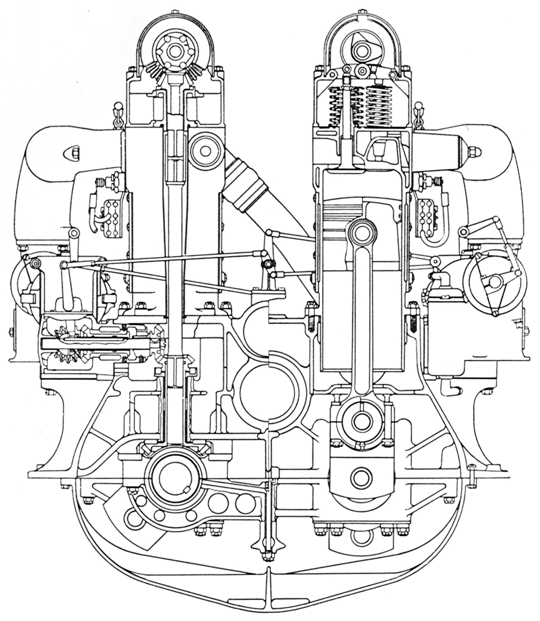
The Type BZ 4 was the most important Benz engine built during WWI with nearly 6,500 constructed between 1914 and 1918. Also referred to as the 200-hp model, this six-cylinder water-cooled in-line had a 145 mm (5.709") bore, a 190 mm (7.480") stroke, a 18.825 l (1,148.8 in³) displacement, and a 4.91:1 compression ratio. It developed 225 hp at 1,400 rpm (113 psi bmep) and a 275 hp at 1,500 rpm maximum. Fuel consumption was 0.59 lb/hp/hr and oil consumption was 0.023 lb/hp/hr. The mixture was furnished by two Benz carburetors mounted in the crankcase and each feeding three cylinders; air entered each carburetor intake via a passage through the crankcase. A normal oil pressure of 28 psi was maintained by a plunger pump working in conjunction with a sump-mounted plunger scavenge pump. The centrifugal water pump operated at 1.58 crankshaft speed, and dual ignition was furnished by two Z-H-6 Bosch magnetos. The individual cast-iron cylinders had sheet-steel water jackets welded in place. The overhead valves were operated by push rods on either side of the engine. The valve tappets were rollers mounted upon eccentrics that facilitated tappet clearance adjustment. There were four interchangeable valves, two inlet and two exhaust, per cylinder, with clear diameters of 52 mm (2.047"). Inlet valve lift was 11.8 mm (0.465"), and the exhaust valve lift 11.25 mm (0.443"). The inlet valve opened 10° early and closed 55° late; the exhaust valve opened 60° early and closed 20° late. The six-throw crankshaft was mounted in seven plain bearings. The tubular-shank connecting rods employed four-bolt caps. Pistons were cast from iron, and the piston head was supported by a conical steel forging bearing on the piston pin. Three wide rings were fitted at the piston top, Dry weight was approximately 816 lb, and the water within the cooling jackets weighed 30.9 lb. The Type BZ 4 was 59.0" long, 20.9" wide, and 51.7" high.
 |
| Type BZ DV (AEE) |
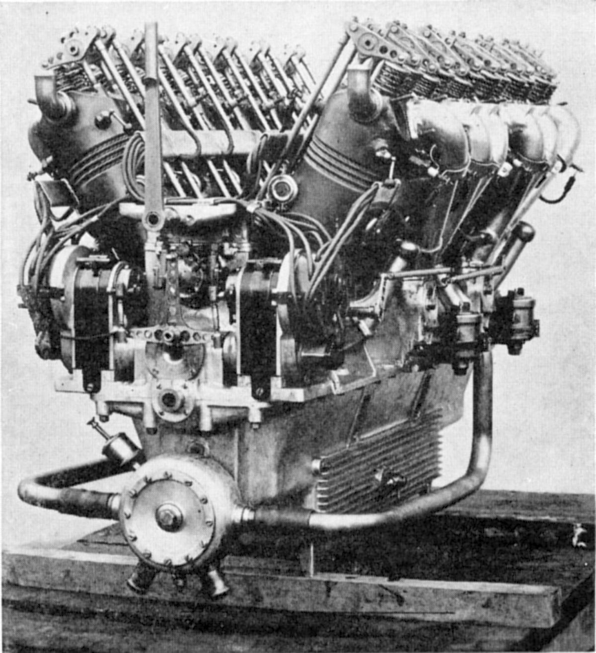
The Type BZ DV was Benz's first Vee-type engine. It had twelve cylinders at a 60° angle with 116 mm (4.567") bores, 160 mm (6.299") strokes, all displacing 20.291 l (1,283.2 in³). It was rated 220 hp at 1,400 rpm but was reported to have developed 250 hp. Mixture was supplied by four Benz carburetors, two for each cylinder row. A centrifugal water pump, and two Bosch magnetos driven by a transverse shaft, were situated at the rear of the engine. The oil was cooled by longitudinal cooling fins in the aluminum crankcase, supplemented by crankcase air ducts feeding the carburetors.
 |
 |
| Type BZ 3a (AEE) | |
The Type BZ 3a was an improved and enlarged BZ 3 whose design followed the BZ 4. Germany built nearly 350 between 1915 and 1918. It had six water-cooled cylinders with 140 mm (5.512") bores, 190 mm (7.480") strokes, and a 17.549 l (1,070.9 in³) displacement. While rated at 185 hp, the normal output was 195 hp at 1,400 rpm. Normal bmep was 117 psi and bmep at maximum power was 110 bmep. With a 5.1:1 compression ratio the engine was most efficient at 2,500 meters. Fuel consumption ranged from 0.474 to 0.491 lb/hp/hr. The mixture was furnished by two Benz BZ-3-A-137 carburetors having 42 mm (1.653") throats and 1 mm (0.039") main jets. A gear oil pump delivered approximately 23 psi to the bearings in the dry-sump lubrication scheme. A 4.5" diameter six-vane centrifugal pump delivered water to the cylinder jackets. Bosch Z-H-6 magnetos supplied dual ignition. The individual cylinders had steel barrels that were screwed into cast-iron heads and surrounded by sheet steel water jackets welded in place. The overhead valves were operated through push rods and rocker arms having eccentric mountings for the rollers, which acted as tappets. There were two inlet and two exhaust valves per cylinder, each with a 43 mm (1.693") clear diameter, 11 mm (0.433") lift, and 30° seats. The inlet valve opened 5° late and closed 45° late; the exhaust opened 55° early and closed 18° late. The six-throw crankshaft was mounted in seven plain bearings. The tubular-shank connecting rods employed four-bolt caps. The aluminum pistons were ribbed inside and fitted with four rings. Dry weight was 605 lb, and the water in the cooling jackets weighed 19 lb. The engine was 51.5" long, 21.5" wide, and 40" high.
 |
 |
 |
| Type BZ 3bV (A39) | ||
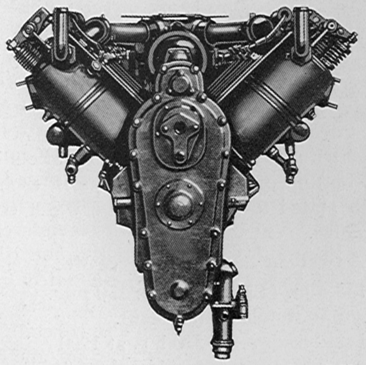
The Type BZ 3bV was developed in 1917, and about 180 engines were built before WWI's end. It was a water-cooled 90° V-8 with a 135 mm (5.315") bore and stroke and a 15.459 l (943.4 in³) displacement. The engine was rated at 195 hp, but developed 200 hp at 1,800 rpm and 215 hp at 2,000 rpm. Propeller reduction gears with a 29:19 ratio produced a 1,180 rpm nominal propeller speed. The maximum output was at 1,800 meters. Fuel consumption was 0.485 lb/hp/hr and oil consumption was 0.033 lb/hp/hr. Compression ratio was 5.7:1, dry weight was 683 lb, and water jacket water weight was 22 lb. Benz initially positioned the carburetor below the engine, but later engines used a single Benz two-jet carburetor within the Vee. A vertical shaft at the rear drove the centrifugal water pump as well as the oil pumps, but these accessories were originally located in front. Two Bosch magnetos were driven from a transverse shaft at the engine front end. Two exhaust valves and one inlet valve operated by means of push rods and rocker arms from a camshaft located in the Vee. In another version, the magnetos were placed transversely at the rear of the engine, and a carburetor on each side fed into pipes leading to manifolds in the Vee.
 |
 |
| Type BZ 5b (A39) | |
The Type BZ 5b was similar to the Type BZ 3bV; about 25 were built during 1918. These water-cooled 60° V-12s had a 135 mm (5.315") bore, 150 mm (5.906") stroke, and a 27.765 l (1,572.3 in³) displacement. Its rated output was 300 hp at 1,800 rpm and 400 hp at 2,000 rpm. An epicyclic reduction gear with a 29:19 ratio was fitted. Fuel consumption was 0.496 lb/hp/hr and oil consumption was 0.026 lb/hp/hr. Mixture was furnished by two duplex carburetors, each throat feeding three cylinders. Bosch twelve-cylinder magnetos provided dual ignition. Dry-sump lubrication provided a 7.5 psi minimum pressure to the bearings. Individual cylinders had steel barrels screwed into cast-iron heads and encased by sheet-steel water jackets welded in place. The camshaft was located centrally in the Vee and operated one inlet and two exhaust valves in each cylinder via push rods and rockers. The six-throw seven-main-bearing crankshaft used articulated tubular-shank connecting rods. Aluminum pistons with eight ribs under the head and were fitted with four top compression rings and one lower oil-scraper ring. Cooling water was circulated by a centrifugal pump with double outlets branching to each bank's end cylinder top and bottom. Dry weight was 948 lb and the water-jacket water weight was 35.3 lb.
 |
| BZ 5 (A39) |
The Type BZ-5 was another water- cooled 60° V-12 with a 145 mm (5.709") bore, 170 mm (6.693") stroke, and 33.687 l (2,055.7 in³ displacement. It was rated at 300 hp, but developed 320 hp at 1,500 rpm. The propeller was geared 29:17. Fuel consumption was 0.496 lb/hp/hr and oil consumption 0.026 lb/hp/hr. Dry weight was 1,056 lb and the cooling jacket water weighed 39.7 lb.
 |
 |
 |
| Type BZ 6V (A39) | ||
The Type BZ 6V was a water-cooled 60° V-12 of which about 25 units were constructed from 1916 to 1918; four were installed in one large airplane. It had a 155 mm (6.102") bore, 200 mm (7.874") stroke, 45.286 l (2,763.5 in³) displacement, was rated 500 hp, but delivered 575 hp at 1,500 rpm and 675 hp at 1,600 rpm. Maximum output was at 1,800 meters, dry weight was 1,531 lb, and the cooling jacket water weight was 77 lb. A propeller reduction gear was not built into the engine, but a crankshaft flange was provided for connecting to a standard gear set by means of springs. The mixture was supplied by four Benz carburetors sunk into the crankcase as in some of the earlier Benz engines. Each welded steel cylinder had two inlet and two exhaust valves operated by individual push rods and rocker arms from three camshafts, two located at the crankcase outside and one in the Vee. Fuel consumption was 0.496 lb/hp/hr and oil consumption was 0.033 lb/hp/hr. Four plunger pumps located at the engine rear delivered pressurized lubrication. Master connecting rods had an H-section shank and the link rods had tubular shanks. A centrifugal water pump was driven from the upper end of a vertical shaft that also drove four six-cylinder magnetos placed transversely at the engine rear, one pair above the other.
During WWI, Benz experimented with engines of high power output. One water-cooled six-cylinder vertical engine developed 623 hp at 1,400 rpm. Its bore was 225 mm (8.858"), stroke was 300 mm (11.811"), and displacement was 71.569 l (4,367.4 in³). Each cylinder had six valves and four spark plugs. During tests, the crankcase broke from severe vibration, and the cast-iron pistons, although sprayed by oil jets from underneath, overheated. Benz also experimented with seven-cylinder radials in 1914 and 1918, but development never left the test bench. Following the Armistice, construction of aircraft engines was discontinued by Benz and Cie, and was not resumed until after the amalgamation with the Daimler-Motoren-Gesellschaft in 1926, the new firm becoming known as Daimler-Benz-Aktienlesellsrhaft.
BMW
BMW engines were originally built by the Bayerische Motoren Werke of Munich, Germany. An early engine, the BMW IIIa, replaced the Mercedes 180 hp engine in German aircraft during the latter part of WWI. BMW construction was typical of most German designs, but the engine exhibited unusually low fuel consumption and altitude performance, which resulted from a high compression ratio and choked down carburetor setting.
 |
 |
 |
 |
 |
 |
 |
 |
 |
|
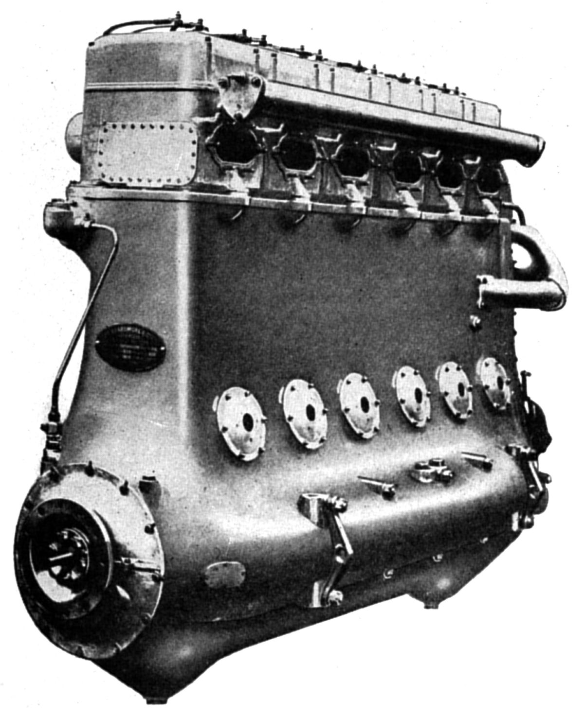
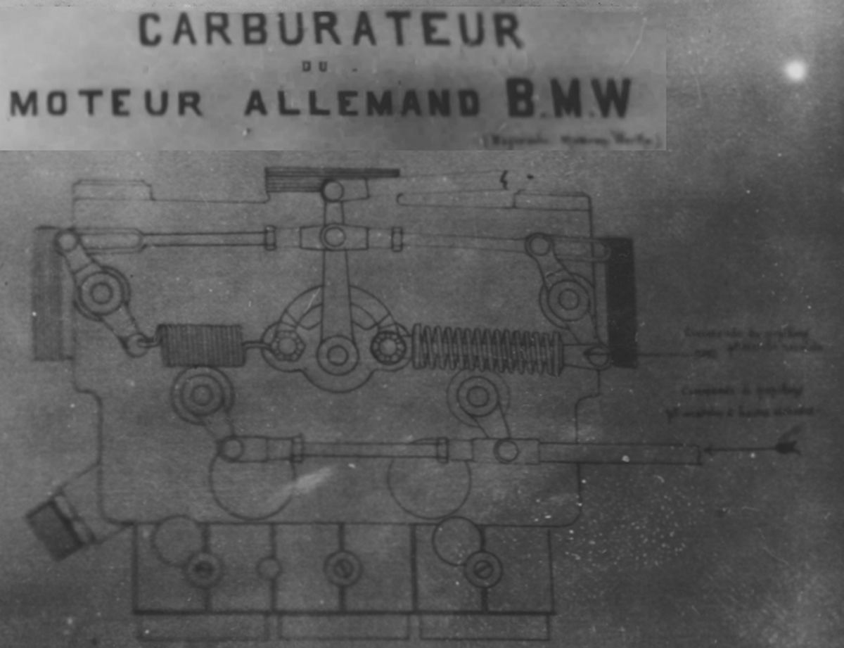
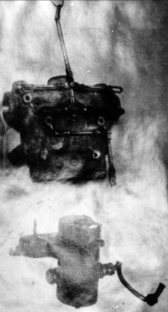
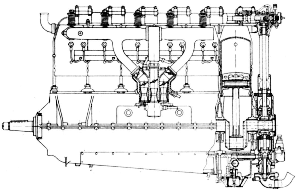
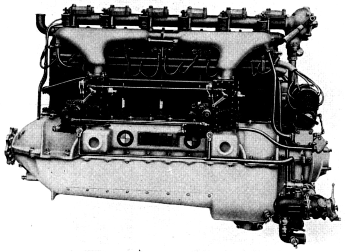
| BMW 111a (NARA, AEE, A39) | BMW 111a Carburetor (NARA) | ||||||||
The BMW 111a was a water-cooled vertical six-cylinder with a 150 mm (5.906") bore, 180 mm (7.087") stroke, 19.085 l (1,164.6 in³) displacement and 6.42:1 compression ratio that was rated 180 hp at 1,410 rpm and 254 hp at 1,600 rpm. Maximum bmep, which occurred at 1,300 rpm, was 115 psi. Fuel consumption was 0.42 lb/hp/hr and oil consumption 0.042 lb/hp/hr. A specially-designed triplex carburetor with a 27-mm (1.063") center venturi and 26-mm (1.024") side venturis was used. Oil at 24 psi was delivered to the main bearings by a Mercedes-type plunger pump. A two-outlet centrifugal water pump delivered cooling water to the front cylinder top and aft cylinder bottom. All cylinder water passages were connected together. Dual ignition was supplied by two Bosch 2-H-6 magnetos. Dry weight was 643.5 lb, or 2.75 lb/hp. Cylinders were machined from steel forgings, that had sheet metal water jackets welded in place. The overhead camshaft operated one inlet and one exhaust valve in each cylinder. The valves had a 68 mm (2.677") clear diameter and 30° seats. Inlet valve lift was 12.9 mm (0.508") and exhaust valve lift was 12.48 mm (0.491"). Inlet valves opened 5° early and closed 36° late; exhaust valves opened 60° early and closed 20° late. The six-throw crankshaft ran in seven plain bearings with white metal lining a steel shell. Tubular shank connecting rods attached inside-ribbed aluminum pistons with three rings each.
Shortly after the WWI, the original company ceased operations and its rights were acquired by the Bayerische Flugzeug Werke, which changed its name to Bayerische Motoren Werke and started manufacturing aircraft, automobile, and motorcycle engines in the original Munich factory. A 4-hp BMW motorcycle engine was used in light planes around 1924.
 |
| BMW IV (A39) |
The BMW IV, which replaced the BMW 111A, used the same engine bearers and was interchangeable with the earlier model. It had a larger displacement and incorporated several minor detail design changes, including a compression ratio was increase that allowed it to develop its full normal horsepower up to 11,500 ft. With a 160 mm (6.299") bore, 190 mm (7.480") stroke, 22.921 l (1,398.7 in³) displacement and 6:1 compression ratio, it produced 250 hp at 1,460 rpm. Fuel consumption was 0.45 0 0.49 lb/hp/hr and weight was 681 lb.
 |
| BMW IV (A39) |
The BMW Va, introduced in 1927, was intended to replace the BMW IV. It had the same bore, stroke and displacement. The six water-cooled vertical cylinders were of built-up welded steel construction. A tabular casing on the cylinder heads contained the camshaft, which operated single inlet and exhaust valves through rocker arms projecting outside. All accessories were located at the engine rear, with the magnetos crosswise and driven from the same vertical shaft that drove the overhead camshaft. Fuel, oil and water pump drives were also provided. Each of the two Zenith carburetors supplied three cylinders and a balance tube connected the two manifolds. The engine was 70.67" long, 25" wide, 44.61" high and weighed 697 lb. The BMW Va was available with three compression ratios (CR). With a 7.3:1 CR it produced 385 hp at 1,650 rpm and 320 hp at 1,555 rpm with a 0.473 lb/hp/hr fuel consumption. With a 6:1 CR output was 370 hp at 1,650 rpm and 320 hp at 1,565 rpm with a 0.484 lb/hp/hr fuel consumption. With a 5.5:1 CR maximum output was 350 hp at 1,650 rpm and normal output was 320 hp at 1,600 rpm with a 0.495 lb/hp/hr fuel consumption. The engine could be fitted with a compressed-air starter, hand turning gear, or an inertia starter with either hand or electric drive.
The BMW V was a water-cooled vertical six-cylinder with a 165 mm (6.496") bore and 190 mm (7.480") stroke that displaced 24.376 l (1,487.5 in³). The design closely followed the BMW Va type except for the cylinder construction. Steel cylinder barrels were inserted into an aluminum castings and rubber rings sealed the water jacket lower ends. The combined cylinder head and camshaft housing was an aluminum casting held to the cylinders by four screwed-in valve seats per cylinder. The camshaft was fully enclosed and driven from a vertical shaft at the engine rear. Dry weight was 737 lb. The BMW V was available with three compression ratios. With a 7.3:1 CR, maximum output was 410 hp at 1,650 rpm and normal output was 320 hp at 1,520 rpm with a 0.484 lb/hp/hr fuel consumption. When the CR was 6:1, maximum output was 400 hp at 1,650 rpm and normal output was 320 hp at 1,535 rpm, and a 0.495 lb/hp/hr fuel consumption. With a 5.5:1 CR, maximum output was 370 hp at 1,650 rpm and normal output was 320 hp at 1,570 rpm with a 0.504 lb/hp/hr fuel consumption.
 |
 |
| BMW VI (A39) | |
The BMW VI was a 60° V-12 using BMW IV cylinders and design features. With a 160 mm (6.299") bore, 190 mm (7.480") stroke and 45.842 l (2,797.5 in³) displacement, it weighed 1,222 lb with an aluminum alloy crankcase and 1,034 with an Elektron (magnesium alloyed with zirconium, thorium and zinc) crankcase. The crankshaft was carried in seven plain bearings. The connecting rod big ends ran on roller bearings, the magnetos were driven from the camshaft drive shafts and inclined at a 30° angle to the engine horizontal centerline. A bevel-geared hand starter was attached to the crankcase rear end. It was 71.3" long, 33.8" wide, and 43.1"high and featured a tapered propeller shaft. BMW carburetors were provided when maximum economy was desired while Zenith carburetors provided maximum power. Three compression ratios were available. With a 7.3:1 CR maximum output was 750 hp at 1,650 rpm and normal output was 500 hp at 1,443 rpm with a 0.473 lb/hp/hr fuel consumption. With a 6:1 CR, maximum output was 660 hp at 1,600 rpm and normal output was 500 hp at 1,460 rpm with a 0.484 lb/hp/hr fuel consumption. With a 5.5:1 CR, maximum output was 660 hp at 1,600 rpm and normal output was 500 hp at 1,467 rpm with a 0.495 lb/hp/hr fuel consumption. The intake opened 5° early and closed 55° late; the exhaust opened 40° early and closed 24° late. The BMW VI was available in direct-drive and 1.6:1 Farman-geared configurations. The geared engine with an aluminum crankcase weighed 1,199 lb and 1,111 lb with the Elektron crankcase. The geared engine was known as the BMW VI U. Direct-drive and geared performance were identical, but the geared engine's overall length was 70.5" (including inertia starter) the propeller has a serrated mounting flange.
 |
| BMW VIIa (A39) |
The BMW VIIa was a 60° V-12, essentially a doubled BMW Va with the same 160 mm (6.299") bore and 190 mm (7.480") stroke but displacing 45.842 l (2,797.5 in³). Bosch magnetos were at the engine forward end With an aluminum crankcase, the BMW VIIa weighed 1,155 lb and with an Elektron crankcase, 1,067 lb. This engine also was built with three compression ratios. With a 7.3 to 1 ratio, maximum output was 770 hp at 1,650 rpm and normal output 600 hp at 1,520 rpm with a 0.473 lb/hp/hr fuel consumption. With a 6:1 CR, maximum output was 700 hp at 1,670 rpm and normal output was 600 hp at 1,565 rpm with a 0.484 lb/hp/hr fuel consumption. With a 5.5:1 CR, maximum output was 670 hp at 1,650 rpm and normal output was 600 hp at 1,590 rpm with a 0.494 lb/hp/hr fuel consumption. When supplied with 2:1 propeller reduction gearing the engine, known as the BMW VIIaU with an aluminum crankcase weighed 1,232 lb and with an Elektron crankcase weighed 1,144 lb.
The BMW VIII was a water-cooled vertical six-cylinder with a 160 mm (6.299") bore, 18o mm (7.087") stroke, and 21.715 l (1325.1 in³) displacement. Individually-welded steel were each fitted with a separate aluminum head. Bosch magnetos at the engine front supplied ignition. With 2.03:1 propeller reduction gearing the aluminum-crankcase version weighed 805 lb while the Elektron-crankcase version weighed 725 lb. The BMW VIII was supplied with three compression ratios. With a 7.3:1 CR, maximum output was 530 hp at 2,400 rpm and normal output was 400 hp at 2,190 rpm with a 0.464 lb/hp/hr fuel consumption. With a 6:1 CR, maximum output was 500 hp at 2,400 rpm and normal output was 400 hp at 2,230 rpm with a 0.495 lb/hp/hr fuel consumption. With a 5.5:1 CR, maximum output was 470 hp at 2,400 rpm and normal output was 400 hp at 2,175 rpm with a 0.503 lb/hp/hr fuel consumption.
 |
 |
| BMW IX (A39) | |
The BMW IX was an improved BMW VIIa version. It had the same 160 mm (6.299") bore, 190 mm (7.480") stroke, 45.842 l (2,797.5 in³) displacement and the reduction gear ratio. The camshaft and crosswise magneto drives were placed in front to accommodate a centrifugal blower-distributor that was driven through spur gears and .a maximum-torque clutch from the crankshaft rear. Otherwise the BMW IX was almost identical to the BMW VI and VIIa engines.
 |
| BMW XU (A39) |
The BMW XU, introduced in 1929, was an air-cooled 5-cylinder radial with 2:1 Farman propeller reduction gearing intended for the light plane market. With an 83 mm (3.268") bore, 80 mm (3.150") stroke and 2.164 l (132.1 in³) displacement, it developed a 65 hp at 3,000 rpm maximum output and a 60 hp at 2,900 rpm normal output with a 6.3:1 compression ratio and 0.52 lb/hp/hr fuel consumption. The overall diameter was 37.4". The cylinders had steel barrels with integral cooling fins, and the heads were aluminum-alloy castings that were screwed and shrunk onto the barrels. The valves were inclined to the cylinder axis and sealed against aluminum-bronze valve seats. The valves were operated via enclosed push rods and rocker-arms, with the rocker arm box being cast integral with the cylinder head. The cam ring was located forward while all other accessories were located at the engine rear. Dual magnetos were driven from a crosswise shaft below the crankshaft centerline. The engine was provided with a hand turning gear that would permit cranking from the cockpit. The induction system consisted of a centrifugal blower driven by spur gears and a maximum torque clutch located at the crankshaft rear end of the crankshaft. A special BMW-designed vertical carburetor supplied the mixture.
Bugatti
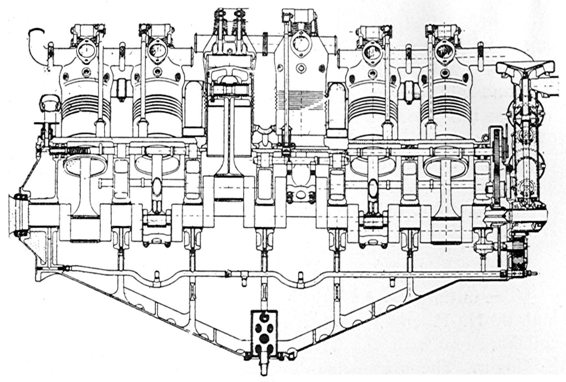
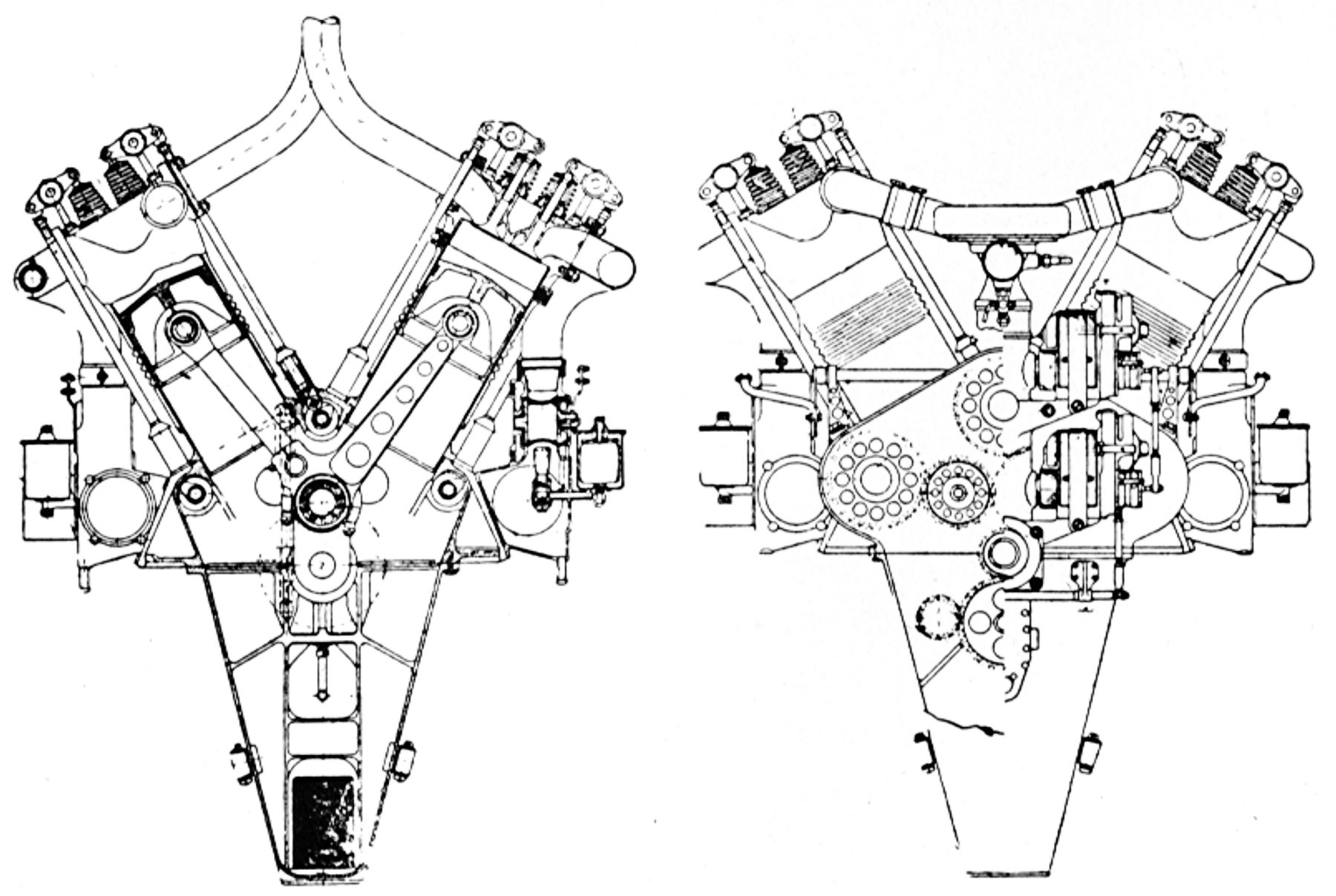
Bugatti engines were designed and built in France during WWI by Ettore Bugatti, a well-known automobile designer. The first engine was an eight-cylinder in-line with propeller reduction gearing. A sixteen-cylinder version was built with two in-line eights mounted upon the same crankcase and the two crankshafts geared to a common central propeller shaft, which was made hollow to permit the firing a French 37-mm cannon mounted between the cylinder banks. The French Government did not order either engine so Bugatti shipped both models to the United States. Tests showed structural weaknesses and a redesign of the sixteen-cylinder version commenced at Duesenberg Motors Corp., Elizabeth, NJ, under the direction of Charles B. King. The new engine proved to be much better than the original French-built model, so production was undertaken at once at Duesenberg. At the signing of the Armistice and production was stopped, forty of these engines had been tested and accepted by the U.S. Government. Postwar development and use was not seriously consideration.
 |
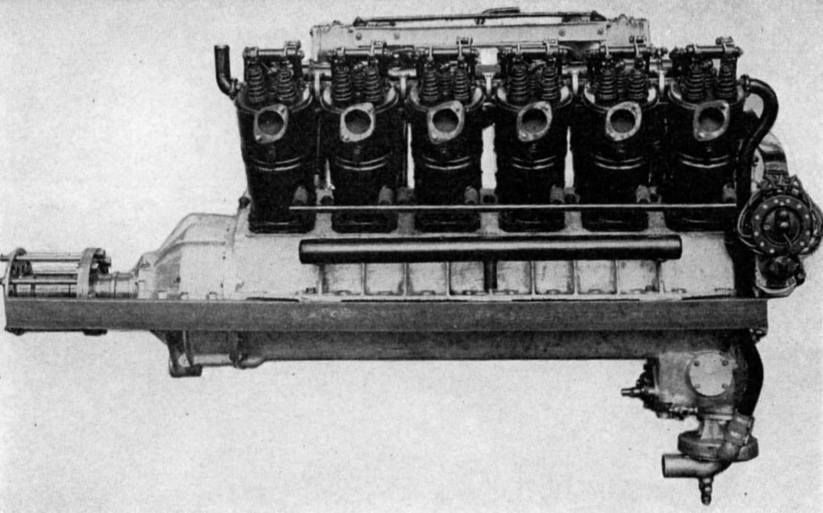
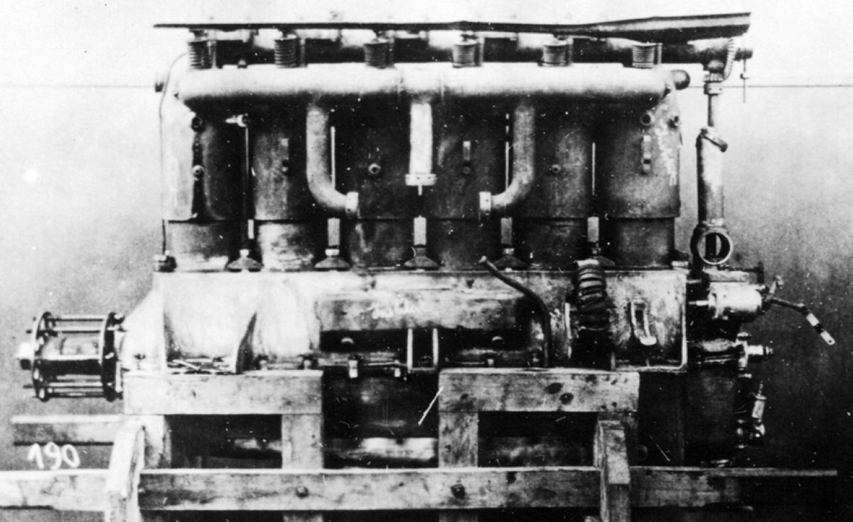
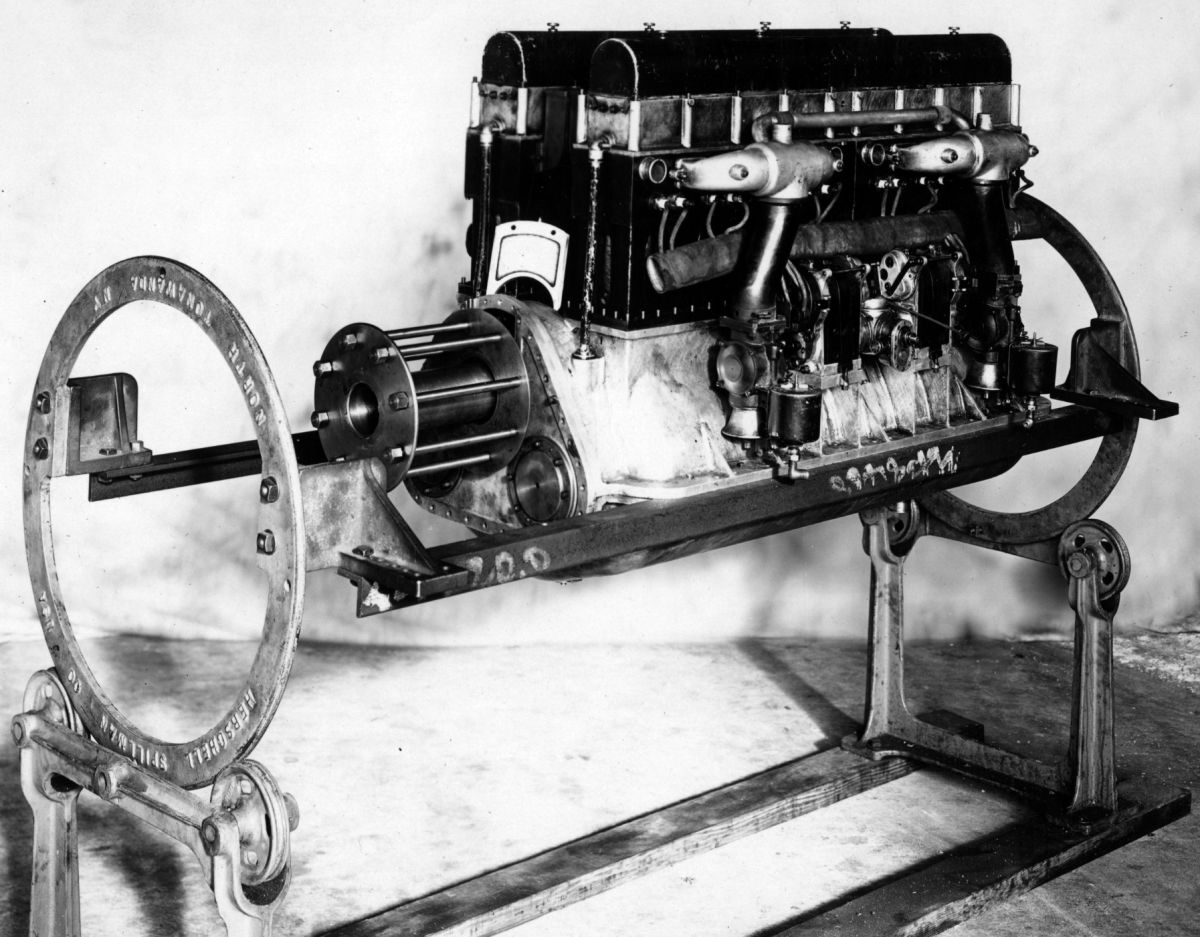
| Bugatti I-8 (AEE) |
The water-cooled vertical eight-cylinder Bugatti had a 110 mm (4.331") bore, 160 mm (6.299") stroke, 12.164 l (742.3 in³) displacement, and a 5:1 compression ratio. It normally developed 210 hp at 1,880 rpm and 250 hp at 2,160 rpm. Propeller reduction ratio via spur gearing was 47:32. Fuel consumption was 0.478 lb/hp/hr and oil consumption was 4 lb/hr. Either two Bugatti or two Zenith carburetors with 58-mm venturis, 210-cc main jets and 200-cc. compensating jets were used. A gear pump provided pressure lubrication. Cylinders were cast from iron in groups of four, and included a frame to which the sheet-iron or steel plates that formed the water jackets were screwed. A single overhead camshaft made in two sections was driven from the center by a vertical shaft and bevel gears. Two inlet valves and the one exhaust valve in each cylinder were operated by separate rocker arms. Inlet valve clear diameter was 35 mm (1.378") and exhaust valve diameter was 52 mm (2.047"). Both valves had 10° seats and were lifted 12 mm (0.472"). The hollow exhaust valve stems were cooled by air circulation. The inlet valve opened at top center and closed 45° late; the exhaust valve opened 45° early and closed 15° late. The crankshaft was built up from two conventional four-cylinder shafts coupled together at right angles by a tapered joint at the center main bearing. Plain bearings were provided on either side of a crank throw, hence there were nine main bearings. The propeller shaft was located above and to one side of the crankshaft center. By mounting the rear propeller shaft bearing on the crankcase side instead of forward in the usual manner, it was possible to keep the overall length to a minimum. The connecting rods had H-section shanks and the aluminum pistons had five rings. A centrifugal pump circulated cooling water, and two H-L-8 Bosch magnetos provided dual ignition . Dry weight was 485 lb.
The French sixteen-cylinder Bugatti vertical twin used cylinder banks from the eight-cylinder model. Its displacement was 24.328 l (1,484.6 in³) and rated 400 hp at 2,100 rpm. Dry weight was approximately 1,000 lb; the engine was 44.2" long, 24.8" wide, and 32.28" high. Two crankshafts similar those used in the eight-cylinder engine were geared to a common propeller shaft at a 3:2 ratio. Four Zenith carburetors, each mounted on a manifold feeding four cylinders, were located outside of the cylinder blocks. Four magnetos, two for each row of eight cylinders, furnished dual ignition.
 |
 |
 |
 |
 |
 |
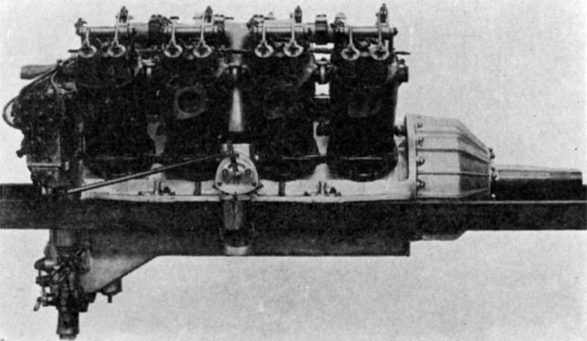
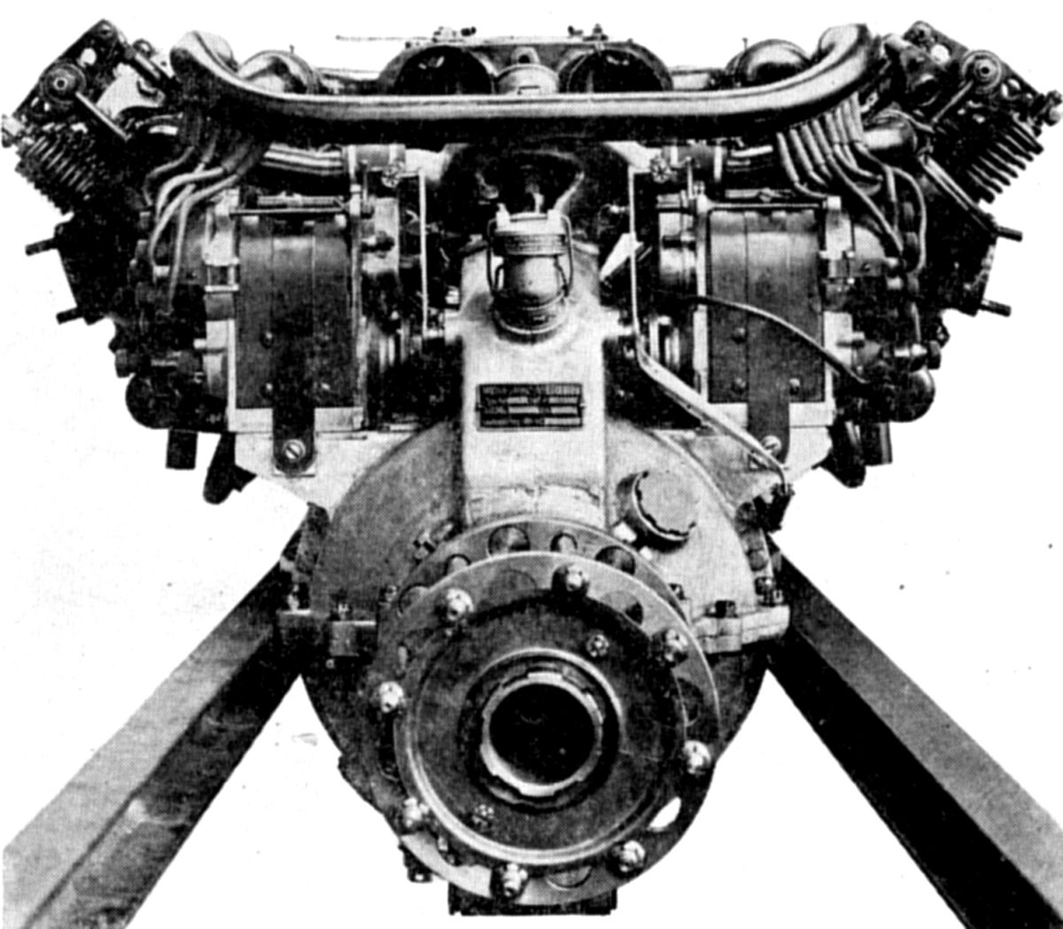
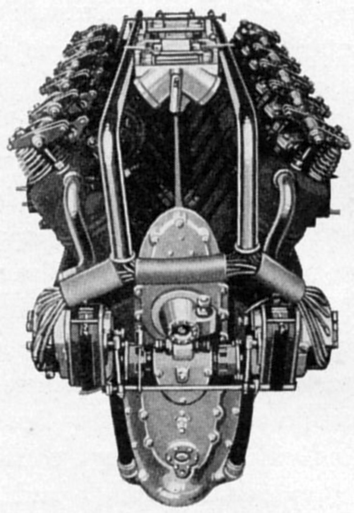
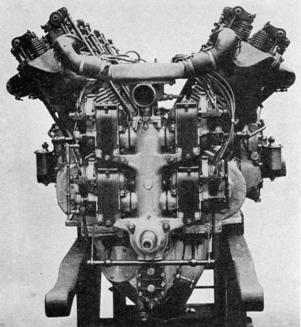
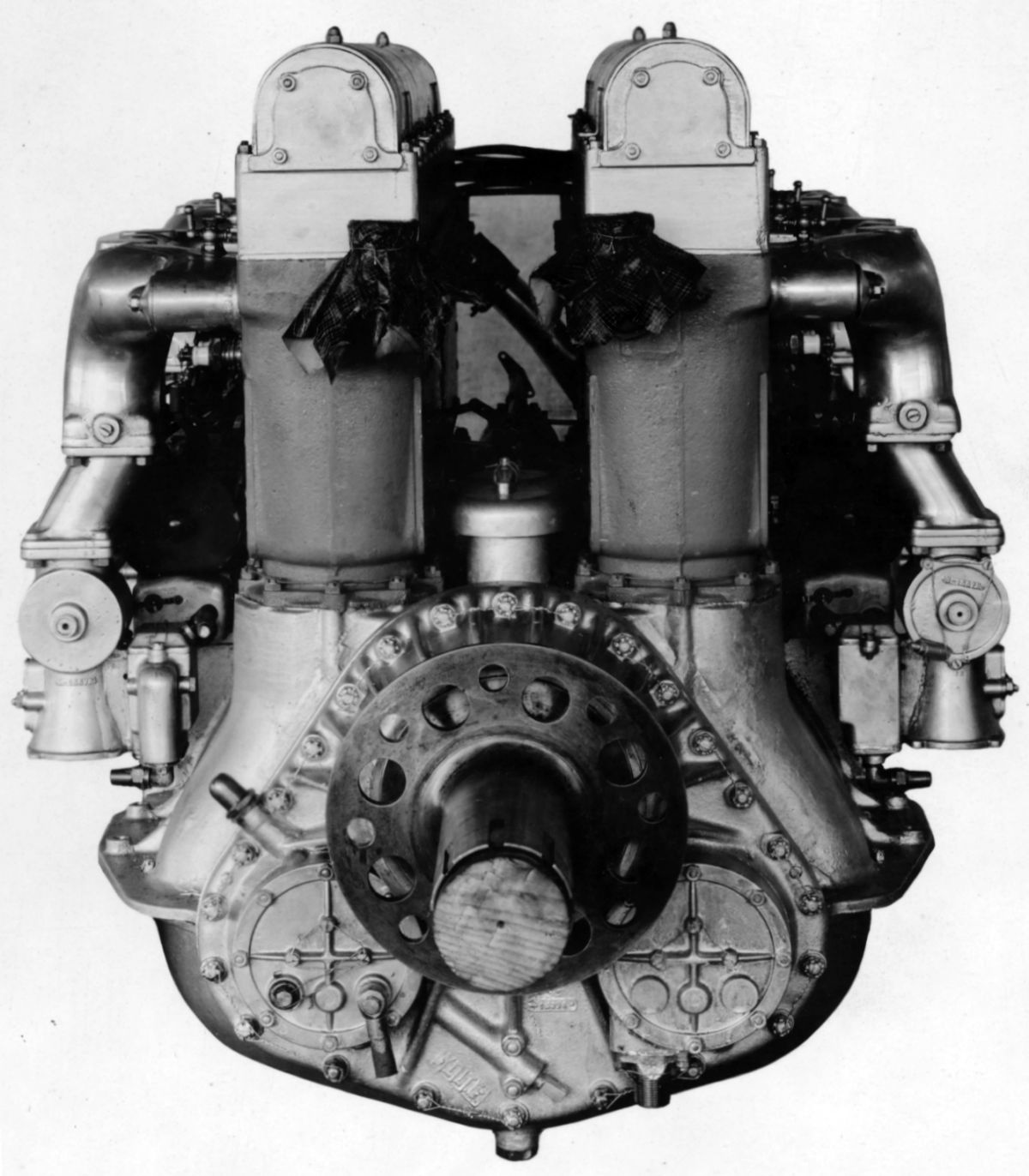
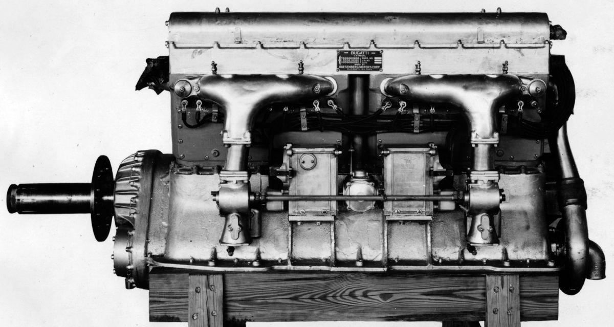
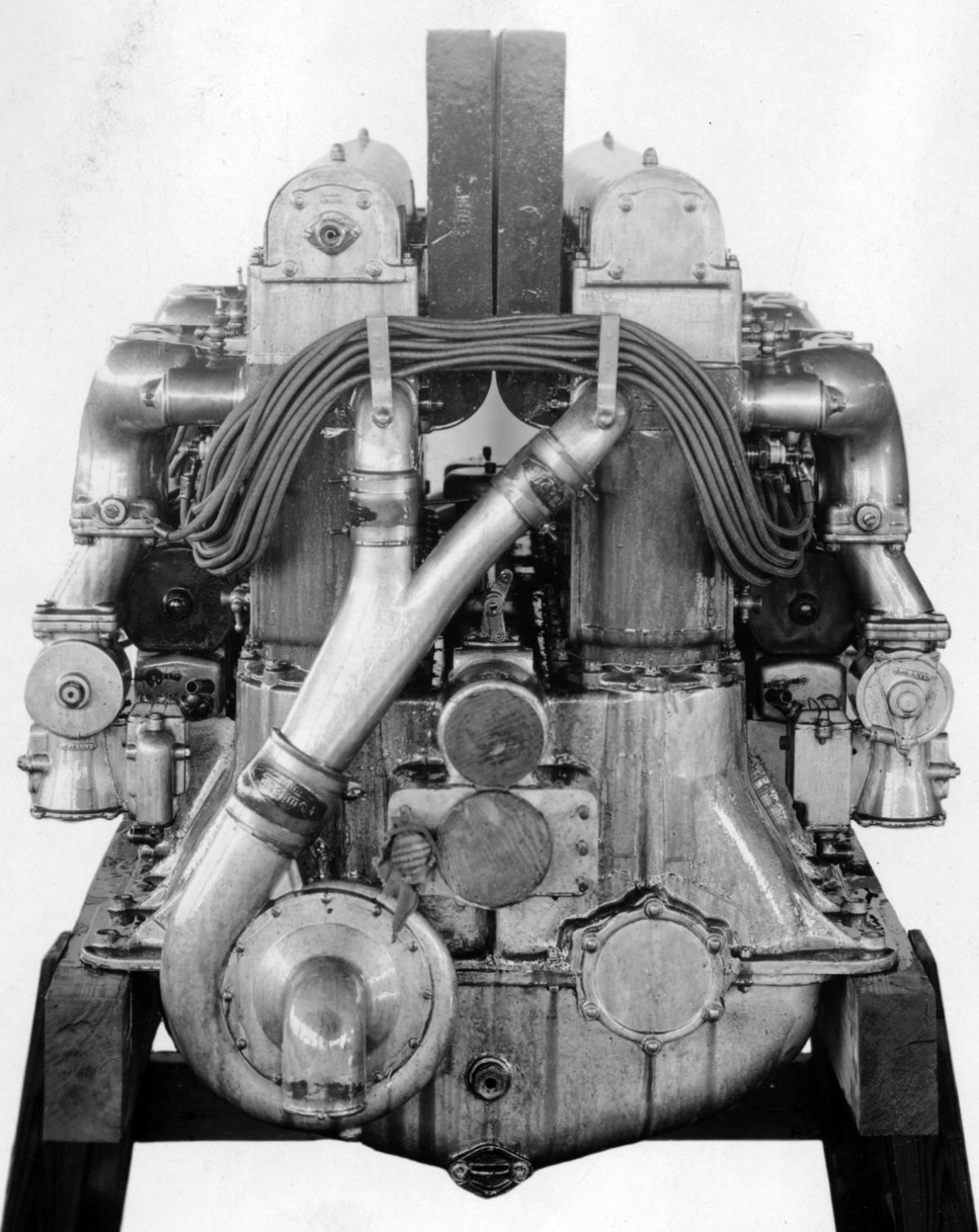
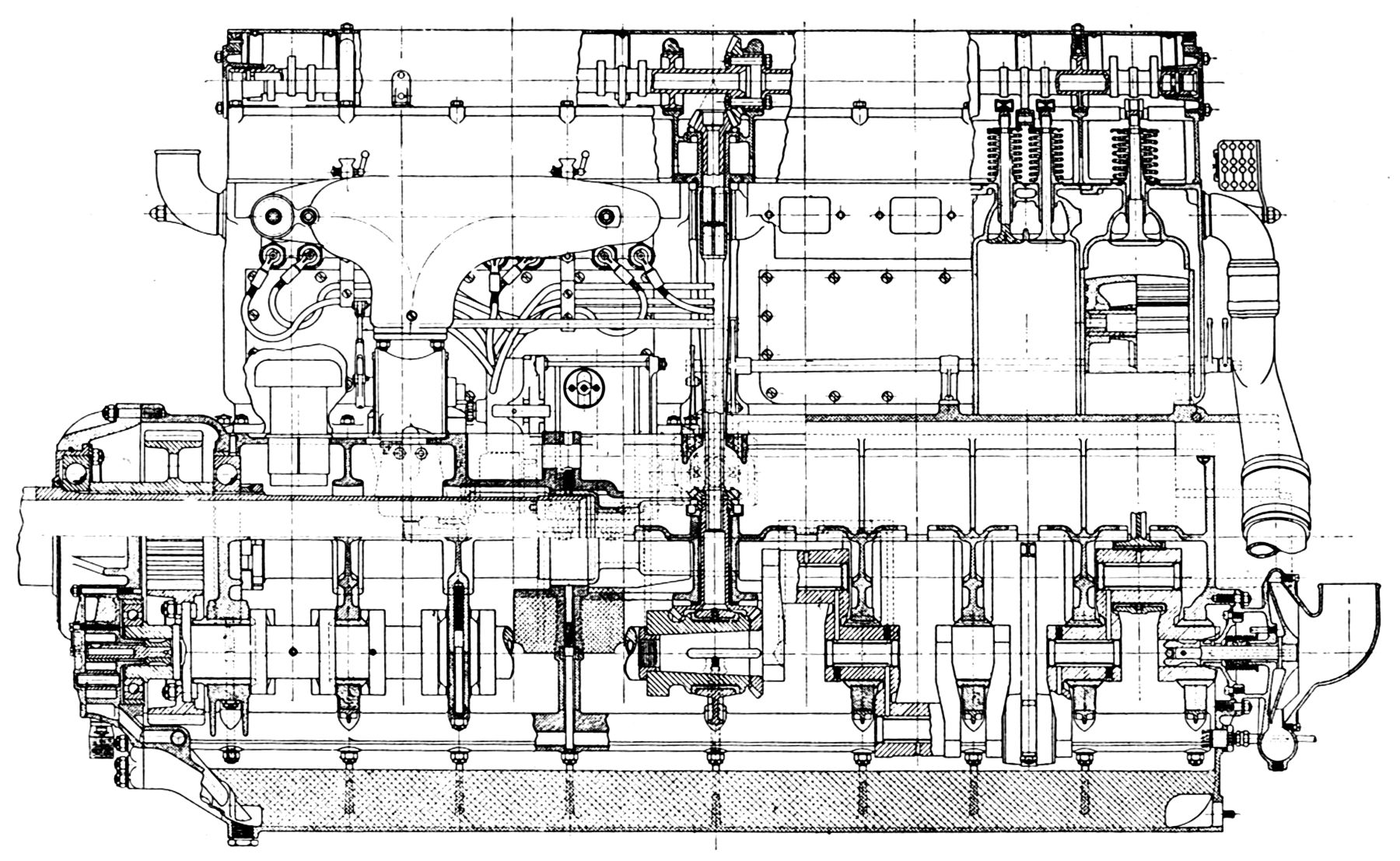
| King Bugatti U-16 (NARA, AEE) | |||||
An American version of the French sixteen-cylinder Bugatti design, known as the King-Bugatti U-16, was produced by the Duesenberg Motors Corporation under the direction of Charles B. King. This engine was rated at 420 hp and weighed 1,248 lb dry; cooling jacket water weighed an additional 38 1b. The principal dimensions and construction were practically the same as the original French model. However, a number of design improvements to the valves, propeller reduction gears, water pump, lubrication system, etc., were made. The ignition was changed to Splitdorf and Simms units with distributors mounted at the camshaft ends. Four Miller carburetors with the side float chambers. The water jackets were made of aluminum instead of sheet steel.
References
Angle, Glenn D, ed. Aerosphere 1939 (New York, New York: Aircraft Publications, 1940).
Anble, Glenn D, ed. Airplane Engine Encyclopedia (Dayton, Ohio: Otterbein Press, 1921).
Morse, William. Rotary Engines of World War One (Olney, England: Nelson & Saunders, 1987).
Nahum, Andrew. The Rotary Engine (London, England: Her Majesy's Stationary Office, 1987).
Image Sources: A39 = Aerosphere 1939; AEE = Airplane Engine Encyclopedia; NARA = U.S. National Archives and Records Administration; UKNA = United Kingdom National Archives.
Send mail to
![]() with questions or comments about this web site.
with questions or comments about this web site.
![]()