Selected Early Engines
Fairchild, Farcot, Farina, Farman, Fiat,
Fox
Compiled by Kimble D. McCutcheon
Published 7 Jun 2022; Revised 8 Jun 2022
Fiat
Giovanni Agnelli founded Societá Anonima Fiat in 1898 to develop and build all forms of terrestrial, marine and aerial locomotion. The name was derived from the initials of Fabbrica Italiana Automobile Turin. Modern manufacturing establishments at Lingotto and Mirafiori, Turin, Italy had devoted aircraft engines manufacture departments. Starting with motor vehicle construction, which soon gained world-wide recognition, Fiat gradually extended its manufacturing activities to include tractors, trucks, diesel marine engines, railway trucks, aircraft and aircraft engines. Fiat aircraft engine history is an important part of Italian aviation history. From the first engine of 1908 Fiat engines powered a substantial proportion of military and commercial Italian aircraft. Fiat produced over 15,000 aircraft engines during WWI, more than all other Italian manufacturers combined. These were mostly A.12bis and A.14 models. Following WWI, Fiat temporarily withdrew from aircraft engine activities, but these were revived and intensively pursued when the Fascist Regime gained power. This research and development program finally resulted in a series of water-cooled V-12s, air-cooled radial, compression-ignition engines, and in-line types for light aircraft. These engines figured prominently in air races, speed record., and long distance flights.
|
| SA8/75 (A39) |
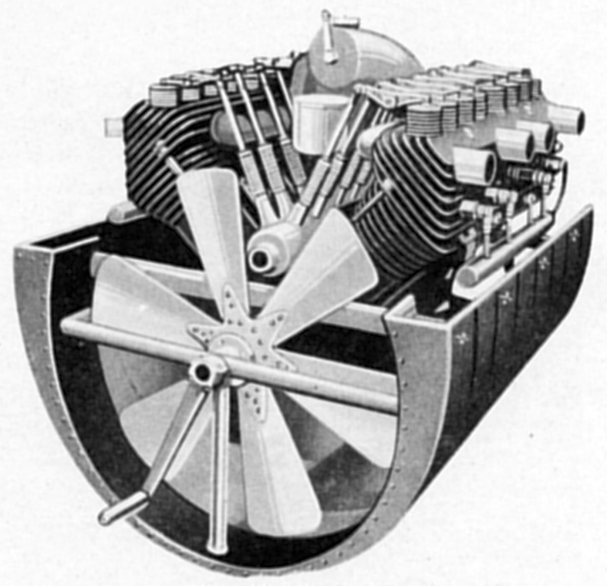
The SA8/75, Fiat's first aircraft engine, introduced in 1908, was an air-cooled 90° V-8, with a 75 mm (2.953") bore, 90 mm (3.543") stroke and 3.181 l (194.1 in³) displacement. It was rated 35 – 40 hp at 1,700 rpm and 50 hp at 2,000 rpm . One carburetor within the Vee fed all eight cylinders. A centrally located camshaft operated the valves via push rods and rocker arms. A separate magneto provided ignition for each four-cylinder row and a fan circulated cooling air.
 |
 |
| Airship Power Plant (A39) | S.55 (A39) |
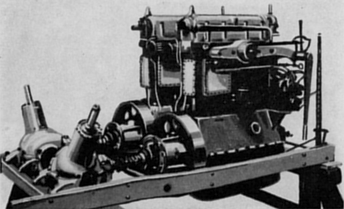
In 1910, Fiat turned its attention to water-cooled inline fours for Italian Military dirigibles. Two engines mounted side-by-side in a car drove remote propellers through a flywheel, clutch, shafts and gears. With a 110 mm (4.331") bore and 190 mm (7.480") stroke, each engine displaced 7.223 l (440.8 in³). A cast iron cylinder block had its coolant jacket openings covered by aluminum plates secured with numerous screws. The camshaft, fully enclosed in a housing bolted to the cylinder block top, was driven by a vertical shaft and bevel gears. A later water-cooled airship inline four had cylinders cast in pairs from iron. These featured a T-head where two valves on each cylinder side were operated directly from the camshafts located on each side of the cast aluminum crankcase upper section.
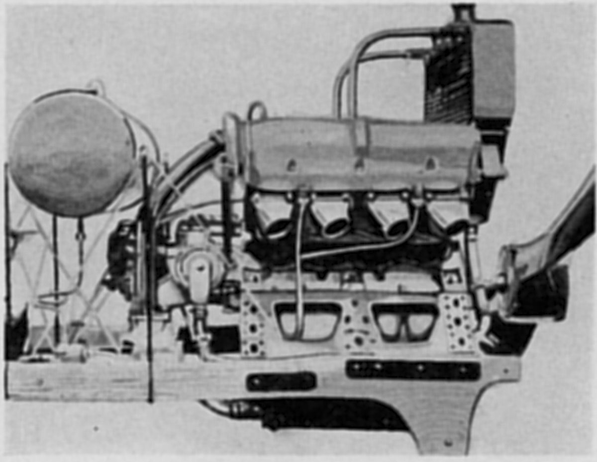
The S.55, a 1912 water-cooled V-8, had four valves per cylinder that were operated from a fully-enclosed overhead camshaft driven by a vertical shaft and bevel gears.
The A.10, a water-cooled vertical inline six was rated 100 hp at 1,400 rpm.
 |
 |
 |
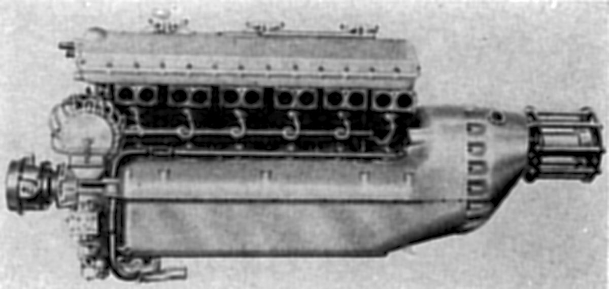
| A.12 (AEE) | A.12bis (AEE) | |
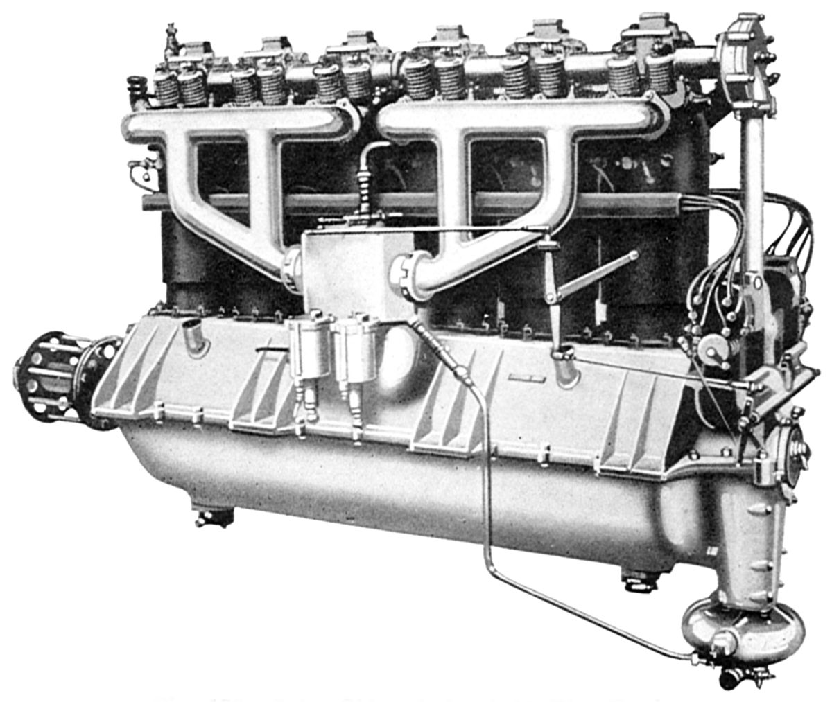
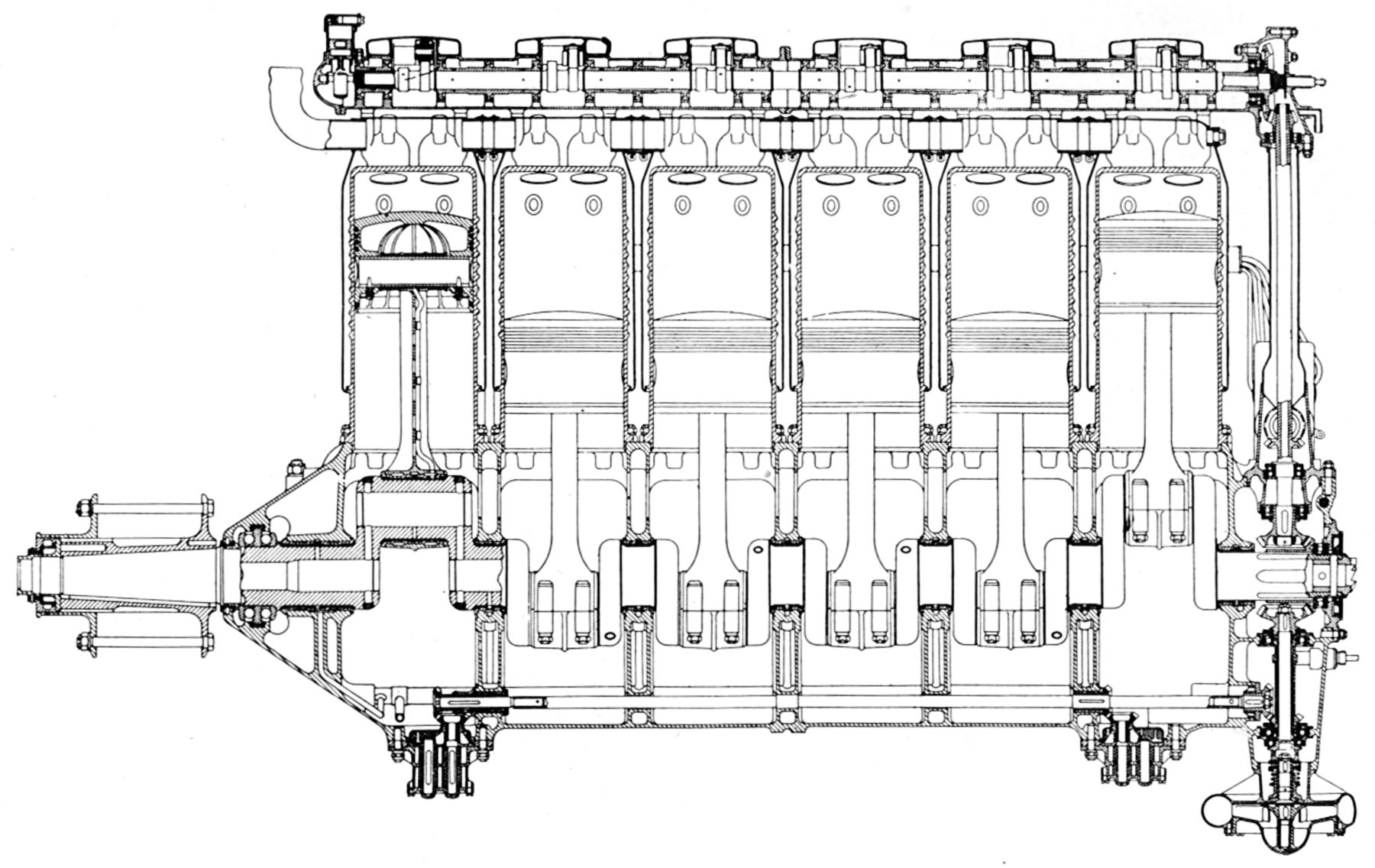
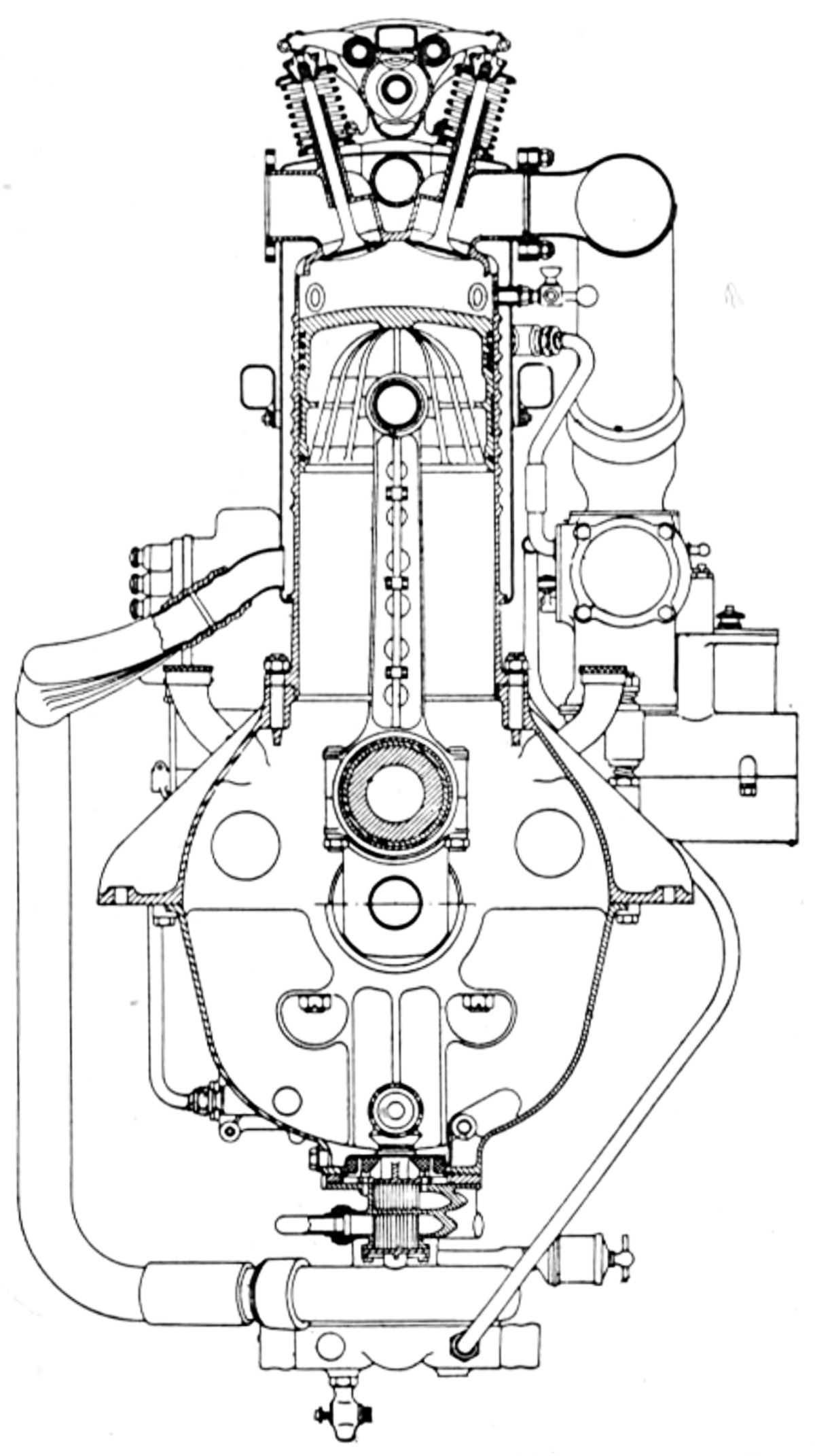
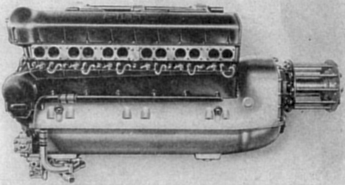
The A.12, introduced in 1916, was a water-cooled vertical inline six with a 160 mm (6.299") bore, 180 mm (7.087") stroke and 21.715 l (1,325.1 in³) displacement, that was guaranteed to deliver 225 hp at 1,300 rpm, 245 hp at 1,450 rpm, and 255 hp at 1,500 rpm. Fuel consumption was 0.492 lb/hp/hr, and oil consumption 0.024 lb/hp/hr. The cylinders were from individual steel forgings with integral head and barrel. The valve ports and water jackets were welded in place. Each cylinder had two inlet and two exhaust valves of 51.44 mm (2.025") clear diameter installed with the stems inclined to the cylinder axis. The inlet valve lift was 11.78 mm (0.464") and the exhaust valve lift was 11.328 mm (0.446"). An overhead camshaft supported in twelve beatings, operated each valve pair from a single cam and rockers. The camshaft was lubricated by packing the casing with heavy oil, which was sufficient for twelve hours running. The inlets opened 10° early and closed 50° late; the exhausts opened 45° early and closed 15° late. The double carburetors were water jacketed. An gear-type oil scavenge pump was located at each lower crankcase end; a gear-type pressure pump below the rear scavenging pump delivered pressurized oil to the bearings. The six-throw seven-main-bearing crankshaft used four-bolt H-section connecting rods with drilled webs to which an oil pipe feeding the piston pin was clipped. The aluminum pistons were fitted with four top compression rings, and one lower oil scraper ring. A centrifugal pump circulated the cooling water, and two high-tension Dixie magnetos furnished the ignition.
The A.12bis, a later 1917 A.12 development with identical dimensions but with a 4.75:1 compression ratio, new carburetors, new manifolds, and pressure-fed camshaft lubrication, was rated 300 hp at 1,600 rpm and could produce and 328 hp at 1,800 rpm. Fuel consumption ranged front 0.517 to 0.579 lb/hp/hr and oil consumption from 0.055 to 0.063 lb/hp/hr. Dry weight was approximately 920 lb, or 3.06 lb/hp; cooling water in the block added another 41 lb. The A.12bis was 71.811" long, 23.071" wide and 46.26" high.
 |
 |
 |
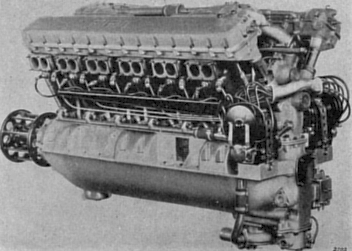
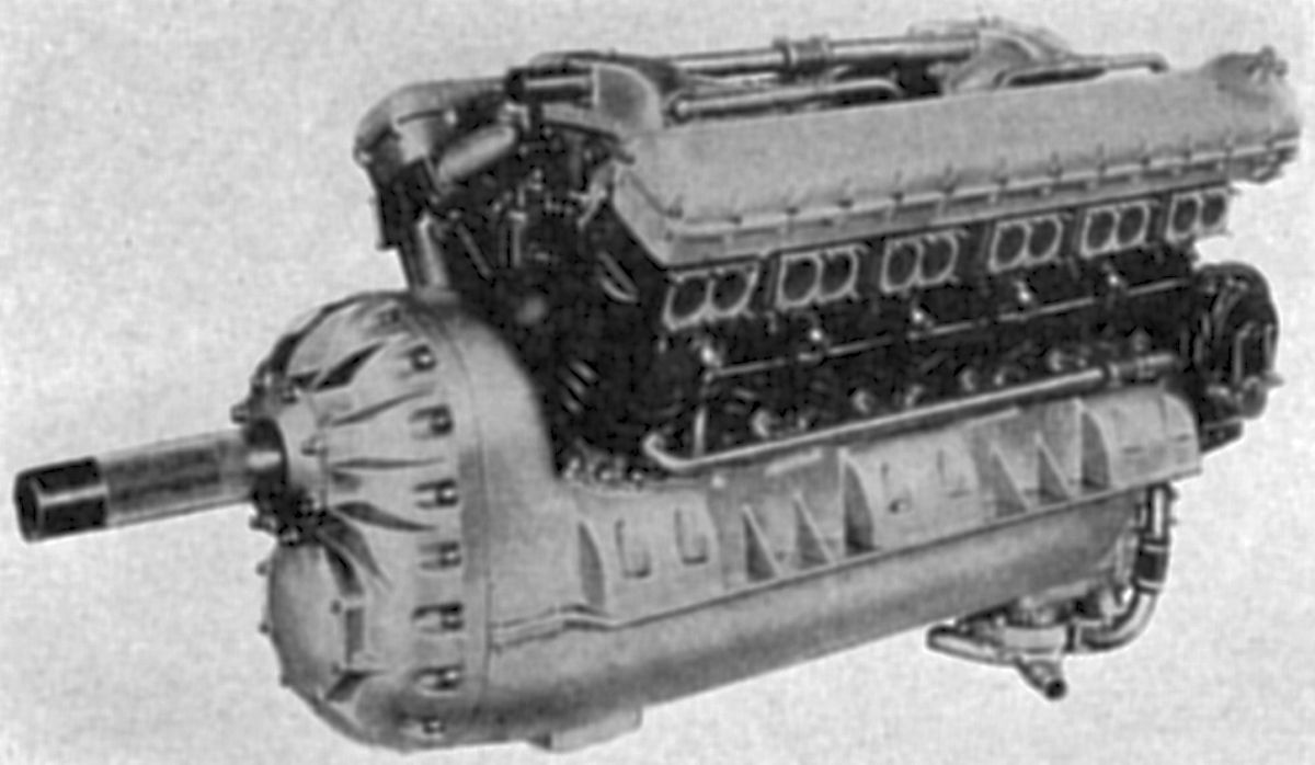
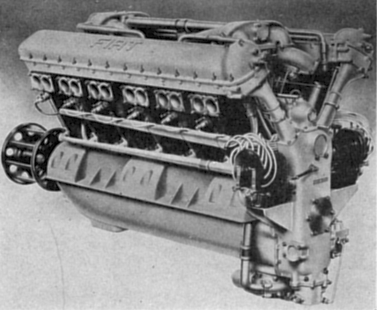
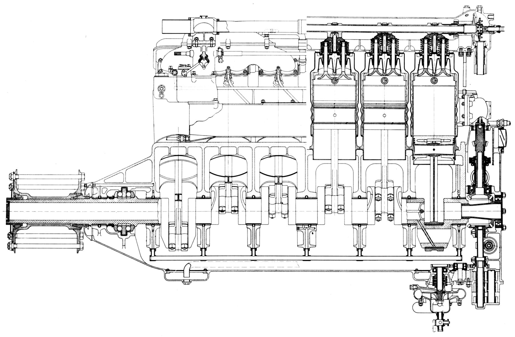
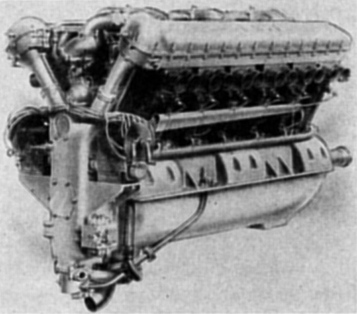
| A.14 (AEE) | ||
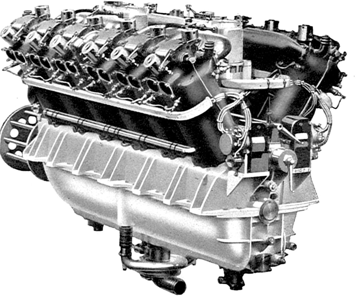
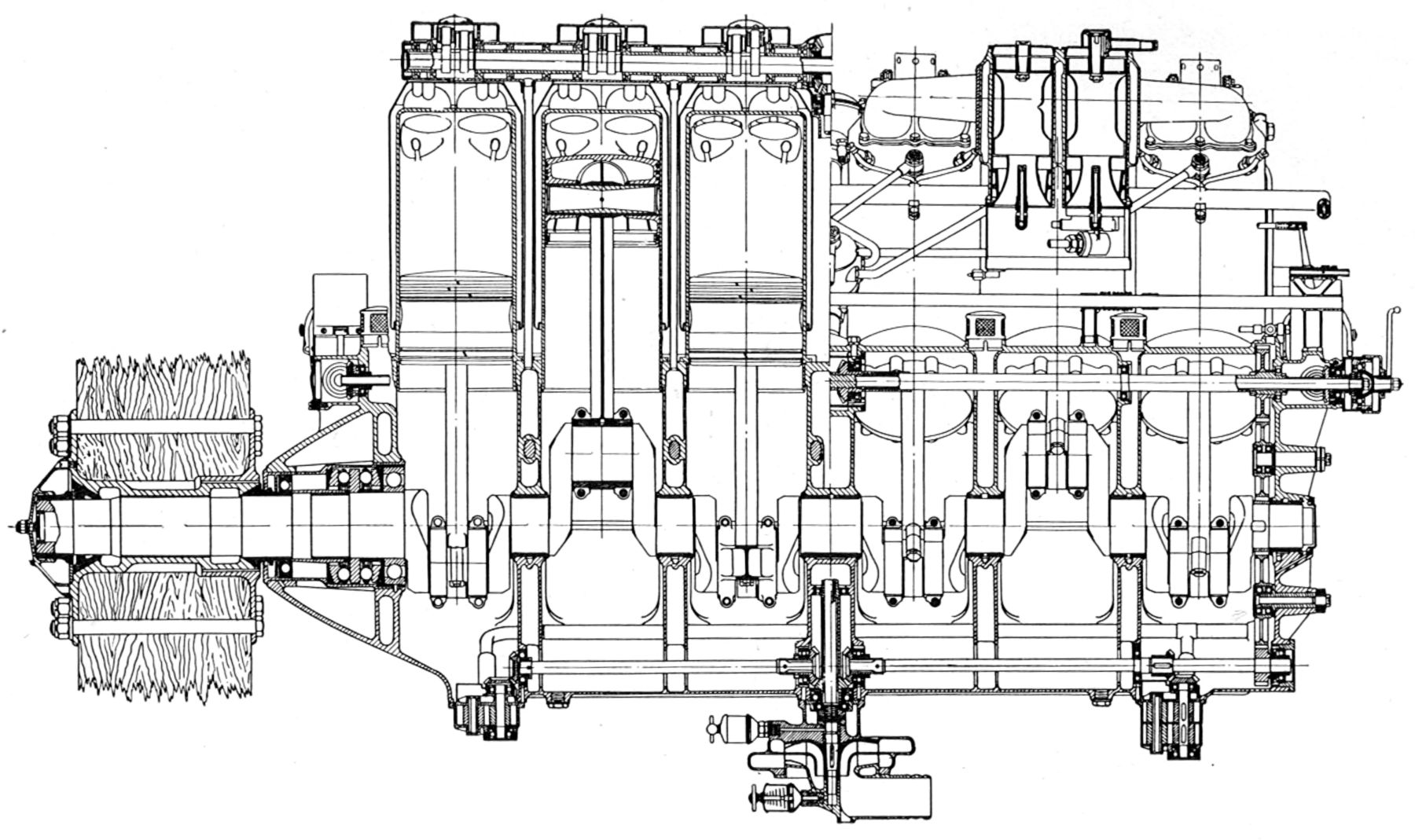
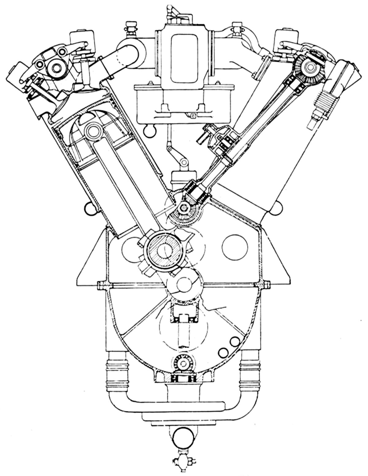
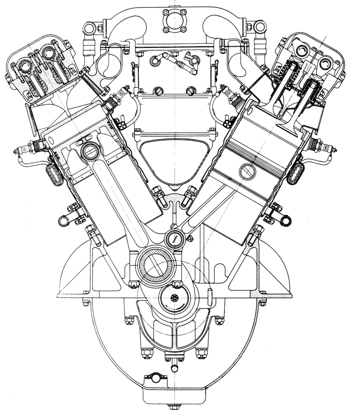
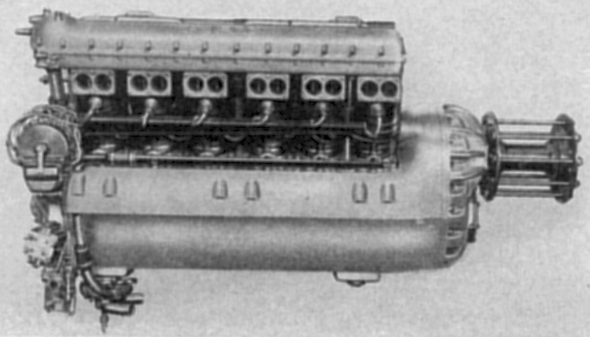
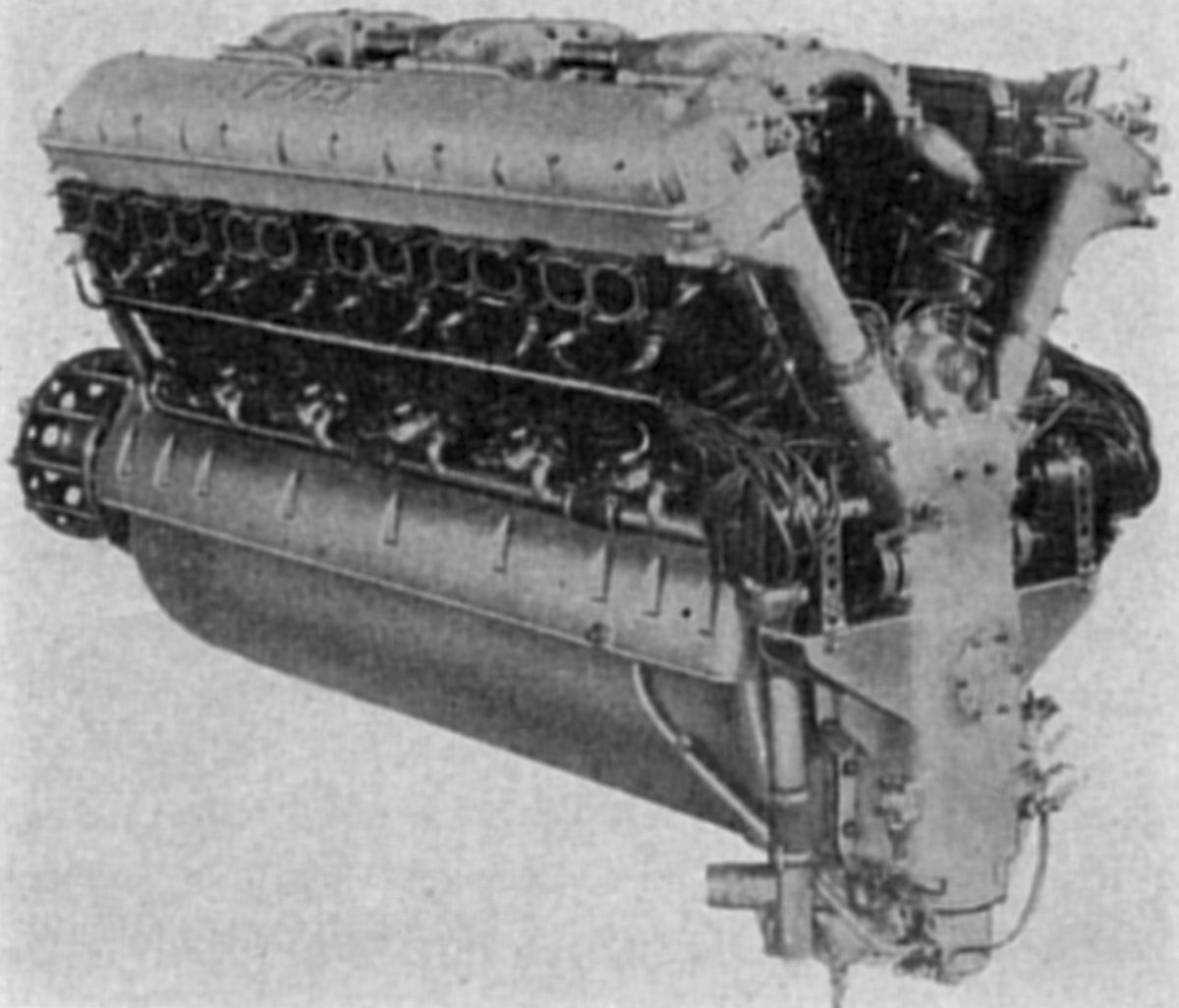
The A.14 was brought out experimentally in June 1917 and probably was used more in actual flight than any other European engine over 500 hp. A water-cooled 60° V-12, the A.14 had a 170 mm (6.693") bore, 210 mm (8.268") stroke, 57.199 l (3,490.5 in³) displacement, 4.967:1 compression ratio and 90 psi bmep. It produced 650 hp at 1,550 rpm, 685 hp at 1,650 rpm, and 725 hp at 1,730 rpm. The individual steel cylinders with barrels and heads integral had valve ports and water jackets welded in place. Two inlet and two 66.5 mm (2.618") diameter exhaust valves were inclined to the cylinder axis and operated in pairs from each cam by rocker arms. Two concentric springs between each valve pair were housed in a cup guided on a thin tubular post on the cylinder; it had lugs to receive the valve stem split washers. The inlet valves opened 8° late and closed 45° late; the exhaust valves opened 42° early and closed 5° late. The six-throw seven-main-bearing crankshaft used fork-and-blade connecting rods with H section shanks. Heavily ribbed aluminum pistons were fitted with three top compression rings and one lower oil-scraper ring. A centrifugal water pump, which ran at 1.5 times engine speed, circulated water via double outlets leading up through the crankcase to pipes connecting the cylinders. There were four spark plugs in each cylinder and ignition was provided by four six-cylinder Dixie magnetos. Two duplex Fiat carburetors were situated in the Vee. The front carburetor fed the front six cylinders and the rear carburetor fed the rear six cylinders. The lubrication system was similar to the A.12. Fuel consumption was 0.528 lb/hp/hr, and oil consumption 0.055 lb/hp/hr. Dry weight was 1,740 lb, or 2.67 lb/hp, and the trapped water added another 60 lb. The A.14 was 76.65" long, 37.4" wide, and 48.78" high.
 |
| A.15 (AEE) |
The A.15, an experimental water-cooled 60° V-12 of 1917, had a 110 mm (4.331") bore, 150 mm (5.906") stroke, 17.106 l (1,043.9 in³) displacement. Rated at 300 hp at 2,400 rpm, its 3:2 propeller reduction gear featured a hollow propeller shaft through which a gun in the Vee could be fired. The A.15R, a later engine with larger bore, followed the same general construction form.
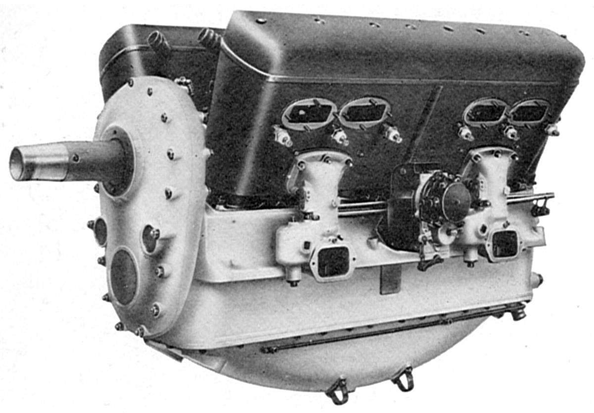
The A.15R, a water-cooled 60° V-12, introduced in 1917 with a 120 mm (4.724") bore, 150 mm (5.906") stroke, 20.357 l (1,242.2 in³) displacement and 5.5:1 compression ratio was rated 400 hp for long runs, and 430 hp 2,415 rpm for short runs. The propeller shaft was driven through herring-bone gears and nominally turned 1,600 rpm. Six forged steel cylinders were formed in a single block with a common welded-in-place sheet steel water jacket. An enclosed overhead camshaft, driven at its center, operated two inlet and two exhaust valves per cylinder with the exhaust stacks outside the Vee. Four carburetors attached to the cylinder block exterior with the mixture passing through welded-in passages to an external manifold in the Vee. A six-throw seven-main-bearing crankshaft and aluminum pistons were used. A pressure-fed lubrication system was used, along with two magnetos mounted crosswise at the engine center, outside in a very accessible position. Fuel consumption was 0.485 lb/hp/hr and oil consumption was 0.055 lb/hp/hr. The A.15R weighed approximately 800 lb, was 58.19" long, 28.89" wide and 31.69" high.
The A.16, a water-cooled 60° V-12 with a 145 mm (5.709") bore, 160 mm (6.299") 31.705 l (1,934.7 in³) displacement, was rated 600 hp at 2300 rpm and employed gearing that reduced the propeller speed to 1,600 rpm.
 |
| A.18 (AEE) |
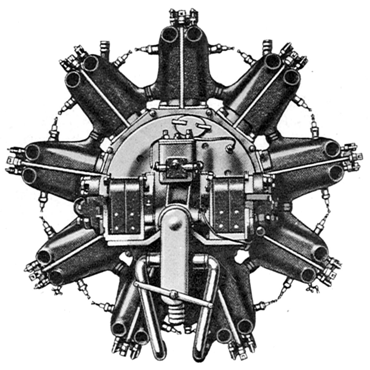
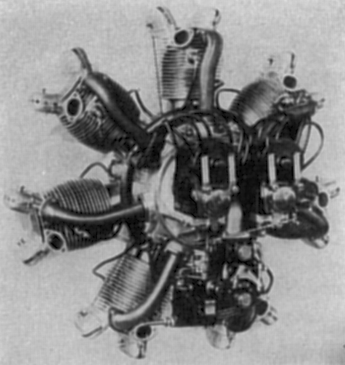
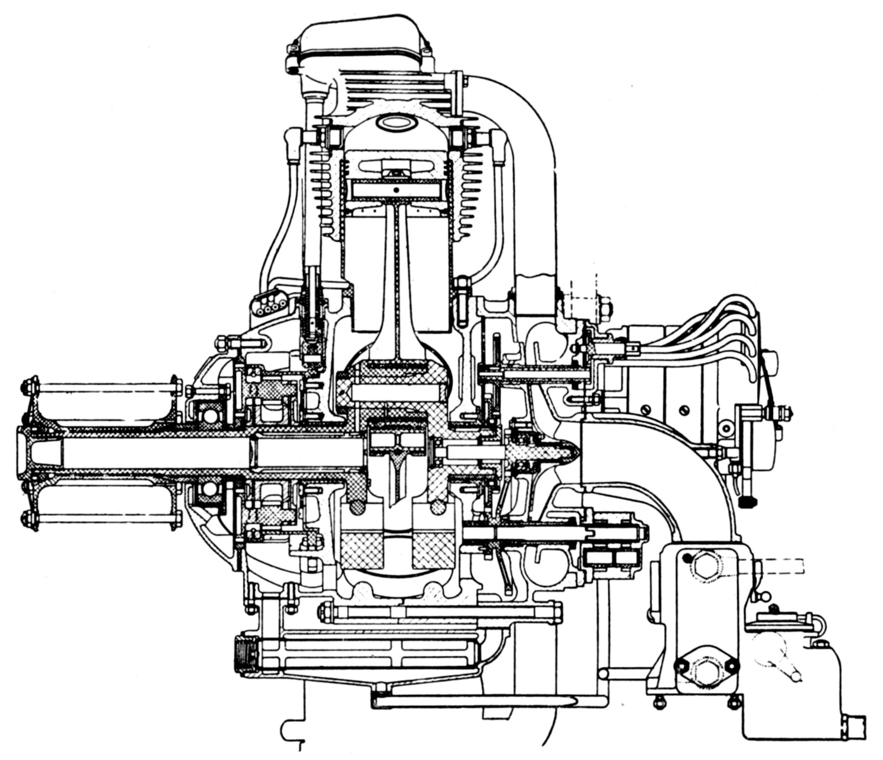
The A.18, introduced in 1917, was a water-cooled nine-cylinder radial with a 130 mm (5.118") bore, 150 mm (5.906") stroke, 17.919 l (1,093.5 in ³) displacement rated 300 hp. at 1,800 rpm, and 320 hp at 2,000 rpm. Its steel cylinders had welded-on water jackets. The steel tubing inlet pipes were welded inside the water jackets and met with the crankcase induction chamber in the at the cylinder flange. The water jackets were connected together so that cooling water entered the lower two cylinder heads and discharged at the two cylinders on each side of the upper center cylinder. Two inlet and two exhaust valves standing vertically in the cylinder head were held to their seats by leaf springs and operated from a single plate cam by a push/pull rod and forked rocker arm. The single-throw built-up crankshaft, and the master connecting rod assembly, were both carried on ball bearings. The aluminum crankcase contained a passage for the induction charge provided by a single carburetor. Two spark plugs, placed diagonally in each cylinder in a horizontal position, were connected to separate magnetos mounted crosswise at the rear. A double-piston pump circulated the oil, and a centrifugal pump the cooling water. The A.18 weighed 500 lb empty and 546 lb with water, had a 39.4" diameter and 22.4" length.
 |
| Fiat Two-Stroke (A39) |
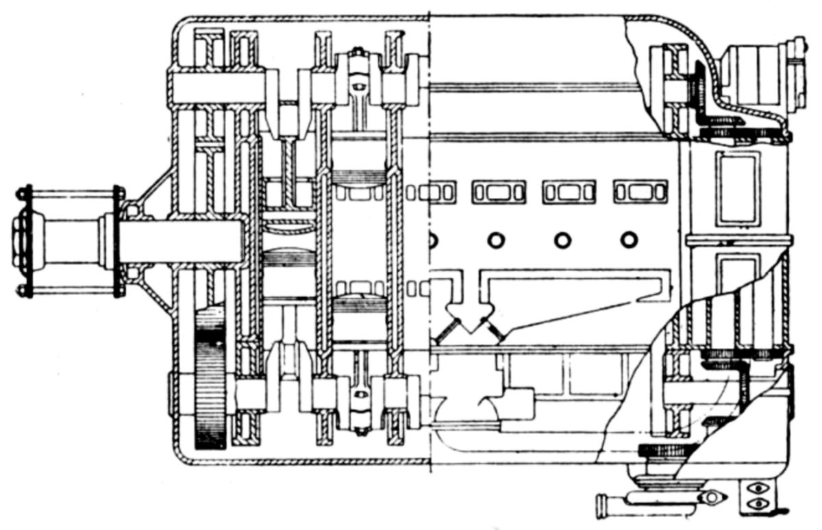
Fiat developed a two-stroke engine, primarily for racing cars but with consideration toward aircraft as well. Six parallel horizontal cylinders, each containing two pistons, were connected to crankshafts at opposite cylinder ends. A spur gear train connected the two crankshafts to a central propeller shaft. A supercharger, located at the anti-propeller end was driven from through bevel gearing.
In 1925 Fiat discontinued all previous models and introduced a new water-cooled 60° V-12 line. Cylinders were machined from steel forgings and had welded-on valve ports and top plate, as well as sheet-steel water jackets. Four vertical valves in each cylinder were operated by two overhead camshafts. The camshafts were geared together and supported by bearings in a split aluminum casing that bolted to each cylinder head. A bevel gear attached to one camshaft end was driven by a vertical drive shaft. Identical cams on each side of a camshaft bearing acted upon the top of a T-shaped bridge that was guided vertically, and whose underside operated each valve pair. Six-throw, seven-main-bearing crankshafts were supported on babbitt-lined bronze plain bearings. A deep-groove ball thrust bearing was used in some direct-drive engines. Articulated connecting rods with H-section shanks were attached to aluminum-alloy trunk type pistons that were cam-ground to compensate for differential expansion at working temperature. Two compression rings and two oil scraper rings, located above and below the piston-pin, were included on each piston. The aluminum crankcase sections were joined along the crankshaft centerline, and the main bearing duralumin caps were held by four bolts each. Most auxiliary drives were contained in a case bolted to the engine rear end. Two Marelli MF 12 magnetos mounted crosswise supplied dual ignition. These were driven through bevel gears from the upper vertical shaft that also drove the inclined camshaft drive shafts. The lower vertical shaft drove the oil pump and water pump through a spur idler gear, and a fuel pump through a horizontal shaft with a worm gear. Duplex carburetors located in the Vee typically supplied three cylinders from each throat. A dry-sump lubrication system was employed.
 |
| A>20 (A39) |
The A.20, introduced in 1925, had a 115 mm (4.528") bore, 150 mm (5.906") stroke, 18.696 l (1,140.9 in³) displacement and 5.8:1 compression ratio. Its output was 210 hp at 2,060 and 440 hp at 2,200 rpm. The higher-compression A.20S, with a 6.2:1 compression ratio developed 510 hp at 2,400 rpm. Both the A.20 and A.20S weighed 734 lb. The high altitude A.20A, with an 8.0:1 compression ratio, was rated 410 hp at 2,200 rpm, but could momentarily produce 550 hp at 2,400 rpm; it weighed 738 kb. All three A.20 series engines were 57.7" long, 27.57" wide and 36.08" high.
 |
 |
 |
 |
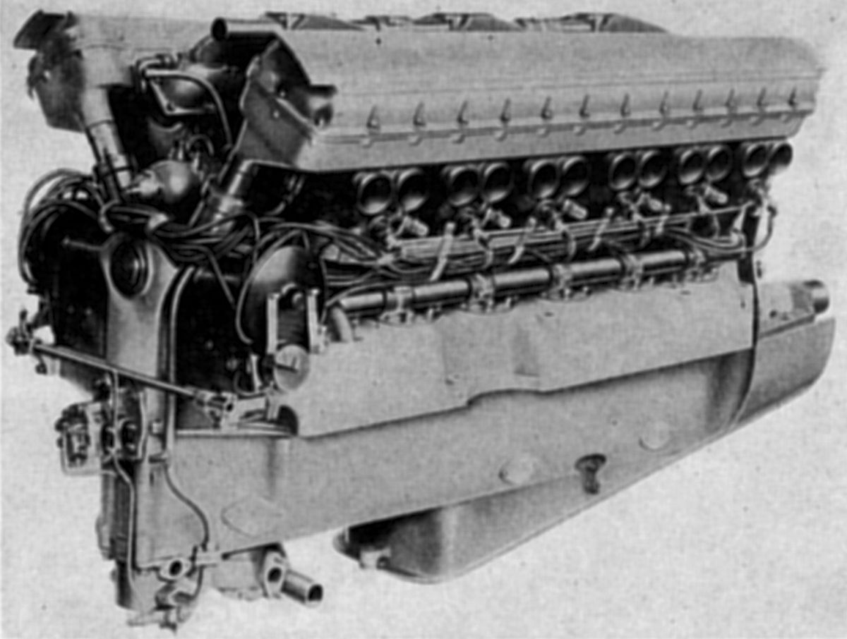
| A.22 (A39) | |||
The A.22 direct-drive engine series, introduced in 1927, had a 135 mm (5.315"), 160 mm (6.299") bore and 27.843 l (1,699.1 in³) displacement. The A.22T, with a 5.6:1 compression ratio, developed 550 hp at 1,900 rpm and 590 hp at 2,000 rpm; it weighed 1,014 lb. The A.22S, with a 6.1:1 compression ratio, developed 580 hp at 1,900 rpm and 625 hp at 2,100 rpm; it weighed 926 lb. The high-altitude A.22A, with a 7.5:1 compression ratio, delivered 570 hp at 1,900 rpm and 750 hp at 2,100 rpm for short periods. It weighed 1,023 lb with an aluminum crankcase and 935 lb with an Elektron (magnesium alloy) crankcase. Fuel consumption for all three types was 0.517 lb/hp/hr. These engines were 63.71" long, 28.33" wide and 40.72" high.
A.22 series engines were also built with 1.545:1spur propeller reduction gears. The A.22R normal compression ratio engine, introduced in 1929, produced 580 hp at 2,100 rpm. The high-altitude A.22RAQ produced 560 hp at 1,950 rpm and 700 hp at 2,100 rpm for short periods. Both engines weighed 1,149 lb, were 69.92" long, 28.33" wide and 40.75" high.
 |
| A.24R (A39) |
The 1929 A.24 had a 140 mm (5.512") bore, 175 mm (6.890" ) stroke, 32.327 l (1,972.7 in³) displacement and 5.7:1 compression ratio. It produced 700 p at 2,000 rpm, 750 hp at 2,200 rpm, and the direct-drive version was 64.17" long, 28.94" wide, 41.38" high and weighed 1,092 lb . Fuel consumption was 0.528 lb/hp/hr. With a 1.5457:1 propeller reduction gear ratio, the A.24R weighed 1,195 lb dry and 12.15 lb more with water, was 69.69" long. 28.94" wide and 41.93" high. The A.24Rbis weighed 1213 lb dry and had a 0.496 lb/hp/hr fuel consumption.
 |
| A.25 (A39) |
The A.25, introduced in 1928 with a 170 mm (6.693") bore, 200 mm (7.874"), 54.475 l (3324.3 in³) displacement and 5.2:1 compression ratio, produced 950 hp at 1,700 rpm and 1,050 hp at 1,900 rpm. Dry weight was 1,874 lb, fuel consumption was 0.528 lb/hp/hr, length was 79.33", width was 36.02" and height was 48.48". Pintor and Colangeli used this engine to win the 1931 Prince Bibescu Trophy.
 |
| A.26R (A39) |
The A.26R, a 1.5456:1 ratio geared version introduced in 1929 with the same bore and stroke as the A.24, was rated 720 hp at 2,000 rpm and 760 hp at 2,200 rpm. Fuel consumptions was 0.496 lb/hp/hr and oil consumption was 0.022 lb/hp/hr. Dry weight was 1,210 lb, 1,275 lb with water, fuel and oil in the engine. It was 70.94" long, 29.72" wide and 40.74" high.
 |
| A.30R (A39) |
The A.30R, a geared engine with a 1.6367:1 ratio introduced in 1931, had a 135 mm (5.315") bore, 140 mm (5.512") stroke, 24.047 l (1,467.4 in³) displacement, 8:1 compression ratio, and a 166.29 psi maximum bmep. Its normal rating was 600 hp at 2,600 rpm from ground level to 2,500 m (8,202 ft) and three-minute maximum of 850 hp at 2,900 rpm. Fuel consumption was 0.496 lb/hp/hr and oil consumptions was 0.022 lb/hp/hr. Its dry weight was 1,027 lb, 1063 lb with water, fuel and oil. It was 68.94" long, 25.71" wide and 36.82" high. The A.30R had smaller frontal area and higher operating speed than most other geared Fiat designs. Cassinelli and Scapinelli used it to win the Dal Molin Trophy in 1932. The A.30RA, a later A.30R version using 88 octane fuel, had the same rating, although the fuel consumption was 0.513 lb/hp/hr and oil consumption was 0.033 lb/hp/hr. Dry weight was 1,060 lb.
The A.33RC was practically identical with the A.30RA except that the compression ratio was 6:1 and a supercharger turned at 9.48 times crankshaft, maintaining 700 hp at 2,600 rpm up to 3,500 ft. The A.33RC fuel consumption was 0.6 lb/hp/hr and it weighed 1,102.4 lb.
The AS.2 was a water-cooled V-12 was used by Major Bernardi in his Macchi M 39 seaplane that won the Schneider Trophy Race of 1926. Its bore was 140 mm (5.512"), stroke was 170 mm (6.693") and displacement 31.403 l (1,916.3 in³).
 |
| AS.3 (A39) |
The AS.3, a water-cooled direct-drive V-12, was developed for the 1927 Schneider Trophy Race and was used by Major Bernardi in 1928 to set a world's seaplane record of 318.62 mph. With a 145 mm (5.7091") bore, 175 mm (6.890") stroke, 34.667 l (2,115.5 in³) displacement and 6:1 compression ratio, it developed 970 hp. With a 7:1 compression ratio it produced 1,000 hp at 2,500 rpm and 1,030 hp at 2500 rpm. It weighed 857 lb dry, 35 lb more when internal fluids were considered. It was 62.91" long, 28.33" wide and 39.49" high. The AS.3 followed standard Fiat construction except that babbitt was applied directly to the master connecting rod and the pistons were magnesium forgings.
 |
| AS.5 (A39) |
The AS.5, developed for the 1929 Schneider Trophy Race, was similar to the AS.3, but was a smaller engine operating at higher speeds to deliver the same output. With a 138 mm (5.433") bore, 140 mm (5.512") stroke, 25.128 l (1,533.4 in³) displacement and 8:1 compression ratio, it developed 1000 hp at 3,300 rpm and 1,050 hp at 3,300 rpm. It weighed 723 lb dry, and 750 lb with cooling water. It was 65.94" long, 25.39" wide and 32.28" high.
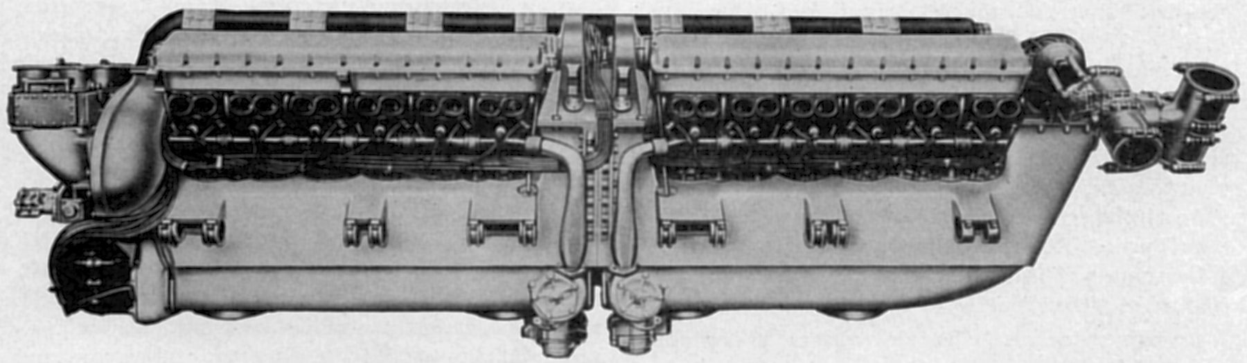 |
| AS.6 (A39) |
The AS.6, "Agello's" engine, a further racing program engine developed in 1932 – 1933 was a water-cooled 60° V-24 with its cylinders mounted in two rows on a light-alloy crankcase consisting of two units joined to a central double gearcase. Each V-12 group had an independent crankshaft fitted with a spur gear that meshed with a gear in the central gear case and drove a propeller shaft. The two coaxial propeller shafts were mounted in the Vee and revolved in opposite directions and drove two co-axial propellers, positioned one behind the other at the engine front at a 1.667:1 ratio. A large supercharger at the engine rear drew mixture from a single eight-throat down-draft carburetor and delivered it to both groups of cylinders through a long induction pipe in the Vee. With a 7:1 compression ratio, its output was 2,800 hp at 3,200 rpm, 3,100 hp at 3,300 rpm, and its dry weight was 2,050 lb. The AS.6 bore and stroke were the same as the AS.5, resulting in a 50.256 l (3,066.8 in³) displacement. Fuel consumption was 0.551 lb/hp/hr. It was 132.48" long, 27.64" wide and 38.43" high.
The AN.1 was a water-cooled diesel inline six that Fiat introduced in 1930. With a 140 mm (5.512") bore, 180 mm (7.087") stroke, 16.625 l (1,014.5 in³) displacement and 100 psi bmep it produced 180 hp at 1,600 rpm and 220 hp at 1,700 rpm. Dry weight was 892 lb. Except for a higher compression ratio, atomizers instead of spark plugs, and fuel pumps in place of the magnetos, the engine was almost the same as the A.12 bis. The individual forged steel cylinders were surrounded by welded-on sheet-steel water jackets. Two inlet and two exhaust valves were symmetrically arranged in the cylinder head and actuated by two overhead camshafts carried in an aluminum housing. Pistons and crankcase were made of aluminum alloy. Each Bosch fuel pump consisted of three pump chambers and the Bosch atomizers were in the cylinder sides at the usual spark plug position. An airplane powered by this engine made a flight front Turin to Rome in June 1930, with Renato Donati at the controls, the first flight in Italy credited to a diesel engine.
 |
 |
| A.50 (A39) | |
The A.50, introduced in 1929, was Fiat's first air-cooled radial. With seven cylinders, a 100 mm (3.937") bore, 120 mm (4.724") stroke, 6.597 l (402.6 in³) displacement, 5:1 compression ratio and 273 lb dry weight, it produced 85 hp at 1,600 rpm and 95 hp at 1,800 rpm. Fuel consumption was 0.50 lb/hp/hr and oil consumption 0.044 lb/hp/hr. Its diameter was 35.7" and its length 30.7". The cylinder barrels, machined from steel forgings, were screwed and shrunk into aluminum-alloy cylinder heads with hemispherical combustion chambers. Bronze valve seats were shrunk in place. Interchangeable inlet and exhaust valves were inclined 29° to the cylinder axis and operated in cast-iron guides. Each valve was fitted with two coil springs and operated via a push rod and rocker arm from a single plate cam. Both valve ports faced aft. Two compression rings and two oil scrapers were fitted to the aluminum alloy pistons. The two-piece crankshaft was joined at the crankpin and rode on two plain steel-back centrifugal1y-cast white-metal-lined bearings and fitted with a ball bearing that carried propeller thrust loads. Both master and link connecting rods were machined all over from steel drop forgings. The piston pins were fixed in the connecting rods, as were the link rod knuckle pins that rode in bronze bushings pressed into the master rod big end. The crankcase was split vertically in the cylinder plane and held together by long bolts, four of which extended aft for mounting. The front half contained cam driving gears while the aft half contained radial induction passages, the oil pump, carburetor, and magnetos. An oil sump was attached to the lower crankcase side. Dry-sump lubrication used gear pumps for both pressure and scavenging. A Zenith C-1361 carburetor, whose body was warmed by scavenge oil, supplied the mixture. Two Marelli M.F.7 magnetos provided dual ignition.
The A.50S, an A.50 with a higher 5.5:1 compression ratio, produced 100 hp at 1,800 rpm and 105 hp at 2,000 rpm. Fuel consumption was 0.508 lb/hp/hr and oil consumption was 0.013 lb/hp/hr. Dry weight was 291 lb, diameter was 35.43" and length was 32.32".
 |
| A.53 (A39) |
The A.53 was a redesigned A.50 introduced in 1931. With a 105 mm (4.134") bore, 120 mm (4.724") stroke , 7.274 l (443.9 in³) displacement and 5.5:1 compression ratio, it produced 115 hp at 1,900 rpm and 120 hp at 2,000 rpm. Fuel consumption was 0.508 lb/hp/hr and the dry weight was 326 lb. While the A.53 cylinders were similar to the A.50's, bronze valve guides replaced the earlier cast iron ones. The engine was started by charging the cylinders with a pressurized combustible mixture using a hand pump and distributor. The charge was fired on the power stroke by a small hand magneto. A centrifugal blower was added to insure good mixture distribution and to obtain a slight supercharging effect. The impeller was mounted in the rear housing co-axial with the crankshaft, and it was driven from the crankshaft through a gear train at a higher rotation speed. The carburetor, which fed the mixture into the center of this blower, was heated by scavenge oil.
Fiat continued producing progressively more refined seven, nine, fourteen and eighteen cylinder air-cooled radials, including the Pratt & Whitney Hornet A under license, through the 1930s and into the 1940s. These geared and direct-drive engines introduced provisions for constant-speed propellers, hydraulic pumps, and shielded ignition.
References
Angle, Glenn D, ed. Aerosphere 1939 (New York, New York: Aircraft Publications, 1940).
Anble, Glenn D, ed. Airplane Engine Encyclopedia (Dayton, Ohio: Otterbein Press, 1921).
Image Sources: A39 = Aerosphere 1939; AEE = Airplane Engine Encyclopedia; Flt = Flight Magazine; NARA = U.S. National Archives and Records Administration; UKNA = United Kingdom National Archives.
Send mail to
![]() with questions or comments about this web site.
with questions or comments about this web site.
![]()