Selected Early Engines
Fairchild, Farcot, Farina, Farman, Fiat, Fox
Compiled by Kimble D. McCutcheon
Published 28 May 2022; Revised 8 Jun 2022
|
|
|
|
| Prototype (A39) | Section (A39) | Operation (NARA) | 447-A (NARA) |
Fairchild
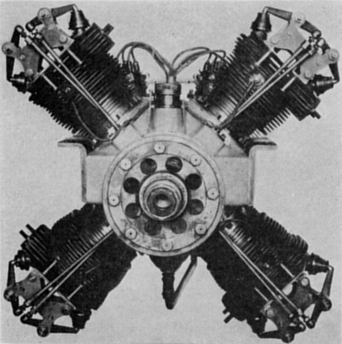
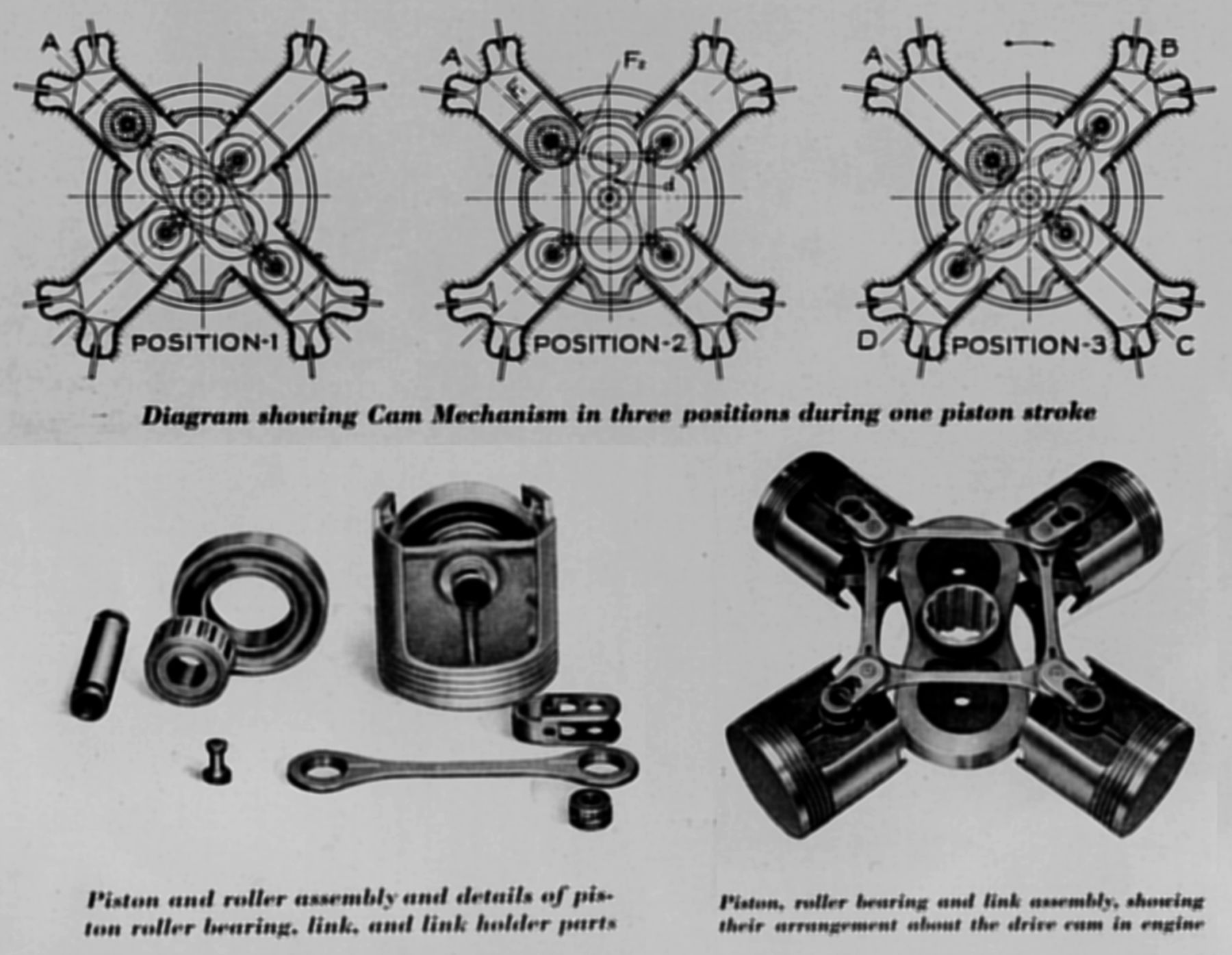
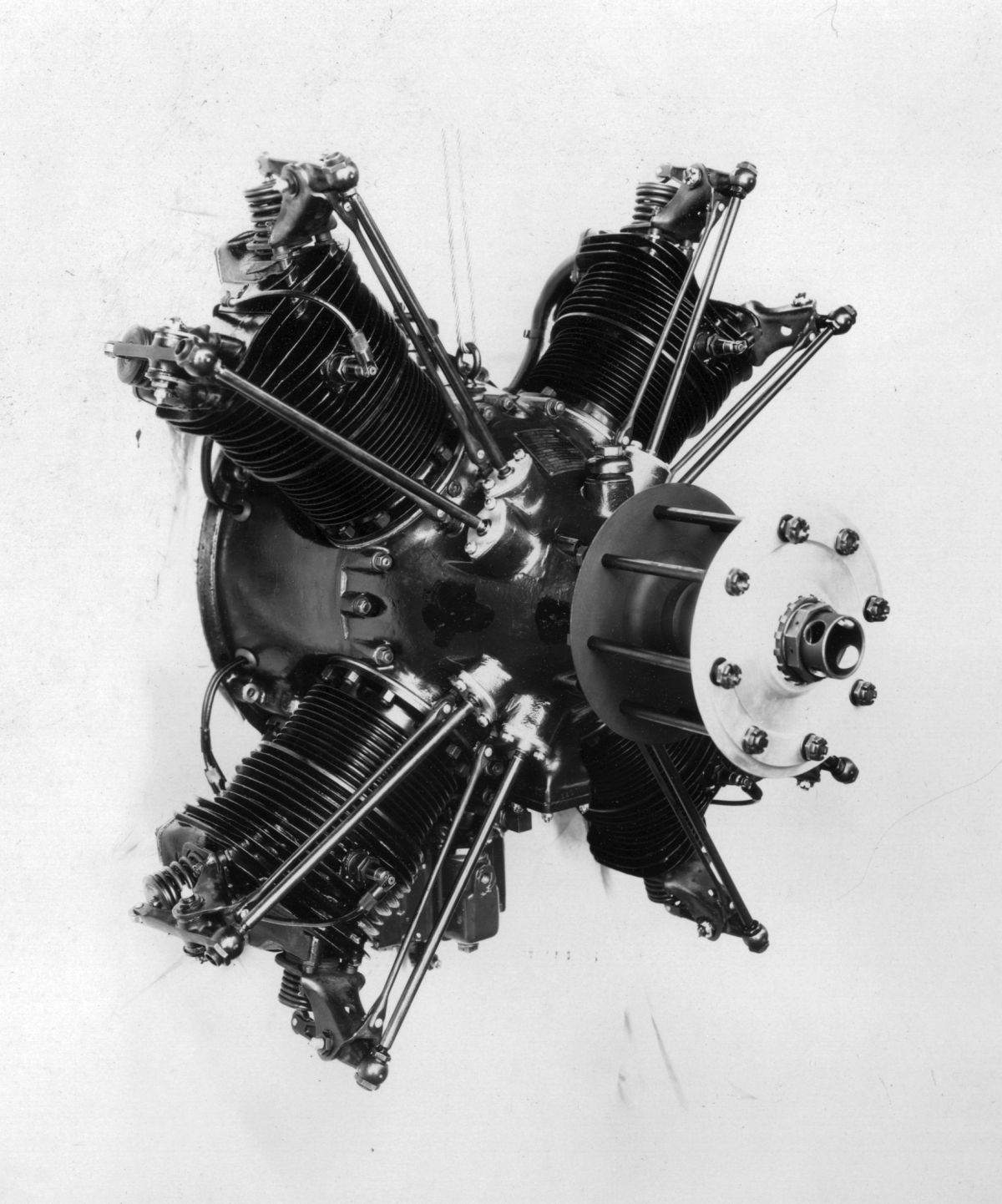
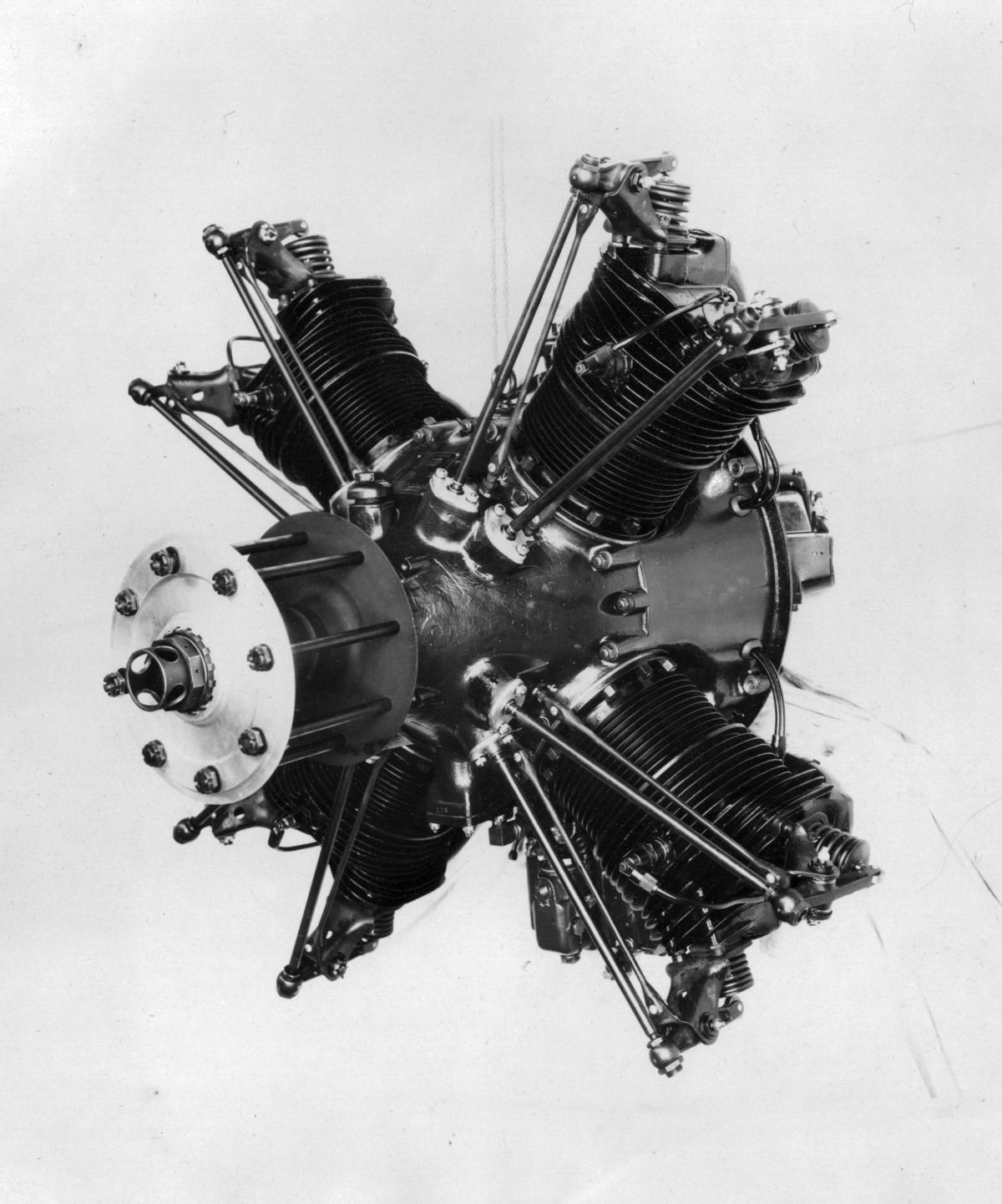
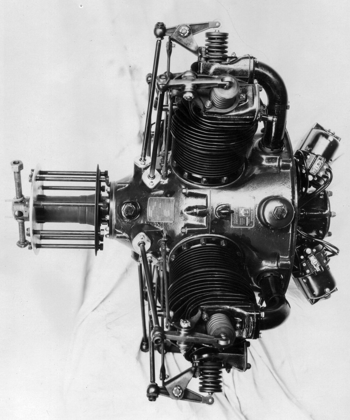
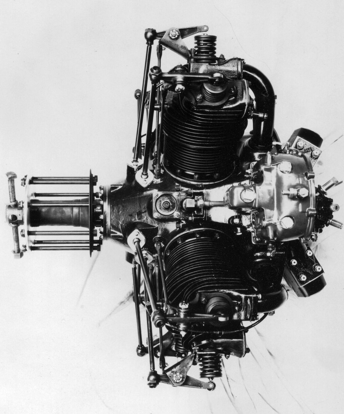
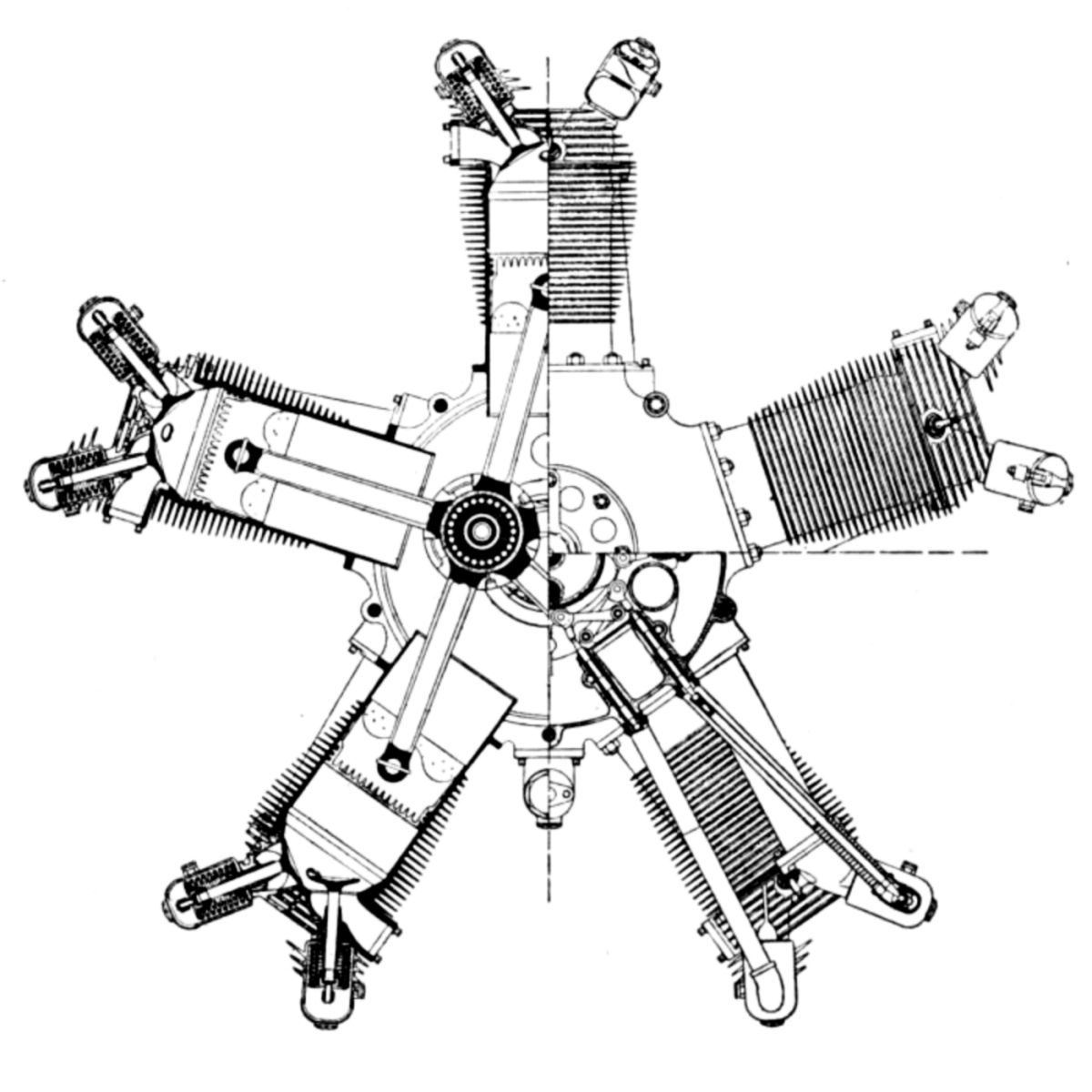
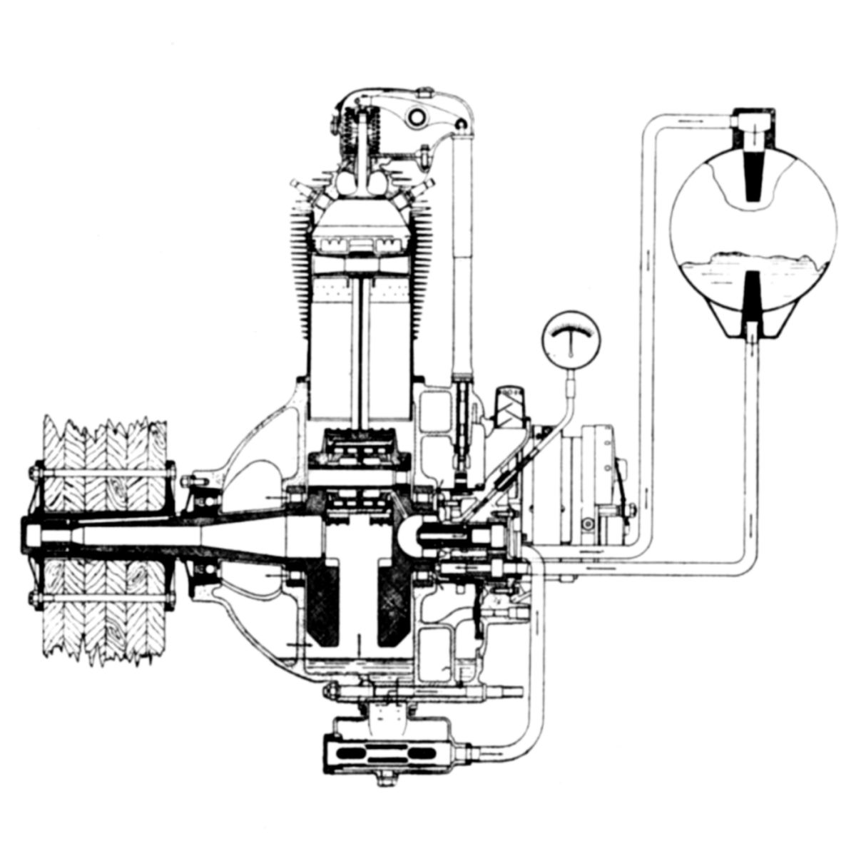
During the early 1920s, while working at the U.S. Army Air Service Engineering Division at Wright Field, Dayton, Ohio, Harold Caminez designed and built a novel air-cooled four-cylinder radial that used a cam mechanism to convert reciprocating piston motion into rotary motion. Rollers in the pistons operated upon a double-lobed cam on the main shaft. The piston rollers were kept in contact with the cam by means of link rods that formed a parallelogram. The two cam lobes caused each piston to make four strokes - one complete cycle - during each main shaft revolution, resulting in a greater output and a propeller rotating at half the speed of conventional direct-drive engines. As the piston motion in opposing cylinders was identical, inertia forces were always in theoretical balance, and there was no need for counterweights.
In 1925, Caminez found an industry backer and the Fairchild-Caminez Engine Corporation was formed. Located at Farmingdale, Long Island, New York, along with the Fairchild Aerial Camera Corporation and other Fairchild interests, this organization further developed the Caminez engine.
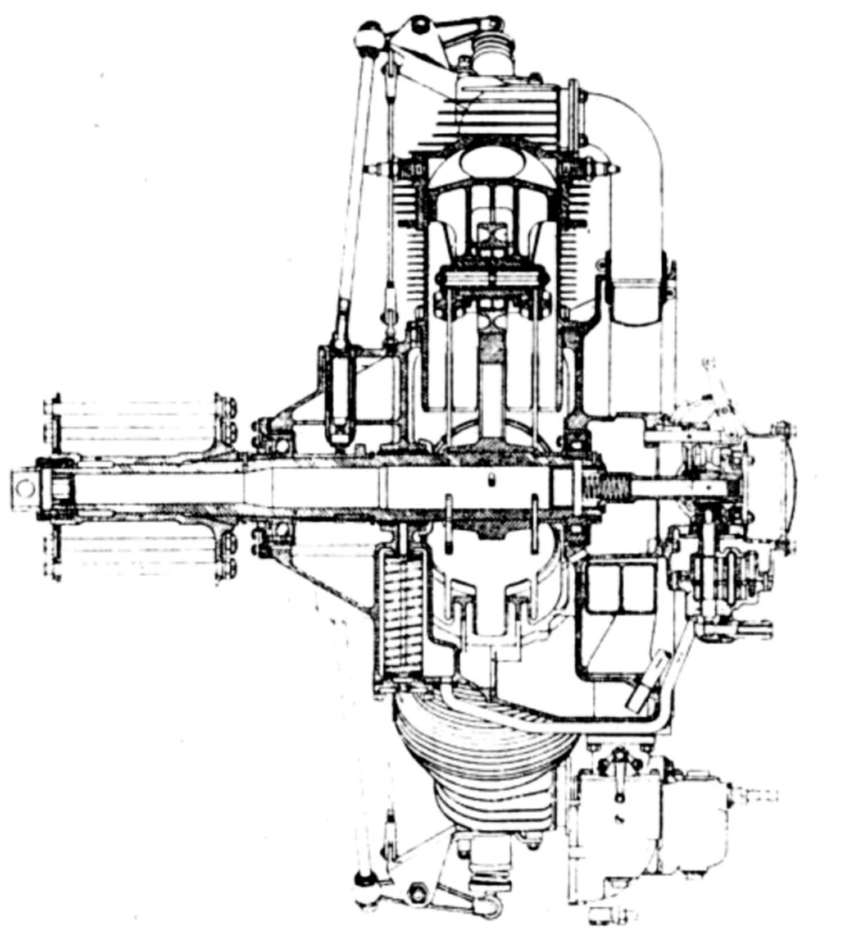
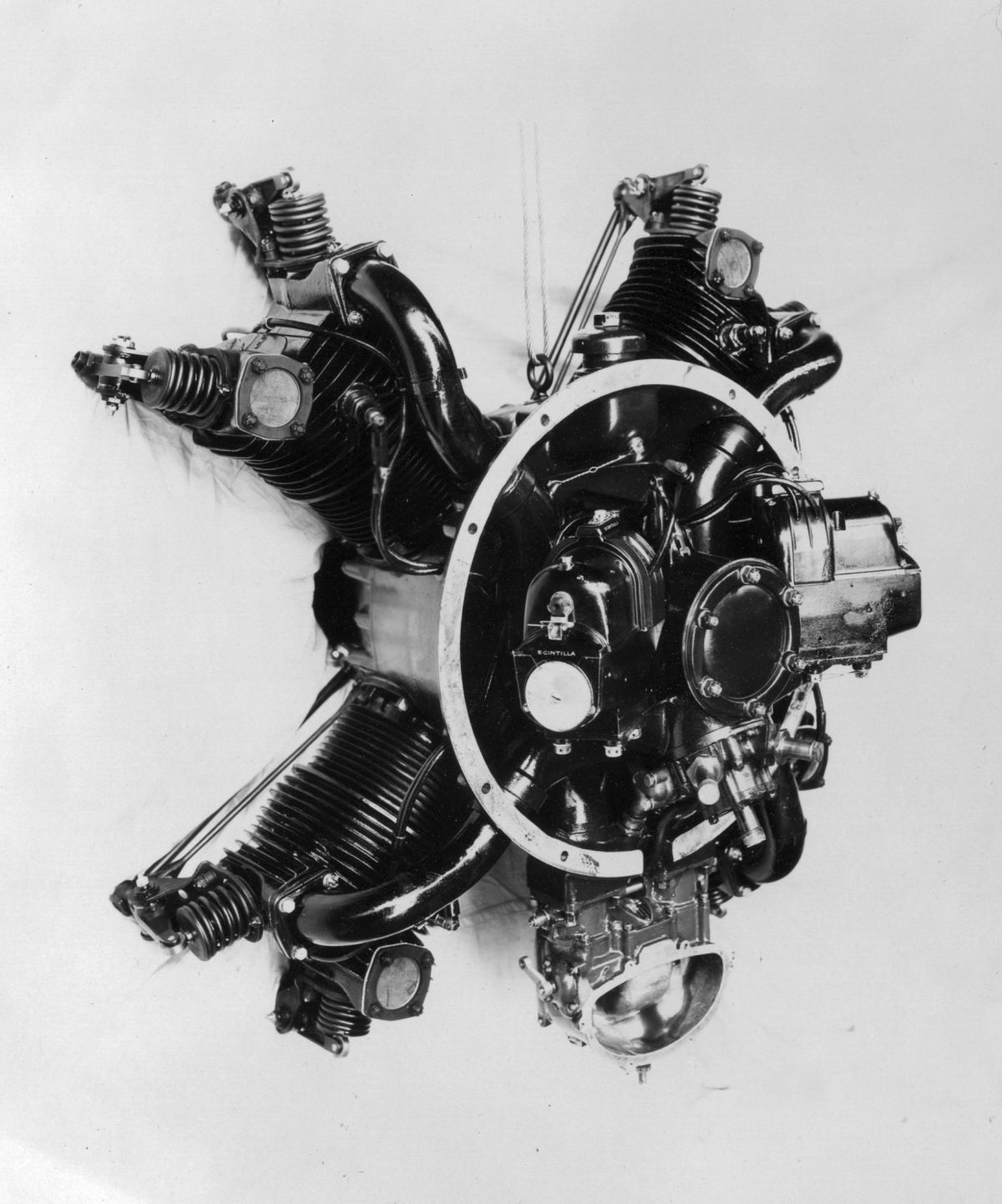
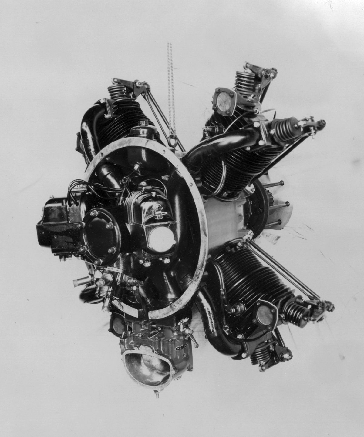
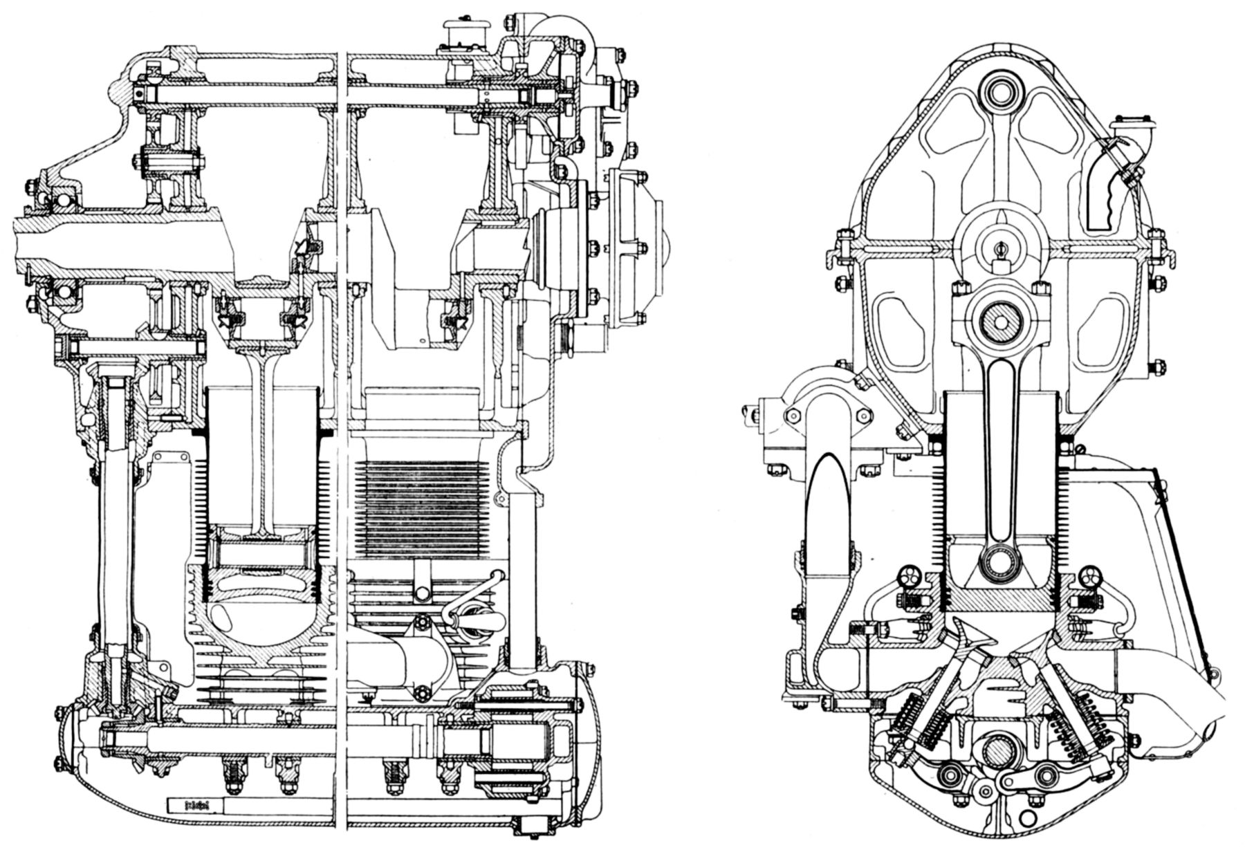
Since each piston made four strokes per revolution, the valve operating cams were mounted directly on the main shaft, eliminating the usual camshaft and driving gears. The main shaft was mounted on a front deep-groove ball bearing that carried both radial and thrust loads, a plain center bearing through which oil reached the main shaft, and a rear roller bearing. The split aluminum crankcase was joined in the cylinder plane. The front section supported the front and center main bearings, the valve cam followers, and the oil screen. The rear section supported the rear main bearing, and had an engine mounting flange. The carburetor, two magnetos, pressure and scavenging oil pumps, tachometer drive, and optional starter were attached to the rear section. The magnetos and oil pumps were driven by bevel pinions that meshed with a bevel gear on the accessory drive shaft end. The accessory drive gear was connected to the main shaft through a spiral slot and pin so that it would rotate with respect to the main shaft when moved fore or aft by means of a yoke and lever, thereby advancing or retarding the magneto timing. When an electric starter was employed, the starter dog engaged the accessory spline shaft so that magneto timing was automatically retarded. The cylinder barrels were made from steel forgings machined to include integral cooling fins and a mounting flange. The barrel was screwed and shrunk into an aluminum-alloy head with phosphor-bronze valve guides and shrunk-in valve seats. The valves, with 2.5"clear diameters and 0.5625" lift, were operated by push rods and rocker arms whose mounting brackets were tied at one end to the crankcase to compensate for expansion and maintain constant valve clearance. The four-ring aluminum slipper-type pistons had ribs under the heads for strength and cooling. The mixture was supplied by a Stromberg NA-U-5 duplex carburetor mounted on the rear section of the crankcase, being just below the oil sump through which the inlet pipes passed. Each opposite cylinder pair was connected to the same venturi for the purpose of obtaining the maximum induction charge ramming effect. Spur-gears pressure and scavenging oil pumps were contained in a single unit with the pressure pump drawing oil from a tank and delivering it to a front crankcase section compartment containing the oil screen. Pressurized oil passed into the engine shaft from which it was distributed throughout the engine.
The Fairchild-Caminez Model 447-B, with a 5.625" bore, 4.500" stroke and 447.3 in³ displacement, 5.2:1 compression ratio, and 114 psi bmep, was rated 135 hp at 1,050 rpm produced 142 hp at 1,120 rpm, and weighed 348 lb. Fuel consumption was 0.48 lb/hp/hr at cruise and 0.53 lb/hp/hr at full throttle. Oil consumption was 0.03 lb/hp/hr. Outside diameter was 37.56" and the overall length, minus starter, was 34.25".
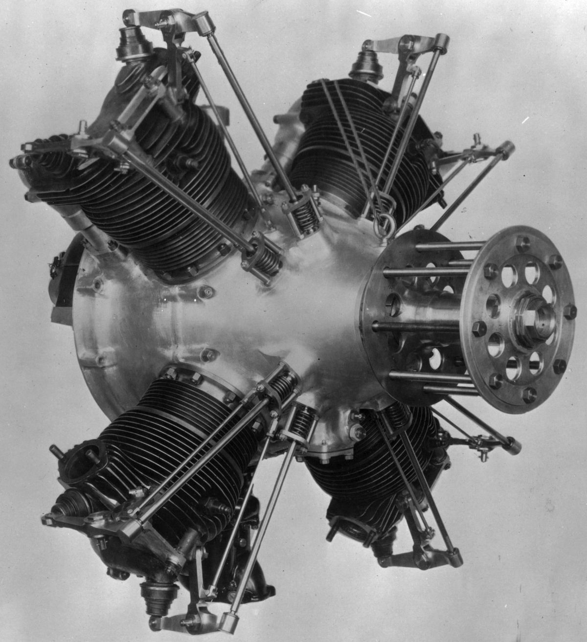
The Model 447-C. rated 120 hp at 960 rpm, received Department of Commerce Approved Type Certificate No. 1 on 1 June 1928, but by Fall 1928, Fairchild abandoned further development or manufacture. This decision came as a result of torque roughness during starting and stopping, and high piston side thrust. An eight-cylinder cam-type engine was built and tested, both on the block and in the air, and while torque roughness was greatly diminished, the high piston side thrust remained a serious problem.
 |
 |
 |
 |
 |
 |
| Right, Left Fore (NARA) | Left, Right Aft (NARA) | Top, Bottom (NARA) | |||
 |
| Fairchild 6-370 (A39) |
Shortly after dropping the Model 447, a new company, the Fairchild Engine Corporation, was formed and became a division of the Aviation Corporation.
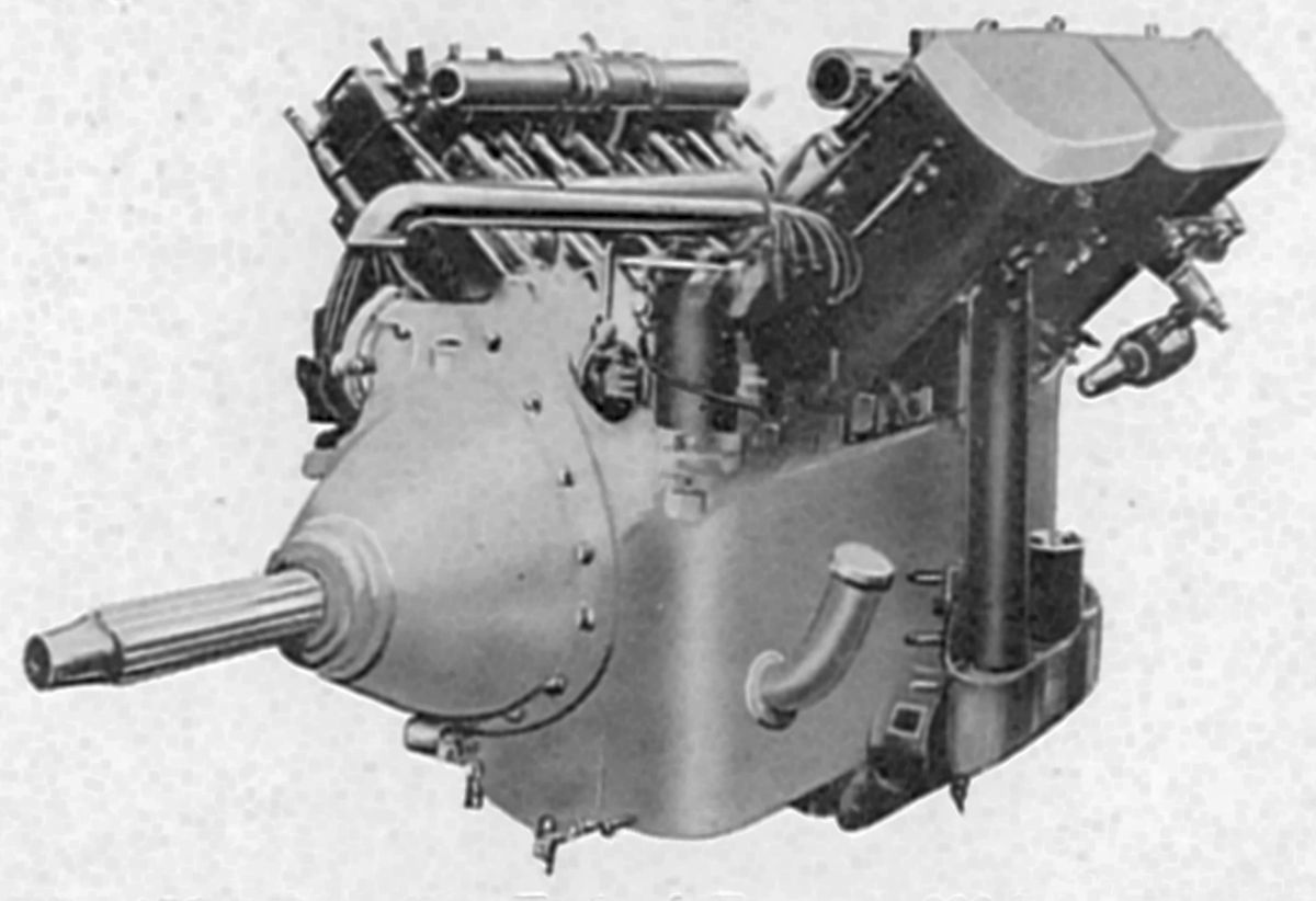
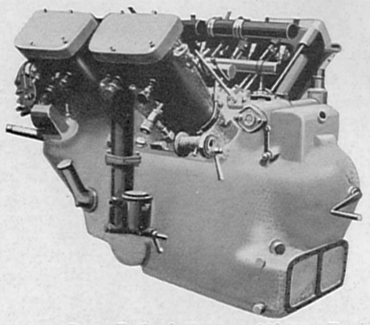
The Fairchild 6-370, an air-cooled inverted inline six, started production in May 1929. With a 3.9375" bore, 5.125" stroke, 274.4 in³ displacement, 5.1:1 compression ratio and 116.2 psi bmep, it was rated 110 hp at 2,000 rpm but produced 122 hp at 2,100 rpm. Its fuel consumption was 0.56 lb/hp/hr and its oil consumption 0.008 lb/hp/hr. Dry weight, without exhaust stacks or propeller hub, was 325 lb, or 2.95 lb per hp. Steel cylinder barrels with integral cooling fins were screwed and shrunk into aluminum-alloy heads with horizontal cooling fins. Eight studs held each cylinder assembly to the crankcase.
Bronze valve seats, guides, and spark plug bushings were shrunk into the cylinder heads. The valves, inclined to the cylinder axis at a 60° angle, were operated by rocker arms with rollers contacting the cams and flattened balls on the adjustment screws. The camshaft and rocker arms were supported in a housing bolted to the cylinder heads, with the inverted housing cover serving as an oil sump. The camshaft was driven by a vertical shaft and bevel gears at the engine front. The bevel gears were driven from a spur gear. idler that engaged with a crankshaft gear. The crankshaft was a conventional six-throw seven-main-bearing type. Starter jaws were machined at the rear end and the crankpin lightening holes were closed with easily removable plugs functioning as centrifugal oil cleaners. The H section connecting rods had white-metal-lined bronze shells at the big ends and bronze bushings at the piston ends. The aluminum crankcase was of an oval section, the two halves being joined along the horizontal crankshaft center line. Two long studs at each of the seven main bearing saddles extended through the lower crankcase section. The upper section carried two Scintilla magnetos that furnished dual ignition. A shallow section closing the crankcase rear end served as a mount for the pressure oil pump, oil screen, fuel pump, tachometer drive, generator and starter. The induction system consisted of two three-port manifolds downward fed through two steel tube elbows that connected with a T casting above the carburetor. The T casting was jacketed and fed with exhaust gas to serve as a hot spot. A single Stromberg carburetor furnished the mixture.
The Fairchild 6-390 engine (later known as the Ranger 6-390) was similar to the Model 6-370 except that the cylinder bore was increased to 4.000", which with a 5.125" stroke, gave a 386.4 in³. This engine was rated 120 hp at 2,150 rpm and was issued Department of Commerce Approved Type Certificate No. 57 on 14 Jul 1930. Its compression ratio was 5.2:1, bmep was 117.1 psi, fuel consumption was 0.55 lb/hp/hr and oil consumption was 0.025 l/hp/hr. Dry weight (minus starter, fuel pump and propeller hub) was 315 lb, or 2.88 lb/hp. The length (without starter) was 50.9", width was 18.063", and height was 31.09".
The Fairchild V-770, an air-cooled 60° V-12, used parts common to the 6-390. During early 1931, the American Airplane and Engine Corporation, an Aviation Corporation manufacturing division, was formed to take over Fairchild Airplane Manufacturing Corporation and Fairchild Engine Corporation manufacturing. The Fairchild 6-390 and V-770 became the Ranger 6-390 and V-770.
Farcot
Farcot Motors of Paris, France built air-cooled aircraft engines in several configurations. The smallest was a V-2 with cylinders offset from the crankshaft axis that developed 8 – 10 hp and weighed 55 lb. A combined inlet and exhaust valve, also used on other Farcot models, was operated directly from underneath by a three-step cam.
A six-cylinder fan engine used cast-iron cylinders with integral cooling fins. The cylinders were arranged in groups of three, which were staggered due to the two-throw crankshaft.
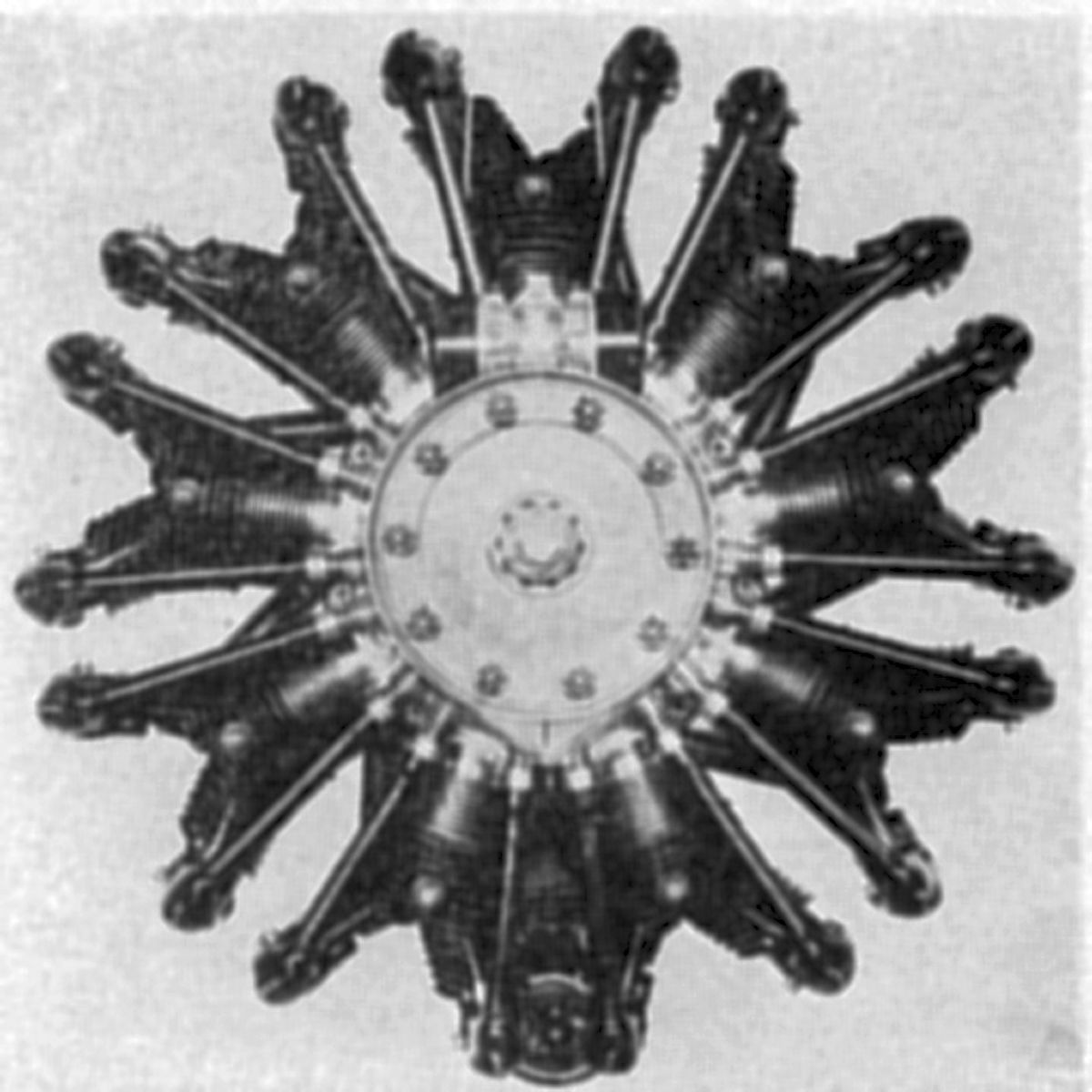
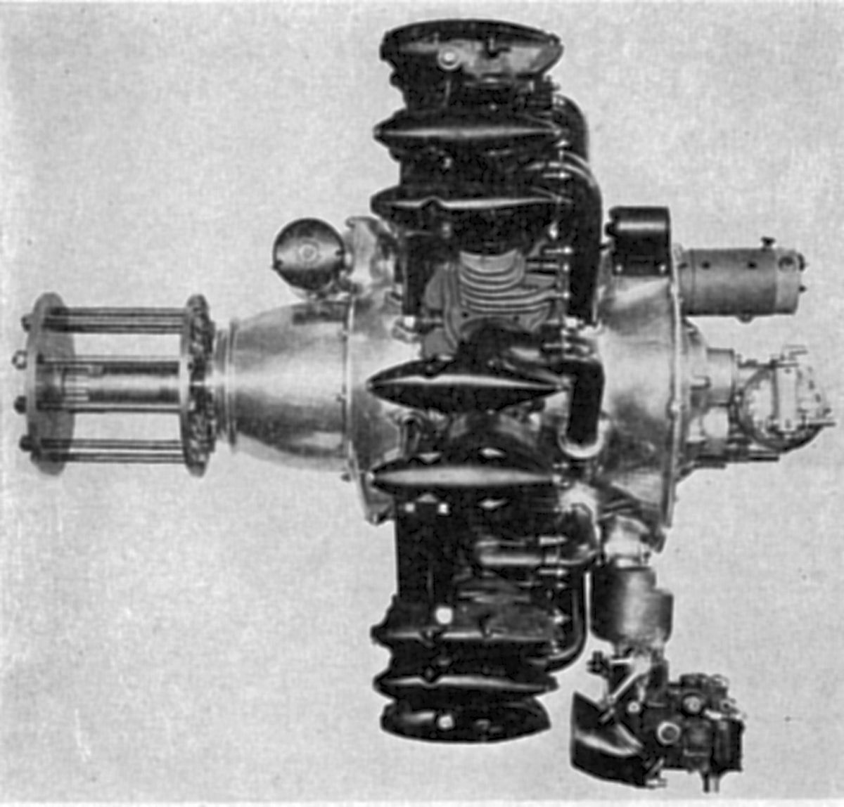
Radial eight-cylinder horizontal engines were built in 30, 50 and 100-hp versions. The 50-hp engine had a 105 mm (4.134") bore, 120 mm (4.724") stroke, 8.313 l (507.3 in³) displacement and delivered 64 hp at 1,200 rpm, 70 hp for short periods. The crankshaft, which had two throws 180° apart, drove the propeller shaft through bevel gears. A seven-bladed horizontally-mounted fan circulated air over the cylinders. Concentric valves, a gear oil pump, and two high-tension magnetos were used. Dry weight was 242 lb, or 3.7 lb/hp.
An air-cooled V-8 rated at 100 – 110 hp, was similar to Renault designs. Exhaust valves were arranged on top and connected by an exhaust manifold. A single carburetor was situated at one end of the engine. A fan on the propeller end drew air around the cylinders through a casing that enclosed them. This engine was provided with a compressed-air starter. A rather unique piston design used threaded fastenings instead of conventional piston pin bosses to adjust the compression ratio.
Farcot also built an air-cooled two-cylinder two-stroke rotary engine that employed crankcase compression.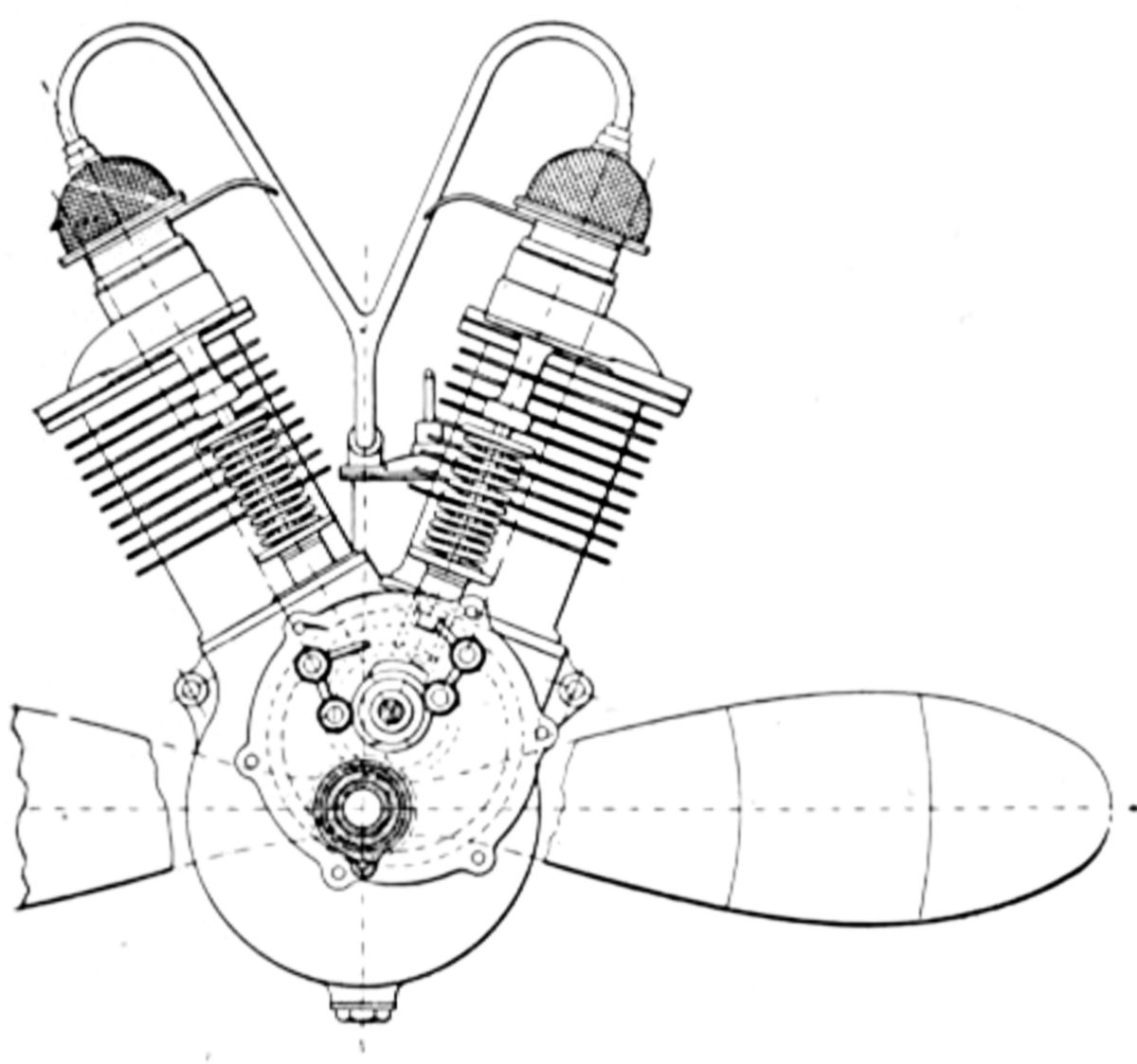 |
 |
 |
 |
| V-2 | Fan-6 | V-8 | |
Farina
The Stabilimenti Farina automobile firm in Turin, Italy began building aircraft engines during 1928. The two original air-cooled seven-cylinder radials were available either as direct-drive or geared engines, but were otherwise identical. With 87 mm (3.425") bores, 110 mm (4.331") stokes, 4.577 l (279.3 in³) displacements, 30" diameter and 5.5:1 compression ratios, their fuel consumption was 0.508 lb/hp/hr and oil consumption was 0.022 lb/hp/hr. The cylinders were one-piece iron castings with integral cooling fins. Single inlet and exhaust valves, inclined at 52° to the cylinder axis, were operated by push rods and enclosed rocker arms. The two-section crankshaft had integral counterweights and the sections were joined at the crankpin by a straight cylindrical spigot and two taper alignment pins. Slipper type connecting rods with diagonally-cut ends bore on a floating bronze bushing with internal rollers; hardened steel rings retained the assembly. A dry-sump lubrication system was used. Recesses in the barrel crankcase streamlined nose accommodated two Marelli magnetos that furnished dual ignition. The mixture, provided by a duplex Zenith 36 DC carburetor, entered two spiral passages shaped to give constant gas velocity and a rotary motion that insured uniform distribution.
 |
 |
 |
| Algol (A39) | T.58 (A39) | |
The direct-drive Alioth was rated 68 hp at 1,750 rpm, but could produce 75 hp at 1,950 rpm; it weighed 242 lb.
The geared Algol was rated 92 hp at 2,400 rpm but could produce 100 hp at 2,800 rpm. Weight was 253 lb. The integral reduction gear used the front crank web as part of the epicyclic gear; planet pinions were mounted on a shaft carried in the hollow crankpin. These pinions meshed with two internally-toothed rings, the rear one fastened to the crankcase and the front one to the propeller shaft.
Farina introduced the T.58, an air-cooled five-cylinder radial in early 1932. With a 120 mm (4.724") bore, 142 mm (5.591") stroke and 8.030 l (490.0 in³) displacement, it was rated 135 hp at 1,850 rpm and could deliver 142 hp at 1,950 rpm. With a 5.4:1 compression ratio the T.58 developed a 142 psi bmep, weighed 317 lb, or 2.4 lb/hp, had a 41.37" diameter and was 32.39" long. Fuel consumption was 0.46 lb/hp/hr.
Several original design features were retained, including the slipper-type connecting rods bearing on a floating bushing carried on roller bearings. The crankshaft was made in three sections, each with integral counterweights. Cylinder design was changed to steel barrels with cast-iron heads. Although the new valve arrangement was similar to the old, the cam ring, push rods and push rod tubes were moved to the aft engine side. The cams contacted rollers at the ends of pivoted levers that actuated push rods guided in the crankcase, thereby relieving push rod side loads. The magnetos were also mounted aft, with the crankcase front only carrying the crankshaft roller journal bearing and radial ball propeller thrust bearing. The two crankcase halves were joined in the cylinder plane by five long studs that were also used for mounting the engine. Ribs under the piston heads improved piston cooling.
Farman
The French aircraft manufacturer Socété des Avions H. M. et D. Farman, with factories at Billancourt (Seine), began aircraft engine design and manufacture aimed at civil aviation shortly after WWI.
 |
 |
| Farman 200 hp V-8 (AEE) | |
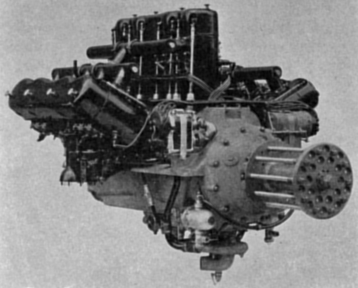
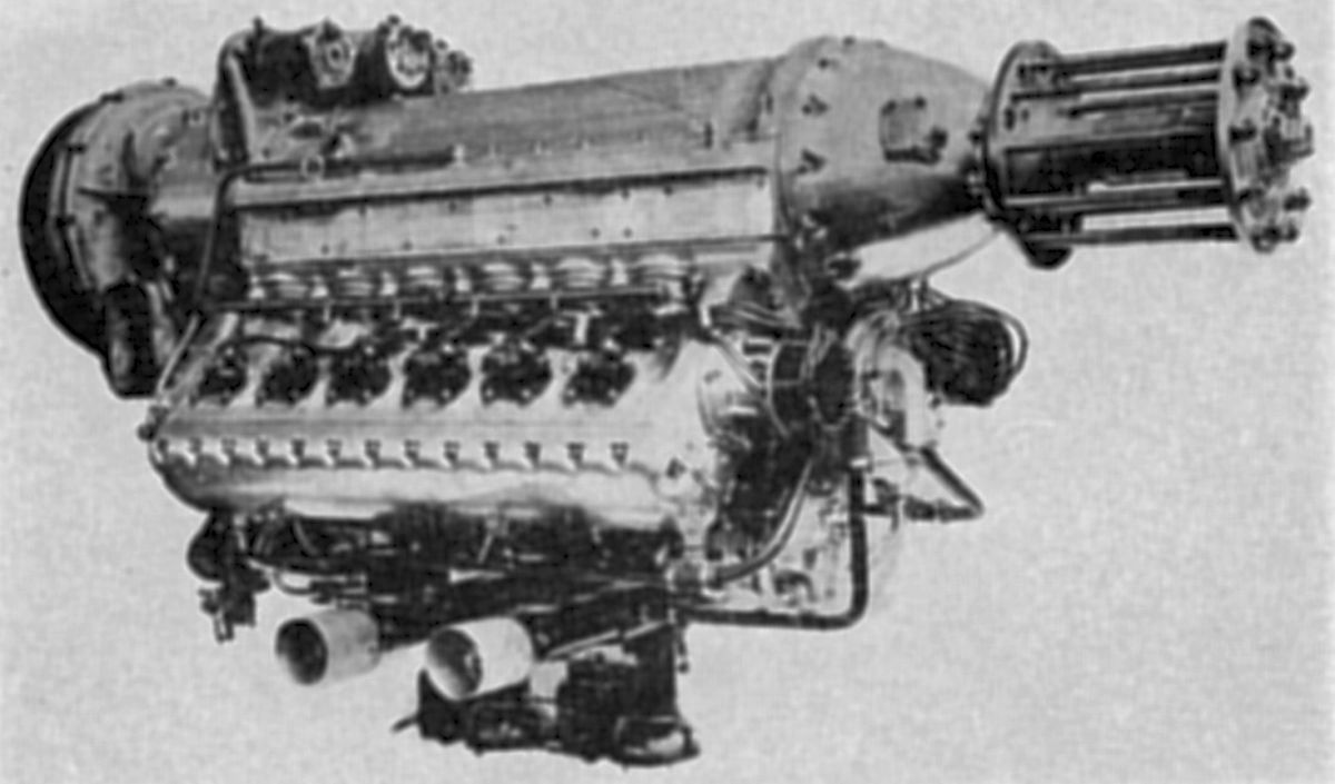
The first Farman engine was a water-cooled V-8 rated at 200 hp. It weighed 700 lb, or 3.5 lb/hp. The built-up, welded-steel cylinders were made in pairs. Push rods and rockers operated the valves, were enclosed by aluminum covers and fed directly with oil. The oil supply was carried in the crankcase base chamber. Magnetos provided dual ignition and a Ragonet electric starter and an impulse magneto were fitted. The propeller was driven through bevel planetary gears of the well-known Farman design, which included one fixed crown bevel, a differential spider with four satellites, and a crown bevel wheel. A water-cooled V-12 of similar design was rated at 400 hp. This engine soon was supplanted by a water-cooled W-12 with a 130 mm (5.118") bore, 160 mm (6.299") stroke, 28.485 l (1,555.2 in³) displacement and 5.5:1 compression ratio was rated 400 hp at 1,880 rpm and weighed 1,100 lb. Fuel consumption was 0.484 lb/hp/hr and oil consumption was 0.022 lb/hp/hr.
 |
 |
| Farman 12WE, with Supercharge (A39) | |
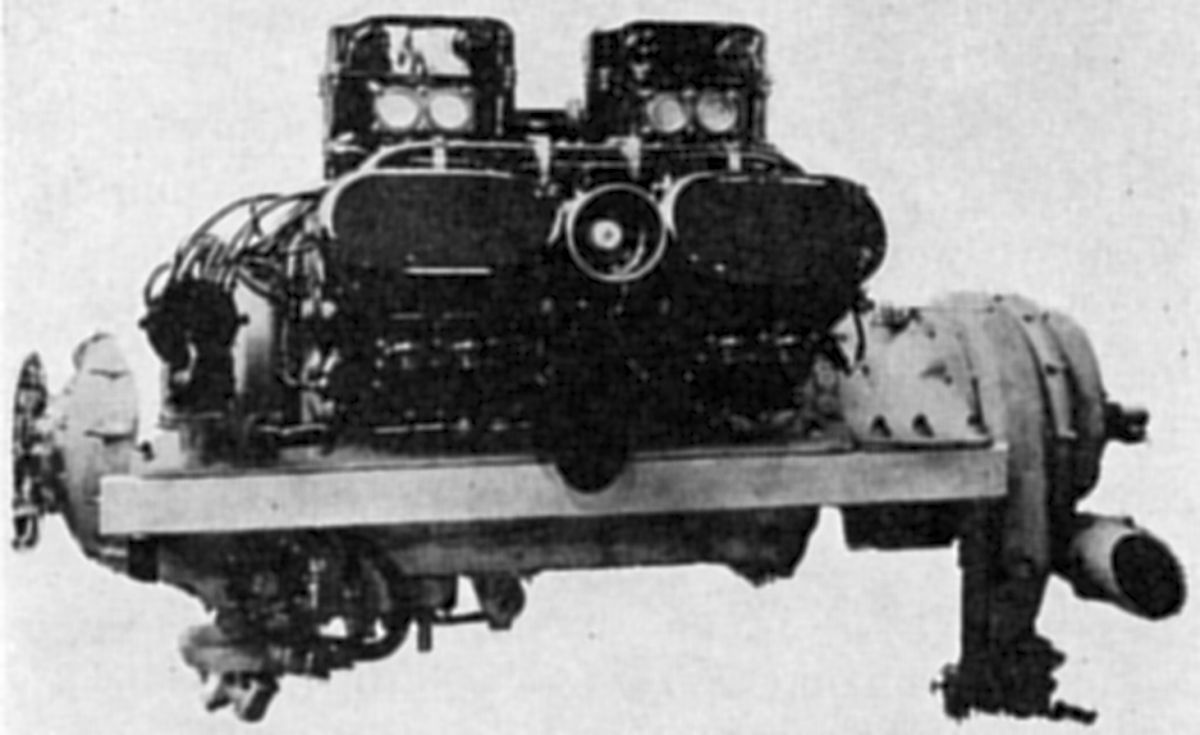
The 12WE, a more refined water-cooled W-12 with the same bore, stroke and displacement was introduced in 1924. With a 5.3:1 compression ratio, it was rated 500 hp at 2,150 rpm and could produce 550 hp at 2,200 rpm. The direct-drive engine weighed 1,034 lb; with Farman propeller reduction gears, the engine weighed 1,122 lb. Steel cylinders with a common welded-on sheet-metal water jacket were arranged in pairs. The overhead valves were operated by push rods from camshafts located at each Vee's center and driven through a gear train from the crankshaft propeller end. Pistons and crankcase were aluminum-alloy castings. The crankshaft was supported on white-metal-lined plain bearings. A disc with driving dogs at the crankshaft front accommodated either a bolted-on propeller shaft or reduction gear drive. The crankshaft gear driving the cam gear train also meshed with a pinion at the crankcase bottom that drove oil, water, and fuel pumps. A front-mounted cross shaft driven from a camshaft drove two magnetos or two distributors. The dry-sump lubrication system used gear-type pumps to draw oil from both crankcase ends and force it through cooler, from which it was flowed to all bearings through a filter that could be bypassed and withdrawn for cleaning while the engine was running. Cooling water was circulated by a centrifugal pump fitted with a throttling device to regulate the water flow rate and thereby maintain correct water temperature. The carburetors were situated outside the outer cylinder rows and the induction pipes had water jackets. Some 12WE engines were fitted with centrifugal superchargers. Propeller reduction gears were available with 2:1 and 1.35:1 ratios.
 |
| 600 hp W-18 (AEE) |
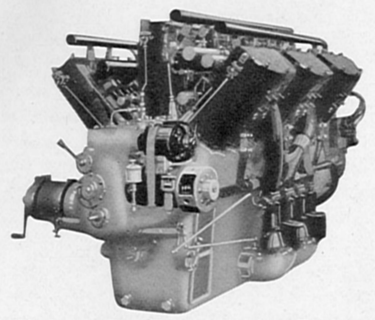
A W-18 engine using similar construction to the 12WE was next introduced. With a 130 mm (5.118") bore, 180 mm (7.087") stroke, 43.005 l (2,624.3 in³) displacement it was rated 600 hp at 1,860 rpm and weighed 1,848 lb. As with the 12WE the cylinders, built up in pairs, each had four interchangeable overhead valves operated by rocker arms and push rods from camshafts in the Vees. Articulated connecting rods were used and the link rods had tubular shanks. These engines were either direct-drive or used Farman bevel-planetary reduction gears with standard 2:1, 1.83:1, 1.67:1 and 1.5:1 ratios. Six carburetors, three on each side, fed three cylinders each.
The 18WD, a more refined version of the earlier W-18, was rated 700 hp at 1,850 rpm and produced 820 hp at 2,100 rpm. It weighed 1,716 lb and consumed 0.495 lb/hp/hr. It was equipped with magneto and battery ignition.
 |
 |
| Farman 18WI W-18, with Supercharger (A39) | |
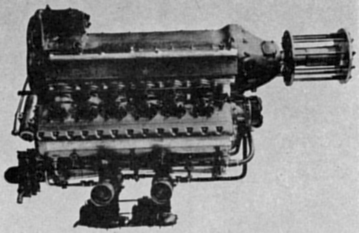
The 18WI, introduced in 1926, had a different construction than former Framan water-cooled W-18s. It was also adaptable to inverted installation. Its bore was 110 mm (4.331"), its stroke 125 mm (4.921"), its displacement 21.382 l (1,304.8 in³) and its compression 5.7:1. It was rated 550 hp at 2,600 rpm but could produce 730 hp at 3,400 rpm. Its bare weight was 701 lb, but with a 2.46:1 propeller reduction gear, starter and propeller hub it weighed 930 lb. It was 67.69" long without supercharger, 80.29" long with supercharger, 30.7" wide and 42.67" high. Each six-cylinder row, including cylinder heads and valve ports, was cast en-bloc of Alpax, a ductile silicon-aluminum alloy. Steel liners were pressed into these castings from inside. The three blocks were mounted on an aluminum crankcase at a 40° included angle. The valves seated upon inserts and were operated via rocker arms and overhead camshafts enclosed in aluminum housings that were bolted to the cylinder blocks. The crankcase was divided horizontally along the crankshaft centerline and was closed at the front by the reduction gear casing. The six-throw, seven-main-bearing crankshaft used articulated rods with H-section link rod shanks. Light alloy cast aluminum pistons were fitted with full-floating pins. Spur gear trains at the engine front drove the camshafts. Intermediate gears in the outer block camshaft gear trains drove two 18-cylinder ignition distributors and a water pump on the center block. The dry-sump lubrication system furnished pressurized oil to all bearings. Two Zenith carburetors were suspended below the cylinders; one fed the aft nine cylinders and the other the nine forward cylinders. When fitted with a Rateau supercharger, the engine could maintain 600 hp up to 5,684 m (18,000 ft).
The 12WI was a water-cooled 60° V-12 with a 2:1 reduction gear ratio. With a 135 mm (5.315") bore, 140 mm (5.512") stroke, 24.047 l (1,467.4 in³) displacement and 5.5:1 (later 5.9:1) compression ratio, it was rated 540 hp at 2,260 rpm and could produce 603 hp at 2,700 rpm. It was 59.1" long, 43.34" wide and 35.46" high. Cylinder construction was similar to the 18WI. A Zenith carburetor supplied the mixture, and Ducellier magnetos the ignition. Bare dry weight was 902 lb, and complete weight was 1010 lb. Fuel consumption was 0.539 lb/hp/hr and oil consumption was 0.026 lb/hp/hr. A Farman two-stage supercharger maintained rated output up to 2,000 m (6,562 ft) with the first stage, and up to 5,100 m (16,732 ft) with the second stage.
The 8VI, a water-cooled 90° V-8 and companion of the 12WI displacing 16.032 l (978.3 in³), was rated 350 hp at 2,500 rpm and delivered 418 hp at 2,700 rpm. It weighed 704 lb, was 57.13" long, 37.43" wide and 32.5" high.
 |
 |
| Farman 9Ea (A39) | |
The 9Ea was an air-cooled nine-cylinder radial with a 2:1 Farman reduction gear, 115 mm (4.528") bore, 120 mm (4.724") stroke, 11.218 l (684.6 in³) displacement and 5.75:1 compression ratio that was rated 250 hp at 2,600 rpm and capable of 280 hp at 2,700 rpm. Dry weight was 583 lb, or 2.33 lb/hp. Fuel consumption was 0.5 lb/hp/hr and oil consumption was 0.033 lb/hp/hr. Outside diameter was 42" and length was 46". The 9Ea cylinders used steel barrels with integrally turned cooling fins that were screwed into cast aluminum alloy heads. Two inclined valves were operated by fully enclosed push rods and rocker arms driven by a cam ring at the engine front. A full-floating piston pin, two compression rings and two scraper rings were fitted to each aluminum piston. The two-piece forged steel crankshaft included a crankpin integral with the front section. The master connecting rod big end was fitted a floating bushing. The four-section crankcase inner sections were joined in the cylinder plane. The forward inner section housed the timing gears and distributors, and the rear section contained a mixture distribution fan driven at four times crankshaft speed. The nose section enclosed the propeller reduction gears, and the rear cover supported the oil pumps, generator and starter. The mixture was supplied by a Claudel carburetor, and the ignition by battery and coil. Lubrication was a force-fed dry-sump type using gear pumps; oil was scavenged from both crankcase ends.
The 9Eb, introduced in 1929, had a 115 mm (4.528") bore, 135 mm (5.315") stroke, 12.62 l (770.1 in³) displacement and 5.4:1 compression ratio. It was rated 250 hp at 2,150 rpm and 270 hp at 2,200 rpm. Dry weight was 550 lb. The mixture was furnished by a Stromberg carburetor, and dual ignition by Ducellier magnetos. Fuel consumption was 0.53 lb/hp/hr and oil consumption 0.0265 lb/hp/hr. The 9Eb diameter was 41.76" and its length was 47.28". Farman continued to improve the 9Eb and produced other 9E models through the 1930s.
Fox
 |
| Fox DeLuxe (AEE) |
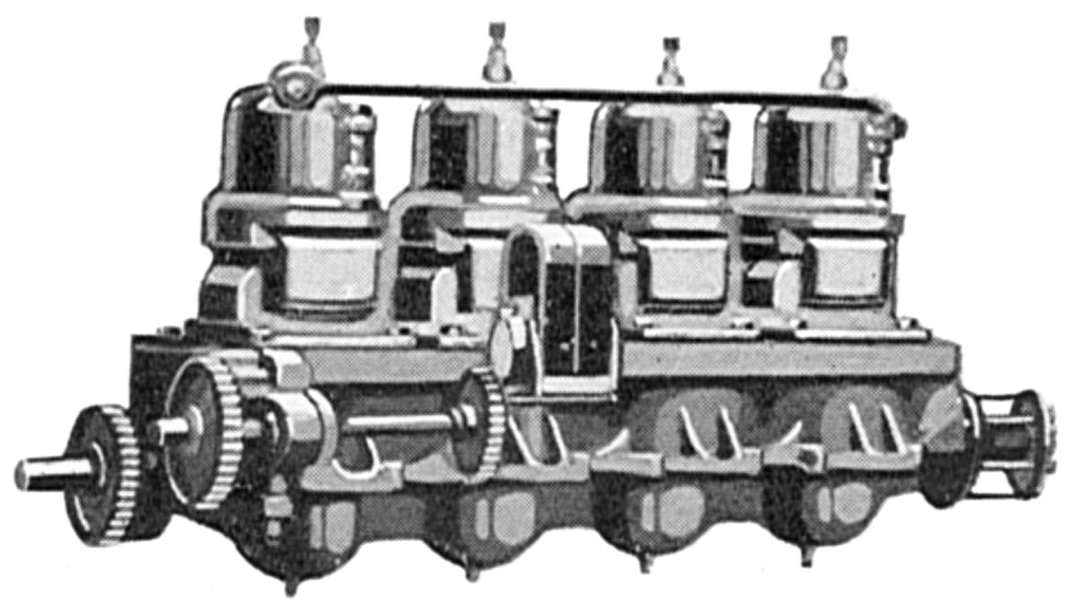
The Dean Manufacturing Company of Newport, Kentucky built Fox airplane engines during 1911 and 1912. These water-cooled vertical inline two-strokes used a special pilot-controlled fourth port, known as an accelerator. This port was located below the inlet port and admitted only air to scavenge burnt gases before the fuel charge entered the cylinder via the transfer port. When the accelerator was closed the engine operated as the usual three-port two-stroke.
A 36 hp four-cylinder with a 3.5" (88.9 mm) bore, 3.5" (88.9 mm) stroke and 134.7 in³ (2.207 l) displacement weighed 150 lb, or 4.15 lb/hp.
A 45-hp three-cylinder with a 4.0" (101.6 mm) bore, 4.0" (101.6 mm) stroke and 150.8 in³ (2.471 l) displacement weighed 150 lb, or 3.34 lb/hp.
A 60 hp at 1,000 rpm four-cylinder with a 4.0" (101.6 mm) bore, 4.0" (101.6 mm) stroke and 201.1 in³ (3.296 l) displacement weighed 190 lb, or 3.17 lb/hp.
A 90 hp at 1,000 rpm six-cylinder with a 4.0" (101.6 mm) bore, 4.0" (101.6 mm) stroke and 301.6 in³ (4.942 l) displacement weighed 280 lb, or 3.11 lb/hp.
The DeLuxe, a four-cylinder with a 4.75" (120.65 mm) bore, 4.25" (107.95 mm) stroke and 301.2 in³ (4.937 l) was rated 50 hp at 1,200 – 1,300 rpm.
The largest Fox engine had eight vertical cylinders, a 6.0" (152.4 mm) bore, 6.0" (152.4 mm) stroke, 1,357.2 in³ (22.240 l) displacement was rated 200 hp and weighed 850 lb, or 4.25 lb/hp.
References
Angle, Glenn D, ed. Aerosphere 1939 (New York, New York: Aircraft Publications, 1940).
Anble, Glenn D, ed. Airplane Engine Encyclopedia (Dayton, Ohio: Otterbein Press, 1921).
Image Sources: A39 = Aerosphere 1939; AEE = Airplane Engine Encyclopedia; Flt = Flight Magazine; NARA = U.S. National Archives and Records Administration; UKNA = United Kingdom National Archives.
Send mail to
![]() with questions or comments about this web site.
with questions or comments about this web site.
![]()