Selected Early Engines
Cirrus, Clerget, Cosmos, Curtiss
Compiled by Kimble D. McCutcheon
Published 6 Apr 2022; Revised 26 Apr 2022
Curtiss
Among the first successful aircraft engines marketed in America were those designed and built by Glenn H. Curtiss and his associates at Hammondsport, New York. During 1917 and 1918, the K-12 and K-6 engines were designed under the direction of Charles B. Kirkham, who had been associated with Glenn H. Curtiss for a number of years, and was at that time chief engineer. After Kirkham resigned, Finley R. Porter was appointed chief engineer and the C-6 and C-12 engines were built under his direction. Later, Arthur Nutt was appointed chief engineer, and all Curtiss engines after the D-12 were built under his supervision. During 1930, the Curtiss engine division moved to Paterson, New Jersey, and merged with the Wright Aeronautical Corporation as a part of the newly-formed Curtiss-Wright organization.
The C-1, an air-cooled single, was the first Curtiss engine. From a 3.2" bore and stroke, 26.5 in³ displacement and 40 lb weight, it produced 3 hp at 1,800 rpm. Its crankshaft ran on roller bearings, it employed battery ignition and used plash lubrication.
The A-2, an air-cooled two-cylinder with a 3.250" bore, 3.625" stroke and 60.1 in³ displacement, developed 7 hp at 1,500 rpm and weighed 50 lb Battery ignition and splash lubrication were used.
The A-4, an air-cooled four-cylinder with a 3.25" bore and stroke and 107.84 in³ displacement, was rated 15 hp at 1,800 rpm and weighed 90 lb A sight-feed oiler was used in connection with splash lubrication and battery ignition. The chrome-steel crankshaft was mounted in plain bearings of Parson's White Brass and McAdamite Metal. It was 20" long, 7" wide and 15"high.
The B-4 was similar to the A-4 but with 3.625" bore, 3.250" stroke and 134.2 in³ displacement, delivered 20 hp at 1,800 rpm and weighed 100 lb, or 5 lb/hp.
|
| Curtiss C-4 (AEE) |
The C-4, a larger air-cooled four-cylinder with a 3.625" bore, 4.000" stroke and 165.13 in³ displacement, was rated 25 hp at 1,800 rpm and weighed 110 lb A magneto furnished ignition. It was 20" long, 7" wide and 18" high.
The A-8, an air-cooled 90° V-8 with the same 3.25" bore and stroke as the A-4, displaced 215.7 in³ and produced 30 hp at 1,800 rpm from 140 lb, or 4.66 lb/hp.
The B-8, an air-cooled V-8 90° V-8 with the same 3.625" bore and 3.25" stroke as the B-4, displaced 268.3 in³ and produced 40 hp at 1,800 rpm from 150 lb, or 3.75 lb/hp. This was the first Curtiss engine to sustain a heavier-than-air machine in flight, and was also the first to lift a helicopter.
The E-4, a vertical four, was the first water-cooled Curtiss engine. With a 5.00" bore, a 5.00" stroke and 392.7 in³ displacement, it was rated 50 hp at 1,500 rpm. Dry weight was 250 lb, or 5 lb/hp. Its cast-iron cylinders were fitted with copper water jackets. The inlet valve was located on the side and the exhaust valve in the cylinder head. Battery ignition and a splash lubrication were employed. The U. S. Signal Corps Dirigible No. 1, purchased from Thomas S. Baldwin in 1908, was powered by a Curtiss engine delivering 20 hp at 450 rpm. Some believe this engine was an E-4 with reduced output due to low operational speed.
The E-8 was a 90° V-8 using E-4 cylinders and displacing 785.4 in³ was rated 100 hp at 1,500 rpm. It weighed 350 lb, or 3.5 lb/hp.
 |
| Models H, K (AEE) |
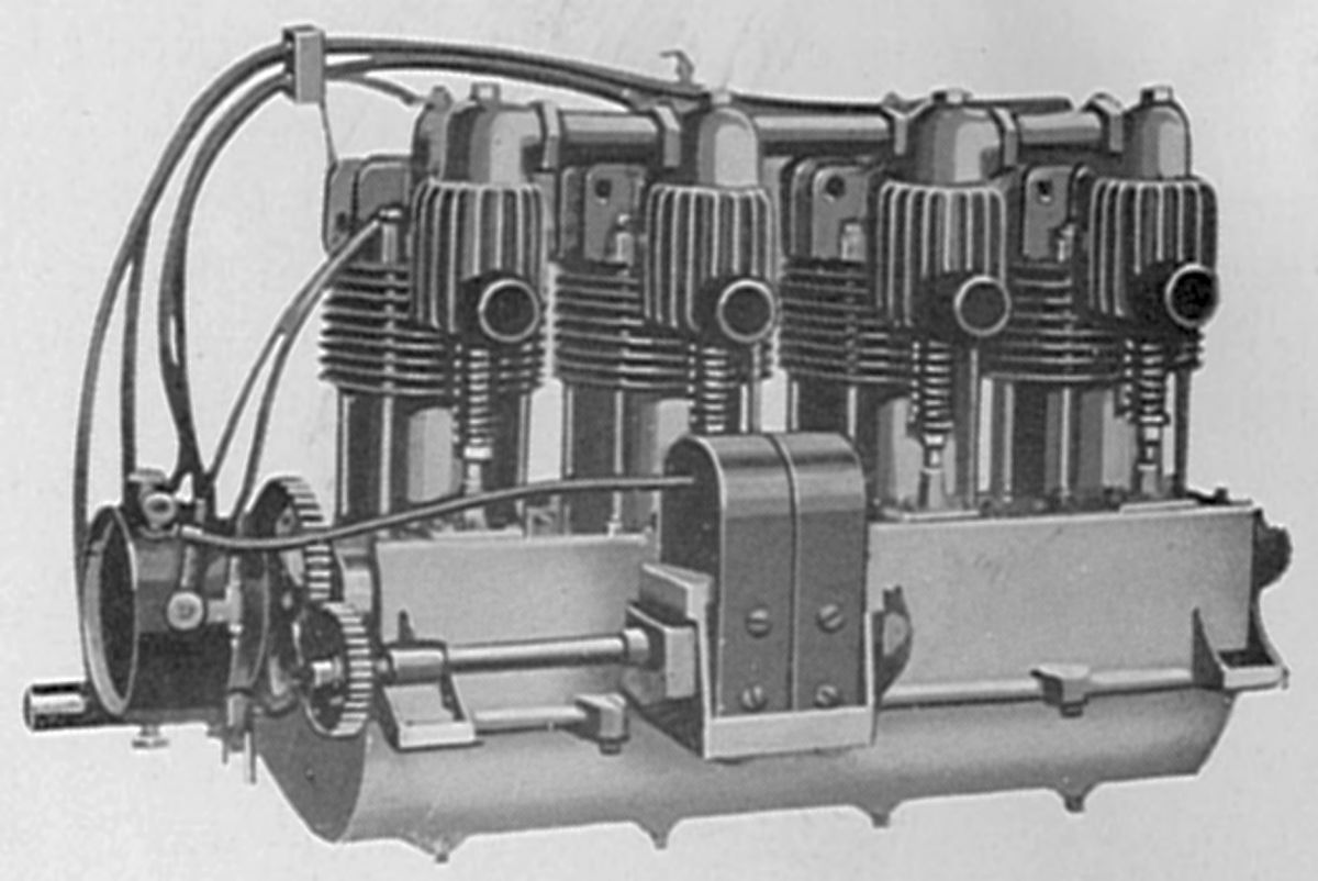
The Model H and Model K were four-cylinder vertical water-cooled engines with 4.000" bores, 5.000" strokes and 251.3 in³ displacements rated 40 hp at 1500 rpm. These engines weighed 175 lb, or 4.38 lb/hp They were 20" long, 12" wide and 30.5" high. A single Schebler carburetor furnished the mixture, and a Bosch magneto the ignition. A combination splash and pressure lubrication system used gear type pumps. The cast-iron cylinders had brazed-in-place sheet-metal water jackets. The inlet and exhaust valves, both inclined in the cylinder head, were each operated by a single push rod and rocker arm.
 |
| Models S (AEE) |
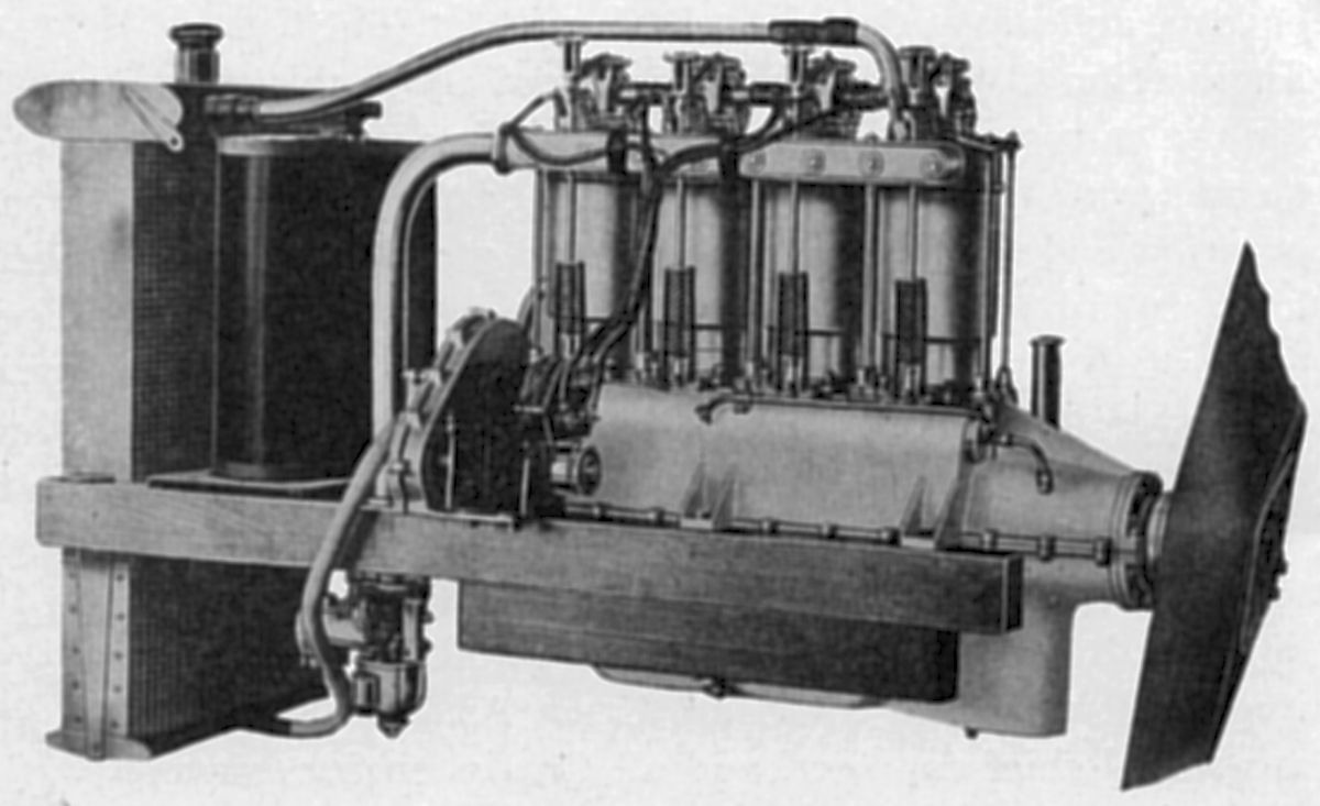
The Model S, a water-cooled vertical six with the same 4.000" bore and 5.000" stroke as the H and K models, displaced 377.0 ³ and was rated 60 hp at 1,600 rpm and 70 hp at 1,325 rpm. Weight was 245 lb, or 4.08 lb/hp. It was 31.125" long, 12" wide and 30.5" high.
The Model L was a water-cooled V-8 with construction similar to the Model S using the same 4.000" bore and 5.000" stroke, displaced 502.7 in³, produced 80 hp at 1,500 rpm and weighed 285 lb, or 3.56 lb/hp. Its length was 50", its width 30" and its height 27".
The Model O was an improved Model L rated 75 hp at 1,100 rpm.
The Model OX was a further refinement of the Model O rated 90 hp at 1,200 rpm. Several types, such as the OX-2 and OX-5, facilitated special installations with the addition of various equipment. The Curtiss Models OX and OXX the most prolific of American WWI engines. First available in 1915, the OX-5 was installed in the Curtiss JN-4, the standard for training in the U.S.A. and Canada during WWI. Production continued by Curtiss and other licensees until 1919. War-surplus OX-5s powered a veritable explosion in general aviation after WWI and for a decade to follow. In 1929, 2,510 of 6,631 licensed airplanes (38%) were powered by OX-5s. In the eleven months ending March 1, 1930, 4,574 planes were licensed. Of these, 1,359 were powered by war-surplus OX-5s and only 1,016 by brand-new state-of-the-art Wright Whirlwinds. Though almost all new aircraft engines were better, few could compete with the low cost of war-surplus engines (some sold new in the crate for a mere $20.00). The year 1929 was the first year that the total number of NEW airplane designs using non-OX-5 power exceeded those using the OX-5!
OX-5 cylinders were individually cast from grey iron and had monel jackets brazed in place. Single inlet and single exhaust valves seating directly on the cast-iron cylinder head were inclined from the cylinder axis and actuated by push-pull rods and rocker arms. Eight double-acting cams on a single camshaft were located in the Vee and retained in split aluminum camshaft bearings. The four-throw, five-main-bearing crankshaft had side-by-side H-section connecting rods on each crankpin. The cast aluminum alloy pistons were fitted with two rings. A single eight-cylinder magneto furnished ignition and a Zenith duplex carburetor furnished the mixture. A gear-type pump maintained oil pressure by forcing oil from the oil sump to hollow camshaft aft end from where it flowed to the timing gears and all bearings. Fuel consumption was 0.60 lb/hp/hr and oil consumption 0.03 lb/hp/hr. Dry weight was 390 lb, or 4.33 lb/hp. The OX-5 was 56.75" long, 29.75" wide and 36.75" high.
 |
 |
 |
 |
 |
| Curtiss OX-5 (NARA, AEE) | ||||
The Model OXX was practically identical to the OX except for a larger bore. With a 4.25" bore, 5.00" stroke and 567.4 in³ displacement, it produced 100 hp at 1,400 rpm from a 401 lb dry weight.
The V was a water-cooled V-8 with a 5.00" bore, 7.00" stroke, 1,099.6 in³ displacement producing 160 hp at 1,100 rpm.
The VX, nearly identical to the V, was rated 180 hp at 1,400 rpm.
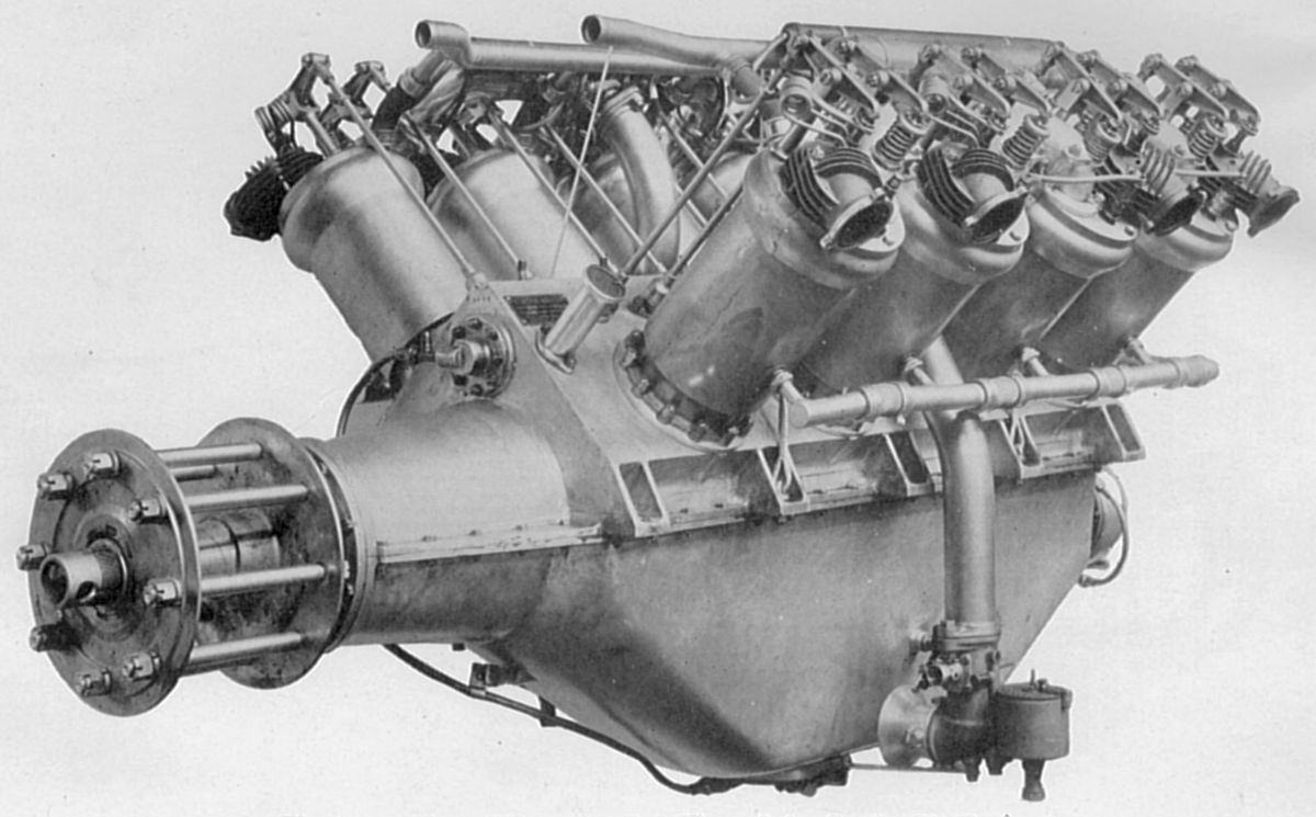
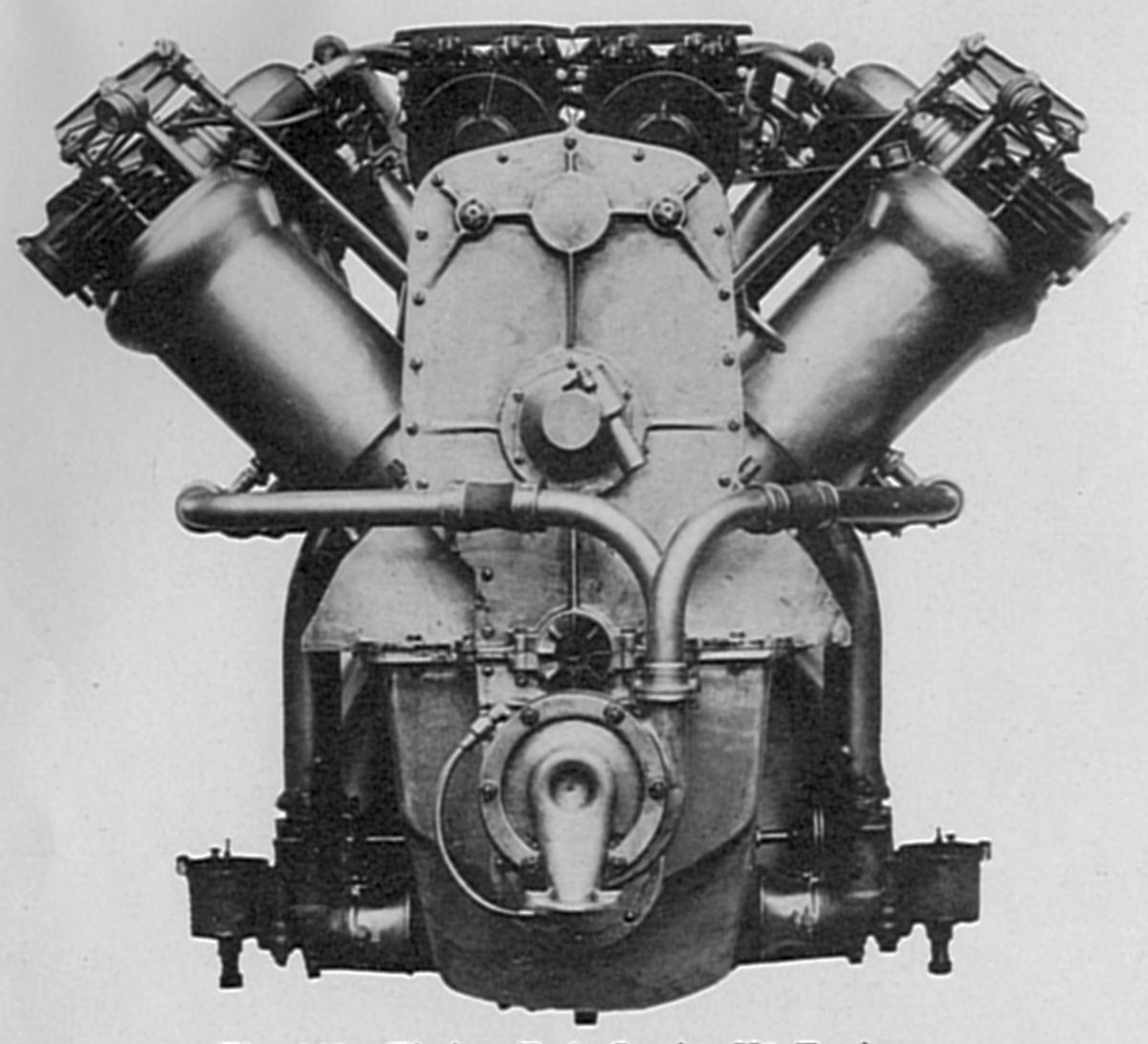
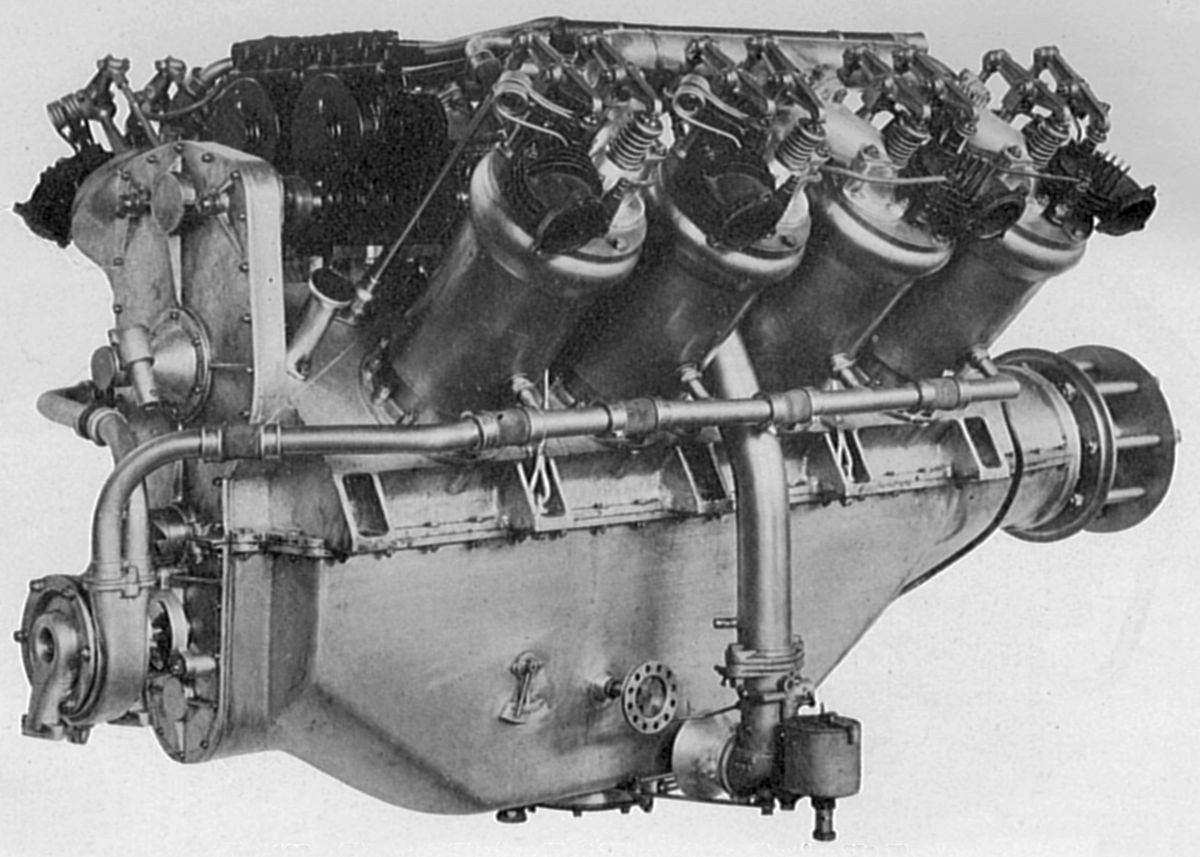
The V2, a more refined water-cooled V-8 with a 5.00" bore, 7.00" stroke and 1,099.6 in³ displacement, was rated 200 hp at 1,400 rpm. Its staggered individual forged-steel cylinders were machined all over and fitted with welded-in-place monel sheet water jackets. Single 2.5" clear-diameter inlet and exhaust valves seated directly on the flat cylinder head. The inlet valve used a coil spring while the exhaust valve used a hairpin spring. Each valve was operated by a separate push rod and rocker arm from a camshaft mounted in the Vee. The four-throw crankshaft ran in five plain bearings. Side-by-side H-section connecting rods used a tube to deliver oil to the piston-pin bearing. The aluminum pistons were ribbed inside and fitted with two rings. Dual ignition was supplied by two eight-cylinder magnetos, and two Zenith carburetors, located on either side of the engine, each fed four cylinders. Oil was pumped from the sump to the bearings at about 60 psi by a gear pump. Fuel consumption was 0.54 lb/hp/hr while oil consumption was 0.03 lb/hp/hr. Dry weight was 690 lb, or 3.45 lb/hp. The V2 was 68" long, 37" wide and 34" high.
 |
 |
 |
 |
 |
 |
| Curtiss V2 (AEE) | |||||
The V-4, a water-cooled V-12 using V2 cylinders and displacing 1,649.3 in³, was rated 300 hp at 1,400 rpm and 350 hp at 1,600 rpm. It weighed 1,086 lb. A hydroplane boat powered by a V-4 engine for a time held the world's speed record of 66 mph.
 |
| Curtiss V-3 (AEE) |
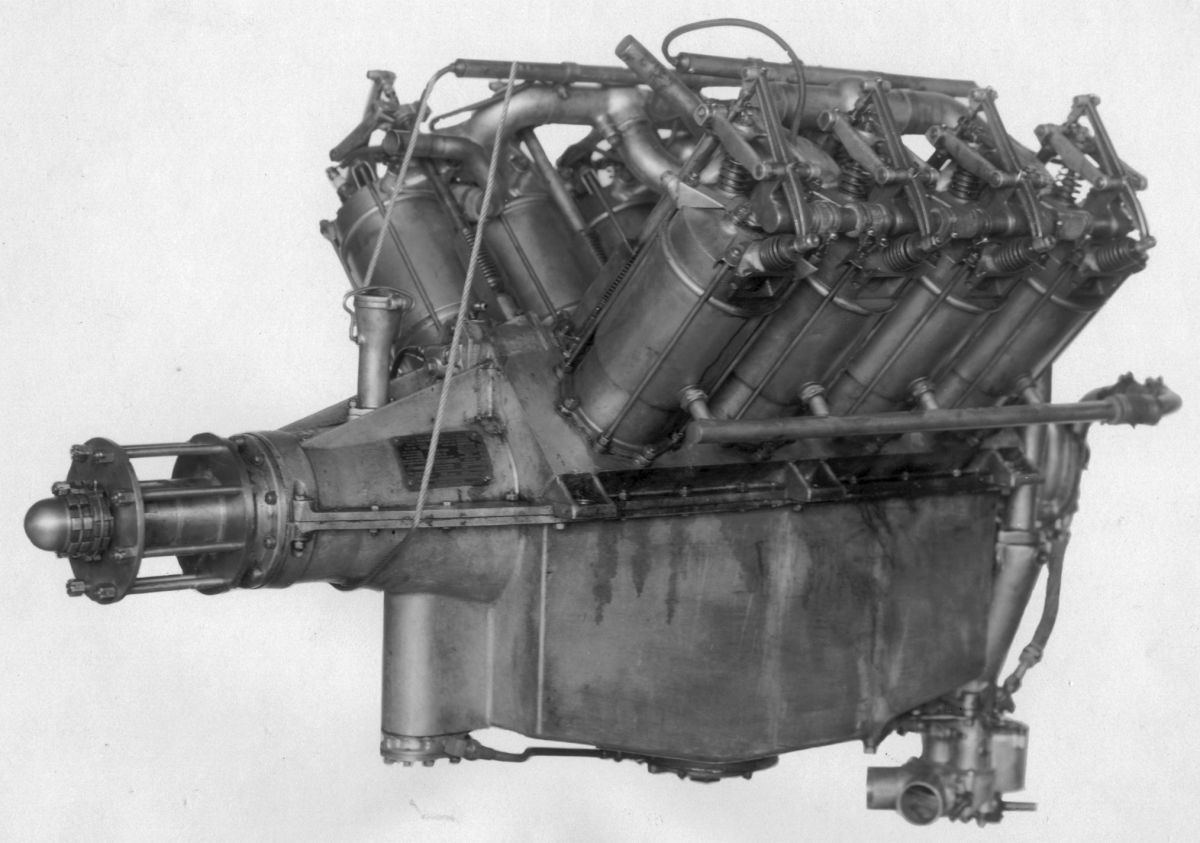
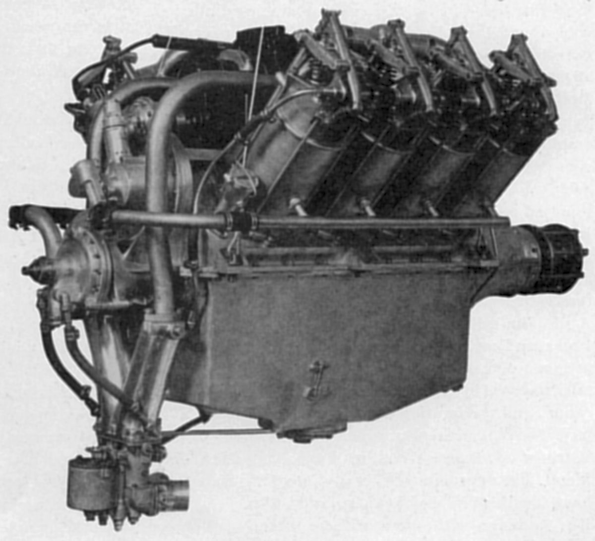
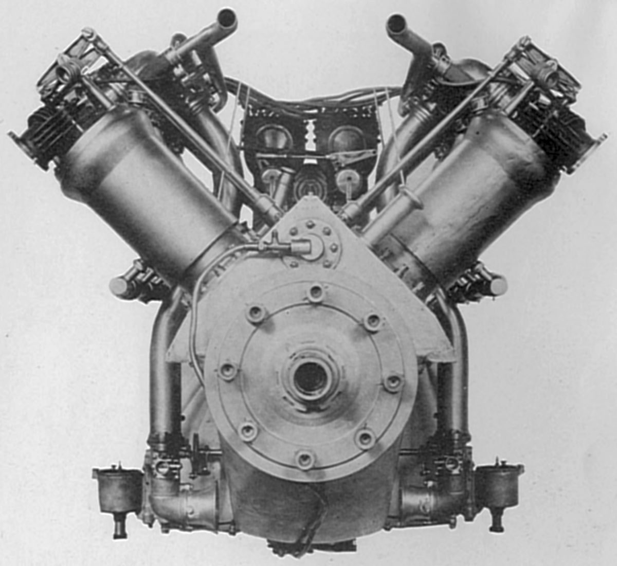
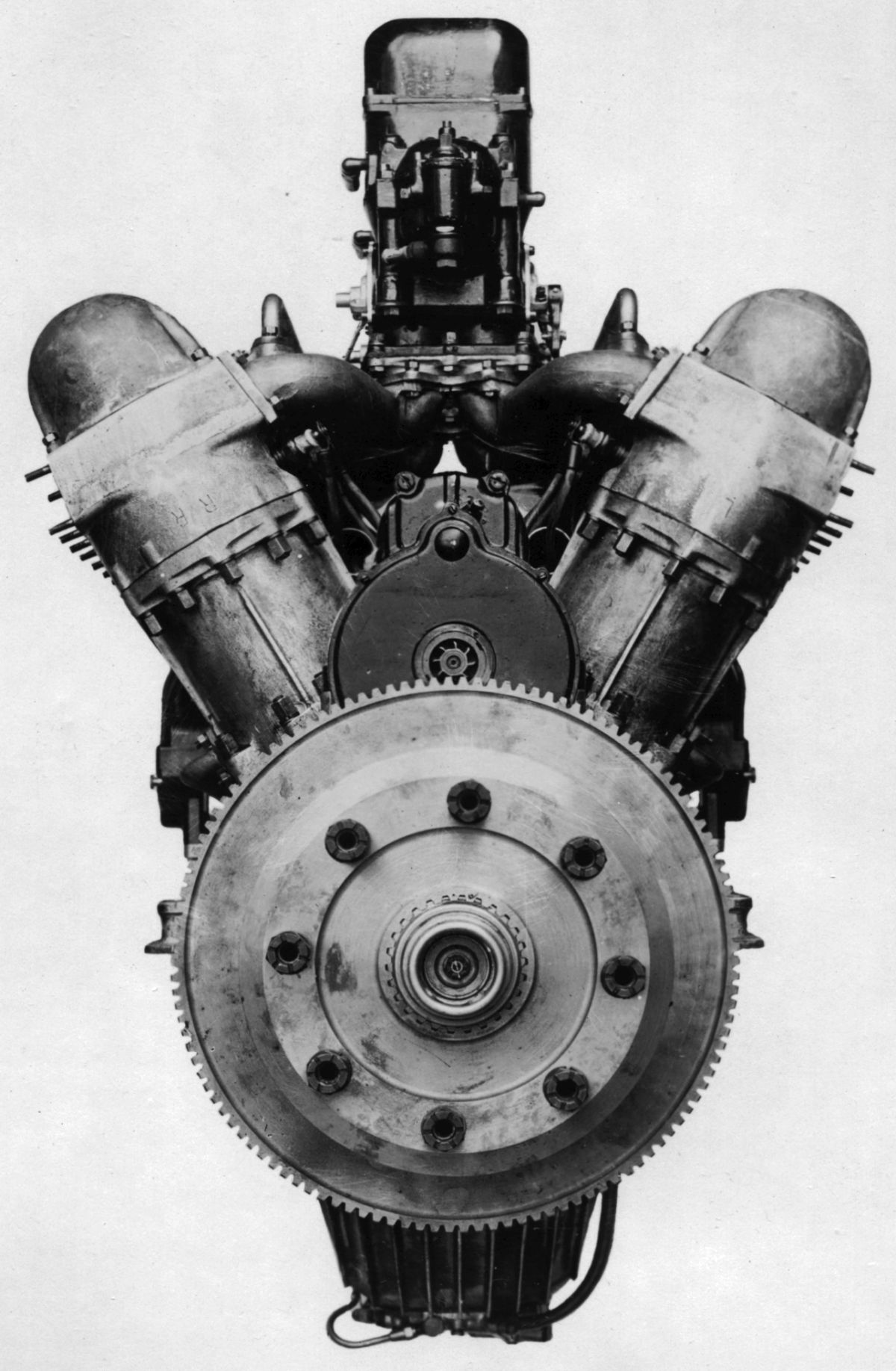
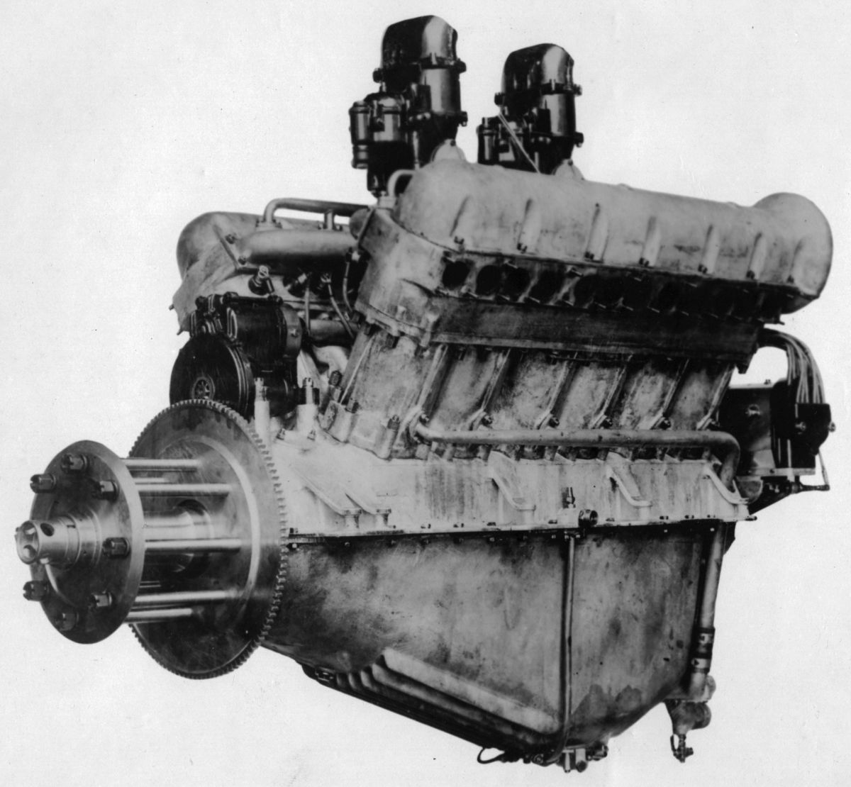
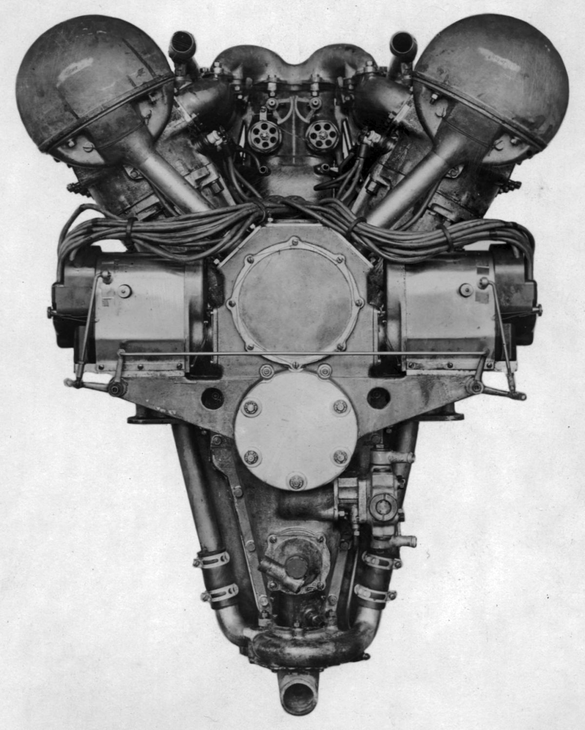
The Curtiss V-3 was a water-cooled 90° V-8 with a (guess what) 5.00" bore, 7.00" stroke and 1,099.6 in³ displacement rated 160 hp at 1,400 rpm. The aluminum alloy cylinders with detachable cylinder heads two inlet and two exhaust valves. The V-3 was designed by Charles M. Manly to replace the original VX type. Several V-3s were built and sold to the Russian government, but were never delivered as the ship carrying them was sank. An airplane, the America, was equipped with a V-3 engine and being prepared for a transatlantic flight in 1914, through the financial assistance of John Wanamaker.
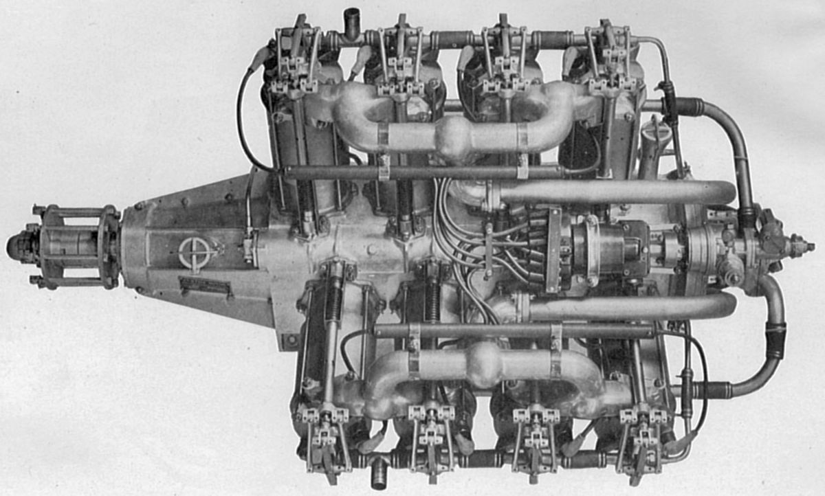
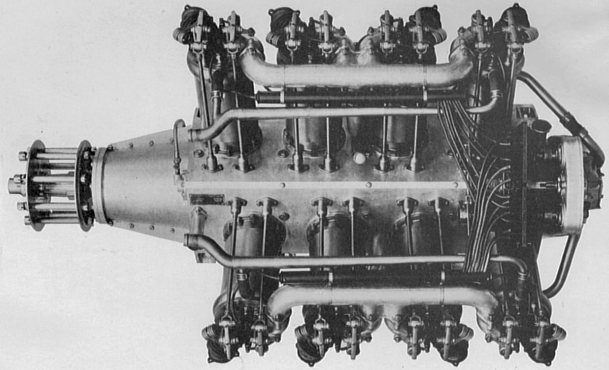
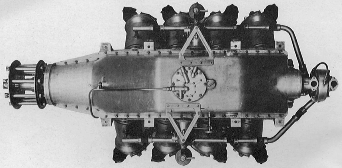
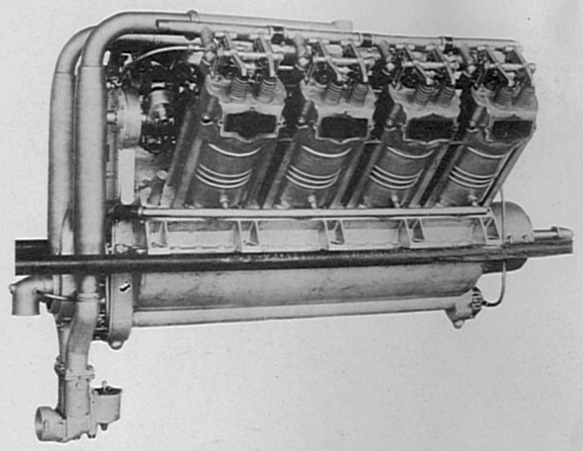
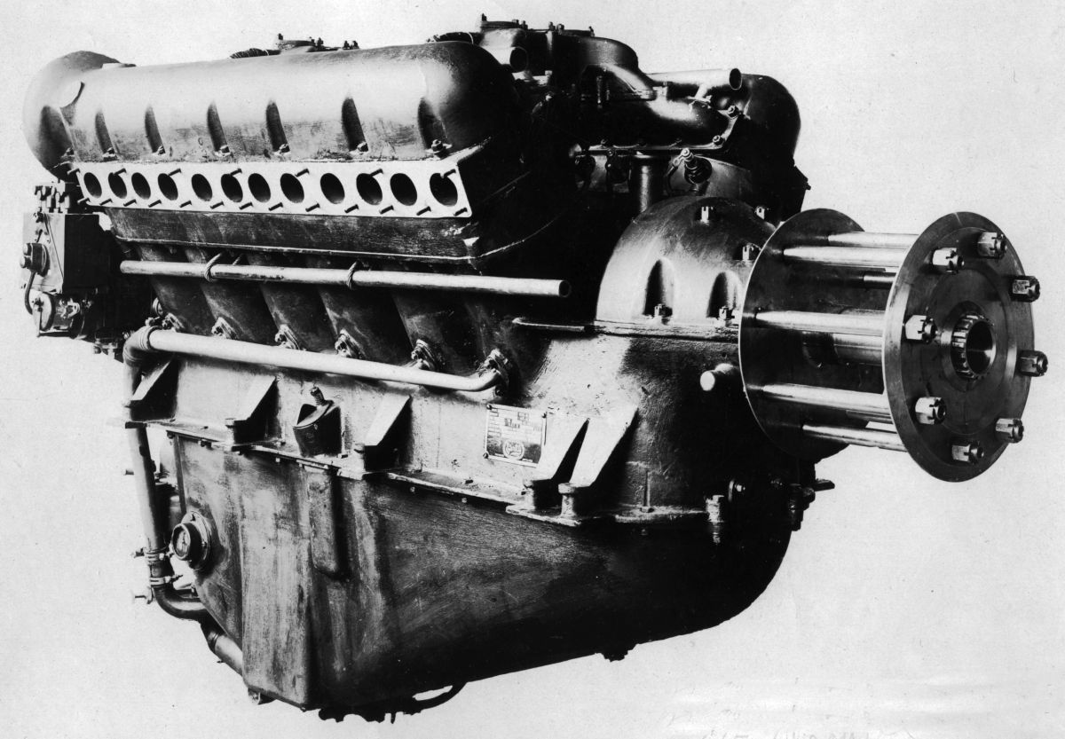
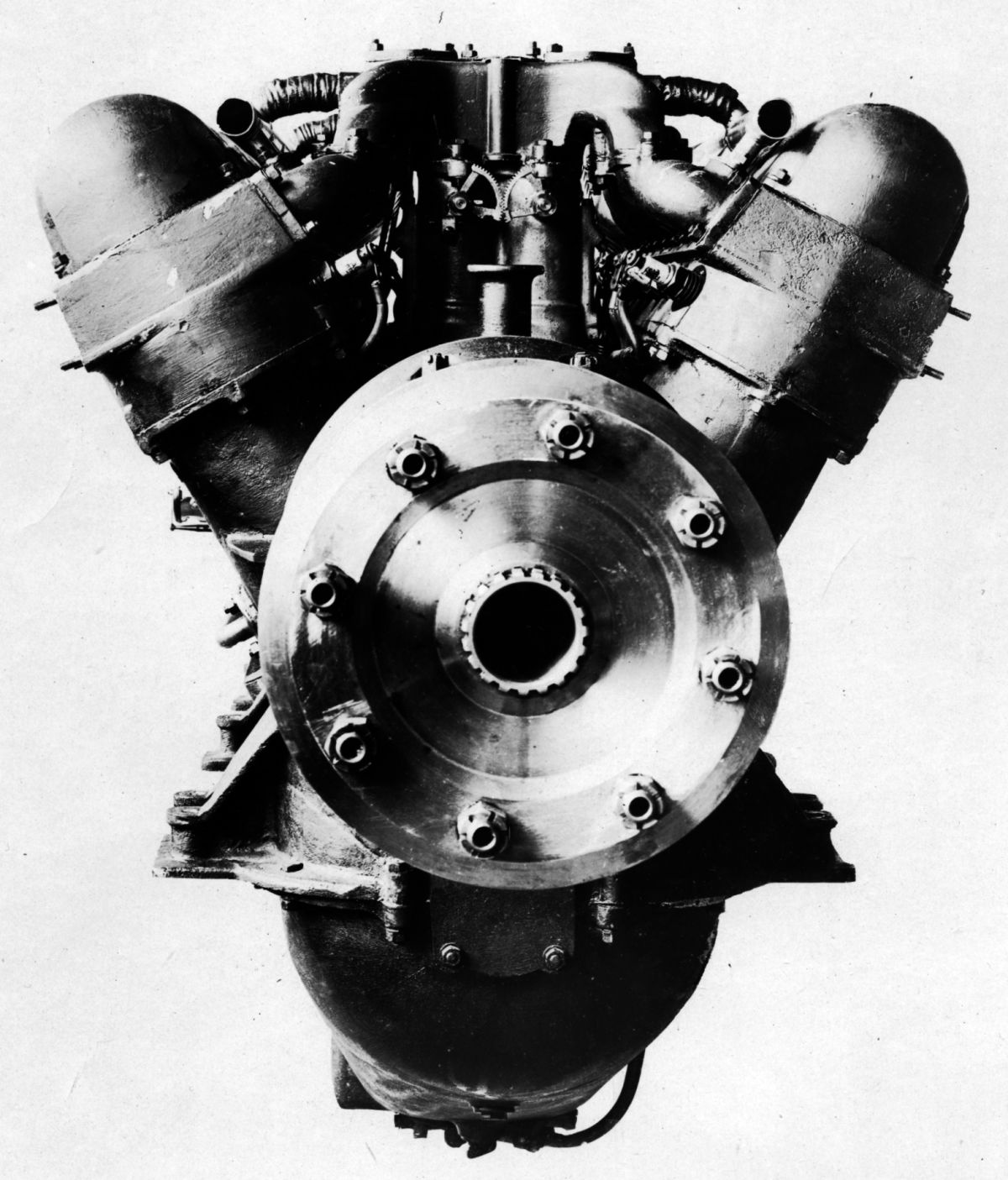
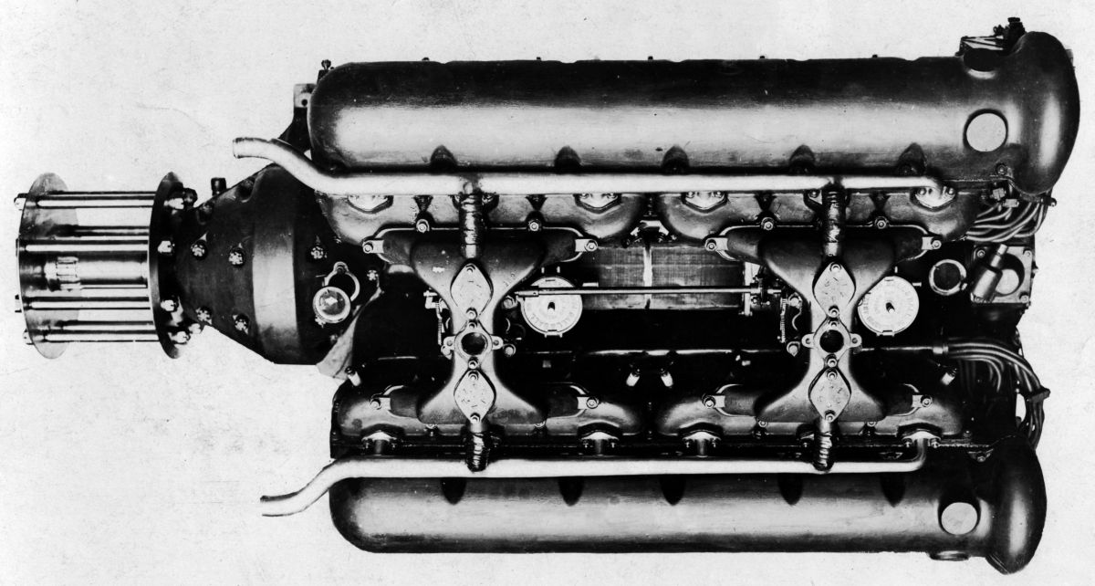
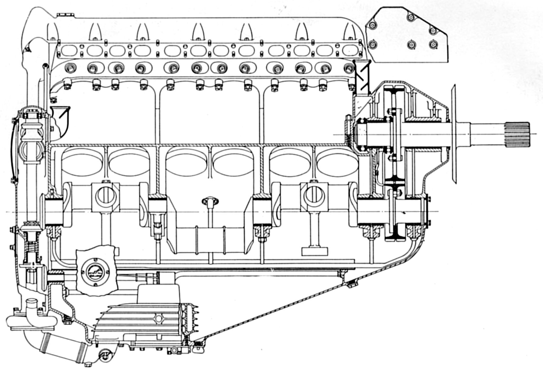
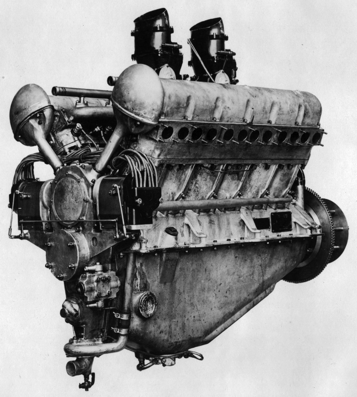
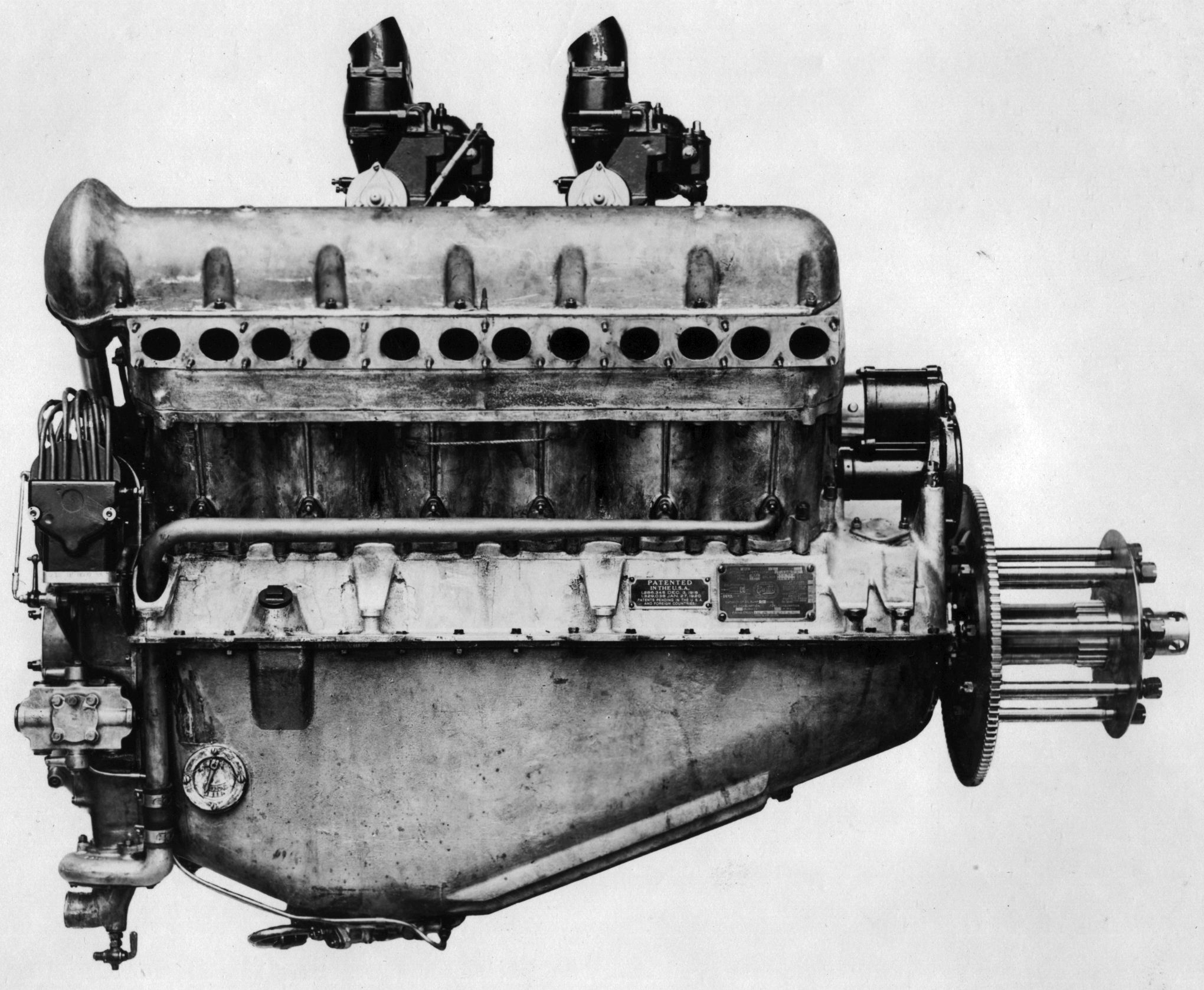
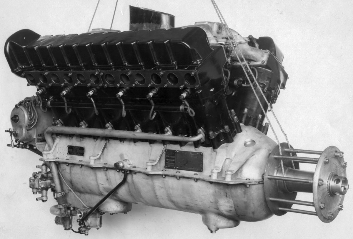
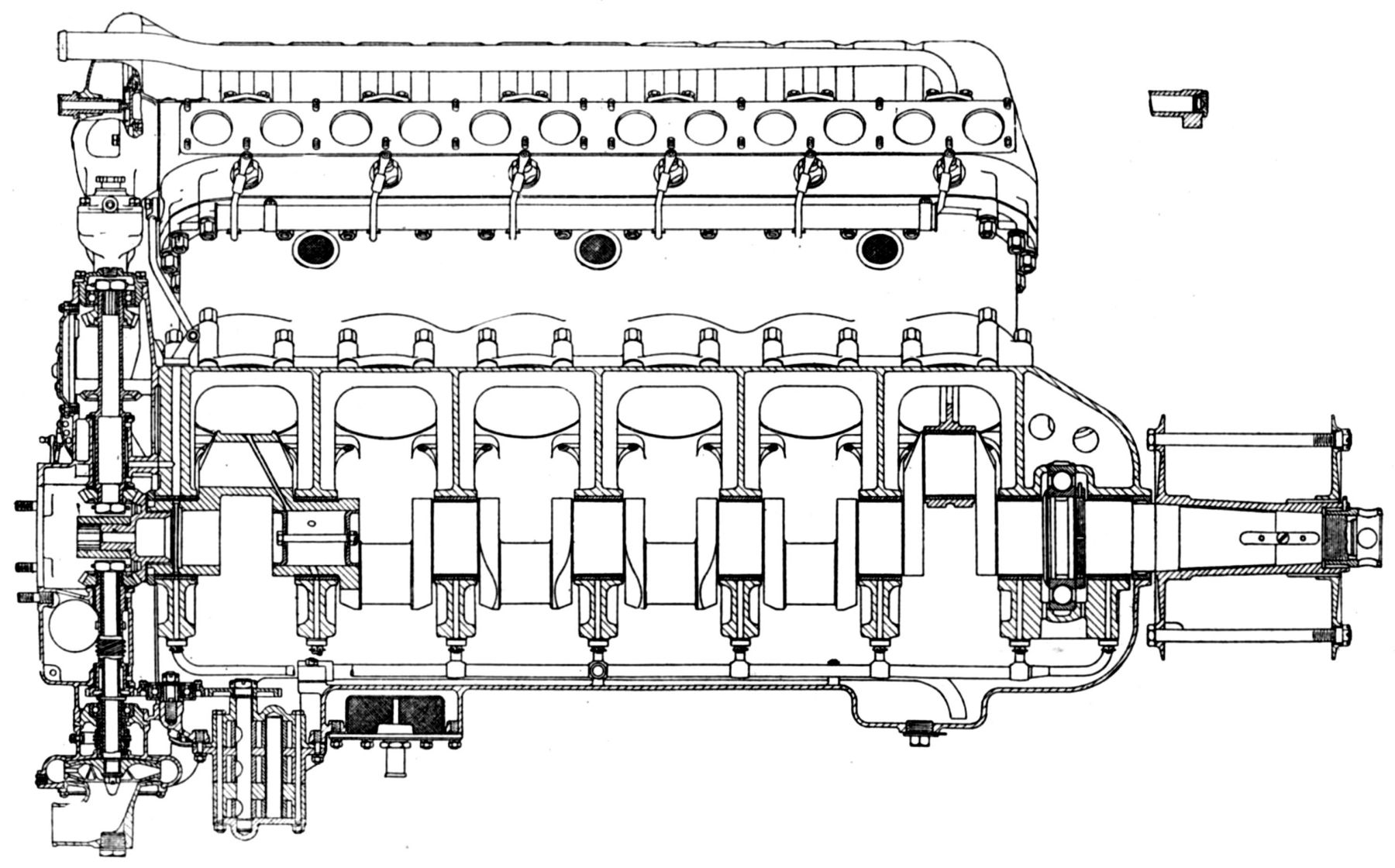
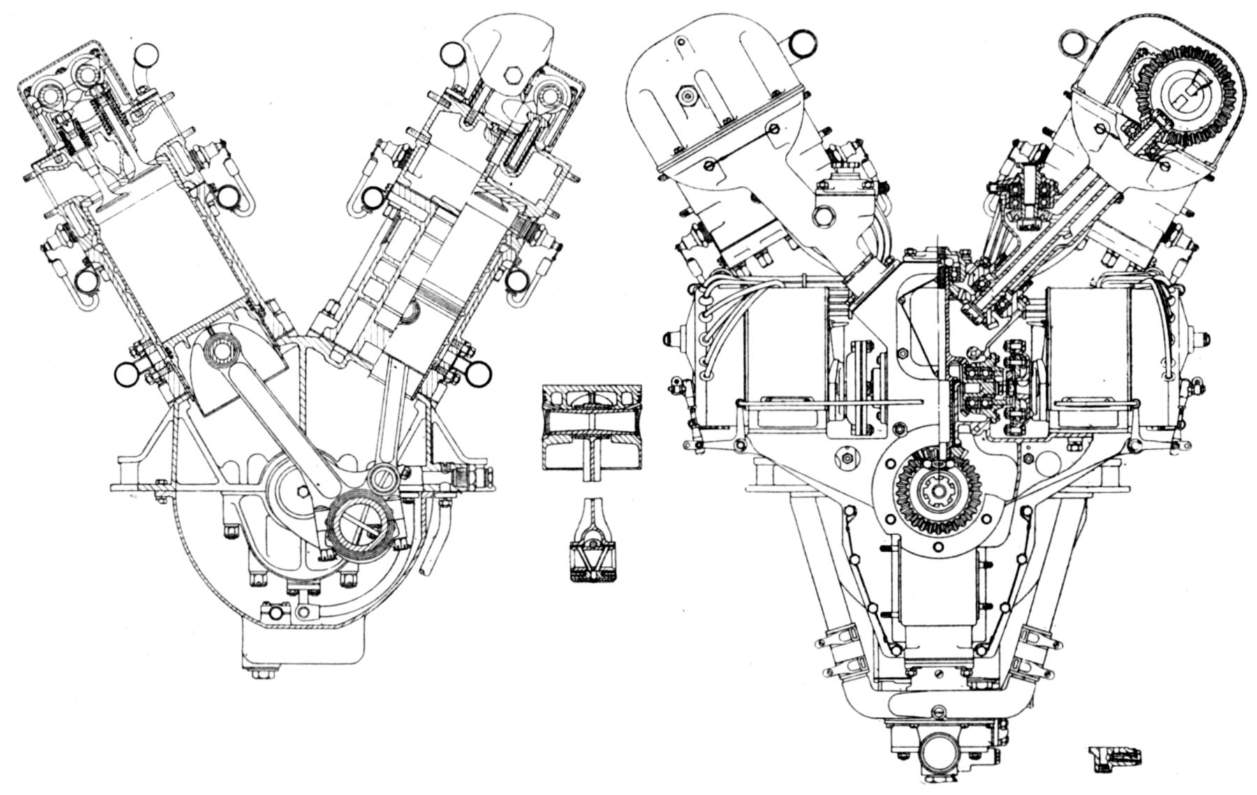
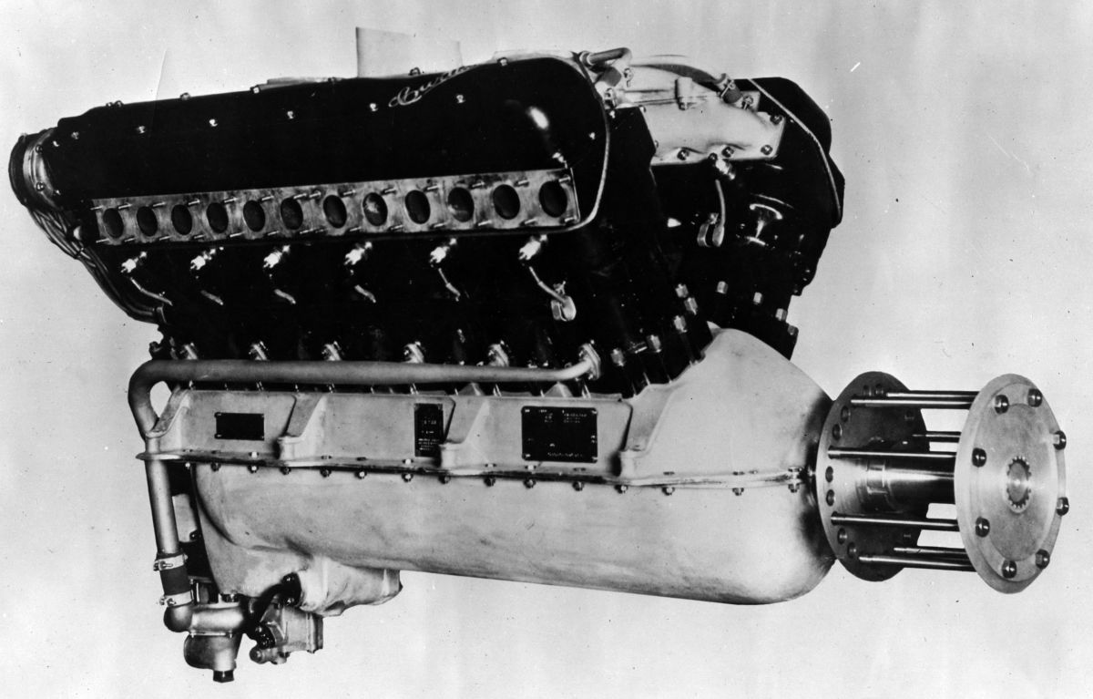
The Curtiss K-12 water-cooled V-12 was designed and built during 1917 – 1918 following a thorough study, along with construction and test of an experimental V-12 with a 4.00" bore, 5.00" stroke and 754.0 in³ displacement then known as Model AB. The K-12 was particularly adaptable to high-speed combat aircraft due to its low frontal area and specific weight. However, it was never fully developed because the U.S. Government during WWI had decided to concentrate on the production of Liberty 12s. A Curtiss Wasp triplane, designed around the K-12 by Kirkham and flown by Roland Rolfs, held the world's speed and altitude records for unsupercharged engines. The K-12, a water-cooled 60° V-12 with a 4.50" bore, 6.00" stroke, 1,145.1 in³ displacement and 5.63:1 compression ratio was rated 375 hp, but developed 397 hp at 2,250 rpm. Its normal bmep was approximately 122 psi and its maximum bmep, which occurred around 1,700 rpm, was 129 psi. The propeller shaft was mounted on plain bearings and driven at a 5:3 ratio through gears with staggered herringbone teeth. Dry weight was 678.5 lb, or 1.7 lb/hp. Cooling water in the jackets weighed 38.25 lb. The K-12 was 60" long, 27.875" wide and 40.125" high. A cylinder assembly consisted of a detachable aluminum alloy head into which were screwed six cylinders having combustion chambers and barrels that were machined from steel forgings. The aluminum alloy jacket around the barrels was part of the crankcase. A flange at the crankcase water jacket wall top mated with the detachable cylinder head, which was cored out for water passages around the head and valve ports. A cork packing ring between the crankcase and each cylinder barrel's lower end made a water-tight joint above the crankcase. Standing vertically in each cylinder were two inlet and two exhaust valves with 1.625" clear diameters, 0.406" lift, and 45° seats. The inlet valves opened at top center and closed 38° late; the exhaust valves opened 48° early and closed at top center. Each valve pair was operated from an overhead camshaft through a T-shaped intermediate piece that was guided in the head to relieve valve stem side loads. Screw adjustments at the T piece ends provided independent clearance adjustment for each valve stem. The exhaust camshaft was driven from its aft end by a driveshaft and bevel gears, the driven gear being bolted to a camshaft flange through a series of holes that gave a vernier timing adjustment. The inlet camshaft was driven from the exhaust camshaft by two herringbone gears. Camshafts were supported in six aluminum double bearings that were bolted to the cylinder head, and the entire valve gear was enclosed in an oil-tight cover. The six-throw crankshaft ran in five plain bearings, one being just ahead of the propeller drive gear. The crankshaft had counterbalance provisions, although these were generally omitted. The H-section connecting rods were of the articulated type, the link rod being forked at the crankpin end. The aluminum pistons were ribbed underneath the head and fitted with three rings. Fuel consumption was 0.499 lb/hp/hr and oil consumption 0.053 lb/hp/hr. A Ball and Ball duplex carburetor with 1.375" venturis and 210-mm jets furnished the mixture. The dry-sump lubrication system circulated 50% castor oil at a normal pressure of 80 psi via a gear pump. Two Berling D-66 magnetos, one for each cylinder bank, provided dual ignition.
 |
 |
 |
 |
 |
 |
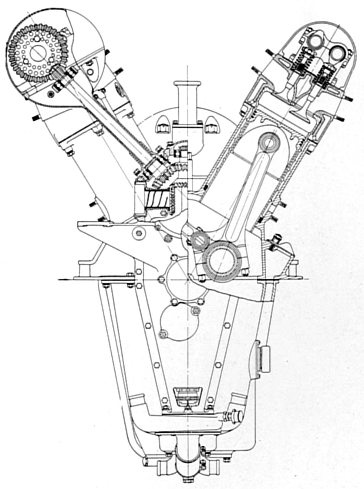 |
| Curtiss K-12 (NARA, AEE) | ||||||
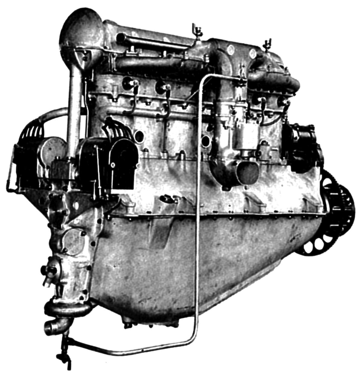
Curtiss followed the K-12 with the K-6 water-cooled direct-drive vertical six using the same cylinder block and crankshaft dimensions yielding a 572.6 in³ displacement, which, in conjunction with a 4.91:1 compression ratio, was rated 150 hp at 1,700 rpm. Its fuel consumption was 0.52 lb/hp/hr and its oil consumption 0.03 lb/hp/hr. It was 63" long, 22.125" wide and 39.25" wide. K-12 parts were used wherever possible in the K-6 The camshaft driveshaft stood vertically and drove the exhaust camshaft by means of skew bevel gears. The crankshaft had five plain main bearings and a forward ball bearing that carried the propeller thrust.
 |
 |
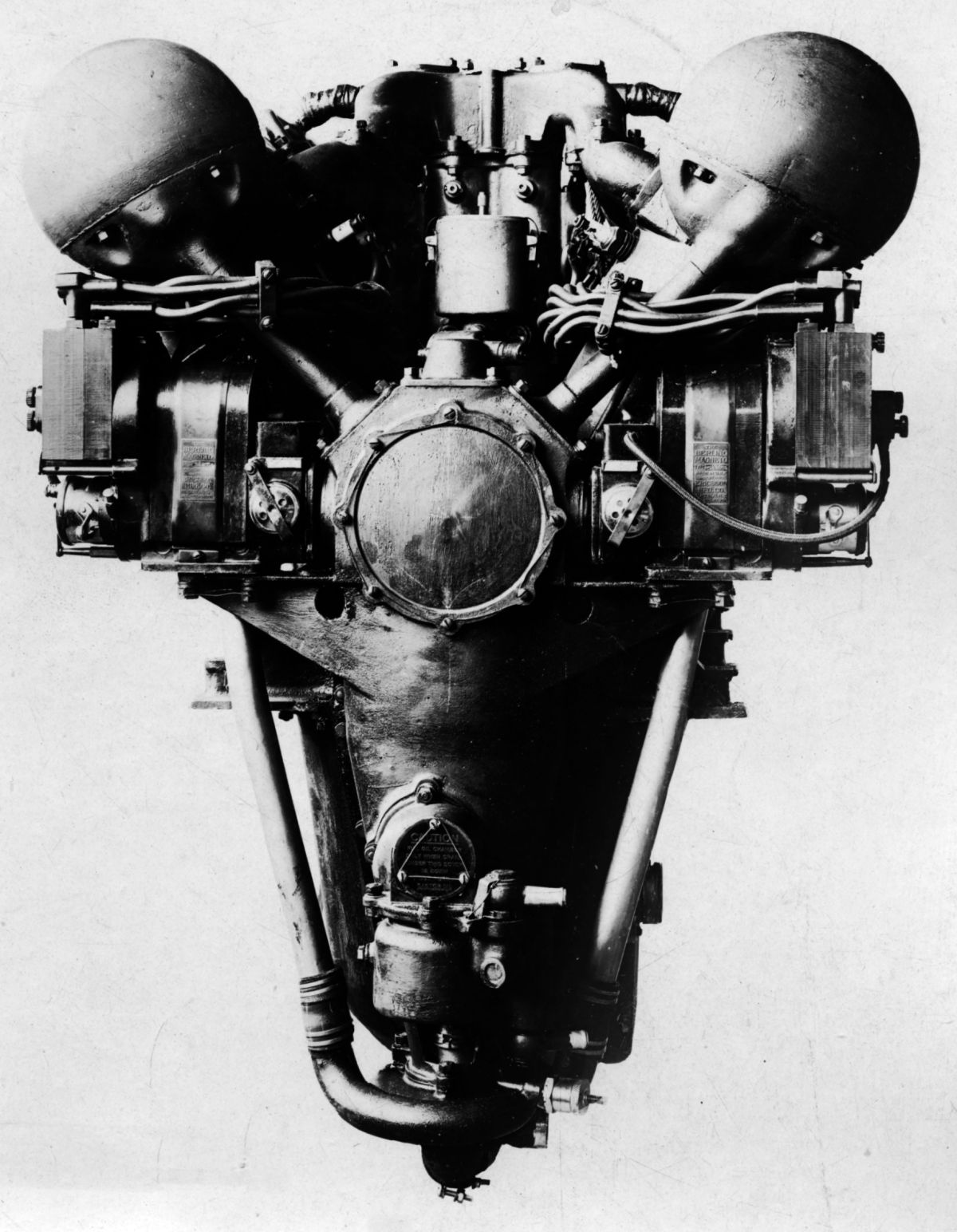
| Curtiss C-12, C-6 (AEE) | |
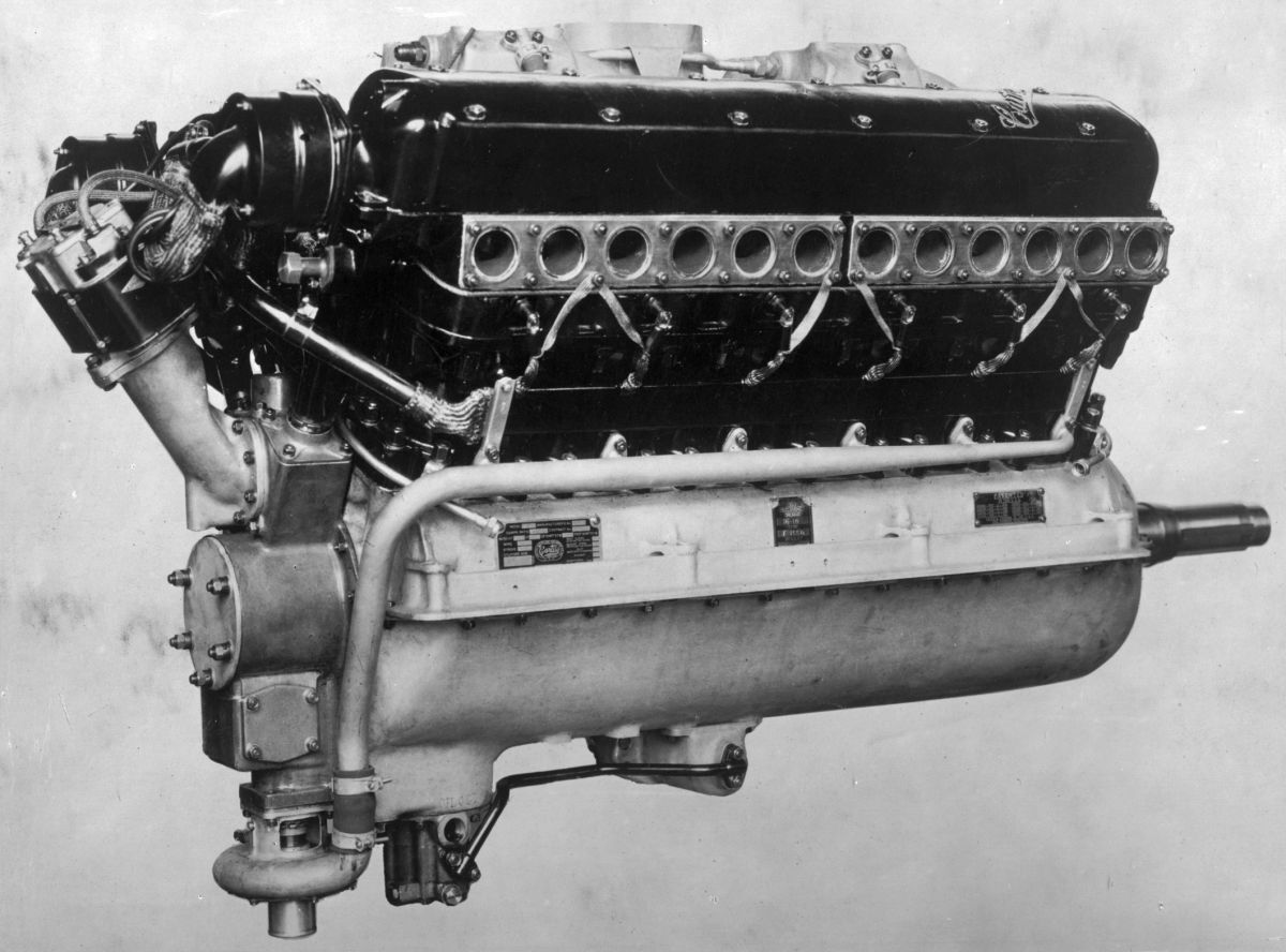
The Curtiss C-12 was a redesigned K-12 incorporating several changes. The packing gland at the cylinder barrel lower extremity was omitted by bolting the aluminum cylinder jacket to the crankcase instead of casting it integrally. Without changing cylinder center distances, three intermediate main bearings were added by reducing the crankpin bearing widths. Spark plugs were located diametrically opposite instead of both inside the Vee. The C-12 engine was rated at 400 hp, but developed 427 hp at 2,200 rpm The normal bmep was 131 psi. Fuel consumption was 0.503 lb/hp/hr and oil consumption was 0.083 lb/hp/hr. Dry weight was 705 lb, or 1.649 lb/hp.
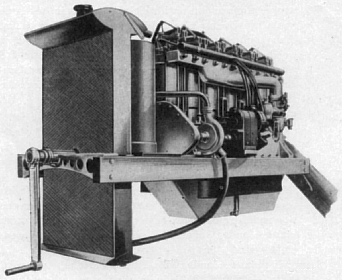
The C-6 was a redesigned model K-6 engine, developing 161 hp at 1,750 rpm and 127 psi bmep. Fuel consumption was 0.50 lb/hp/hr and oil consumption 0.016 lb/hp/hr. The engine weighed (dry) 448 lb, or 2.79 lb/hp.
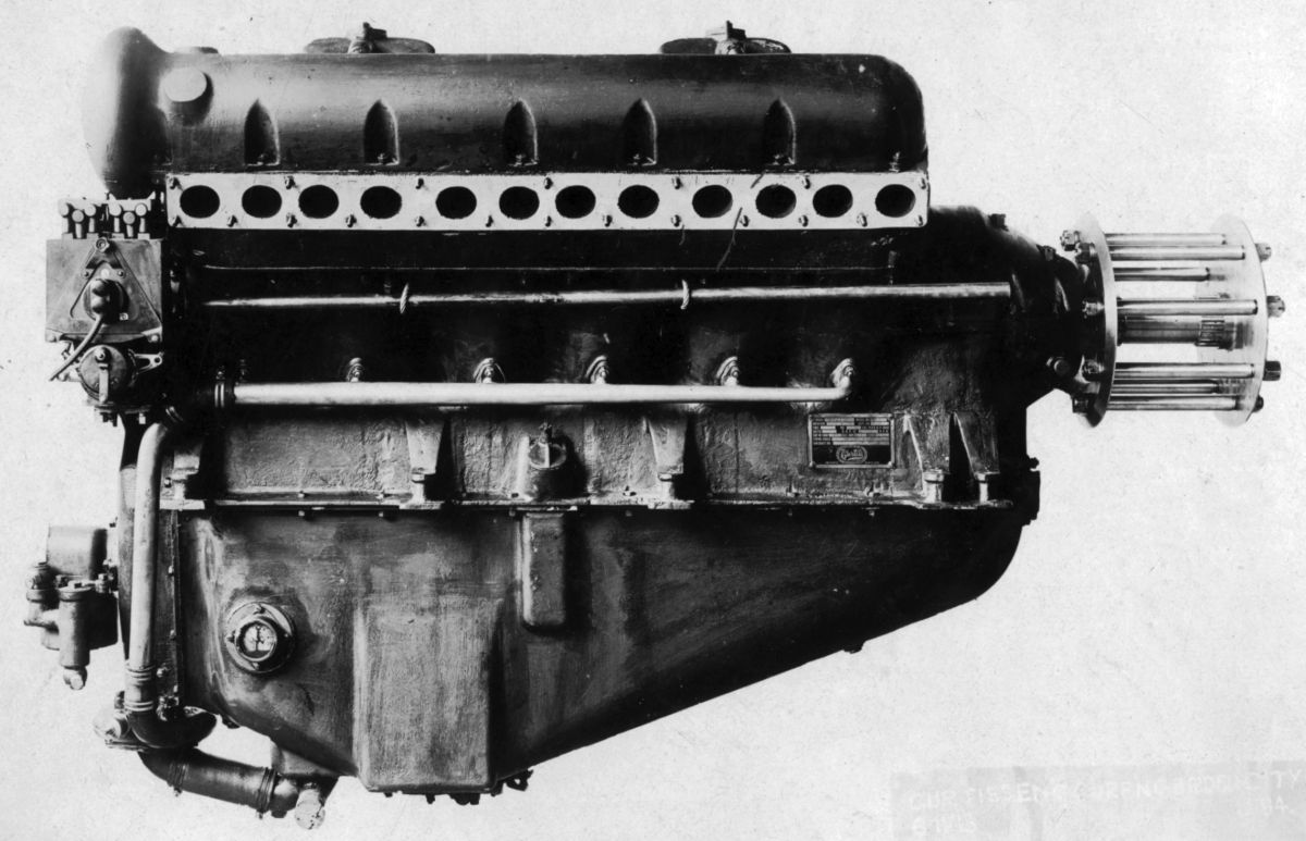
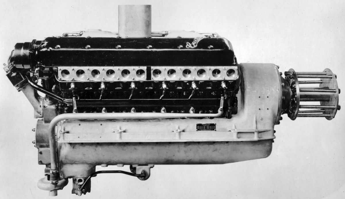
The Curtiss CD-12 with a direct-driven propeller was rated 325 hp at 1,800 rpm.. The omission of reduction gearing saved 25 lb in weight and 11" in length.
 |
 |
 |
 |
 |
| Curtiss CD-12 (NARA) | ||||
During 1921, Curtiss built the R-6, a water-cooled vertical six-cylinder for the U. S. Navy. An experimental engine with a 7.00" bore, 8.00" stroke, 1,847.3 in³ displacement, and incorporating the Ricardo supercharging principle, the R-6 was rated 400 hp at 1,450 rpm.
 |
 |
 |
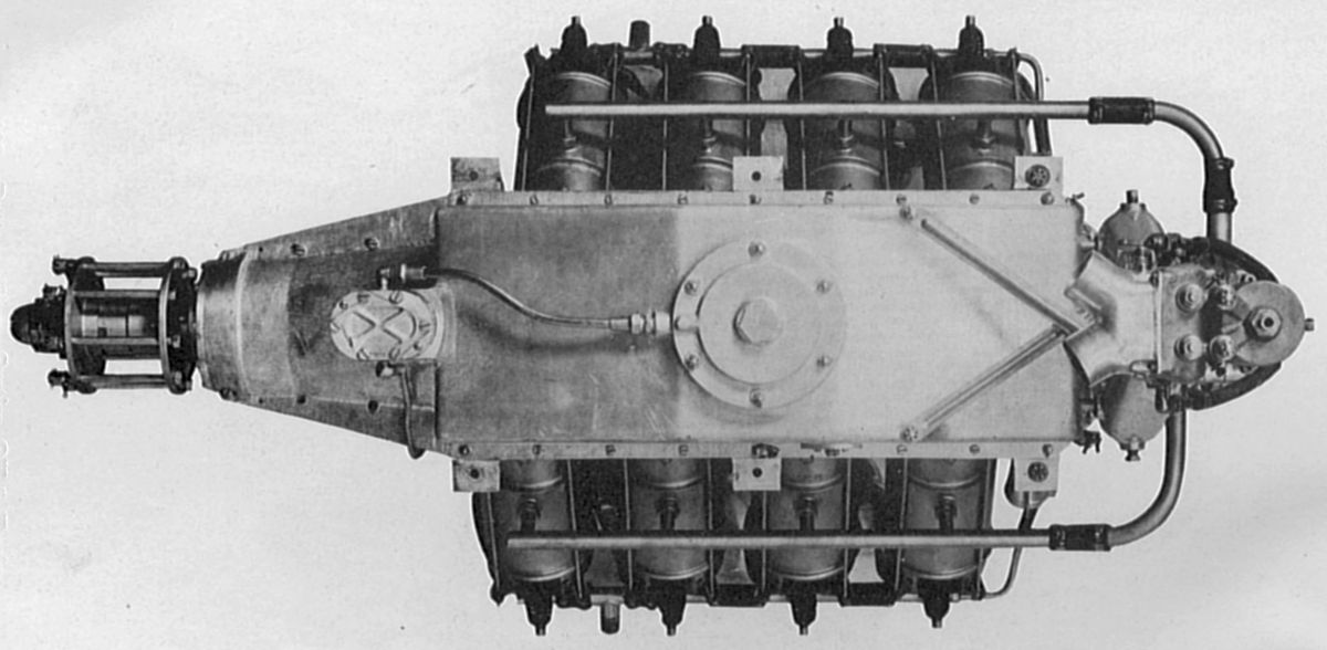
| Curtiss D-12 (NARA, AEE) | ||
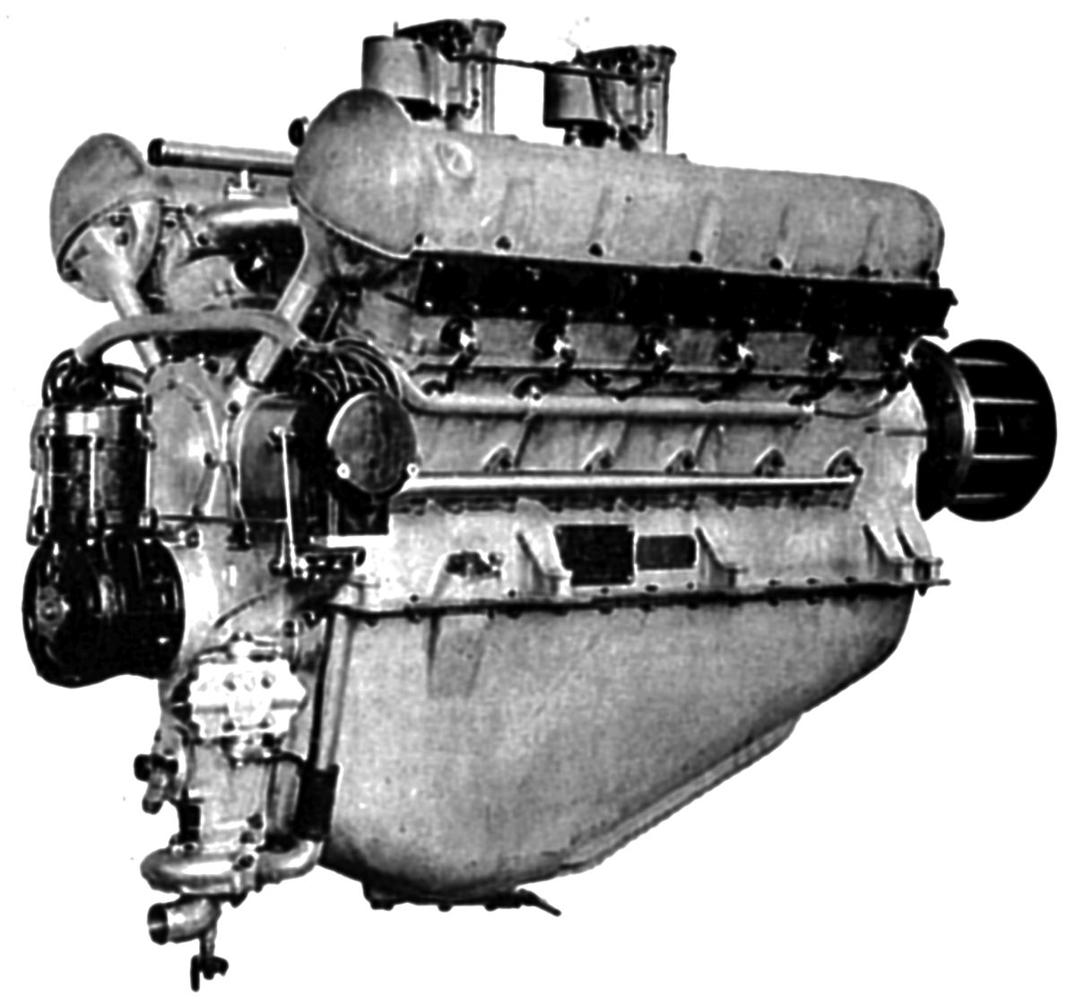
The Curtiss D-12 resulted from U.S. Army Air Service tests on C-12 and CD-12 models that suggested several design changes. Following Army recommendations, Curtiss engineers created a direct-drive, water-cooled upright V-12 with a properly-proportioned seven-main-bearing crankshaft and new cylinder spacing. The D-12 became famous due to its outstanding performance in Curtiss racing aircraft starting in 1922. A license was granted to the Fairey Aviation Co., Ltd., Middlesex, England, and the engine influenced several other European engine designs. The D-12 had a 4.500" bore, 6.000" stroke, 1,145.1 in³ displacement and produced 375 hp at 1,850 rpm. A 5.3:1 low-compression-ratio version delivered 431 hp at 2,200 rpm and weighed 693 lb, or 1.607 lb/hp. A 6:1 high-compression version produced 443 hp at 2,200 rpm and weighed 694 lb, or 1.566 lb/hp. Fuel consumption was 0.51 - 0.54 lb/hp/hr and oil consumption was 0.010 lb/hp/hr.
In 1923 Navy-Curtiss racing aircraft were fitted with the D-12A, which was a standard D-12 with a 0.125" cylinder bore increase. Now with a 4.625" bore, 6.000" stroke, 1,209.6 in³ displacement and 5:8:1 compression ratio it developed 507 hp at 2,300 rpm.
The standard D-12D of 1926 with a 5.3:1 compression ratio was rated 435 hp at 2,300 rpm and weighed 680 lb, or 1.56 lb/hp. The 6:1 high-compression version was rated 430 hp at 2,100 rpm but delivered 475 hp at 2,300 rpm and 490 hp at 2,500 rpm. Fuel consumption was 0.53 lb/hp/hr and oil consumption was 0.015 lb/hp/hr. This engine was 56.75" long, 28.25" wide and 34.75" high. It was equipped with Scintilla magnetos and two Stromberg NA-Y5-D carburetors. On 11 Oct 1928, the Department of Commerce granted Approved Type Certificate No. 10 to the D-12 engine with a rating of 435 hp at 2,300 rpm.
 |
| Curtiss V-1400 (NARA) |
The Curtiss V-1400 was developed from the D-12 for the 1925 Pulitzer Races. Although smaller and lighter, the V-1400 used larger cylinders and developed more power than the D-12. With a 4.875" bore, 6.25" stroke, 1,399.9 in³ displacement and 5.5:1 compression ratio, its normal rated output was 510 hp at 2,100 rpm. The dry weight was 660 lb, or 1.29 lb/hp. It was 51.06" long, 26" wide and 35.7" high. Fuel consumption was 0.53 lb/hp/hr. The V- 1400 was 51" long and 26" wide. The V-1400 employed open sleeves, instead of closed-end steel sleeves, that were screwed into the aluminum alloy cylinder block and head. Larger valves seated upon aluminum-bronze inserts.
 |
 |
 |
| V-1570, Direct Drive, Geared, Supercharged (NARA) | ||
The V-1570 Conqueror was another D-12 development. With a 5.125" bore, 6.250" stroke and 1,547.2 in³ displacement, its rated output was 600 hp at 2,400 rpm and its weight was 770 lb, or 1.26 lb/hp. Fuel consumption was 0.53 lb/hp/hr and oil consumption was 0.015 lb/hp/hr. The engine was 51" long, 26" wide and 35.6875" high. The Department of Commerce issued Approved Type Certificate No. 6 to the Curtiss Conqueror V-1570 engine on 31 Aug 1928 with a rating of 600 hp at 2,400 rpm. On 12 Apr 1932, the Type Certificate was revised to read the Wright Conqueror V-1570C, including the A and B (Curtiss and Wright merged in 1929). Then on 21 Oct 1932, another revision specified the Wright Conqueror V-1570F, including the A, B and C. The rating was increased to 650 hp at 2,400 rpm by the revision dated 27 Nov 1932. Dry weight of the later model was 890 lb, or 1.37 lb/hp. The V-1570F was 64" long, 29.5625" wide, and 39.25" wide. Conqueror engines could be installed on the same engine bearers as the D-12. Cylinder and block construction followed the V-1400. The crankshaft main journals and connecting rod shanks were increased in size to handle the increased output. Valve gear consisted of the usual T-shaped cam followers and double camshafts, but two cam bearings on each block were eliminated to reduce weight. Like the V-1400, the frontal area was reduced by using three spur gears for driving the double camshafts, the third gear or idler, with the bevel gear attached, being below the others. A dry-sump lubrication system with gear-type pumps was employed. Two Stromberg NA-Y6-D carburetors supplied the mixture and one double Splitdorf magneto supplied ignition.
Curtiss-Wright continued to improve the Conqueror for the remainder of the 1930s, offering various geared and supercharged versions. However, the liquid-cooled engine marked wavered profoundly as the U.S. Navy committed to air-cooled radials to power its aircraft. Wright did not build another big V-12.
 |
 |
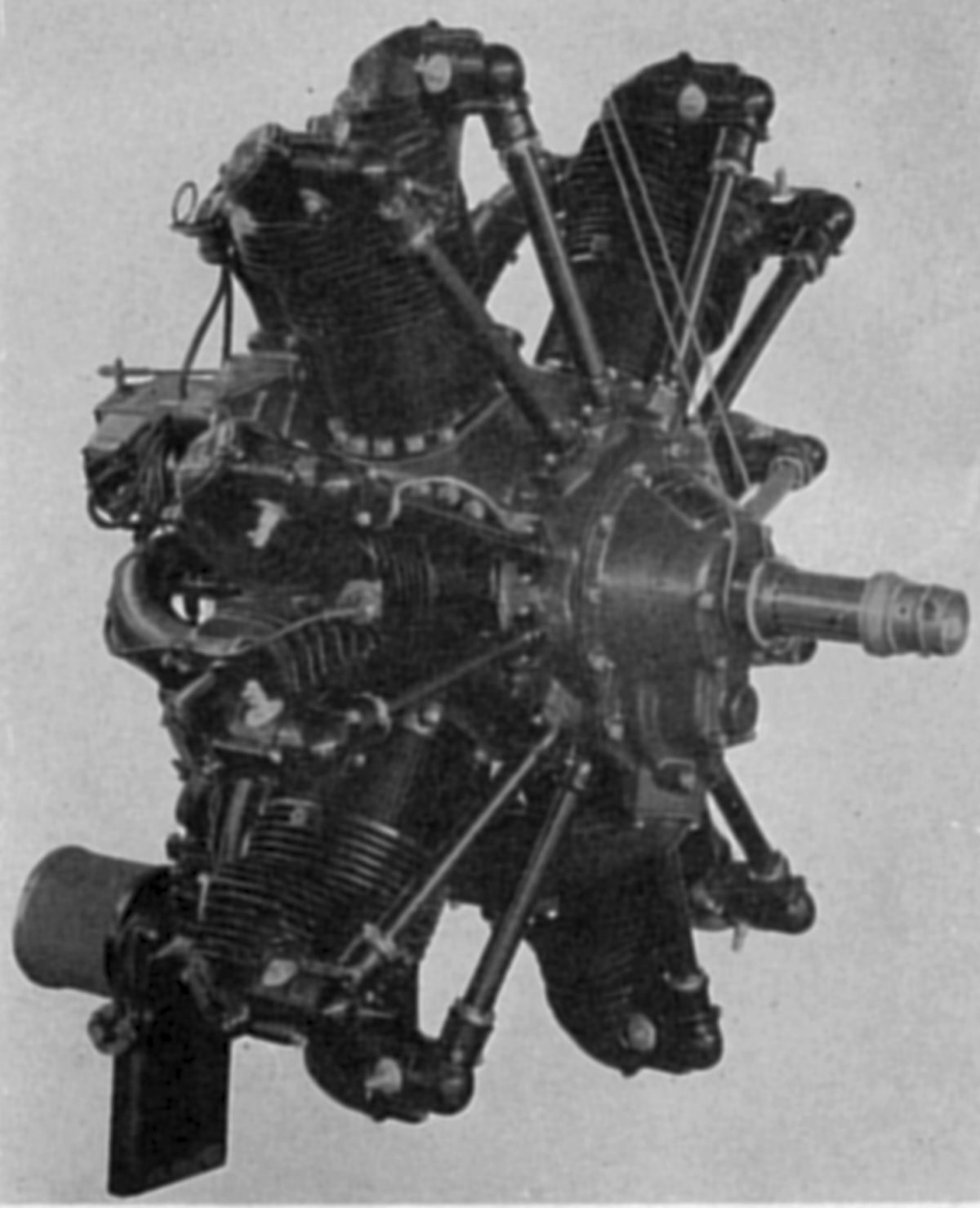
| Curtiss R-1454 (NARA) | |
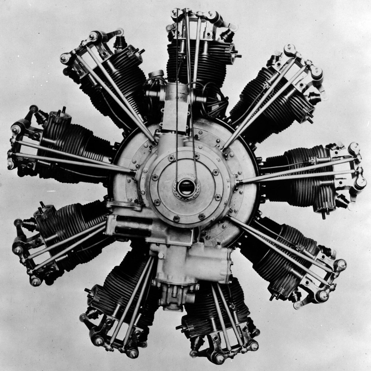
The R-1454 was the first Curtiss air-cooled radial. A single-row nine-cylinder developed under contract and in conjunction with the Army Air Service during 1924, it had a 5.625" bore, 1,453.7 in³ displacement and 5.4:1 compression ratio. Weighing 790 lb, its rated output was 400 hp at 1,750 rpm, or 1.97 lb/hp. Its outside diameter was 52.75". Cylinders consisted of steel barrels with integral cooling fins that were screwed and shrunk into cast aluminum-alloy heads. The valves were inclined to the axis of the cylinder and seated upon shrunk-in aluminum bronze valve seats. The exhaust valve was salt-cooled. Valve operation was by means of push rods and rocker arms with bearings in an oil-tight bracket supported by the cylinder head. A rotary induction system, fed by a single Stromberg carburetor, was built into the engine rear.
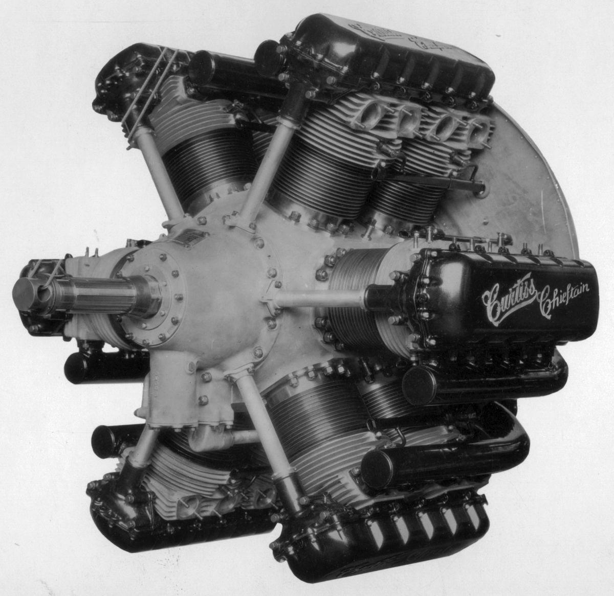
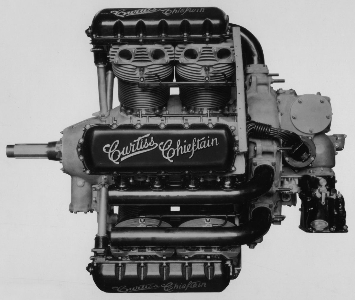
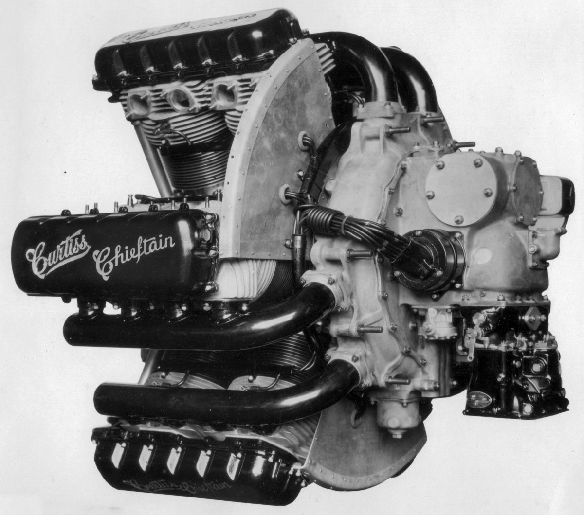
Curtiss introduced the H-1640 Chieftain, a twelve-cylinder air-cooled radial in 1928. With two rows of six cylinders arranged directly one behind the other, a 5.625" bore, 5.500" stroke, 1,640.1 in³ displacement and 5.1:1 compression ratio, it produced 600 hp at 2,200 rpm. Fuel consumption was 0.53 lb/hp/hr and oil consumption was 0.02 lb/hp/hr. Length was 52.313", outside diameter 45.25" and weight 915 lb. The H-1640 received Approved Type Certificate No. 8 on 13 Sep 1928. The individual cylinders had steel barrels with integral cooling fins that were screwed and shrunk into cast aluminum-alloy heads. Each cylinder had four valves seating upon bronze inserts in a flat head. At each cylinder top was a large spigot that fitted into a casting bridging two cylinders and held to them by studs and nuts. This casting carried two camshafts driven by spur gears at the propeller end; one spur gear was mounted on an idler shaft below and driven through bevel gears from a driveshaft having a bevel gear at the inner end meshing with a master gear on the crankshaft. The timing of each camshaft pair was adjusted by a serrated face coupling. The cylinder head and valve mechanism was very similar to Conqueror valve gear. The crankshaft had two throws 180° apart and was mounted on roller bearings at the ends; a steel-backed white-metal-lined plain bearing at the center was mounted on a large split circular support with a diameter sufficient to clear both crankpins when the shaft was inserted into the crankcase. The split crankcase was joined in a plane between the cylinder rows at right angles to the crankshaft axis. Flanges interior to the crankcase were bolted together before the cylinders were installed. The nose section contained a cluster of bevel gears that drove the camshaft drive shafts. It also contained an oil strainer at the end of the pressure system, and a deep-groove ball bearing for carrying the propeller thrust load. The aluminum pistons were of conventional design with ribs underneath the heads. The master connecting rod had a split end held by bolts and keys; the five articulated rods were arranged symmetrically around the master rod center line. A centrifugal supercharger was mounted at the engine rear and driven through a jack-shaft and four spur gears. The mixture was fed through an elbow cast integral with the gear case from a Stromberg NA-U3J carburetor. The main shaft extended through the supercharger diffuser to provide a drive for other units mounted on the engine back. A large bevel gear drove horizontal cross shafts, at the ends of which were arranged the magneto and starter. A large helical gear drove two vertical shafts with oil and fuel pumps at the lower ends and two gun synchronizers. Two distributors were driven from these shafts through helical gears. A generator mounted vertically on top of the gearcase was driven through bevel gears. Oil passed through a steel tube from the pump to the front-mounted oil strainer before entering the crankshaft. All engine bearings were pressure fed. Oil for the camshaft bearings passed through the vertical drive shafts and was returned to the crankcase by gear-type scavenge pumps in the casing around the camshaft drive shafts. Double crankcase scavenge, one for the front end and one for the aft end, were provided. The H-1640 employed cross-flow air cooling where air under pressure in three plenums between every other cylinder bank flowed across the cylinder fins and exhausted via low-pressure plenums occupying the other three spaces between cylinder banks. Since the H-1640 was a radial with an even number of cylinders per row it had an unusual firing order, which is discussed in another article.
 |
 |
 |
 |
| Curtiss H-1640 Chieftain (NARA) | |||
 |
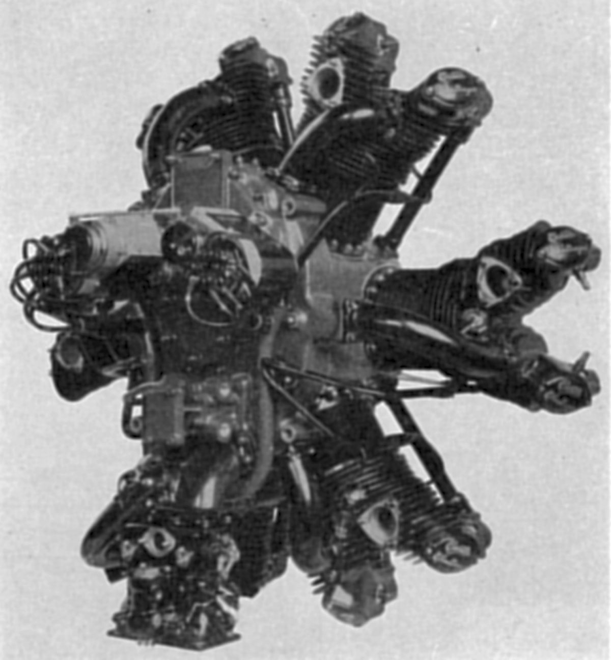 |
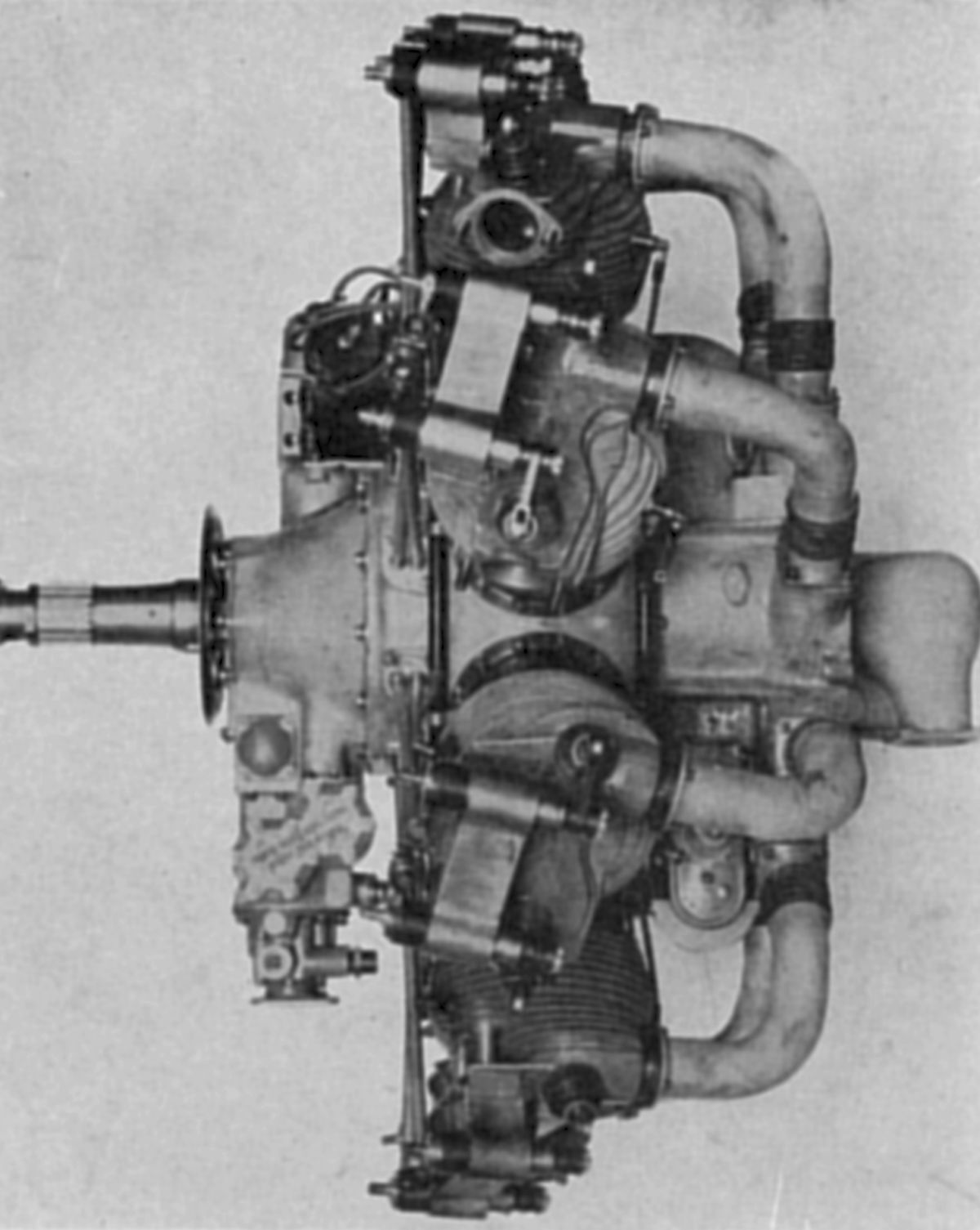
| Curtiss R-600 (A39) | |
The R-600 Challenger was an air-cooled six-cylinder radial with two staggered three-cylinder rows having a 5.125" bore, 4.875" stroke, a 603.4 in³ displacement and a 5.2:1 compression ratio. Its rated output was 170 hp at 1,800 rpm, and 185 hp at 2,000 rpm. Fuel consumption was 0.552 lb/hp/hr and oil consumption was 0.02 1b/hp/hr. Dry weight (minus starter and propeller hub) was 420 lb and the outside diameter was 42.625". The Department of Commerce granted Approved Type Certificate No. 5. to this engine on 26 Jul 1928. The cylinders were built from steel barrels with integral cooling fins that were screwed and shrunk into cast aluminum-alloy heads. The tulip-shaped valves, inclined from the cylinder axis, seated upon bronze seats shrunk into the head. The valves were operated by fully-enclosed push rods and rocker arms within rocker boxes cast integral with the cylinder head. The double cam mechanism was on the engine front and the valve ports faced aft. The two-throw crankshaft had small counterweights forged integrally with the outside cheeks. Three ball bearings supported the crankshaft, the most forward one resolving both radial and thrust loads. A master connecting rod with two articulated rods ran on each crankpin. The cast aluminum alloy pistons, ribbed underneath the heads, had two compression and two oil-control rings above the piston-pin and one oil-control ring below it. The crankcase was cast in two sections that were joined in a plane through the front cylinder row axis. The induction manifolds, four mounting bosses, and the accessory drive gear housing were cast integral with the crankcase rear half. All units at the engine rear were driven through spur gears. These included two Scintilla magnetos, pressure and scavenging gear-type oil pumps, and provision for standard types of starter, generator, plunger-type gun control, and an Army type C-5 fuel pump. The mixture was furnished by a Stromberg NA-U4J carburetor, which was exhaust-jacketed and arranged with a control valve to regulate the amount of heat applied.
References
Angle, Glenn D, ed. Aerosphere 1939 (New York, New York: Aircraft Publications, 1940).
Angle, Glenn D, ed. Airplane Engine Encyclopedia (Dayton, Ohio: Otterbein Press, 1921).
Image Sources: A39 = Aerosphere 1939; AEE = Airplane Engine Encyclopedia; Flt = Flight Magazine; NARA = U.S. National Archives and Records Administration; UKNA = United Kingdom National Archives.
Send mail to
![]() with questions or comments about this web site.
with questions or comments about this web site.
![]()