Selected Early Engines
Cirrus, Clerget, Cosmos, Curtiss
Compiled by Kimble D. McCutcheon
Published 6 Apr 2022; Revised 26 Apr 2022
Cirrus
Cirrus engines originated during Geoffrey de Havilland's search for an engine to power a light two-seat biplane design that would become the de Havilland Moth. The Aircraft Disposal Company, also known as Airdisco and ADC, was producing a low-cost air-cooled V-8 that Frank Halford (7 Mar 1894- 16 Apr 1955) had developed by from its large stock of war-surplus Renault V-8 aircraft engines. In 1924, de Havilland concluded that a four-cylinder inline based on the V-8 components would be ideal for his Moth and convinced Halford to design and develop it. Halford used surplus Renault cylinders, pistons, connecting rods and gearing, in combination with Airdisco valve gear, a new crankshaft and a new cast aluminum crankcase. The new engine went into quantity production in 1925 as the Cirrus Mark I.
Cirrus Aero Engines, Ltd. became an Airdisco subsidiary in 1925. In 1931, Cirrus Aero Engines Ltd. was reorganized as the Cirrus-Hermes Engineering Company, Ltd., building Cirrus Minor and Major engines at a new plant in East Yorks, England. In 1937, Blackburn Aircraft, Ltd. acquired the Cirrus assets.
Halford opened a consultancy in 1923 and designed the Gipsy piston engine series for de Havilland. Then, in concert with Harry Ricardo, Halford designed the Napier Rapier, Dagger, and Sabre. He then returned to help de Havilland with the Goblin, Ghost, and Gyron gas turbine designs.
The Cirrus Mark I, an air-cooled upright four-cylinder, was designed to power the first de Havilland Moth biplane. With a 105 mm (4.134") bore, 130 mm (5.118") stroke and 4.503 l (274.8 in³) displacement it developed 65 hp at 2,000 rpm and weighed 268 lb. Early Cirrus engines used individual finned cast-iron cylinder barrels with aluminum alloy heads held together by long studs extending to the crankcase. The valves, which seated upon expanded-in phosphor-bronze seats, were parallel to the cylinder centerlines and actuated by push rods and rocker arms from a camshaft with followers in the crankcase. The four-throw crankshaft ran on five main bearings, three plain intermediate bearings, roller bearings fore and aft, and an extra ball bearing forward to carry the propeller thrust. Mark I connecting rods were steel.
|
|
| Cirrus Mark II (A39) | |
The Cirrus Mark II, first produced in 1926, featured a 110 mm (4.331") bore, which raised its displacement to 4.942 l (301.6 in³). The cylinder head and connecting rods were also altered, resulting in an engine that produced 75 hp at 1,800 rpm and 84 hp at 2,000 rpm. Compression ratio was 4.9:1 and weight was 280 lb. The Mark II was 45.8" long, 18.26" wide and 34.3" high. Mark II Cirrus engines introduced H-section connecting rods made from forged duralumin. The integrally cast rocker-arm bracket used on Mark I cylinder heads were replaced by separate steel and duralumin brackets bolted to a flat bridge between the valve ports. The earlier single induction system was replaced by a duplex Zenith or Claudel-Hobson carburetor with one induction passage leading to the end cylinders and the other to the inner cylinders; both passages were exhaust heated. The aluminum pistons were fitted with three rings each, the lower one acting as a semi-oil-scraper ring. The crankcase was formed by two aluminum castings joined in a horizontal plane at the crankshaft centerline. The rather deep lower section formed an oil sump. Aluminum caps bolted to the crankcase upper section held the crankshaft bearings. The camshaft was carried in three plain phosphor-bronze bearings, and a spiral gear at the camshaft end drove an oil pump located in the sump. Lubrication was partly by pressure and partly by splash. Oil was forced from the pump through a gauze filter into passages leading to each main bearing. The crankpins were lubricated by oil throwers or banjos fastened to the crank webs. Oil thrown from adjacent main bearings was caught by the throwers and carried by centrifugal force into the crank-pin. Two BTH magnetos driven by spring-type couplings provided dual ignition. The forward magneto was fitted with an impulse coupling.
 |
| Cirrus Mark III (A39) |
The Cirrus Mark III introduced a new cylinder head with better cooling properties, new valves and new valve action. The valves were still vertically in the head as before, but their centerlines were arranged in a plane perpendicular to the crankshaft axis instead of parallel as before. Compression ratios of 5.1:1 and 5.4:1 were available. Normal output increased to 85 hp at 1,900 rpm and maximum output was 94 hp at 2,100 rpm. Dry weight was 285 lb.
American Cirrus Engines, Inc., (ACE) subsidiary of Allied Motor Industries, Inc., was established in Belleville, NJ during November 1928, to manufacture the Cirrus Mark III under license. Once development was done, ACE moved to Marysville, Michigan, where it set up production for the ACE Cirrus III, which was rated 95 hp at 2,100 rpm. ACE then developed its own designs. Menasco acquired ACE and began producing the inverted four-cylinder Pirate and six-cylinder Buccaneer in 1936.
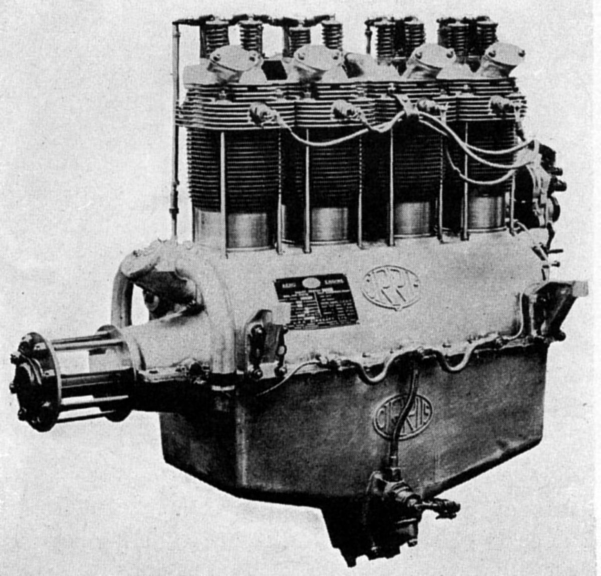
The Cirrus Hermes (Mark I) was a larger four-cylinder engine designed to be interchangeable with the Mark II and Mark III. With a 114 mm (4.488") bore, 140 mm (5.512") stroke, 5.716 l (348.8 in³) displacement and 5.1:1 compression ratio, its normal rating was 105 hp at 1,900 rpm and maximum rating 115 hp at 2,100 rpm from a 300 lb dry weight. It was 38.5" long, 17.97" wide and 36.06" high. Individual cylinders with heavily-ribbed cast-iron barrels were captured by aluminum heads held in place by four studs extending from the crankcase and passing through holes drilled in the fins. Aluminum-bronze valve seats were screwed and expanded into the cylinder heads in a valve arrangement similar to the Cirrus Mark III. The camshaft actuated the valves via tubular push rods and rocker arms that oscillated on special spindles that provided oil reservoirs for extended operation and were mounted on light steel brackets fastened to the cylinder head. The connecting rods were steel forgings machined all over, with the big end using a white-metal-lined phosphor-bronze bushing. The four-throw crankshaft was carried in five plain bearings, and a large ball thrust bearing at the front. The bearings were held to the upper crankcase by caps, the lower crankcase section acting only as an oil sump, but having a tray to retain the oil supply in the sump during aerobatics. The camshaft, which was driven by a train of spur gears at the engine's, was carried in the upper crankcase on five bronze bearings. The gear-type oil pump was located in the wet sump and driven through a worm gear attached to the front of an idler gear in the upper crankcase half. Oil was forced through a filter and an external pipe to the five main bearings and then through drilled holes to the crank-pins. Two magnetos, each fitted with an impulse coupling and arranged on either crankcase side forward side of the gear housing, provided dual ignition. A 42-mm Claudel-Hobson carburetor The supplied mixture that was routed through a steel induction manifold to each inlet valve port. Exhaust heat was applied to the induction manifold center to aid in vaporization and help prevent induction icing.
The Hermes Mark II was an improved Hermes Mark I with the same bore and stroke. Its normal rating was 110 hp at 2,000 rpm and its maximum 117.5 hp at 2200 rpm. It weighed 300 lb and its valve gear was enclosed by metal covers.
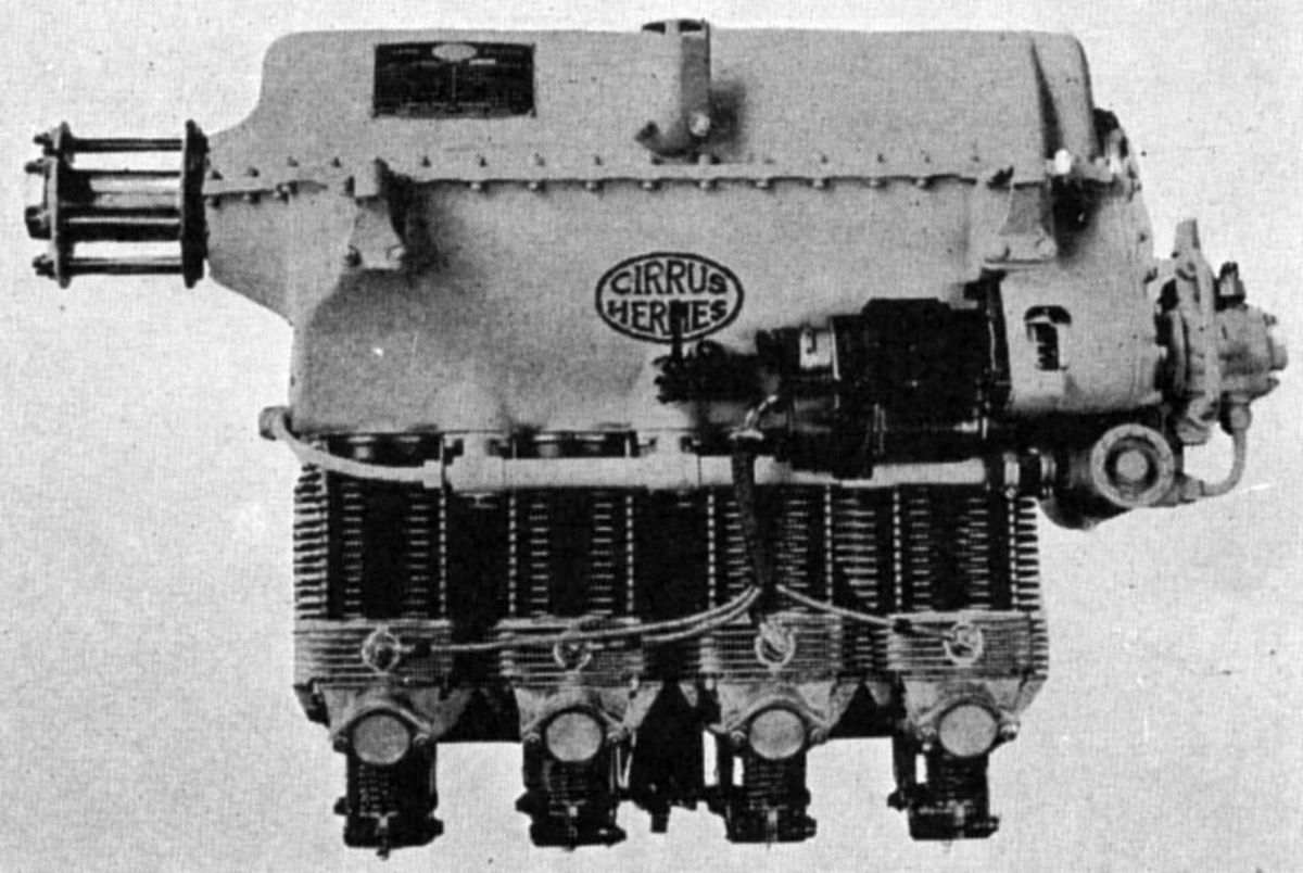 |
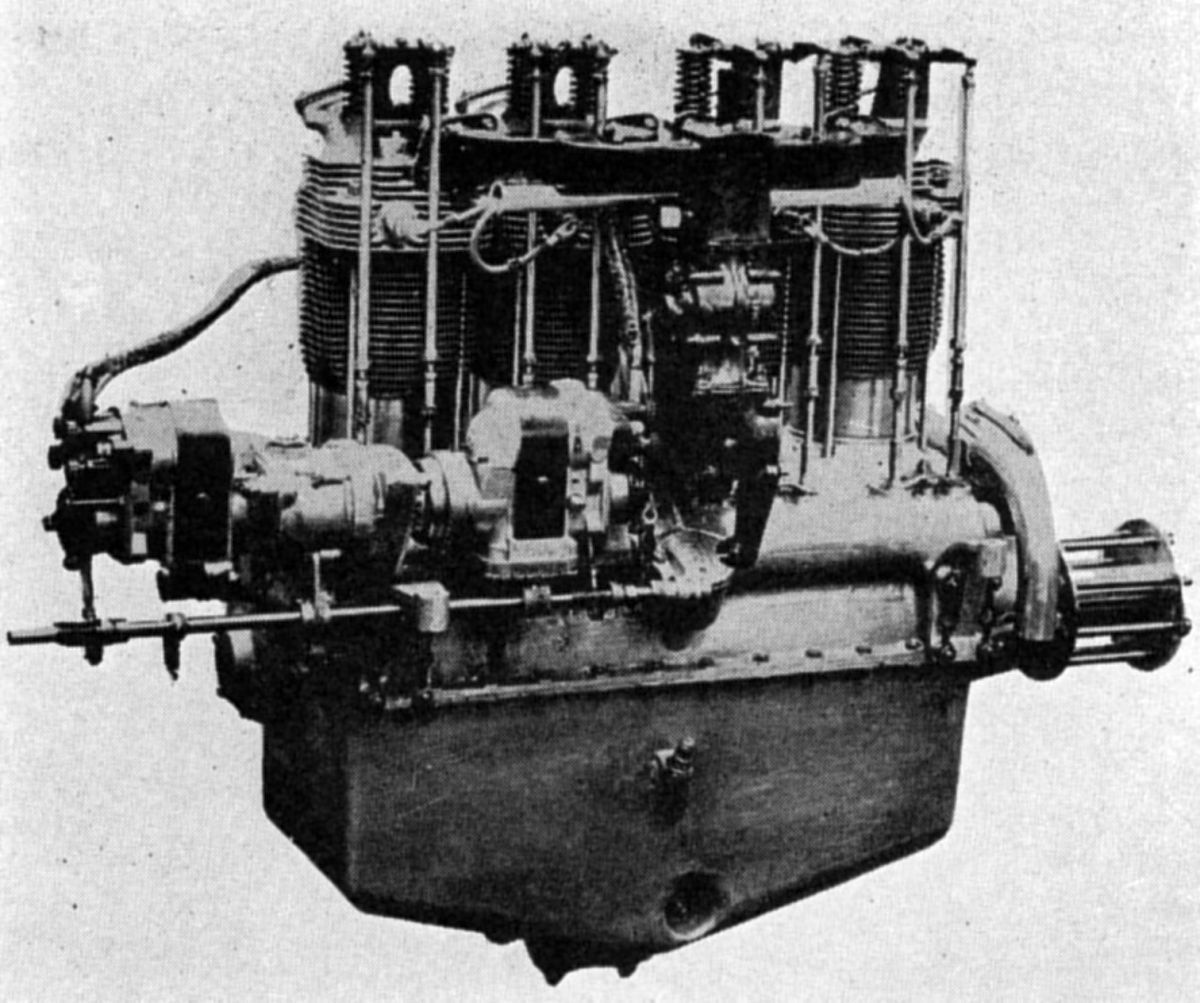
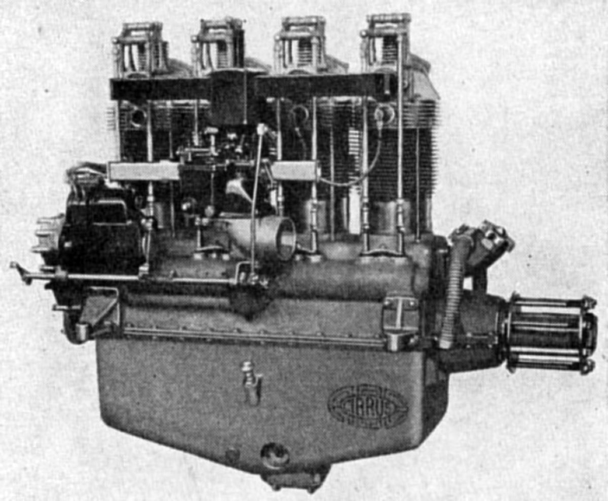
| Cirrus Hermes Mark IIB (A39) |
The Inverted Hermes Mark IIB was normally rated 105 hp at 1,900 rpm, and 115 hp at 2,000 rpm. It weighed 300 lb and in most respects was similar to the upright models. The cast aluminum-alloy crankcase lower portion housed the main bearings, and the timing gears were at the aft end. A dry-sump engine, the upper Elektron casting merely served as a cover. A pressure pump fed oil to the bearings under pressure and another pump scavenged the crankcase and returned the oil to the supply tank. Later engines of this series were fitted with enclosed valve gear, and resilient engine bearer feet were supplied as a part of the regular equipment. It was 42.4" long, 21.21" wide and 29.1" high.
The Hermes Mark IV, a further-improved version also arranged for inverted installation was rated 120 - 130 hp and weighed 300 lb.
Starting in 1935, Cirrus began producing the Major, followed by the Minor engine models before being taken over by Blackburn.
Clerget
Clerget, Blin and Cie, 37 Rue Cavé, Levallois, Paris built airplane engines from about 1911 until manufacturing rights were sold to Renault. Clerget is best known for the air-cooled rotaries it built and licensed during WWI. Gwynnes. Ltd., Hammersmith Iron Works, London, W. held British manufacturing rights for Clerget designs.
 |
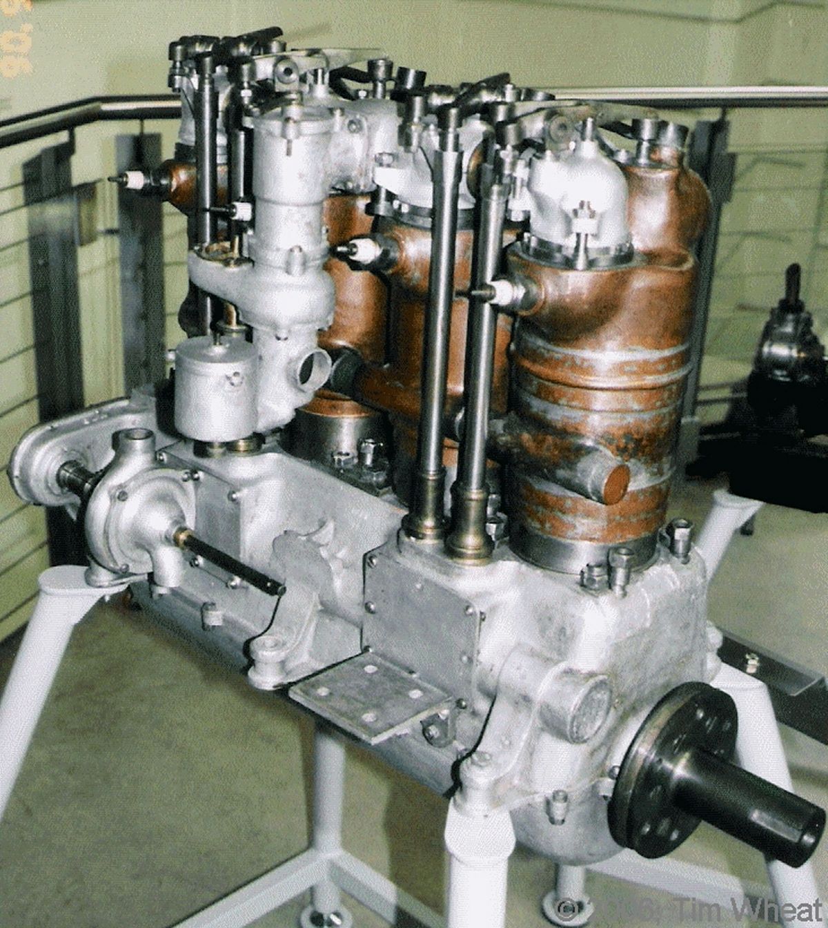 |
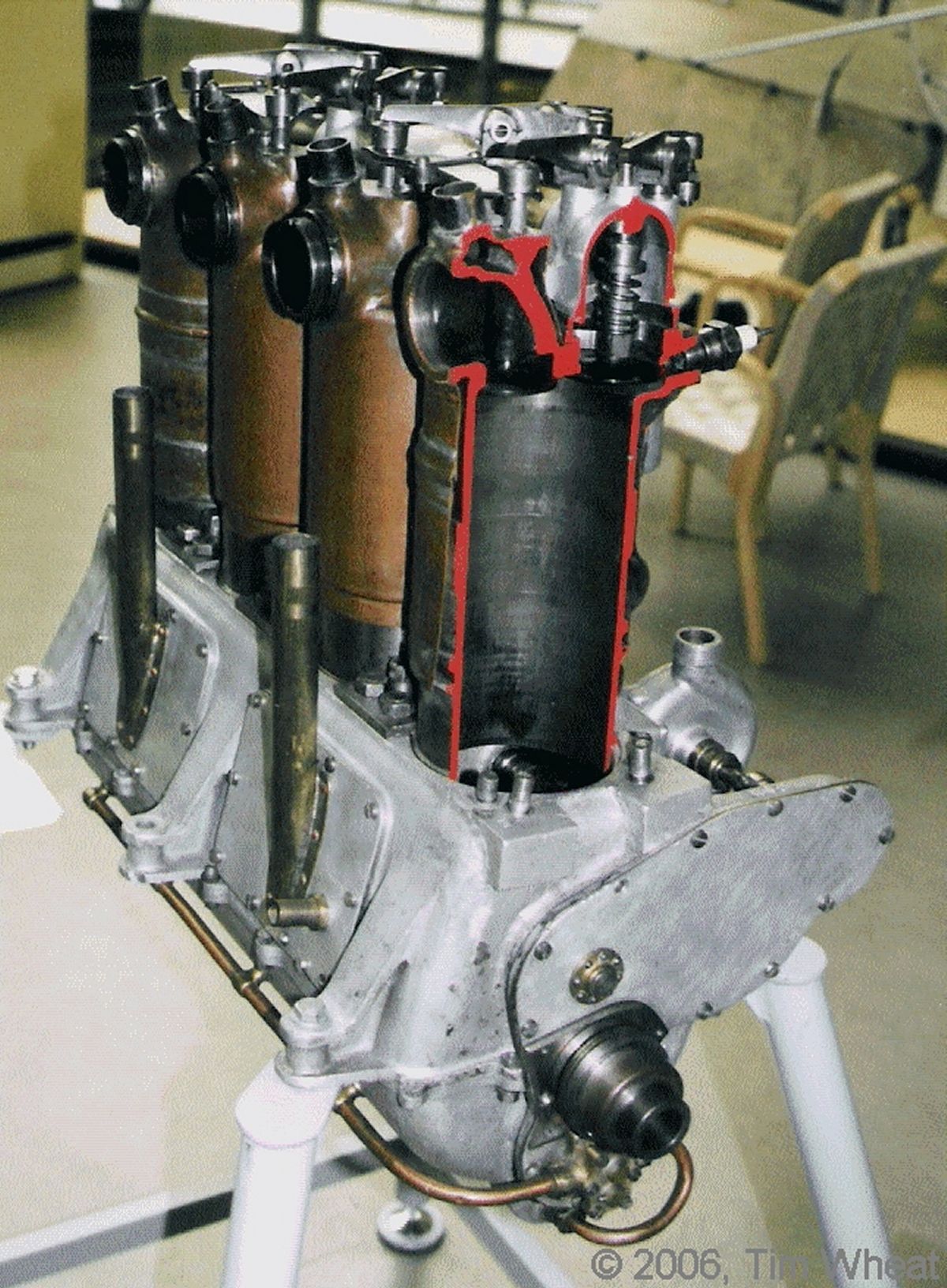
| Clerget 50 hp (Tim Wheat) | |
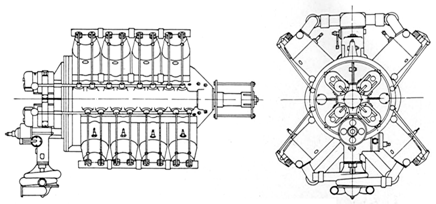
One of the earliest Clerget designs was a water-cooled four-cylinder in-line with a 110 mm (4.331") bore, 120 mm (4.721") stroke, and 4.562 l (278.4 in³) displacement that produced 50 hp at 1,450 rpm. The individual steel cylinders had expansion bellows in their electrolytically-deposited copper water jackets. Concentric valves were mechanically operated by push rods and rocker arms; the push rods actuating the inlet valve were inside the tubular rod that controlled the exhaust. Forced lubrication and magneto ignition were provided. A larger four-cylinder with a 140 mm (5.112") bore, 160 mm (6.299") stroke and 9.852 l (601.2 in³) displacement produced 100 hp at 1,250 rpm. A 90° V-8, the double form of the larger four-cylinder model, was rated 200 hp at 1,250 rpm and weighed 640 lb Two carburetors and two magnetos were used, and the camshaft, situated in the Vee, could be moved axially to change the valve timing.
Clerget built several air-cooled rotaries with seven, nine, and eleven cylinders. Their cylinders, machined with integral cooling fins from solid steel billets, were gripped between the two steel crankcase halves. The crankcase nose piece carried the propeller hub. 'I'he crankshaft was built up in sections, and the crankshaft aft end was attached to a flowing jet bloc tube type carburetor. Both the crankshaft and connecting rods ran on ball bearings. All connecting rods employed tubular shanks and the pistons were fitted with three piston rings and two obturator rings, both in the same groove, one inside the other. One inlet and one exhaust valve in each cylinder were operated through rocker arms, push rods and tappets from four-lobed inlet and exhaust cam rings rotating in the same direction as the engine at 9/8 engine speed. The rotating cam box had 18 internal gear teeth that drove the 16-tooth cam ring gears, which were eccentrically mounted; this was a distinctive Clerget design feature. Plunger pumps circulated the oil and ignition was furnished by high-tension magnetos. The high-tension current was taken to a carbon-brush located on the back plate that contacted a distributor whose sectors were connected by bare wires to the spark plugs.
Clerget 9-Cylinder Assembly Animation
The Type 7Y had seven cylinders and produced 60 hp at 1,200 rpm. Its bore and stroke was 120 mm (4.724"), resulting in a 9.5 l (579.7 in³) displacement. Fuel consumption was 0.63 lb/hp/hr and the weight was 198 lb, or 3.3 lb/ hp
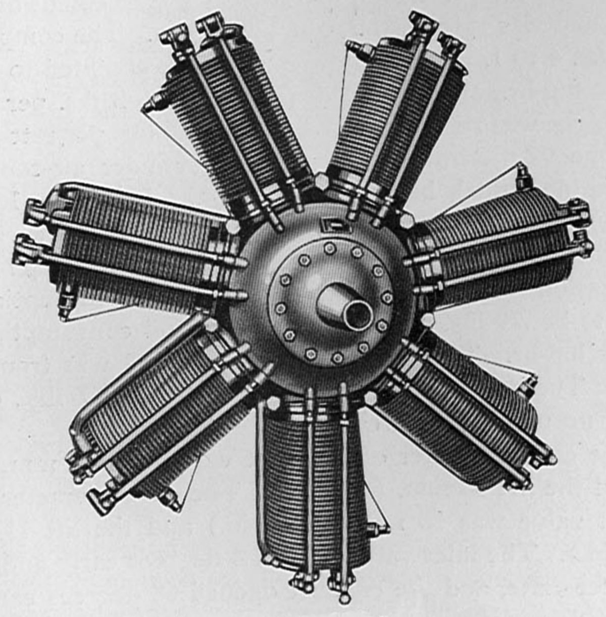 |
| Type 7Z (AEE) |
The Clerget Type 7Z, commonly known as the 80-hp model, was a larger seven-cylinder rotary that produced 85 hp at 1200 rpm. With a 120 mm (4.724") bore, 150 mm (5.905") stroke, 11.875 l (724.6 in³) displacement and 4:1 compression ratio, its fuel consumption was 0.665 lb/hp/hr oil consumption was 0.12 lb/hp/hr. Inlet valves opened at top center and closed 50° late and exhaust valves opened 68° early and closed 0° – 5° late. Weight was 216 lb, or 2.7 lb/hp. Its diameter was 36.25" and length 32". A nine-cylinder version using Type 7Z cylinders displaced 15.268 l (931.7 in³), produced 110 hp at 1,200 rpm and weighed 395 lb, or 3.6 lb/hp. Its fuel consumption 0.675 lb/hp/hr and its oil consumption was 0.168 lb/hp/hr.
The Clerget Type 9Z was an air-cooled nine-cylinder rotary with a 120 mm (4.724") bore, 160 mm (6.299") stroke, 16.286 l (993.8 in³) displacement and 4.36:1 compression ratio that developed 121 hp at 1,200 rpm and 123 hp at 1,300 rpm. Fuel consumption was 0.79 lb/hp/hr and oil consumption 0.146 lb/hp/hr. Dry weight was 367 lb, or 3.03 lb/hp. Its inlet valve clear diameter was 40 mm (1.575") and lift 10 mm (0.394"). The exhaust valve clear diameter 50 mm (1.969") and the lift 11.5 mm (0.453"). The inlet valve opened 4° early and closed 56° late; the exhaust opened 68° early and closed 4° late.
The Clerget Type 9B, built in both France and England, superseded the Type 9Z. It retained the nine air-cooled cylinders, 120 mm (4.724") bore, 160 mm (6.299") stroke and 16.286 l (993.8 in³) displacement. With a 4:1 compression ratio it produced 130 – 135 hp at 1,250 rpm. Fuel consumption was 0.665 lb/hp/hr and oil consumption ranged from 0.096 to 0.168 lb/hp/hr. Weight was 381 lb. English model valve timing was identical to the 9Z, while with French-built engines' inlet valves opened at top center and closed 52° late while its exhaust valves opened 64° early and closed at top center.
 |
 |
 |
 |
| Clerget Type 9B (NARA, AEE) | |||
The Type 9F was a French-built nine-cylinder with a new type of cam that, together with the longer stroke and higher compression, gave more power than the 9B. The Type 9F with a 120 mm (4.724") bore, 170 mm (6.693") stroke, 18.304 l (1,055.9 in³) displacement and 6.3:1compression ratio produced 197 – 202 hp at 1,300 – 1,350 rpm. Weight was 374 lb, or 1.87 lb/hp, and overall diameter was 40.2".
The English-built Type 9BF had a 120 mm (4.724") bore, 172 mm (6.772") stroke, and a 17.507 l (1,068.3 in³) displacement. With a 5.1:1 compression ratio it produced 146 hp at 1,250 rpm. With a 5.3:1 CR, it produced 153 hp at 1,250 rpm. Fuel consumption was 0.656 lb/hp/hr and oil consumption 0.156 lb/hp/hr.
A smaller, English-built Type 9J nine-cylinder developed 100 hp at 1,300 rpm from a 105 mm (4.134") bore, 140 mm (5.112") stroke, 10.910 l (665.8 in³) displacement and 5.1:1 compression ratio. Fuel consumption was 0.63 lb/hp/hr and oil consumption 0.156 lb/hp/hr. Weight was 250 lb, or 2.5 lb/hp. Cylinder construction departed from usual Clerget practice; the steel cylinder head was made separately, while the barrel was cast from aluminum with integral cooling fins and a steel liner.
 |
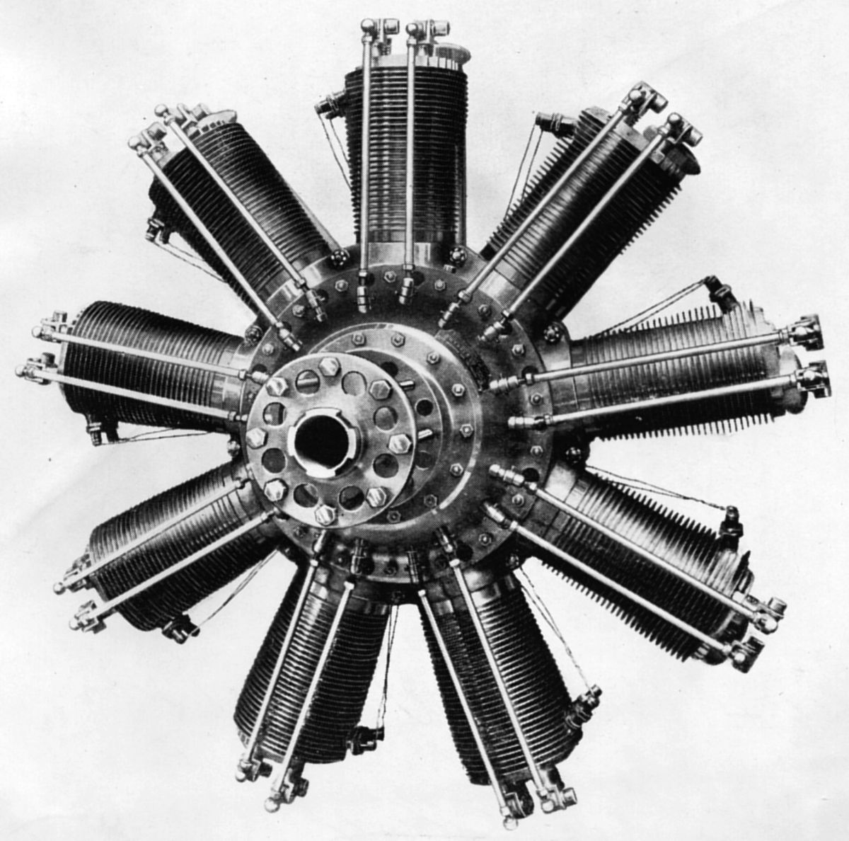
| Type 11EB (AEE) |
The Clerget Type 11EB was an air-cooled eleven-cylinder rotary built in both France and England. Using a 120 mm (4.724") bore, 190 mm (7.480") stroke, a 19.905 l (1,214.7 in³) displacement and 5:1 compression ratio, it produced 220 – 230 hp at 1,300 rpm, weighed 500 lb (2.5 lb/hp) and was 1,098 mm (43.23") in diameter. Fuel consumption was 0.63 lb/hp/hr and oil consumption was 0.132 lb/hp/hr.
The Type 11G, a French-built model similar to the Type 11EB engine except for a 5.7:1 compression ratio, was rated 250 hp at 1,300 rpm and 265 hp at 1,400 rpm Weight was 497 lb, or 1.99 lb/hp and the diameter 1,090 mm (42.9").
Clerget built an experimental eighteen-cylinder air-cooled rotary that developed 350 hp at 1,350. With a 1,029 mm (40.5") diameter and weighing 660 lb, it had a 120 mm (4.724") bore, 170 mm (6.693") stroke and 34.608 l (2,111.9 in³) displacement.
The Type 11A was an experimental variable-compression rotary with a 200 hp rated output.
 |
| Type X (AEE) |
The 1920 Clerget Type X was a water-cooled sixteen-cylinder X-type engine rated 400 hp. Its bore and stroke were 130 mm (5.118") its displacement was 27.608 l (1,684.7 in³). It produced 400 hp at 1,440 rpm and 420 hp at 1,600 rpm. Fuel consumption was 0.567 lb/hp/hr and oil consumption 0.06 lb/hp/hr. Dry weight was 770 1b, or 1.93 lb/hp. Its length was 52", width 39", and height 39".
 |
| Clerget Twin (AEE) |
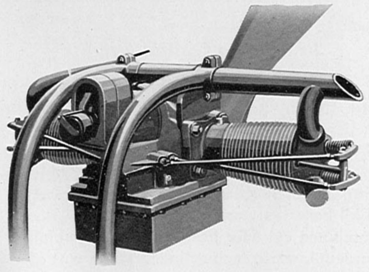
A two-cylinder air-cooled horizontally-opposed Clerget Twin, intended for small single-seatsport planes, was introduced in 1921. This engine, as well as a later model, were built by Renault after the Clerget-Blin firm was dissolved. The Twin was rated 10 – 16 hp. Its bore was 85 mm (3.347"), stroke was 100 mm (3.937"), and displacement 1.135 l (69.3 in³). It weighed 48.5 lb. The cylinders and their integral cooling fins were machined from steel forgings. The overhead valves were operated by push rods and rocker arms. Roller bearings were used for the crankshaft main and connecting rod big-end bearings. The pistons and crankcase were cast from aluminum alloy.
An improved Model 2A, introduced in 1923, produced 15 hp at 1,600 rpm and weighed 60 lb. Its bore was 85 mm (3.347"), its stroke 120 mm (4.724"), and its displacement 1.362 l (83.1 in³). The cylinder barrels were cast iron with integral cooling fins. The separate heads and barrels were held to the crankcase by means of four long studs. The carburetor featured altitude compensation, a high-tension magneto with variable spark advance furnished ignition, and the engine was pressure-lubricated.
Cosmos
Brazil-Straker Co., Ltd. of Fishponds, Bristol, England became known for its 15-hp Straker-Squire car before WWI. In 1914, Alfred Hubert Roy Fedden (6 Jun 1885 - 21 Nov 1973, later MBE, FRAeS) became the technical director due to his strong motor racing, technical and management skills. Late in 1914,the Royal Naval Air Service (RNAS) requested that Brazil-Straker undertake airplane engine repair and construction. The RNAS, which was using Curtiss JN-4 aircraft with Curtiss OX-5 engines to train its new pilots, was having a terrible time with the engines; they typically lasted only about five hours. Fedden found nearly all the OX-5s delivered to the RNAS were filty inside, poorly machined, poorly finished and suffered from engineering shortcomings. He improved quality control, the crankcase, valve lifters, induction and ignition systems. The revised engines now ran for 200 hours between overhauls. Based on this experience, Brazil-Straker began manufacturing Rolls-Royce engines and parts. With the exception of experimental engines built by the Rolls-Royce, Brazil-Straker manufactured all of the 75-hp Rolls-Royce Hawk models, as well as the Series I 190-hp Falcon V-12. Brazil-Straker also manufactured the 50 hp Renault 8Ca engine and parts for Rolls-Royce Eagle engines. Brazil-Straker was the only company whose quality standards were high enough to build Rolls-Royce engines and parts under license.
Early in 1917, the Air Board drew up specifications and asked Brazil-Straker to design an air-cooled fixed radial. Fedden and his small team worked practically around the clock to design what was to become the Cosmos Mercury. The prototype was running in just 5.5 months. His team then turned out the larger Jupiter design with equal dispatch. In 1918, the Cosmos Engineering Co. bought the Brazil-Straker aircraft engine business, which, still under Fedden's leadership, began manufacturing the world's first large air-cooled radials. In 1920, the Cosmos Engineering Co. failed and the Bristol Aeroplane Company took over its assets, continuing to manufacture the Cosmos engine line.
 |
 |
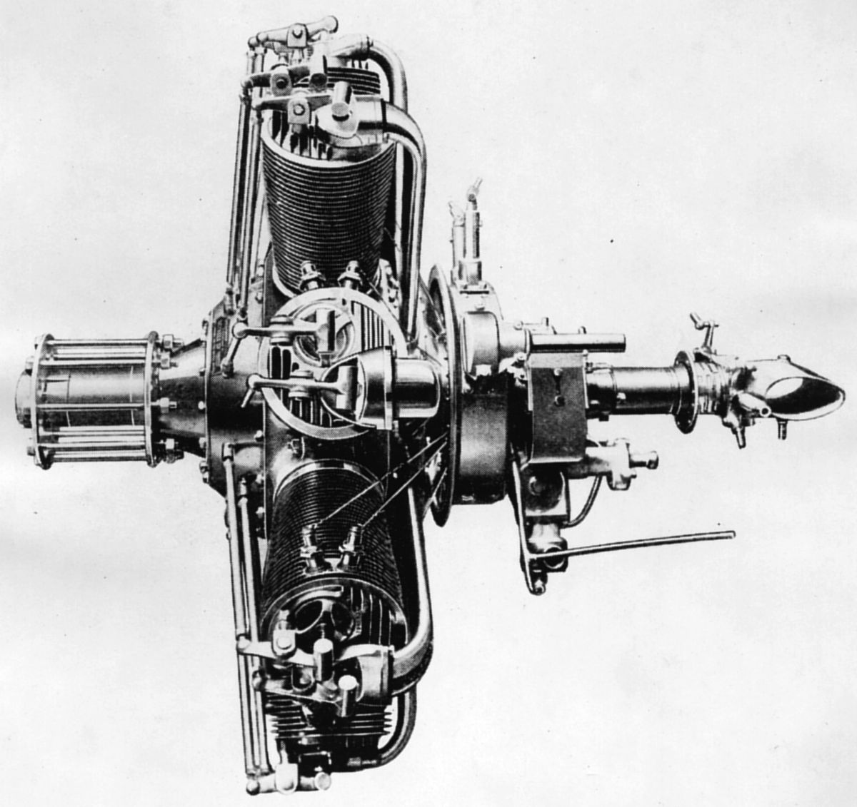
| Mercury (A39, Flt) |
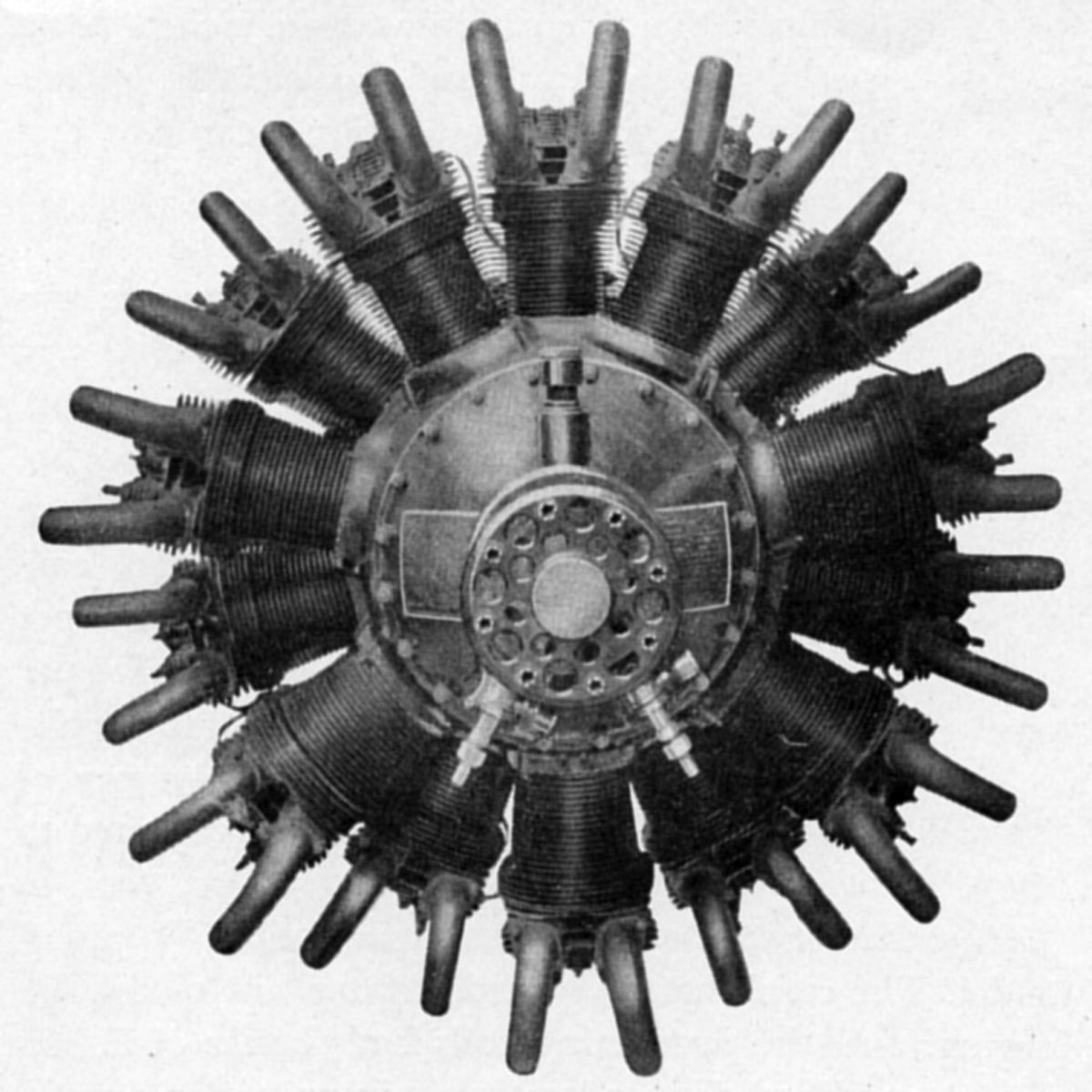
The Cosmos Mercury engine was designed by Fedden in 1917. It was a 14-cylinder air-cooled double-row direct-drive radial with a 4.375" bore, 5.8125" stroke, 1,223.3 in³ displacement and 5:1 compression ratio. It was rated 315 hp at 1,800 rpm and 347 hp at 2,000 rpm. Fuel consumption was 0.544 lb/hp/hr and oil consumption 0.09 lb/hp/hr. Two Ware duplex carburetors supplied a circular induction manifold with s separate duct to each cylinder. Gear-type pressure and scavenge pumps circulated oil within the dry-sump lubrication system. One inlet and two exhaust valves were situated vertically in each cylinder. The two-throw crankshaft was fitted with roller hearings throughout. Seven individual thin connecting rods were mounted side-by-side upon each crank-pin using separate roller bearings. Two M-L 7-cylinder magnetos in conjunction with a 14-cylinder Remy distributor provided ignition. Dry weight was 587 lb and the overall diameter was 41.625". The cylinders were machined from solid steel billets and featured circumferential cooling fins and a closed head-end upon which was bolted an aluminum cap (poultice) containing the valve ports and valve guides. It was hoped that this cylinder head scheme would distribute heat evenly enough to prevent warped valves, but the steel-to-aluminum interface never satisfactorily conducted heat away from the head.
 |
 |
 |
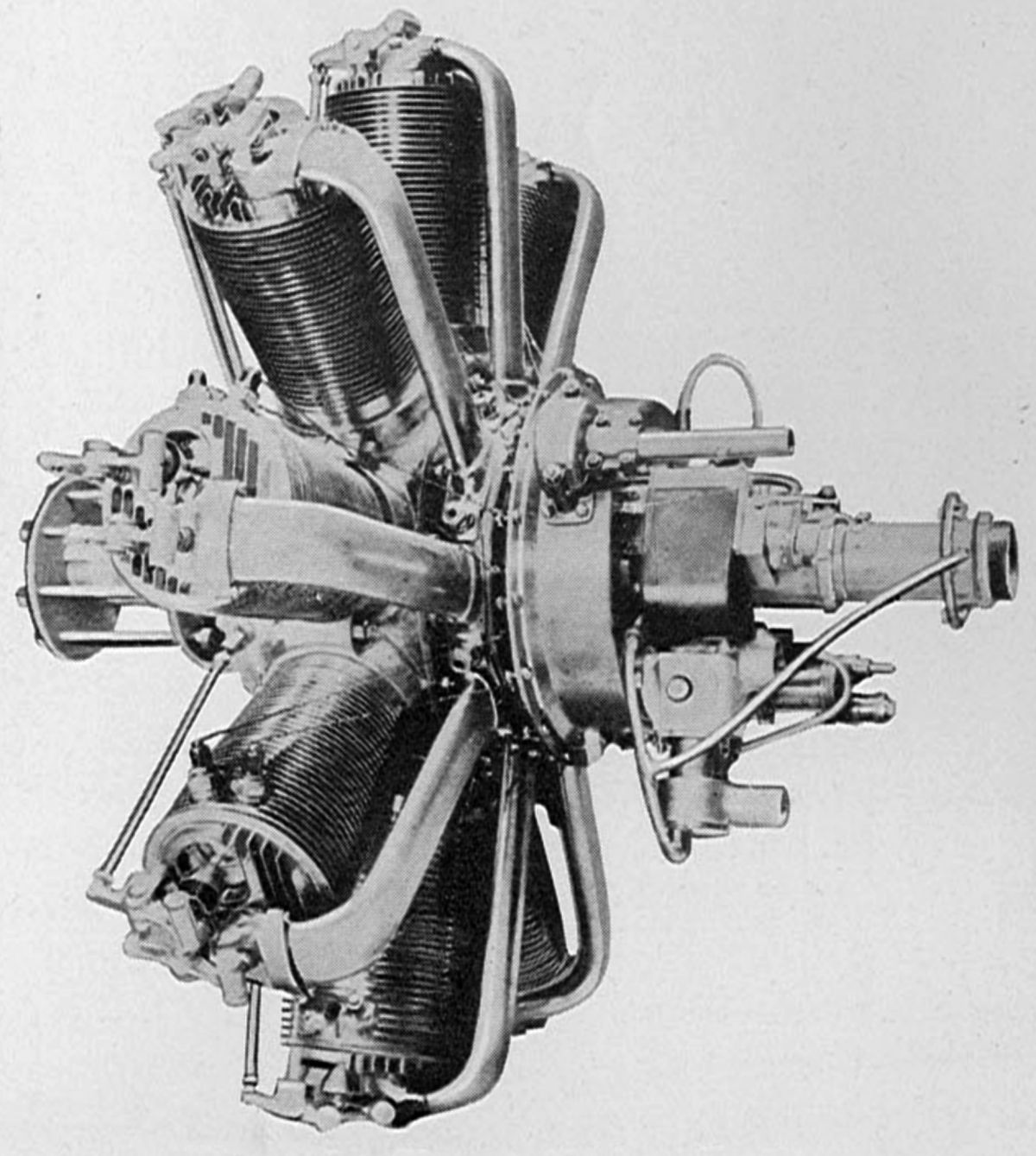
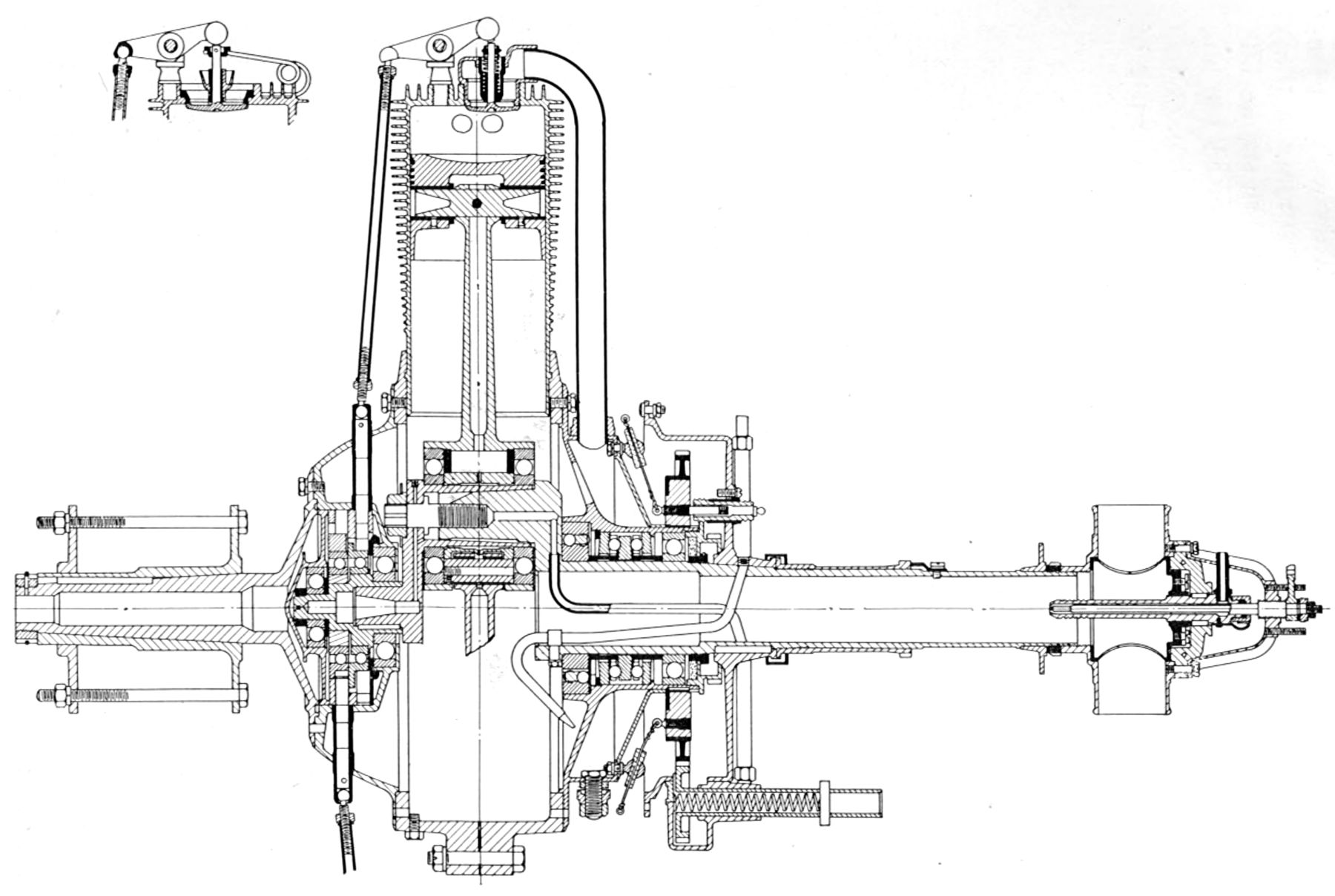
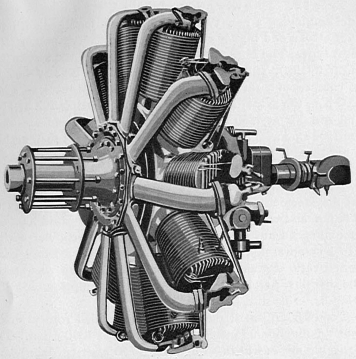
| Cosmos Jupiter I (NARA, AEE) | ||
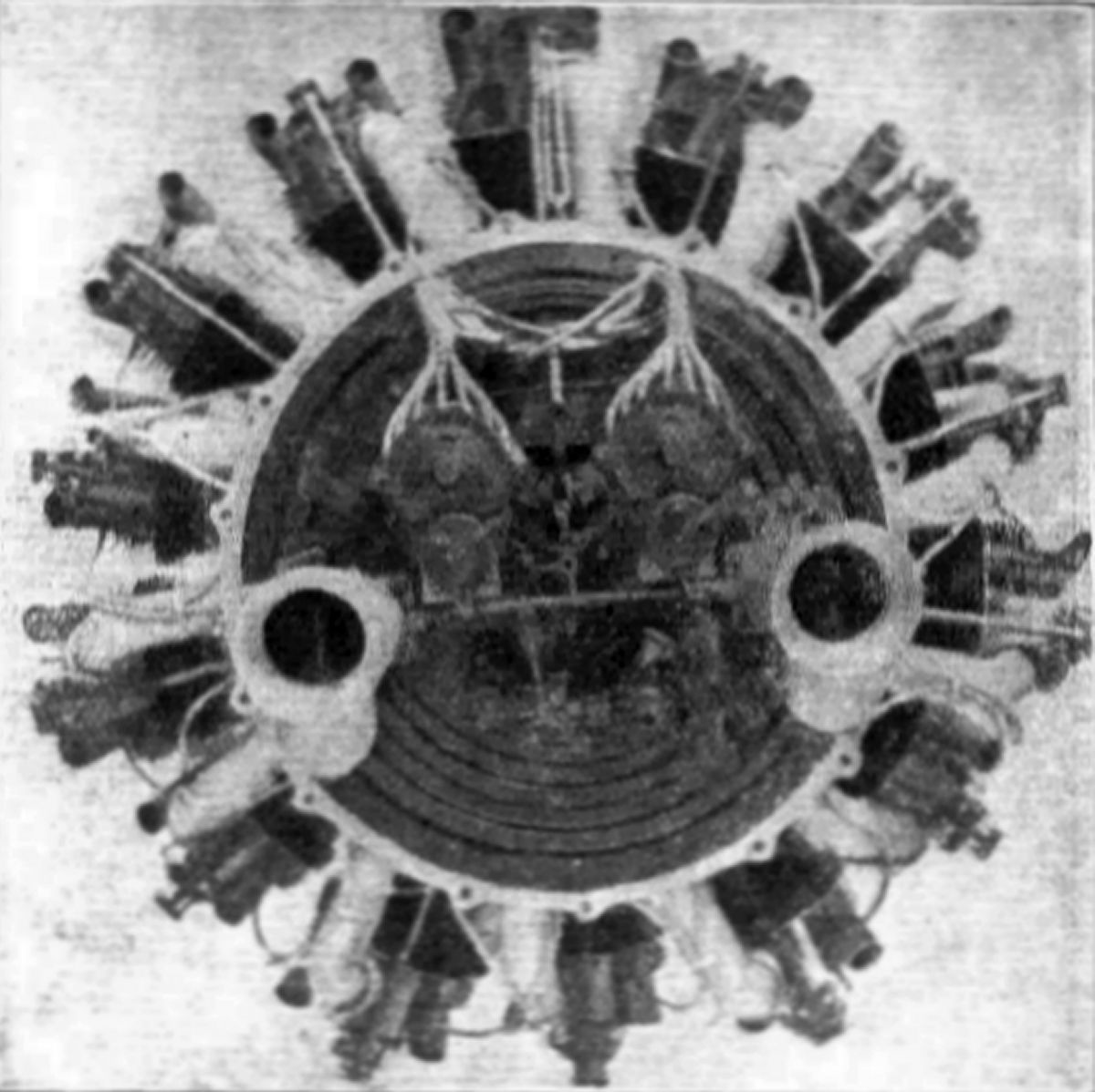
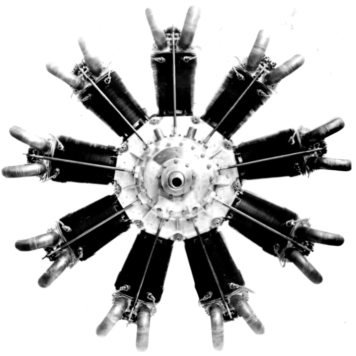
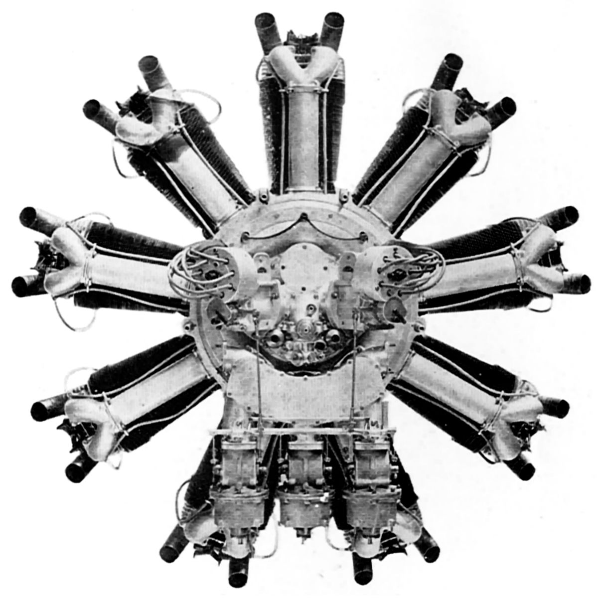
The Jupiter Series I was a 9-cylinder air-cooled direct drive radial with a 5.75" bore, 7.50" stroke, 1752.8 in³ displacement and 5:1 compression rated 400 hp at 1,640 rpm and 450 hp at 1,800 rpm. Fuel consumption was 0.557 lb/hp/hr and oil consumption 0.06 – 0.07 lb/hp/hr. Dry weight was 662 lb, outside diameter was 54.5" and the length was 32". Three Claudel H-C-8 carburetors with 44-mm venturis and 720-cc jets furnished the mixture to three spirals within the rear section; each spiral fed three cylinders. Gear-type pressure and scavenge pumps provided dry-sump lubrication. The cylinders were machined from solid steel billets, had integral circumferential cooling fins and a poultice head cap containing the valve ports and valve-guide bushings. This scheme continued to cause trouble with the Jupiter I. Two inlet valves with 1.875" clear diameter and two exhaust valves with 1.6875" clear diameter were fitted. The aluminum crankcase was split vertically in the cylinder plane. The single-throw one-piece K1-steel crankshaft was mounted on roller bearings. The master connecting rod, with its plain master bearing, was split at the big end and held together by four bolts; four link rods were hinged on either side of the split. All of the. rods were made with an H shank section. The aluminum pistons were fitted with three top rings, and dual ignition was furnished by two Thompson-Bennett 9-cylinder magnetos.
 |
| Jupiter II (AEE) |
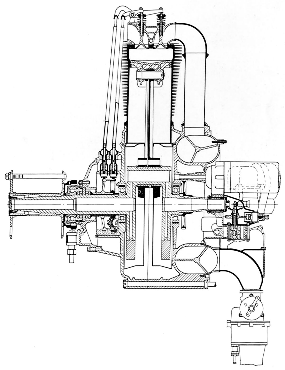
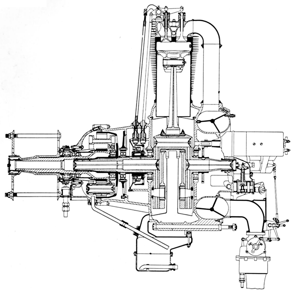
The Jupiter Series II had epicyclic propeller reduction gears with a 1:0.656 ratio. It was rated 450 hp at 1,850 rpm and 500 hp at 2,000 rpm. It weighed 800 lb and was 39.625" long. Except. for the reduction gear and connecting rod construction, the Series II design closely followed the Series I. The master rod big end had an outside bearing upon which was hinged a separate counterweight that guided itself in the main counterbalance and served to relieve the high centrifugal loads on the crank-pin bearing.
The Jupiter Series III was similar to the Series II, but had its normal propeller speed reduced to 660 rpm.
The Hercules was an 18-cylinder air-cooled radial engine with two rows of nine cylinders. Its bore was 6.25", stroke was 7.50", and the displacement was 4,141.7 in³. It was rated 1,000 hp at 1,750 rpm, and it was fitted with an epicyclic reduction gear to give the propeller a normal speed of 1,150 rpm. Weight was 1,400 lb. Cylinder construction was similar to other Jupiter models; there were four valves per cylinder, and the spiral induction manifold was employed. The counterweighted two-throw crankshaft was made in one piece and mounted on roller bearings. Dual ignition was furnished by a special Delco unit, and an electric starter with an epicyclic reduction gear was installed.
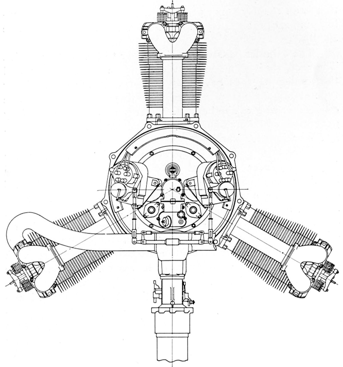 |
| Lucifer (AEE) |
The Lucifer was a three-cylinder air-cooled direct-drive radial with a 5.75" bore, 6.25" stroke and 486.9 in³ displacement rated 100 hp at 1,600 rpm. Fuel consumption was 0.557 lb/hp/hr and oil consumption 0.025 lb/hp/hr. Gear-type pressure and scavenging pumps provided dry-sump lubrication. Dry weight was reported 300 lb. Cylinder construction was similar to other Jupiter models. The crankshaft was made from a one-piece solid forging, and the connecting rods had H-section shanks. Aluminum modified slipper piston were fitted with three top rings and one oil-scraper ring at the bottom. Dual ignition was furnished by generators and distributors, and a hand crank was available for in-the-cockpit starting.
References
Angle, Glenn D, ed. Aerosphere 1939 (New York, New York: Aircraft Publications, 1940).
Anble, Glenn D, ed. Airplane Engine Encyclopedia (Dayton, Ohio: Otterbein Press, 1921).
“The Cosmos Aero Engines” Flight (3 Jul 1919, 869-871).
Gunston, Bill Fedden - the life of Sir Roy Fedden (Derby, England: The Rolls-Royce Heritage Trust, 1998).
Morse, William. Rotary Engines of World War One (Olney, England: Nelson & Saunders, 1987).
Nahum, Andrew. The Rotary Engine (London, England: Her Majesy's Stationary Office, 1987).
Image Sources: A39 = Aerosphere 1939; AEE = Airplane Engine Encyclopedia; Flt = Flight Magazine; NARA = U.S. National Archives and Records Administration; UKNA = United Kingdom National Archives.
Send mail to
![]() with questions or comments about this web site.
with questions or comments about this web site.
![]()