Selected Early Engines
Beardmore, Bentley, Benz,
BMW, Bristol, Bugatti
Compiled by Kimble D. McCutcheon
Published 1 May 2022
Bristol
The Bristol Aeroplane Company of Bristol, England acquired the Cosmos Engineering designs and patents when Cosmos was liquidated in 1920. Bristol also acquired the services of Roy Fedden, who had designed the Cosmos engines, as part of the deal. Development of Cosmos designs, particularly on the Jupiter, continued. Bristol granted design licenses to firms in France, Italy, Belgium, Germany, Portugal, Czechoslovakia, Spain, Yugoslavia, Poland, Switzerland, Hungary, Finland, Japan, Canada, and the U.S.A.
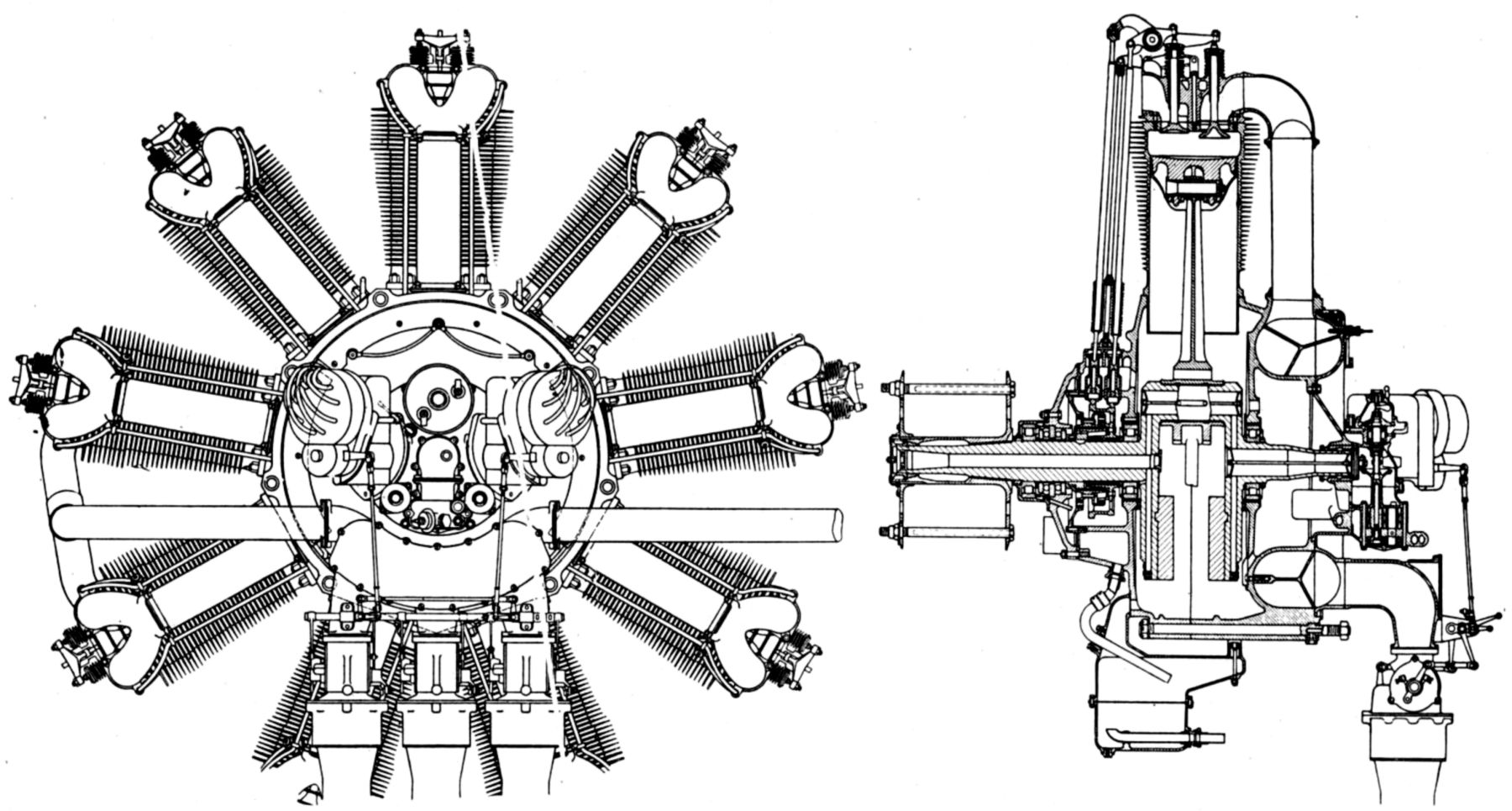
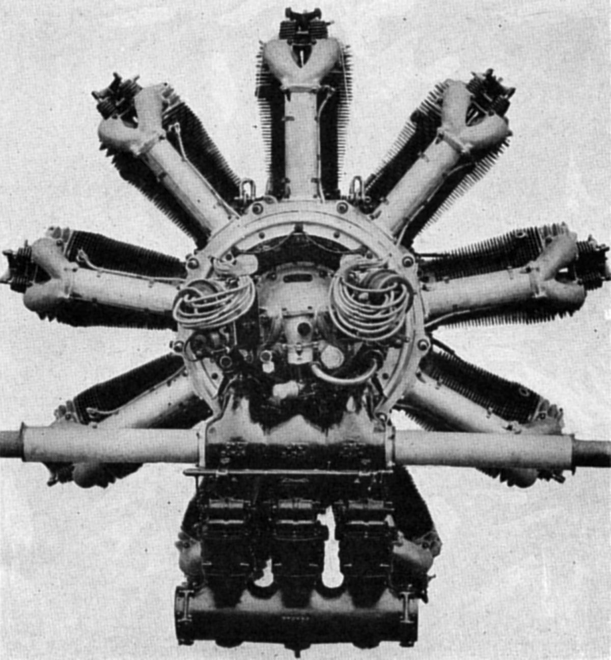
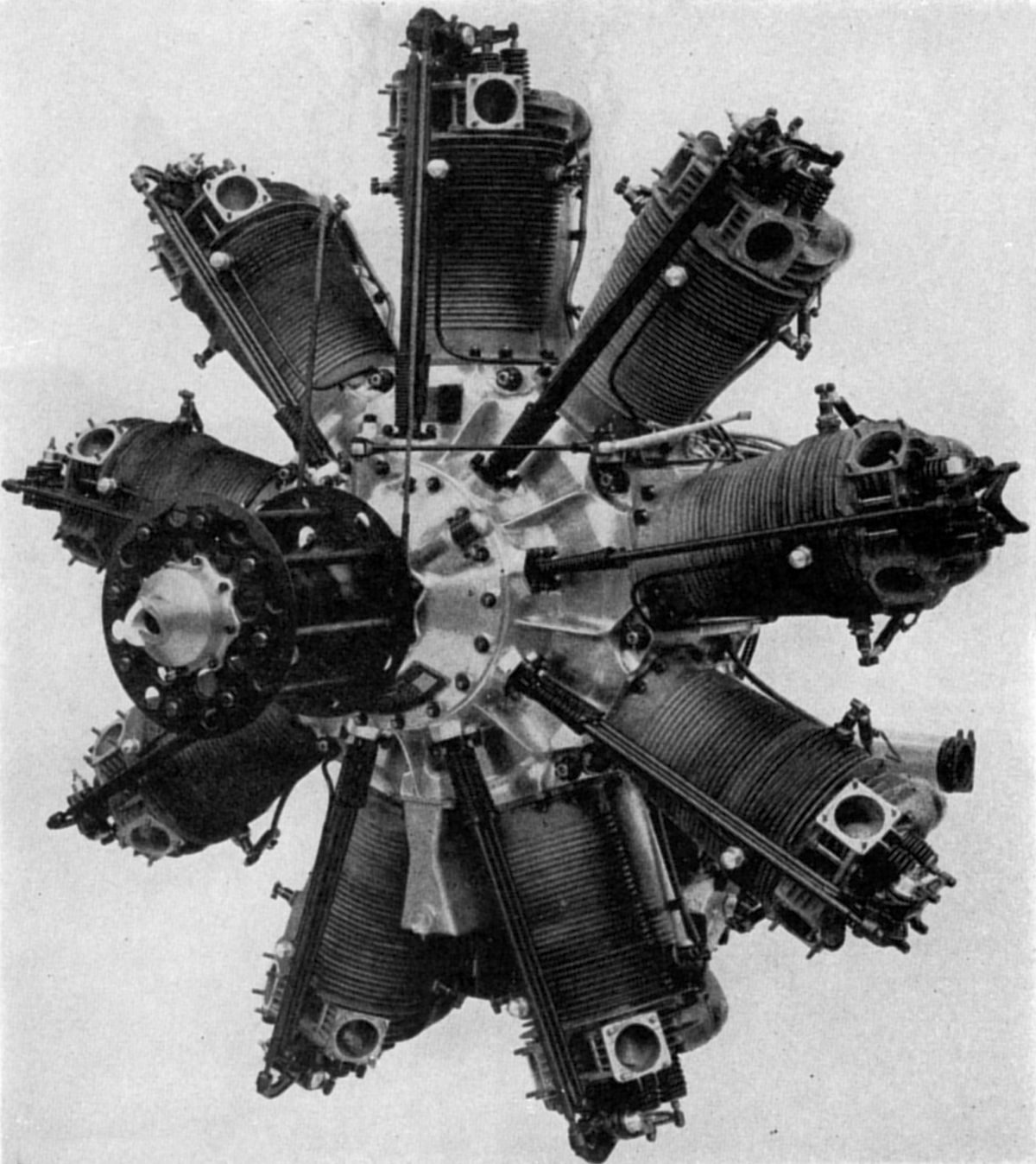
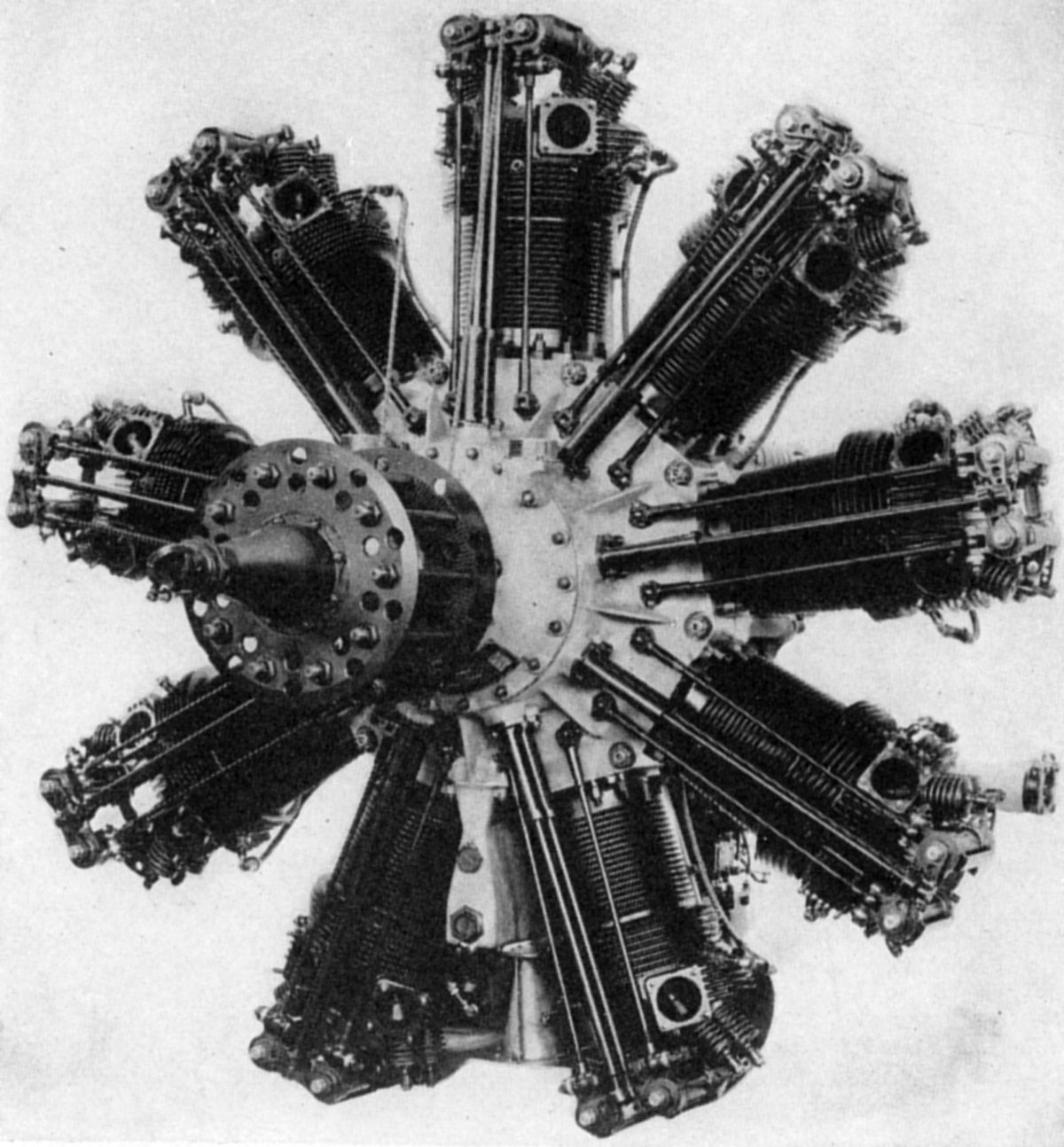
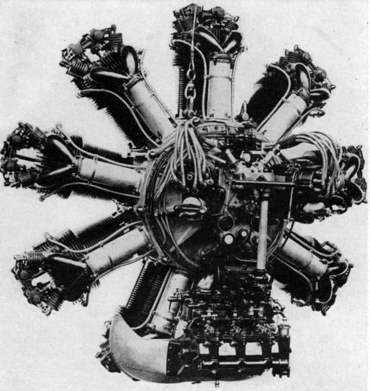
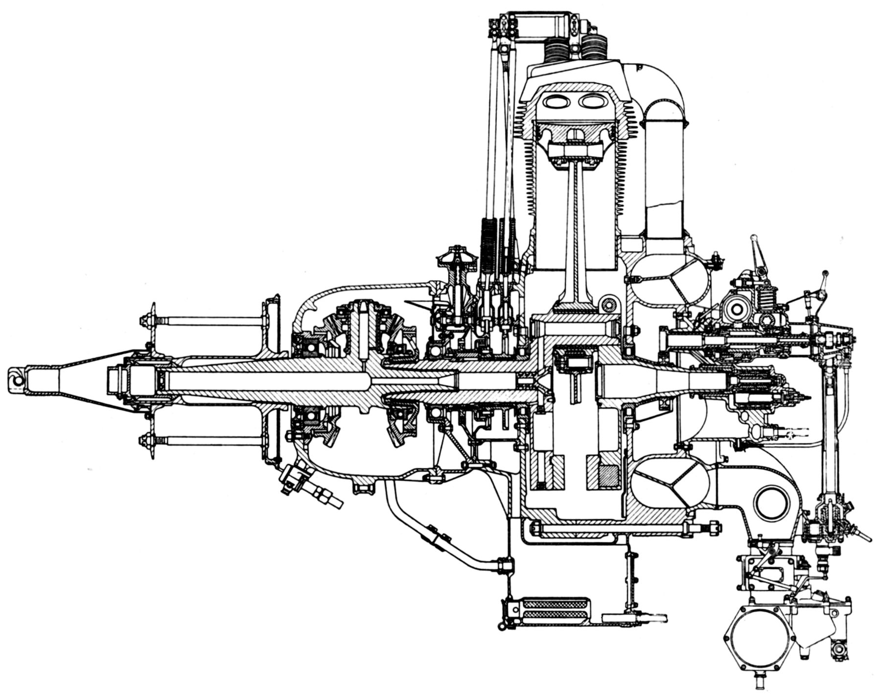
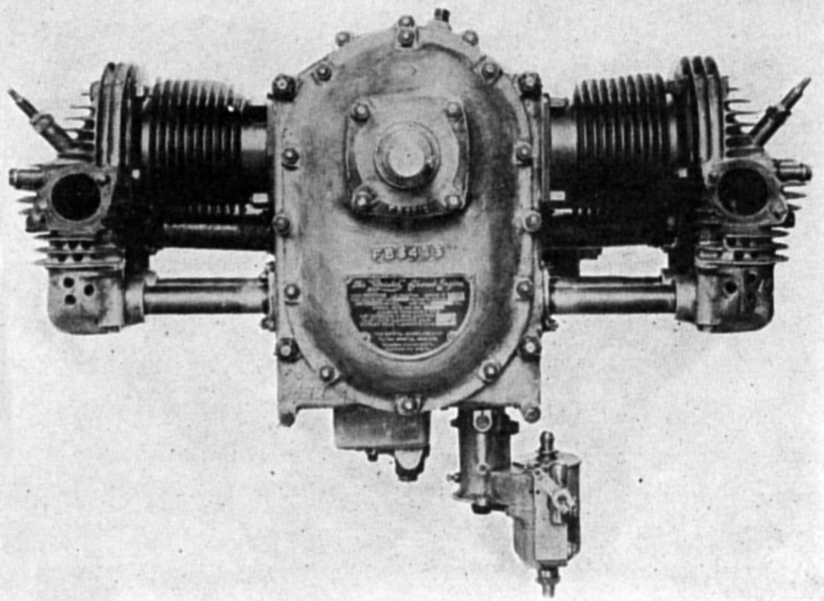
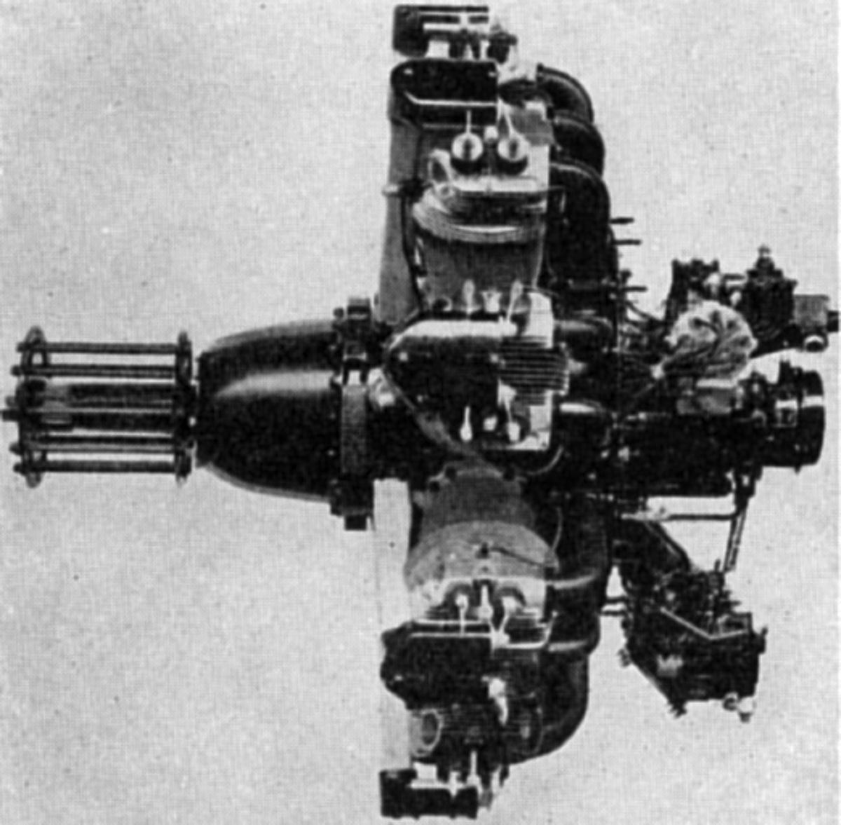
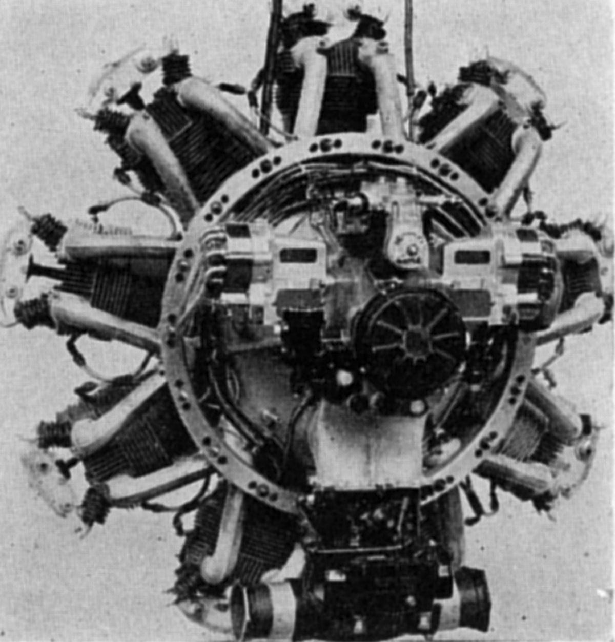
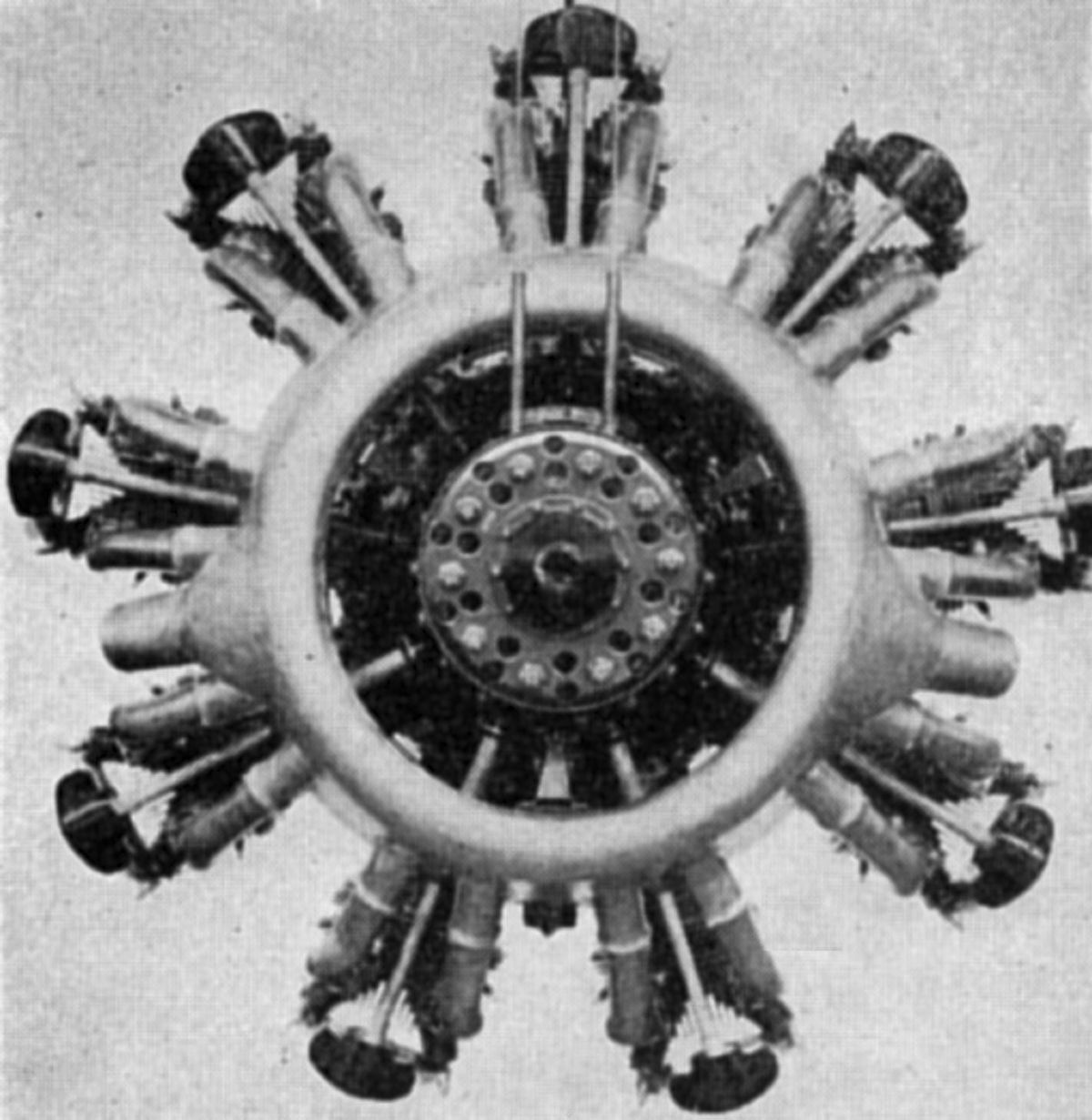
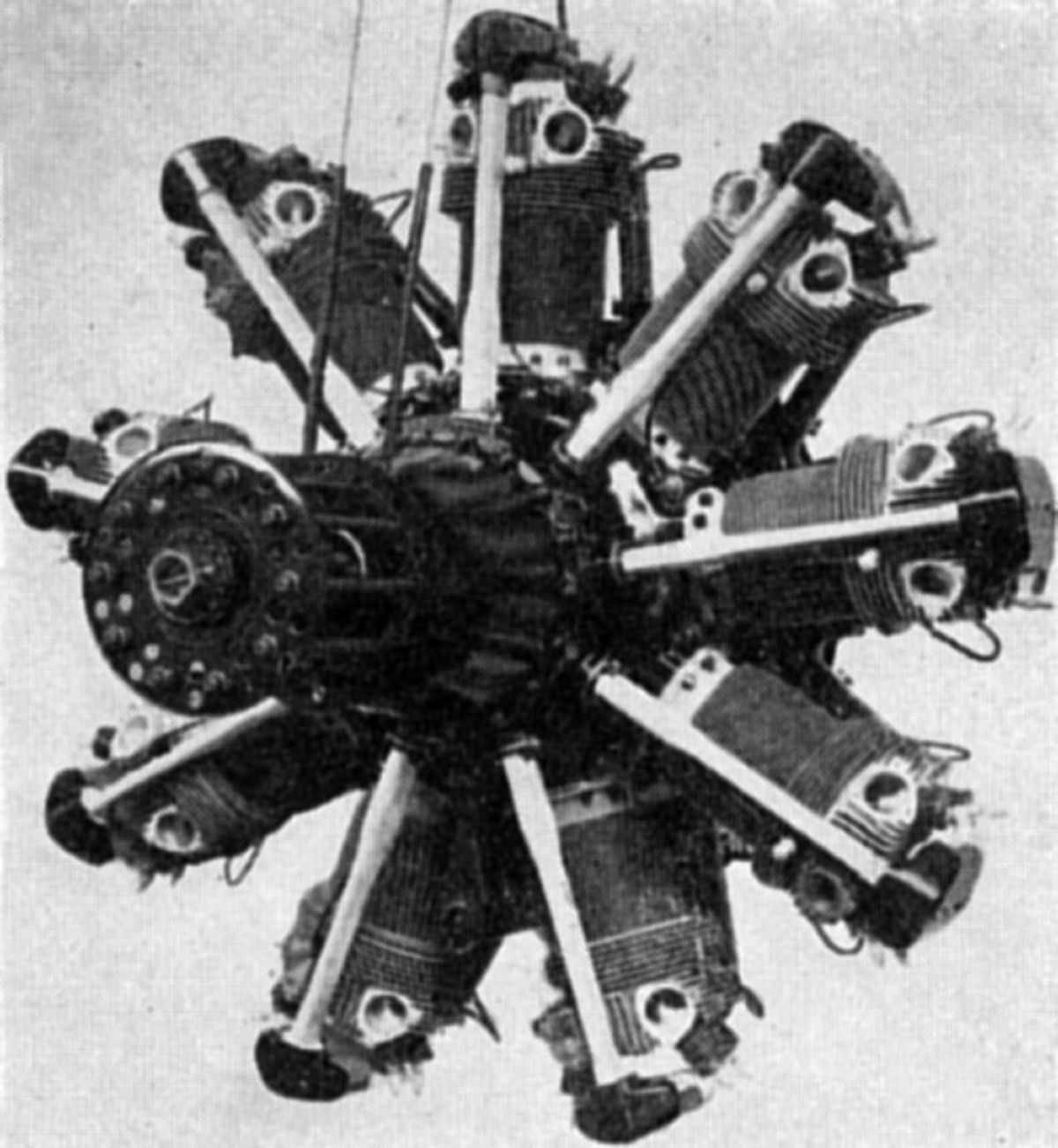
The Bristol Jupiter air-cooled nine-cylinder radial series, with its 5.75" bore, 7.50" stroke, and 1,752.8 in³ displacement followed the original Cosmos Jupiter design. All Jupiter engine models were similar, the principal variation among the several models being confined to rating, compression ratio, accessory, gearing and supercharger details. Cylinders were machined with integral cooling fins from closed-end steel forgings. An aluminum-alloy casting, containing the valve ports and stem guides, was bolted upon the cylinder with Invar packing used below the nuts on later engines to compensate for thermal expansion differences between steel and aluminum, creating a permanent joint with ineffective heat transfer. This construction is often called the poultice head. The barrel fins were eccentric on engines on Series VI and above, which gave a larger radiating surface at the cylinder back, Two inlet and two exhaust, seated in the cylinder head, were operated via forked rocker arms and tubular steel ball-ended push rods. The rocker arm bracket was hinged laterally to the cylinder head at its center line, and tied at its front end by a rod extending to the crankcase, thus balancing rocker assembly and cylinder movement due to expansion so as to maintain constant valve clearances.
Two crankcase sections were joined in the cylinder plane. Starting with the Jupiter V, the crankshaft also was made in two sections with the front section carrying the crankpin, which the rear web slipped onto. A key integral to the rear web entered a keyway in the crankpin and the joint was made tight by a clamp bolt that passed through the crank web split end. The key and keyway were later eliminated. The crankshaft ran on two roller bearings. Direct-drive engines had an additional front-mounted ball bearing to carry radial and thrust loads. Geared engines used a ball bearing at the propeller shaft front and a white-metal steady bearing that piloted in the crankshaft at the propeller shaft tail end. Slipper-type aluminum pistons were fitted with two compression rings and one oil-scraper ring. The piston pin floated in both rod and piston, and was secured endwise by spring rings. The master/slave connecting rod system used a split big end for early engine, but starting with the Series VI, the master rod had a solid-ring big end bearing employing a floating white-metal-lined phosphor-bronze bushing. The connecting rods had H-section shanks and were machined all over.
Claudel carburetors were used on Series III, IV, and V series engines, A Bristol Triplex carburetor, having three separate float chambers housed in a common casting, was fitted to all later Jupiter engines. The fuel-air mixture entered three ports in the annular induction chamber at the crankcase rear and a spiral distributor ring providing a separate passage from each carburetor throat to three cylinders of even spacing. Two B.T.H. magnetos provided dual ignition. The dry-sump lubrication system used gear-type pressure and scavenge pumps.
|
|
|
|
|
|
|
|
|
|
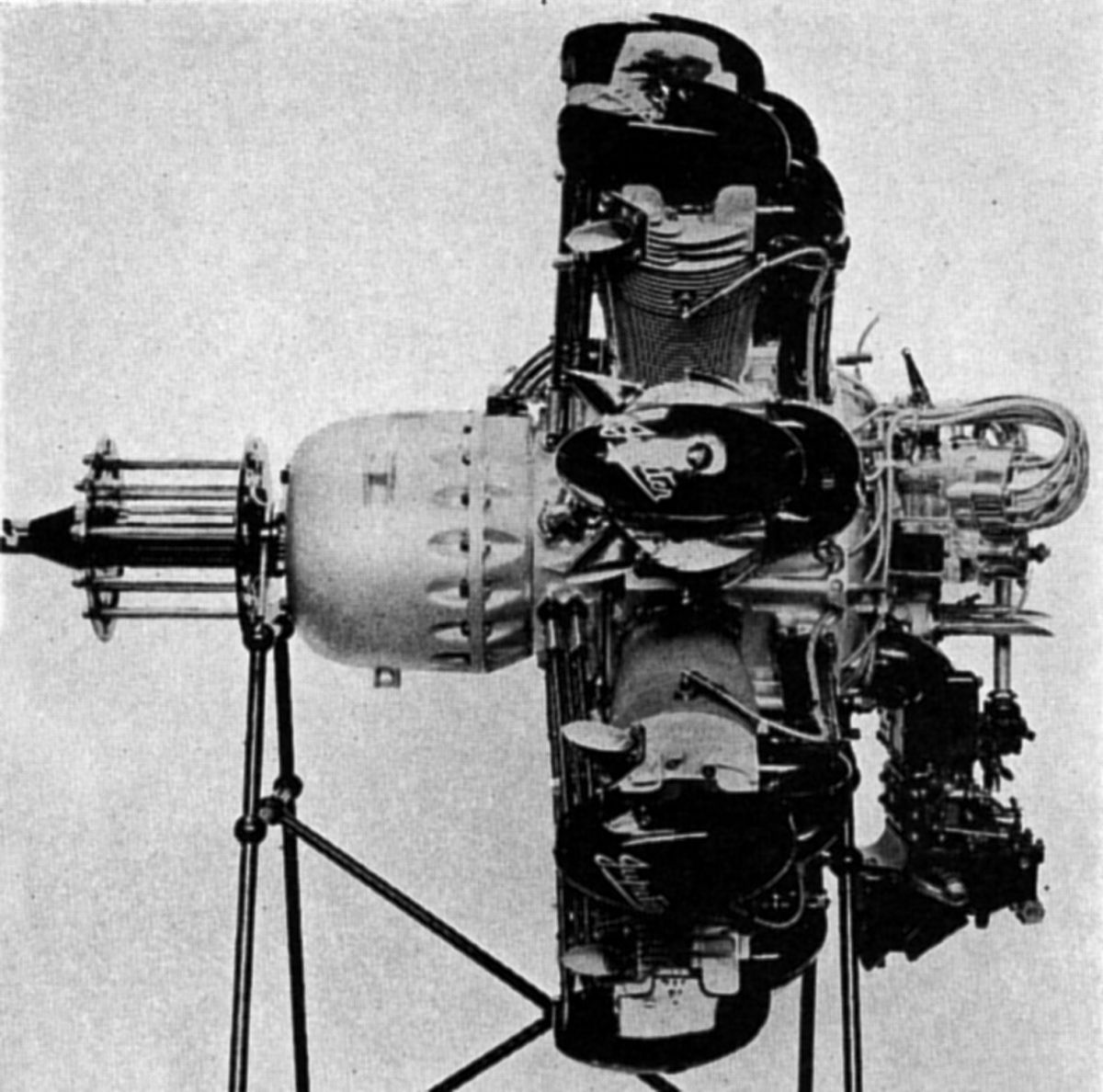
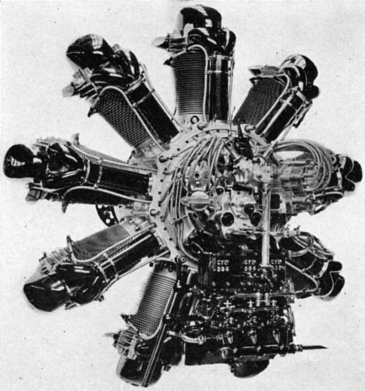
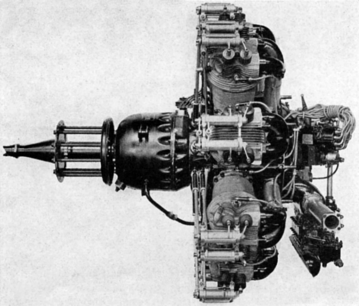
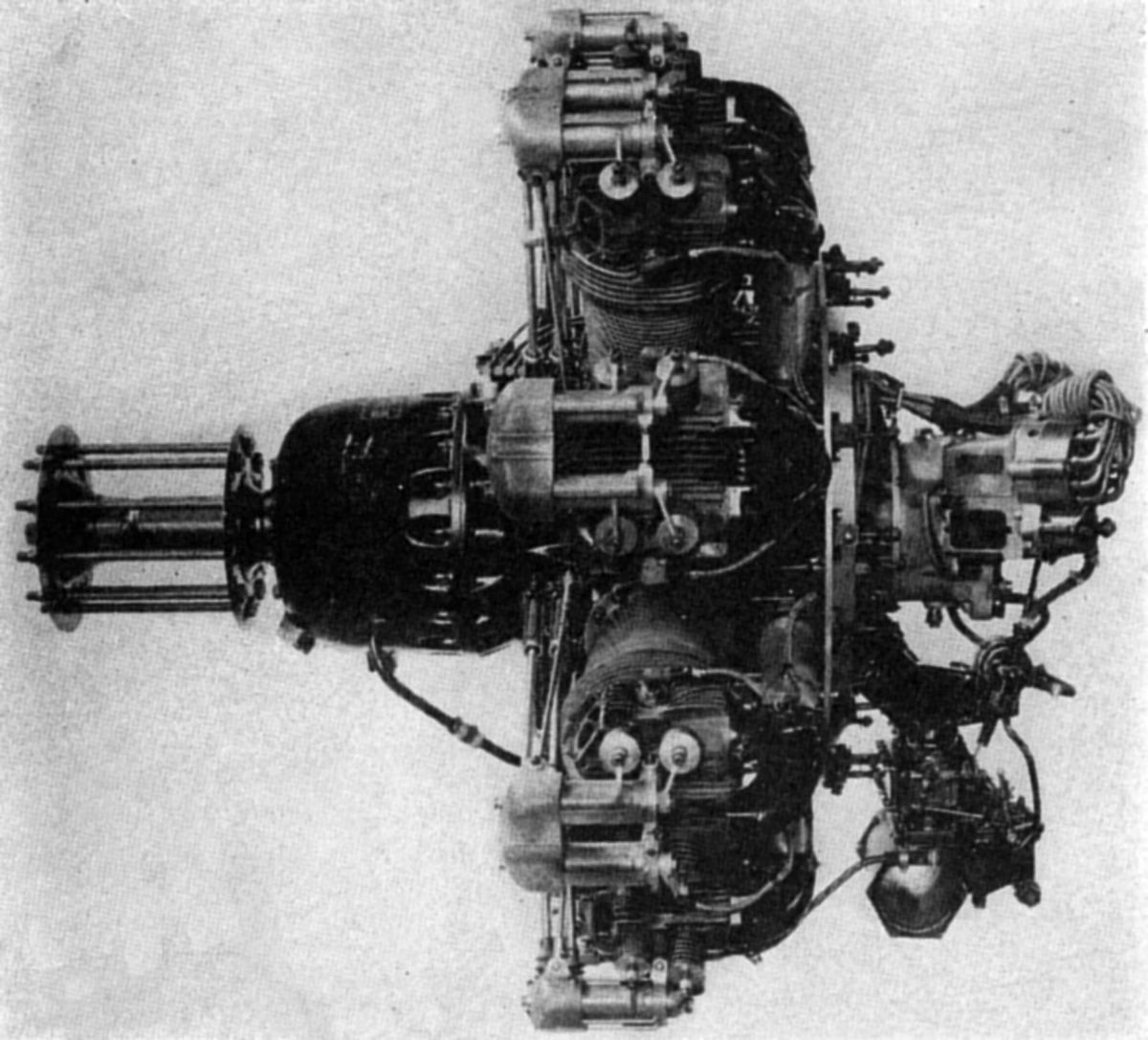
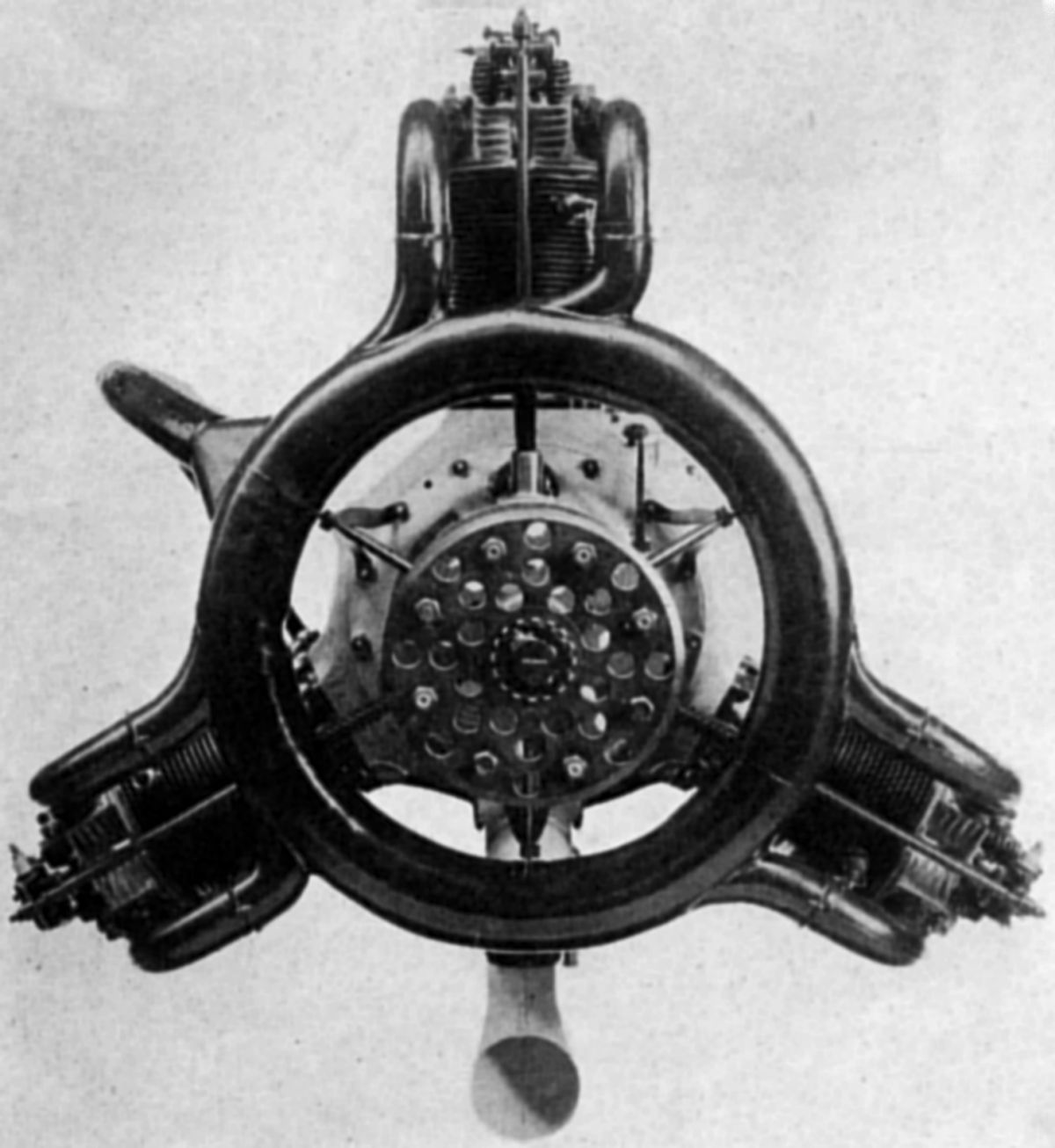
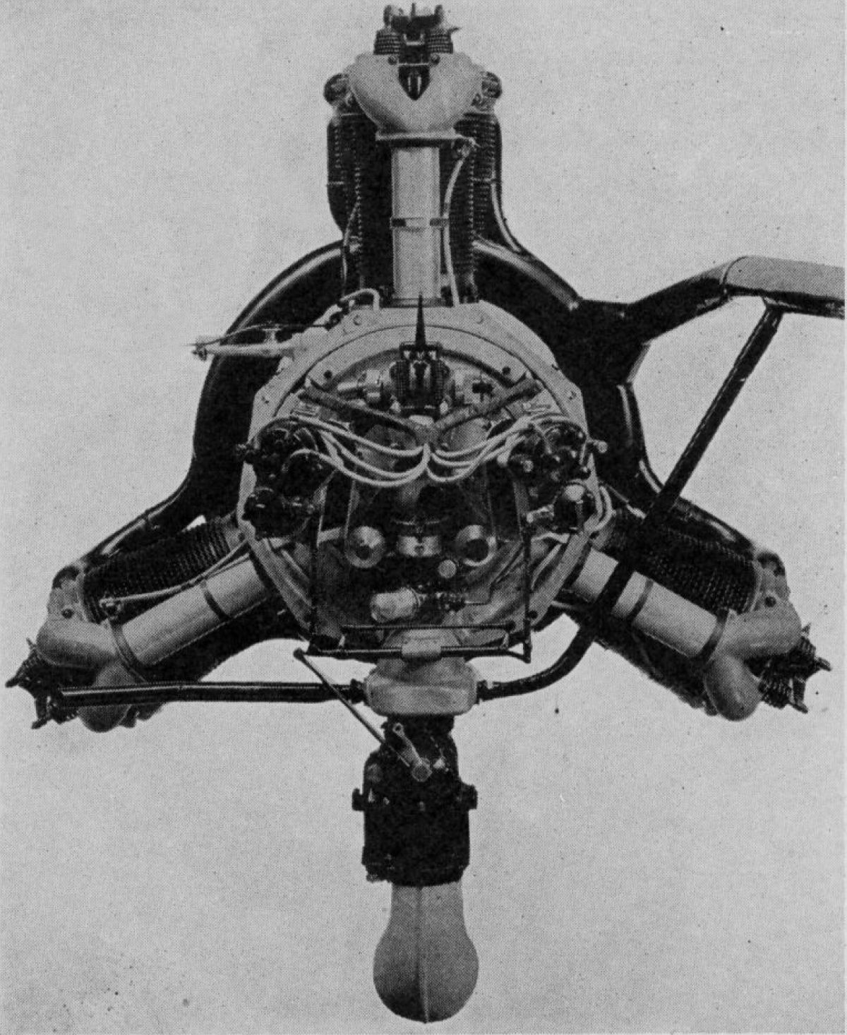
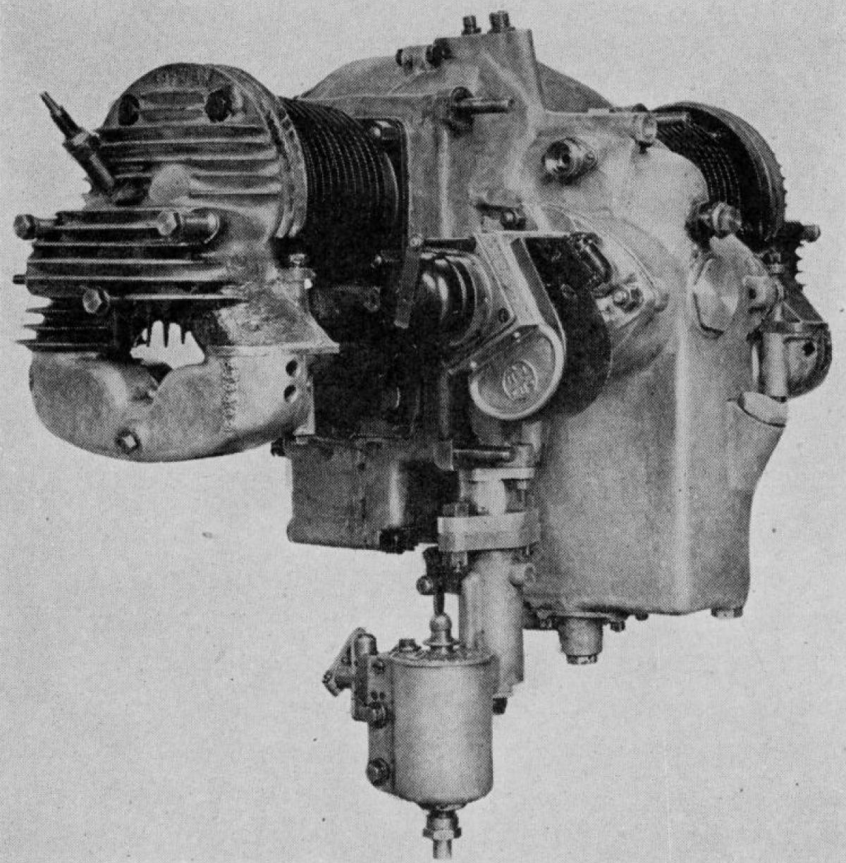
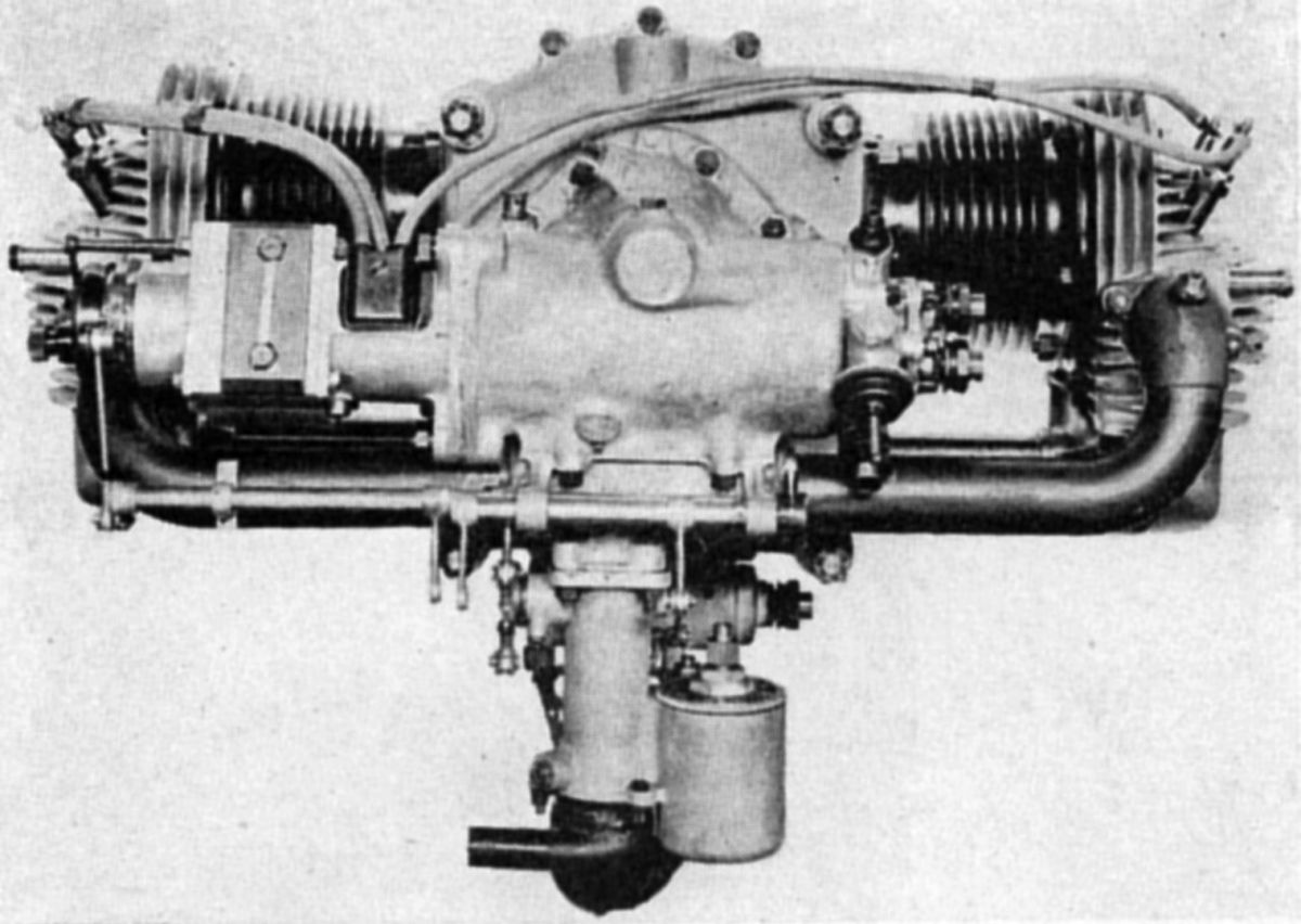
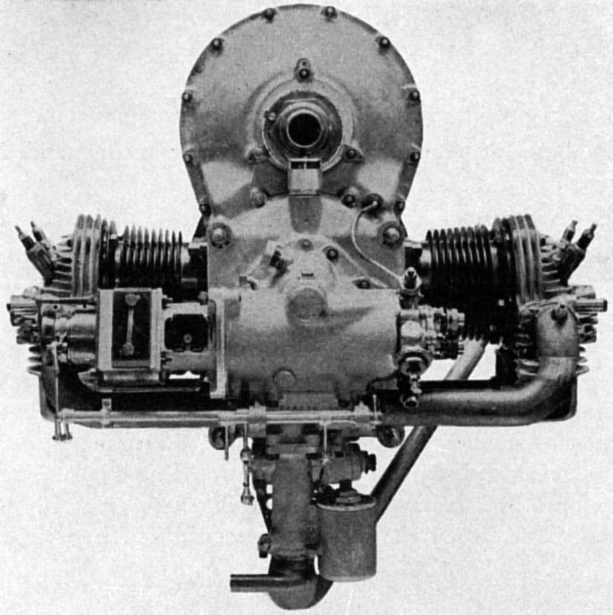
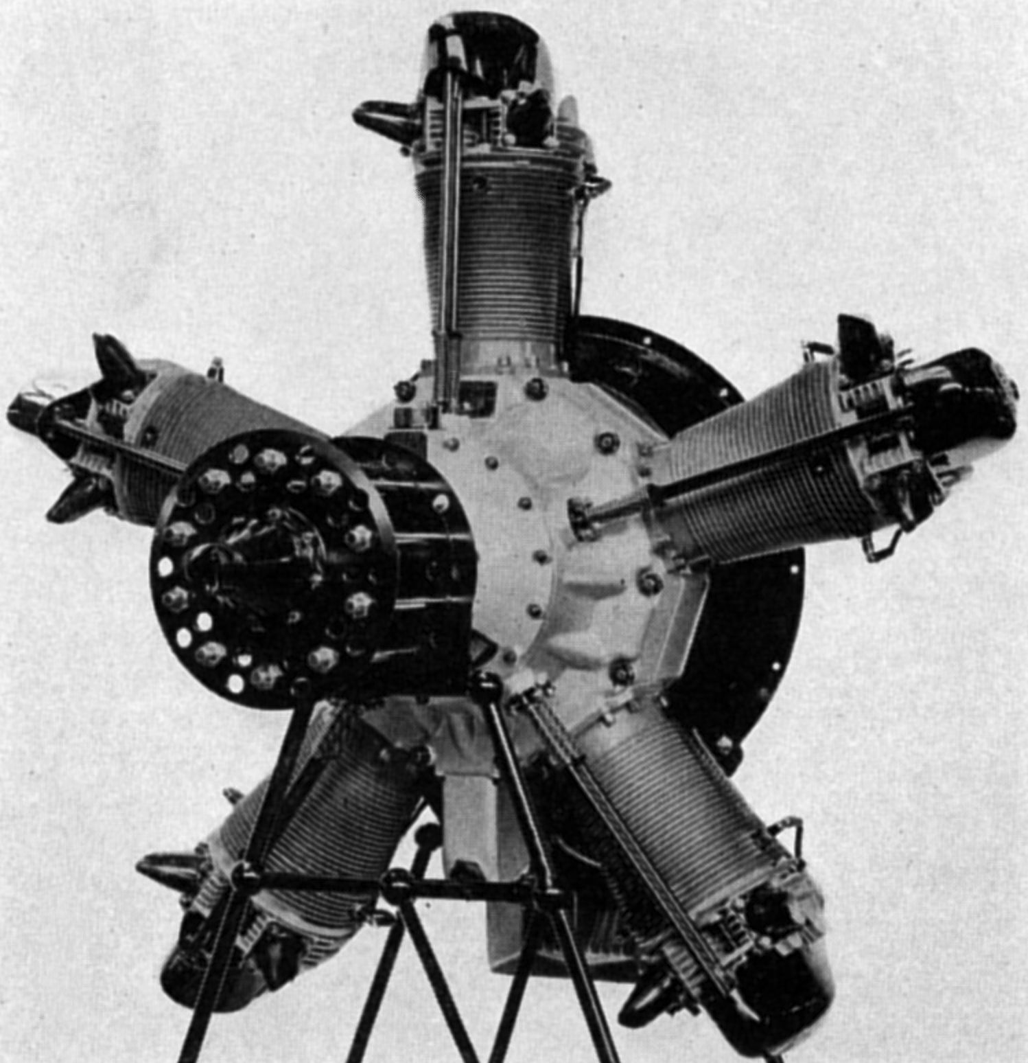
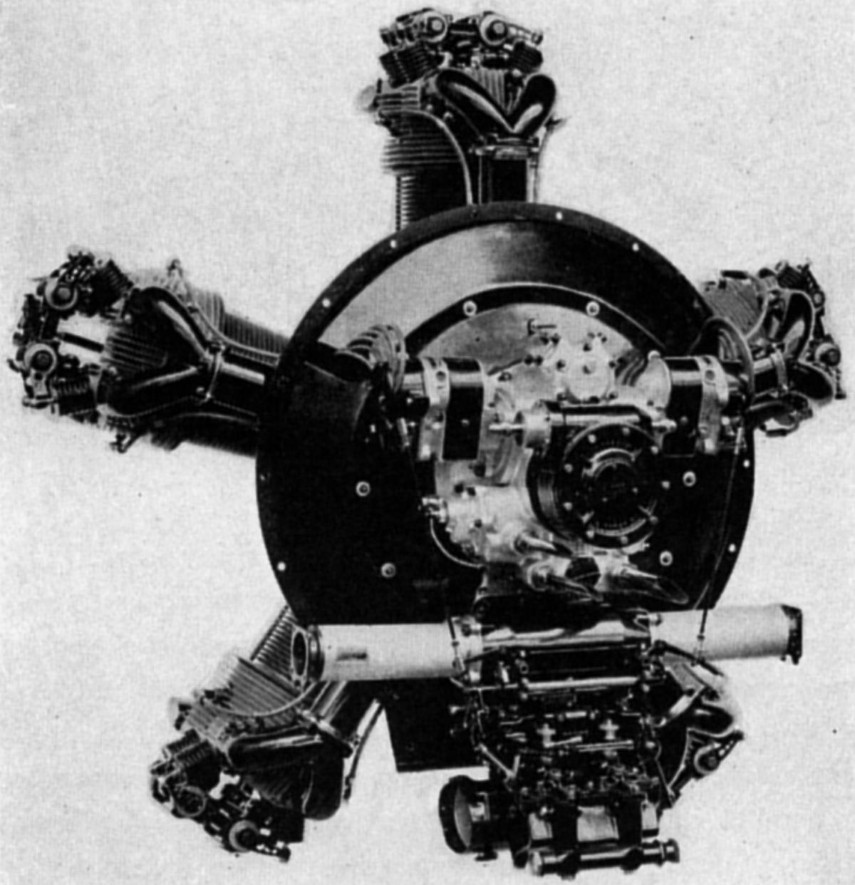
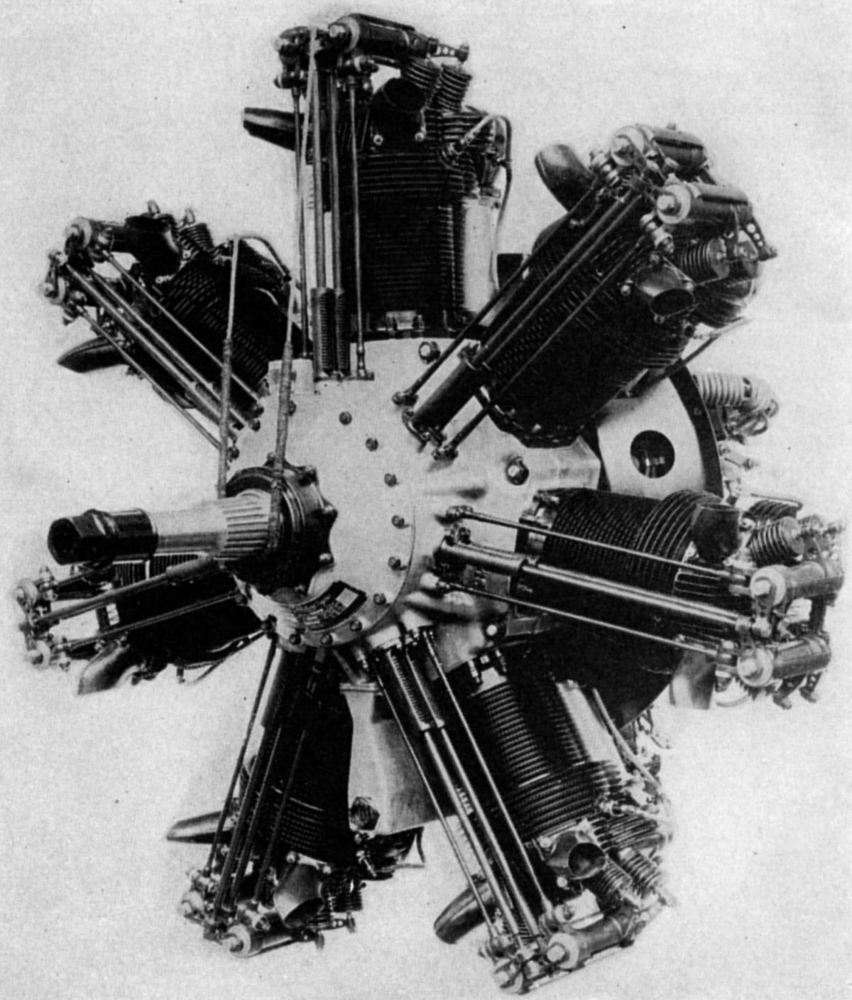
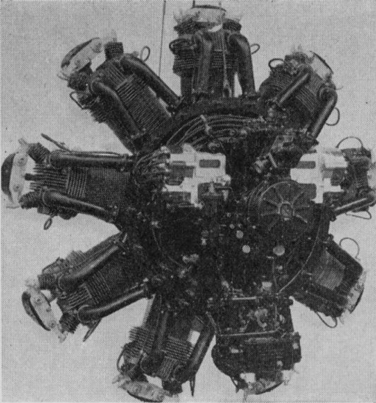
| Aft and Sectioned Views | Series IV | Series VI | Series VI.F | Series VII.F | Series VIII | Series VIII | Series VIII.F | Series VIII.F | Series X.F.BM |
The Jupiter Series III, first produced in 1922, had a 5:1 compression ratio was 5 to 1, and delivered 390 hp at 1,575 rpm and 410 hp at 1,625 rpm. Its dry weight was 729 lb, its diameter 56.5" and its length 38.15".
The Jupiter Series IV appeared in 1923, closely followed the Series III specifications, producing 400 hp at 1,575 rpm and 436 hp at 1,750 rpm. Its dry weight was 780 lb, and its outside diameter was 57.25".
The Jupiter V was an experimental engine first tested in 1923. It helped define a much improved production type, the Jupiter Series VI, which passed the Air Ministry type test in October 1925. This almost completely redesigned engine introduced many important changes — the cylinders extended further into the crankcase and the valve gear was made more compact, reducing the engine's outside diameter; the compression ratio was raised so the engine delivered more power and weighed less; the two crankcase sections were duralumin forgings instead of castings, increasing the crankcase strength and reducing its weight. resulted in the Series VIA engine and other types of which the majority of parts were interchangeable.
The Jupiter Series VIA, a further Jupiter VI development during 1927, had a 6.3:1 compression ratio, a 415 hp at 1,700 rpm normal 5,000 ft output, and a 460 hp at 1,870 rpm maximum 5,000 ft output. The Series VIAM had a 5.3:1 compression ratio, 440 hp at 1,700 rpm normal sea level output, and 480 hp at 1,870 rpm maximum sea level output. The Series VIAL had a 5:1 compression ratio, 420 hp at 1,700 rpm normal sea level output, and 460 hp at 1,870 rpm maximum sea level output. Weight was 720 lb and diameter was 53". Series VI engines of this series could be supplied with engine-driven fuel pumps, gas starter distributors, Hucks starter claw, and for Constantinesco gun gear operating cams.
The Jupiter Series VII had a gear driven supercharger instead of the earlier induction spiral of the Series VI engines. The supercharger impeller drive included a spring-gear and a automatic centrifugal clutches that prevented shock loading and insured a smooth driving torque. Fixed diffuser vanes surrounding impeller diverted the fuel-air mixture into each cylinder's induction pipe. With a 5.3:1 compression ratio and 780 lb weight, the normal output at 12,000 ft was 420 hp at 1,755 rpm and the maximum output was 460 hp at 1,950 rpm.
Jupiter Series VIII, IX, X and XI engine used Bristol-Farman type 2:1 ratio propeller reduction gears, which increased engine weight to 880 lb. These engines could be supplied with engine-driven fuel pump, Eclipse inertia starter, Hucks starter claw, hand-operated turning gear, gas starter distributor, and Constantlnesco gun synchronizing gear.
Series VIII engines with a 5.8:1compression ratio had a 440 hp at 2,000 rpm and 4,000 ft normal rating and a 480 hp at 2,200 rpm maximum rating.
Series IX engines with a 5.3:1 compression ratio had a 485 hp at 2,000 rpm sea level normal rating, and a 525 hp at 2,200 rpm maximum rating.
Series X engines with a 5.3:1 compression ratio had a 500 hp at 2,000 rpm and 1,000 ft normal rating, and a 530 hp at 2,200 rpm and 16,000 ft maximum rating.
Series XI engines with a 5:1 compression ratio had a 460 hp at 2,000 rpm normal sea level rating and a 500 hp at 2,200 rpm maximum rating.
A new Series F Jupiter passed the Air Ministry type tests in April 1929, a range of F series models was produced with various compression, propeller reduction gearing schemes and gear-driven superchargers. The Series F eliminated the closed-end steel cylinder, replacing it with an open-ended barrel that was screwed and shrunk into a forged Y alloy cylinder head. The barrel-to-head joint was scaled by a copper ring, and a steel ring was shrunk onto the outside to increase the joint's effectiveness. Two exhaust were located in front and two intake valves in the rear. Valve seats made from a special alloy were screwed and shrunk into the cylinder head. Triple concentric valve springs were fitted, and each valve stem end featured a hardened button to resist wear. Rocker arm axes were parallel with the crankshaft, and the forward rocker arm bracket ends were connected to the crankcase by tie rods to compensate for valve clearance variations due to thermal expansion. Unsupercharged engines replaced the three spiral mixture deflectors with six, which reduced the distance traversed by the mixture, permitting better distribution at small throttle openings or with lean mixtures. An exhaust heater with regulating valve was provided to insure more complete vaporization of the fuel over a range of operating conditions. The lubrication system was improved, and larger propeller shafts and hubs fitted.
Series VI.FS engines were standard service types with 6.3:1 compression ratios and weighing 775 1b. With ground throttling the engine developed 435 hp at 1,700 rpm up to 4,000 ft. The maximum output was 465 hp at 1,870 rpm
The Series VI.FH, an alternative military type with a 5.8:1 compression ratio, produced 420 hp at 1,700 rpm up to 4,000 ft and a 450 hp at 1,870 rpm maximum output.
The Series VI.FM comprised general-purpose engines with 5.3:1 compression ratio and weighing 775 lb, 465 hp at 1,700 rpm normal sea-level ratings and 500 hp at 1,870 rpm maximum ratings.
The Series VI.FL commercial engines had a 5.15:1compression ratio, weighed 775 lb, had a 445 hp at 1,700 rpm normal sea-level rating and a 485 hp at 1,870 rpm maximum rating.
Series VII.F supercharged engines were standard service types with 5.3:1 compression ratios weighing 810 lb. Their normal rating was 490 hp at 1,775 rpm and 8,000 ft. Maximum rating was 530 hp at 1,950 rpm and 8,000 ft.
Series VIII.F with 2:1 propeller reduction gearing were standard service types with a 5.8:1 compression ratio weighing 900 lb. Their normal 4,000 ft rating was 460 hp at 2,000 rpm and their maximum rating was 480 hp at 2,200 rpm.
Series IX.F engines were general purpose with a 5.3:1 compression ratio and a normal sea-level rating 515 hp at 2,000 rpm; maximum output was 550 hp at 2,200 rpm.
Series XI.F commercial engines employed a 5.15:1 compression ratio, had a 490 hp at 2,000 rpm normal sea-level rating, and a 525 hp at 2,200 rpm maximum rating.
Series X.F.BM engines had a medium ratio supercharger and 2:1 propeller reduction gears. It delivered 555 hp at 2,000 rpm and 4000 ft, and 595 hp at 2,200 rpm and 4,000ft. Dry weight was 950 lb.
Series X.F.AM engines were the same as Series X.F.BM except that the propeller reduction gear ratio was 1.524:1 and the dry weight was 920 lb.
 |
 |
| Bristol Lucifer (A39) | |
The Lucifer, originally a 1920 Cosmos design, was an air-cooled three-cylinder radial engine designed expressly for training and light commercial work. It developed 108 hp at 1,600 rpm and 118.5 hp at 1,760 rpm. With a 5.75" bore, 6.25" stroke , a 486.9 in³ displacement and 5:1 compression ratio, it weighed 325 lb. Fuel consumption was 0.55 lb/hp/hr. It was 36" long and 48" in diameter.
The Bristol-built Lucifer II passed an Air Ministry type test in 1922. It was succeeded in 1923 by the Lucifer III. Both engines followed the Jupiter cylinder design with four valves per cylinder operated in the same manner as in the earlier Jupiter designs. The single-throw crankshaft ran on roller bearings, while a bronze-backed white-metal-lined bushing was used in the master connecting rod split big end. An annular chamber cored in the aluminum barrel-type crankcase back served as a gas mixture passage from the Claudel-Hobson carburetor to the induction pipes leading to each cylinder. Two Thomson-Bennett magnetos provided dual ignition.
The Lucifer IV appeared in 1925 with several improvements that had already been incorporated in Jupiter engines. These related to connecting rod big-end construction, cylinder design, valve design, and a special atomizing chamber that formed a part of the induction system. As a result of these detailed refinements, but with no change in displacement, the rated output rose to 130 hp at 1,700 rpm and 140 hp at 1,870 rpm.
 |
 |
 |
 |
| Cherub Series I (A39) | Series III (A39) | ||
The Cherub Series I was an air-cooled two-cylinder horizontally-opposed engine first produced in 1923 with an 85 mm (3.347") bore, 96.5 mm (3.799") stroke, and 1.095 l (66.8 in³) displacement and 6:1 compression ratio that produced 25 hp at 2,500 rpm. The engine was available with either direct or 2:1 geared propeller drive. The direct-drive engine weighed 90 lb while the geared version weighed 107.5 lb. The composite cylinders used barrels with integral cooling fins turned from steel forgings, and cast-aluminum heads that were bolted to barrel flanges against copper rings serving as head gaskets. Valve seats of a special alloy were cast in place. Two interchangeable overhead valves worked in spherically-seated phosphor-bronze valve guides. A single camshaft with four cams, located directly below and parallel with the crankshaft, ran in two large phosphor-bronze bearings supported in the main crankcase walls. The camshaft was driven through spur gears from the crankshaft front end and the oil pump was driven from the camshaft rear end. The valves were operated by rock shafts that ran parallel with the cylinder axes from the crankcase to the cylinder head. These rock shafts were rockers with a central boss elongated to form of a shaft, with an inner rocker arm actuated through fingers by the cam, and the outer arm operating the valves by bearing on the hardened valve stem tips. The movement of the three was purely oscillatory, there being in no sense push rods, so the cylinder thermal expansion could not affect valve clearances. A torsion spring fitted to each rocker shaft held the inner rocker, rocker finger, and cam in close contact.
The crankcase, made up of three aluminum alloy castings, had the two main castings joined in a vertical plane on the engine centerline, supporting the crankshaft, camshaft, and auxiliary drives. The front section covered the camshaft driving gears and carried the front crankshaft bearing. The one-piece two-throw crankshaft was made from a case-hardened alloy-steel forging supported on four ball bearings, the forward one carrying the propeller thrust, and the rear one of smaller size acting as a steady bearing for the magneto gears. The connecting rods had case-hardened big ends, which were placed over the crankpins and supported on a double row of rollers. Aluminum alloy pistons were fitted with two compression rings, the lower serving also as an oil scraper. The piston-pin was full floating, and was located endwise by gun-metal buttons that were pressed into the piston pin boss ends. The wet-sump oil supply was delivered to the bearings via a reciprocating plunger pump that was always primed, and was driven through a connecting rod by an eccentric on the camshaft aft end. Oil was discharged via a sprayer directly over the big-end bearings while another passage lubricated the magneto driving gears. The amount of oil discharged was controlled by a light spring. An oil drain led the oil to the camshaft bearings, and the remainder of the engine received lubrication by splash. A flange-mounted B.T.H. magneto providing variable ignition was driven from the crankshaft end by skew gears. An integral impulse starter facilitated starting. A special Zenith carburetor, mounted at the crankcase rear, metered a fuel-air mixture that passed through cored passages to the induction pipes running parallel with and behind the cylinders.
The geared Cherub engine was, as far as possible, identical with the direct-drive version. A deeper front cover carried the front crankshaft and propeller shaft bearings. The propeller shaft axis was below the crankshaft and in line with the camshaft. Spur gears were employed on the crankshaft gear to drive a flywheel concentric with and driven front the crankshaft. This flywheel incorporated a spring drive to dampen torque pulses. The propeller shaft rear bearing replaced the camshaft front bearing, the front end of which was carried in the propeller shaft end, from which it was driven.
The Bristol Cherub Series III passed the Air Ministry type tests in December 1925. Following the abandonment of Royal Aero Club cylinder capacity ratings for lightplane engines, this engine was enlarged to meet the power requirements of a two-seater class. The cylinder bore was increased to 90 mm (3.543") and the stroke remained at 96.5 (3.799"), resulting in a new 1.228 l (75.0 in³) displacement and 5.5:1 compression ratio. The Series III developed 33 hp at 2,900 rpm and 32 hp at 3,200 rpm, weighed 100 lb, was 18.936" long, 25.474" wide and 17.998" high. The aluminum cylinder head was redesigned and fitted with new valves and triple springs. Alloy-steel valve seats were screwed into the cylinder head. The cylinders were attached to the crankcase by a spigoted and flanged joint, a synthetic rubber ring being used to keep the joint oil tight. A compression ring was added so that each a aluminum piston was fitted with two compression rings and one oil-scraper ring in the new model. The crankcase was made smaller, eliminating the oil supply well. The lubricating system became a dry-sump full-pressure type, a duplex gear pump providing a pressure and scavenging unit. The connecting rod big ends were fitted with hardened steel liners pressed into place. These were large enough to be fitted over the crankpin, where, in position, split bronze floating bushings were inserted and the two halves and secured together by screws that were locked by split pins. The engine aft end was modified to provide an improved engine mount. A detachable rear crankcase cover carried a white-metal-lined plain bearing for the crankshaft aft end into which pressurized oil supplied the connecting rod big-end bearings. The double-pole double-slip-ring magneto fired two plugs in each cylinder. The ignition control was automatic and interconnected with the throttle. A special Cherub type Zenith carburetor was bolted to a T-shaped induction casting attached to the magneto and pump housing underside. From this induction T-piece, pipes led directly to each cylinder inlet port
The Bristol Titan Series II was a commercial air-cooled five-cylinder radial engine introduced in 1927, which closely followed the Jupiter in design and construction. With a 5.75" bore, 6.50" stroke, 843.9 in³ displacement and 5:1 compression ratio, it was rated 200 hp at 1,700 rpm and 220 hp at 1,870 rpm.
 |
 |
 |
| Titan (A39) | Neptune (A39) | |
The Titan Series III engine had a 5.3:1 compression ratio and was rated 220 hp at 1,700 rpm and 240 hp at 1,870 rpm. Dry weight was 500 lb. The pistons and cylinders were interchangeable with the Jupiter series, forged cylinder heads being introduced in later Titan engines. The master connecting rod had a solid big end fitted with a one-piece floating bustling. The single-throw built-up crankshaft followed Jupiter engine practice. The crankcase construction was similar to the Jupiter in being split in the cylinder plane, but instead of the spiral induction system in the rear casing, a centrifugal fan was driven from the crankshaft rear. A Bristol Duplex carburetor supplied mixture and a conical steel stamping attached to the crankcase mounted the engine to the airframe.
The Neptune was an air-cooled seven-cylinder radial engine that followed Jupiter design and construction, but used an impeller instead of the previous spiral induction path. With a 5.75" bore, 6.50" stroke, and 1,181.5 in³ displacement, the Neptune was rated 290 hp at 1,700 rpm and delivered 315 hp at 1,870 rpm. Weight was 630 lb.
 |
 |
 |
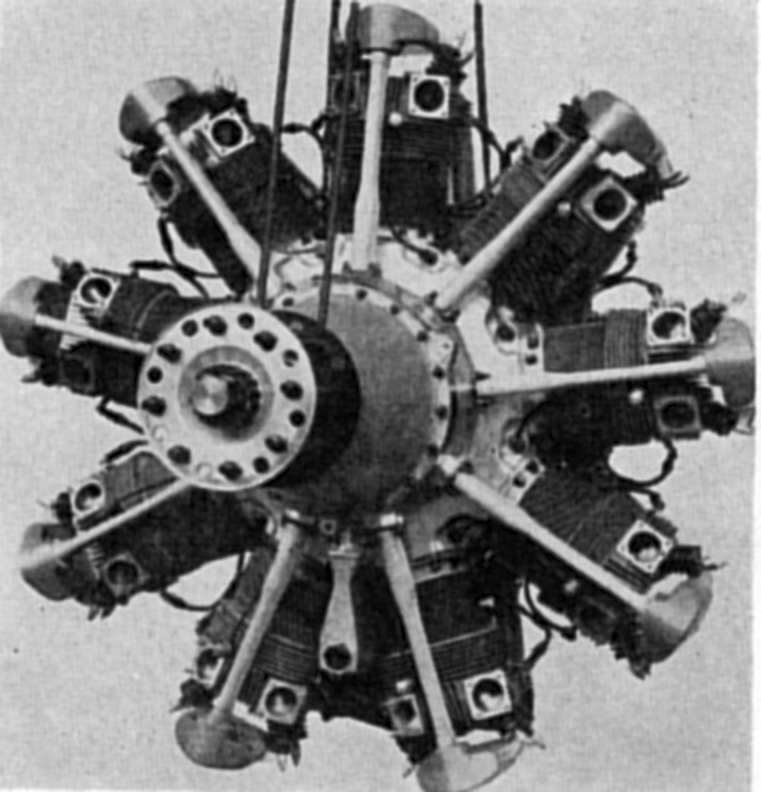
| Bristol Mercury (A39) | ||
Bristol the Mercury in 1926 for use in the 1927 Schneider Trophy race. It was an air-cooled nine-cylinder radial engine of exceptionally high power/weight. The Mercury generally followed Jupiter design principles, but its diameter was reduced by a shorter stroke, cylinder head and valve gear changes. It also introduced a gear-driven supercharger.
The Mercury I racing engine, with a 5.75" bore, 6.50" stroke and 1,519.1 in³ displacement, developed over 8oo hp at 2,500 rpm from a 680 lb dry weight. It was developed into a military series.
The standard Mercury IVS.2 of 1932 had a normal crankshaft speed of 2,250 rpm which, with a 1.5267:1 reduction gear ratio, gave the propeller a normal speed of 1,475 rpm .The maximum engine speed was 2,600 rpm, which produced a 1,700 rpm propeller speed. At 13,500 ft and normal rpm, the engine produced 510 hp. Its peak output at maximum rpm and 16,500 ft was 560 hp, while maximum takeoff power was 530 hp. Weight was 940 lb.
Mercury cylinders were composite with open ended steel barrels screwed into initially cast, later forged, aluminum heads. The cooling fin arrangement was improved over the Jupiter design, and the overhead rocker mechanism was completely enclosed and could be lubricated from a single grease fitting. Valve clearance adjustment required removing the valve cover. The temperature compensating feature, which maintained constant valve clearance, was retained. This new valve gear not had less form drag, but oval push rod tubes further reduced drag. The solid master rod big end was increased in diameter and employed a floating steel bushing, coated inside and outside with white metal, for the master rod bearing. The link rods were longer and had a new and stronger shank section that eliminated the deep cylinder skirt scallops. Link rod knuckle pin bearing size was also increased. The full skirt pistons, machined all over from duralumin forgings, used two compression rings and two oil-scraper rings. The crankshaft was stiffened by increasing the main bearing journal and of the crankpin diameters. The engines were mounted on a flanged conical steel plate that was sandwiched between the crankcase and the supercharger. This afforded a large-diameter mounting bolt circle and a degree of vibration damping. Flexible rubber vibration absorbers could also be fitted. The magnetos were mounted transversely and were more compactly housed. An inertia starter, which might be energized electrically or by hand, was mounted centrally on the rear cover.
The rear cover design permitted building the supercharger as a separate unit, thereby providing a simple means to obtain different blower characteristics. The supercharger impeller was driven from the crankshaft rear through a gear train. A spring drive dampened cyclic shocks, and automatic centrifugal clutches in the planetary pinions eliminated shock load from excessive acceleration due to rapid throttle opening. As in the supercharged Jupiter engines, an automatic boost control reduced pilot workload. This device maintained the maximum permissible boost pressure up to the rated altitude, but allowed the pilot to manually throttle the engine. An overriding device could be fitted to permit an over boost when additional power was necessary as in a take-off. At the same time, the mixture was automatically richened. The ignition advance was also controlled automatically. Bristol-Farman bevel reduction gearing was retained for driving the propeller. The assembly was redesigned and, as a result, it was more compact and about 12 lb lighter than the Jupiter assembly. The reduction gear housing was forged rather than cast aluminum.
The later Mercury VI was developed to take advantage of 87 octane fuel. Among the design improvements was a 6:1 compression ratio, nitrided cylinder barrels and nitrided crankshaft journals. The takeoff rating was 620 hp at 2,400 rpm, and 605 hp was developed up to 12,500 feet. Dry weight was 975 lb, outside diameter 51.5", overall length 53.8", and the mounting ring diameter was 28.75". Two B.T.H. SC. 9-4B magnetos furnished ignition, and the mixture was formed by an AVT.80B Claudel-Hobson duplex carburetor. Inlet valves opened 29° early and closed 47° late; exhaust valves opened 76° early and closed 40° late.
Bristol continued to build the Mercury engine line after 1930, replaced the Jupiter with the Pegasus, embarked on a series of very successful sleeve-valve engines, and ultimately became a major gas turbine producer. Bristol merged with Armstrong Siddeley in 1959 to form Bristol Siddeley, which Rolls-Royce bought in 1966.
 |
 |
 |
| Bristol Pegasus(A39) | ||
References
Angle, Glenn D, ed. Aerosphere 1939 (New York, New York: Aircraft Publications, 1940).
Image Sources: A39 = Aerosphere 1939; AEE = Airplane Engine Encyclopedia; NARA = U.S. National Archives and Records Administration; UKNA = United Kingdom National Archives.
Send mail to
![]() with questions or comments about this web site.
with questions or comments about this web site.
![]()