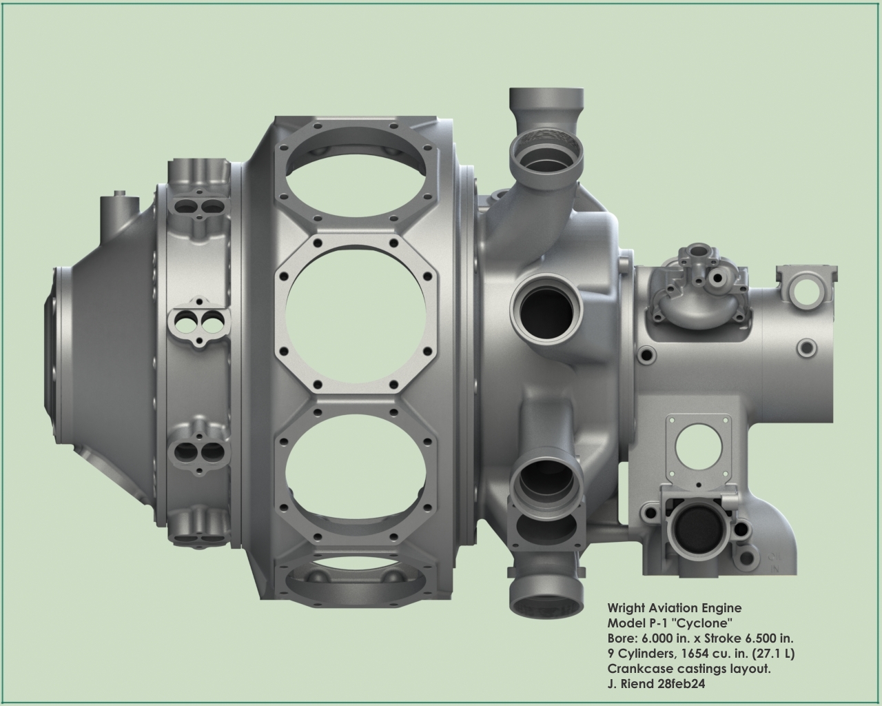
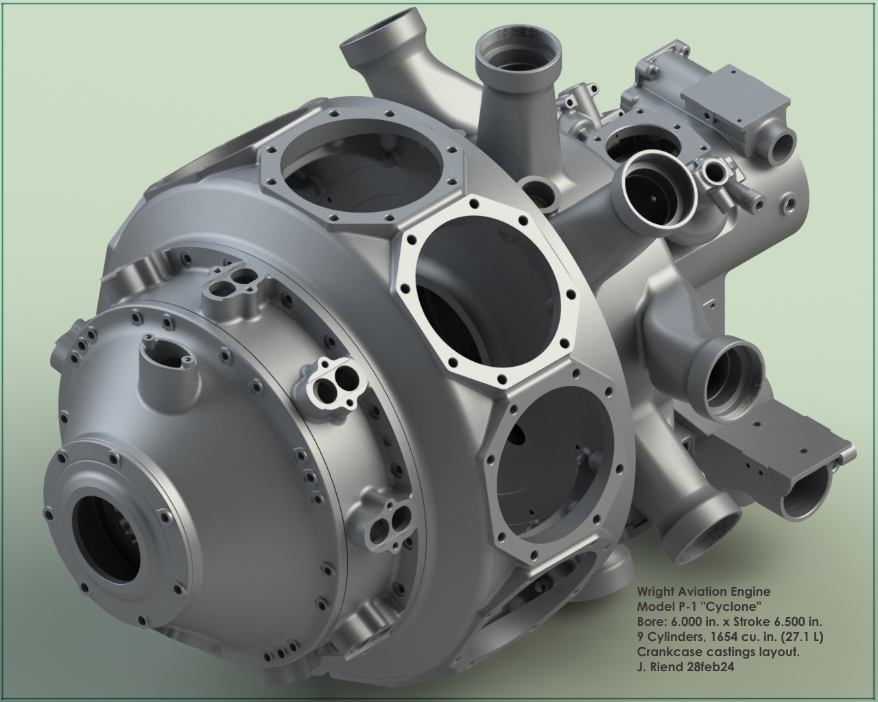
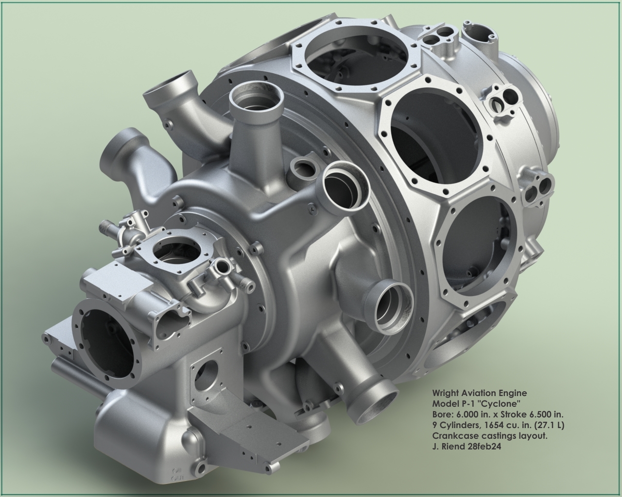
Wright Aviation Engine, Model P-1 "Cyclone"
by J. Riend
Published 1 Mar 2024; Revised 1 Oct 2024
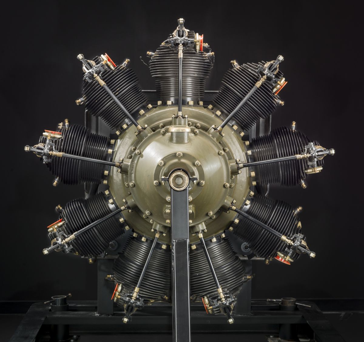
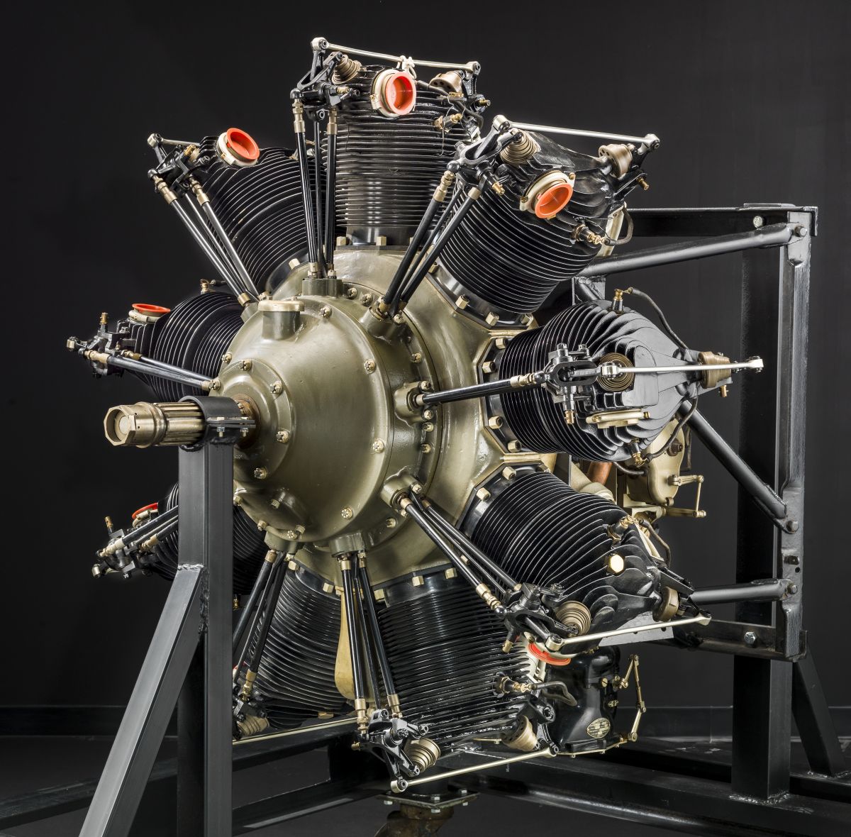
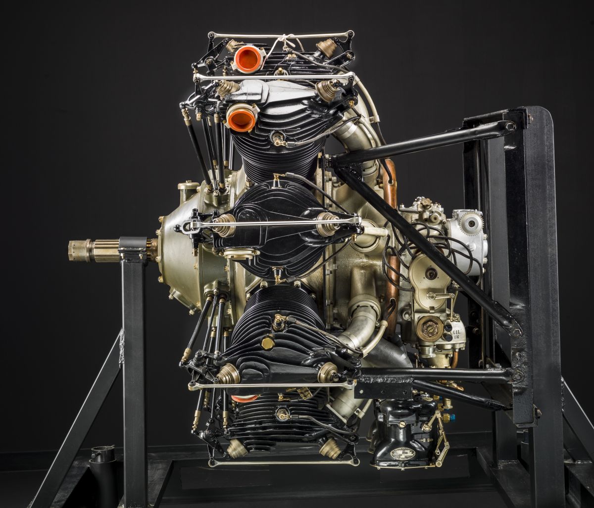
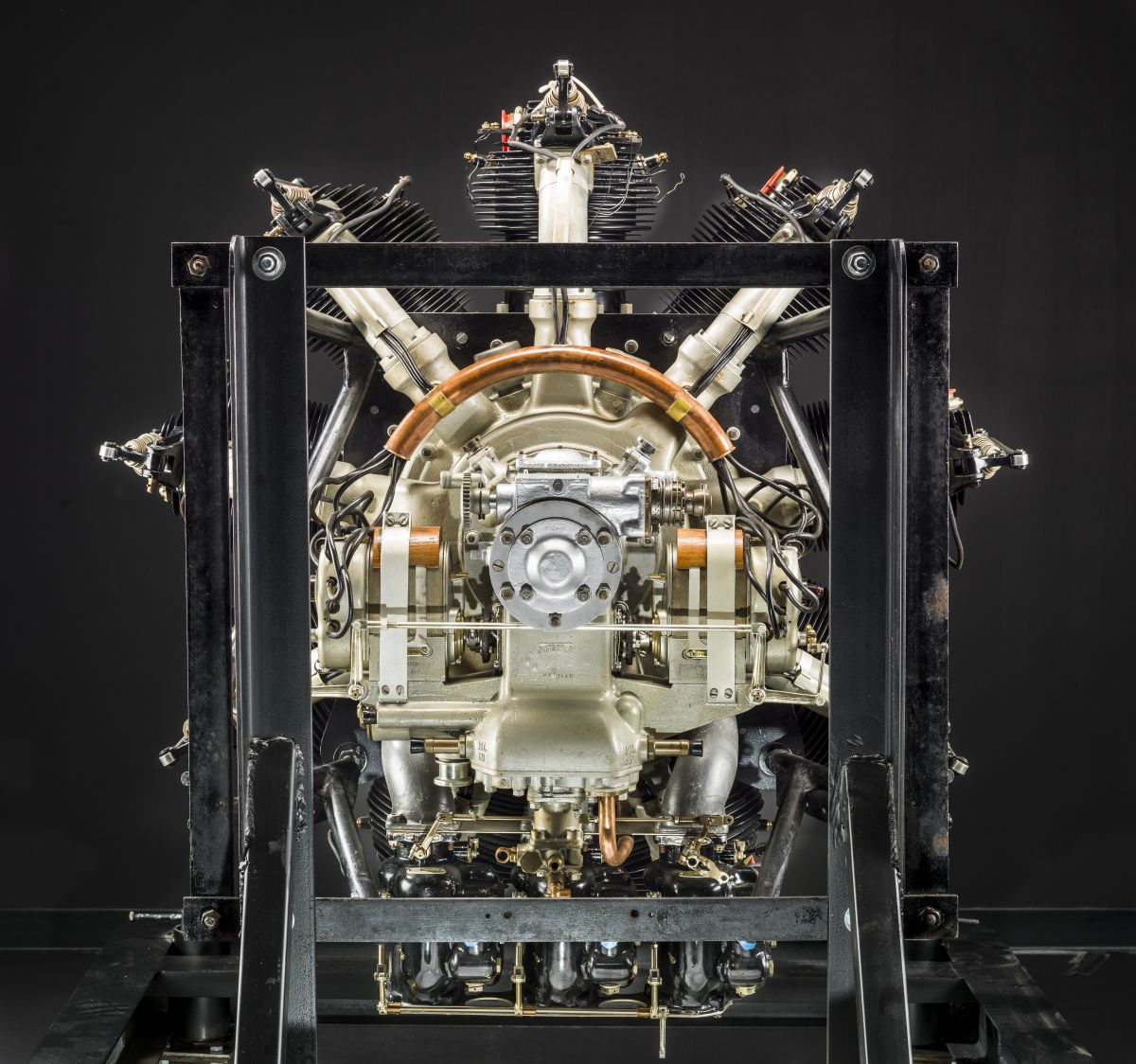
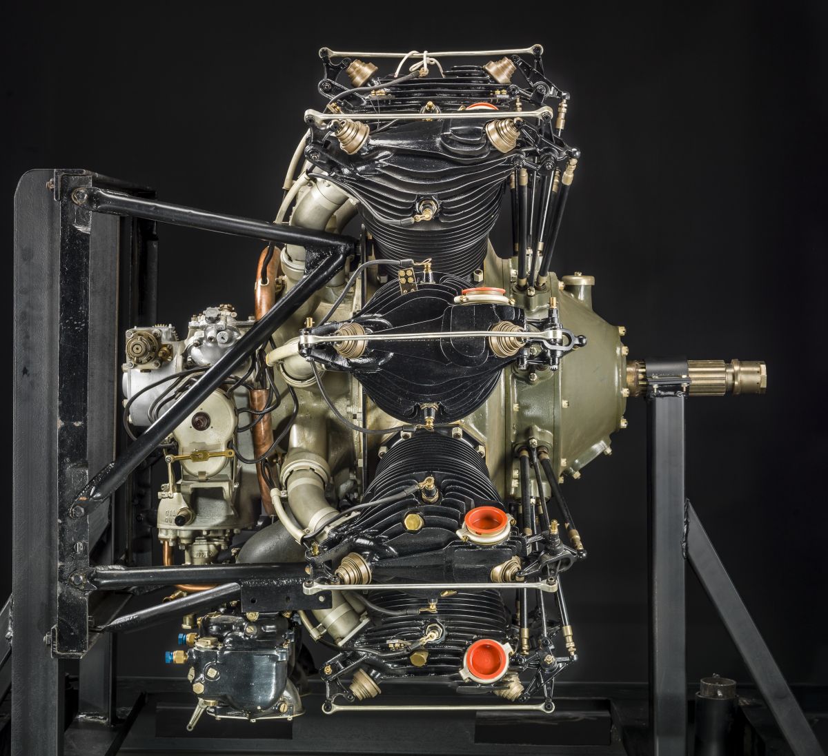
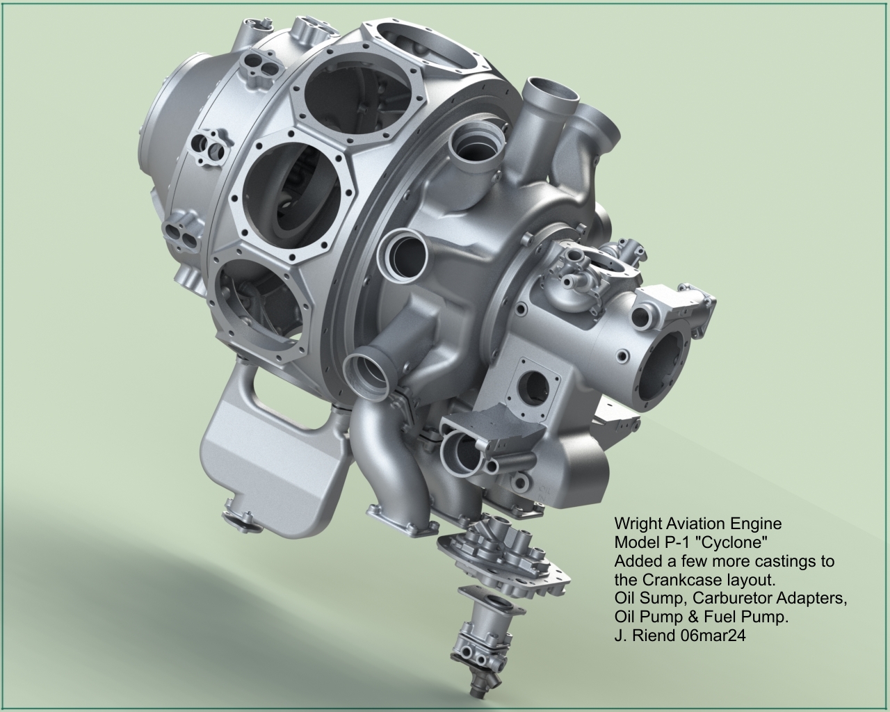
| Early in 1925, the Wright Aeronautical Corporation was busy working on the first large 400-horsepower class radial engine that was to become the Model P-1 Cyclone, the forerunner of a very successful aircraft engine line. |
Wright P-1 Drawing Quick Reference
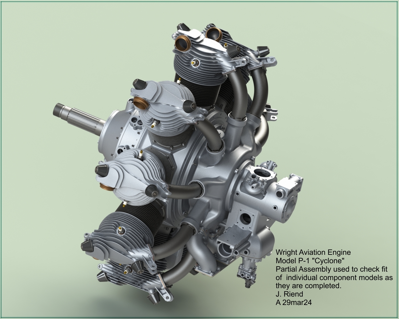
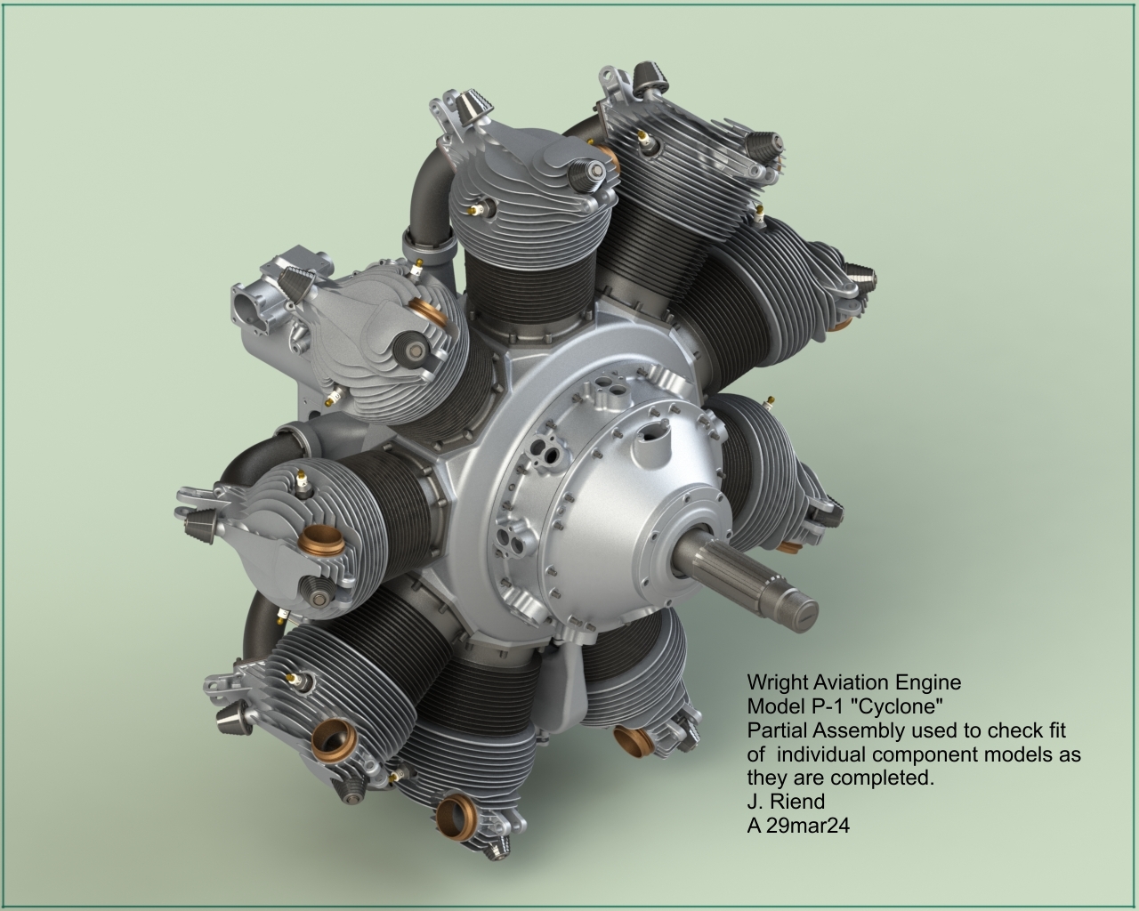
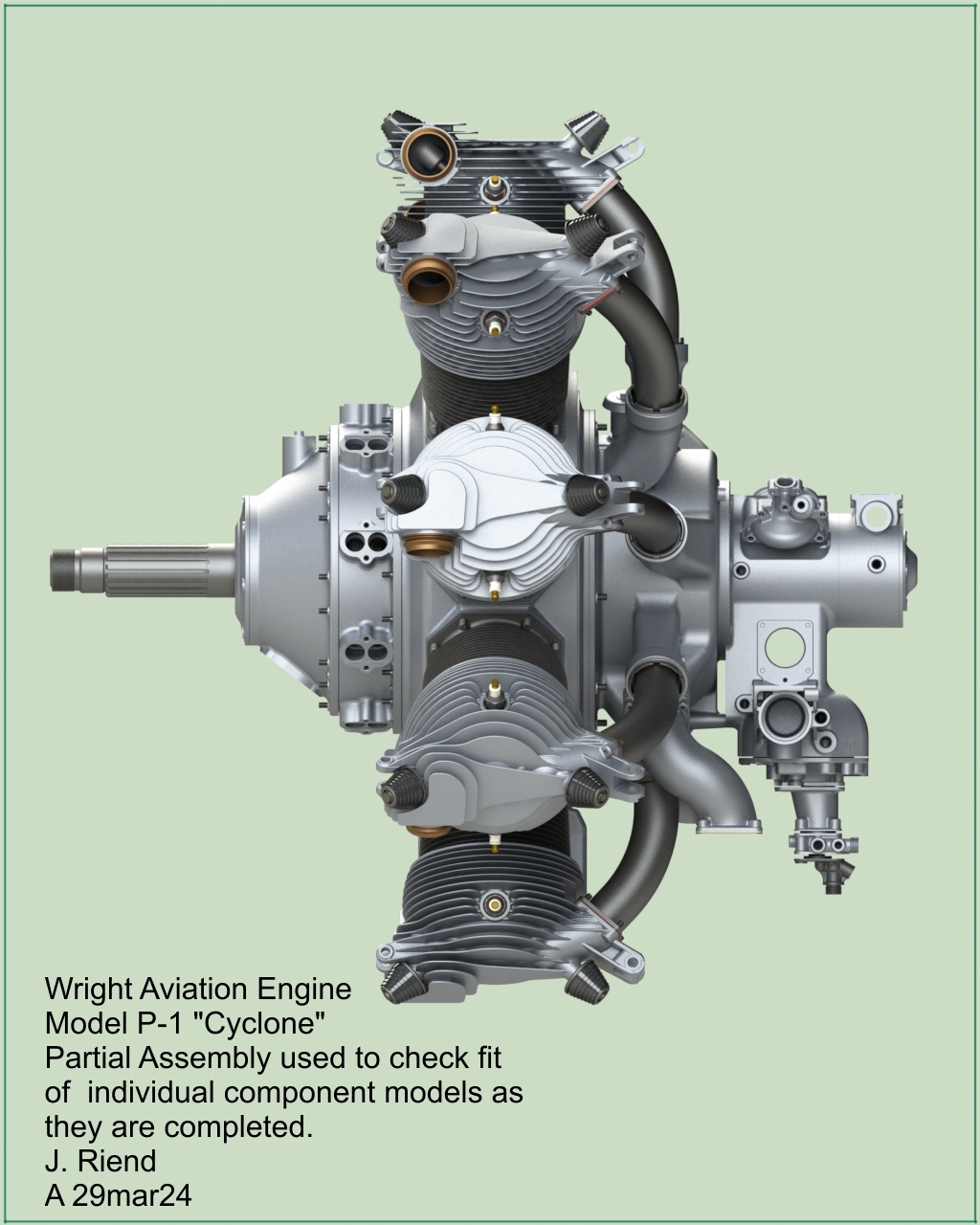
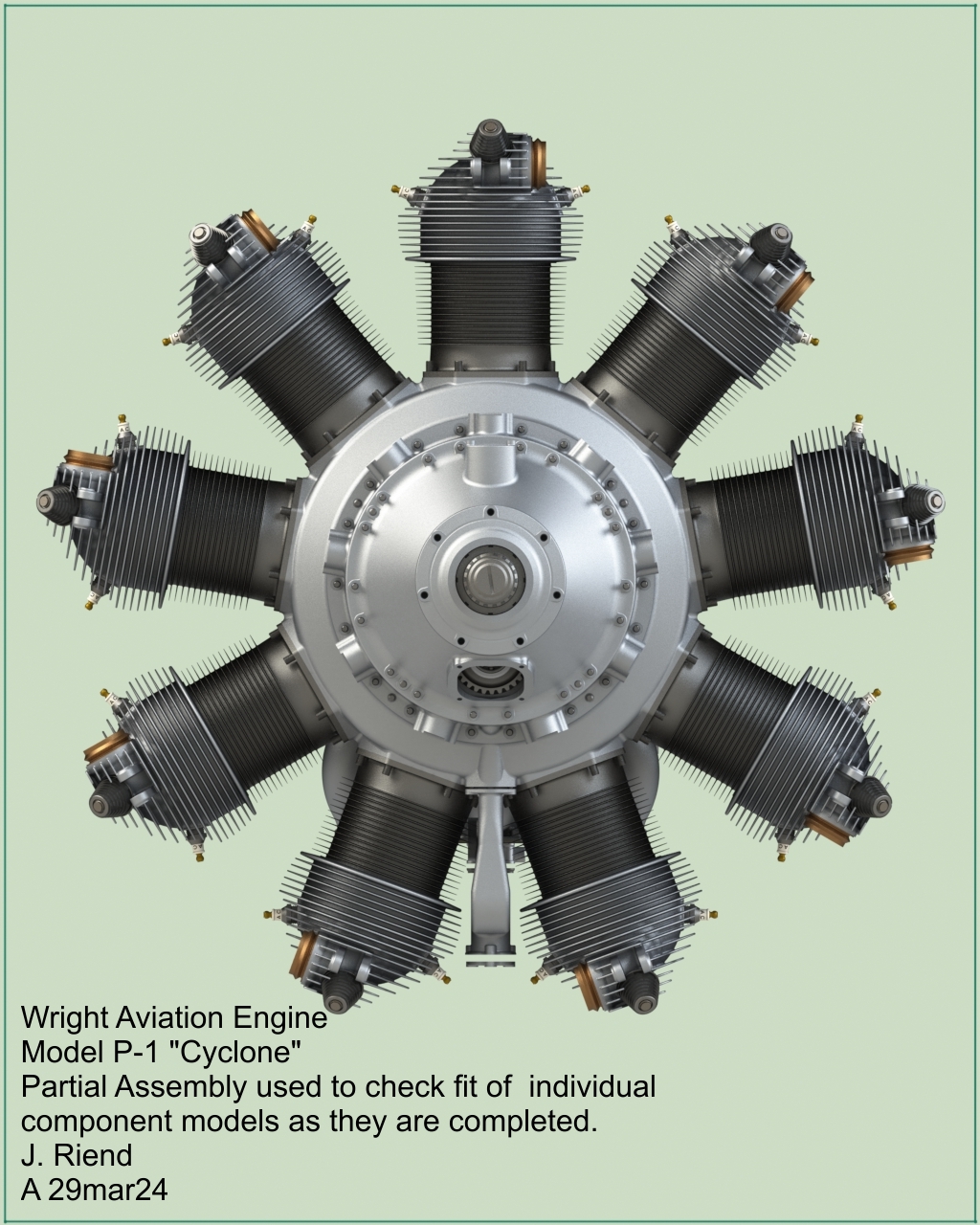
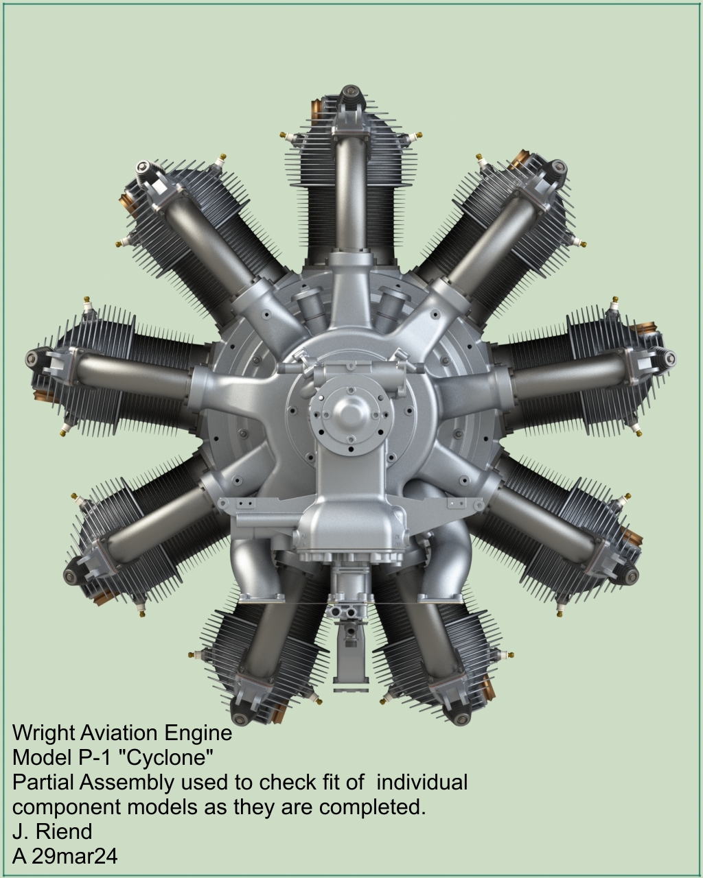
| Crankcase Layout | Cylinder | Valve Train | Partial Assembly |
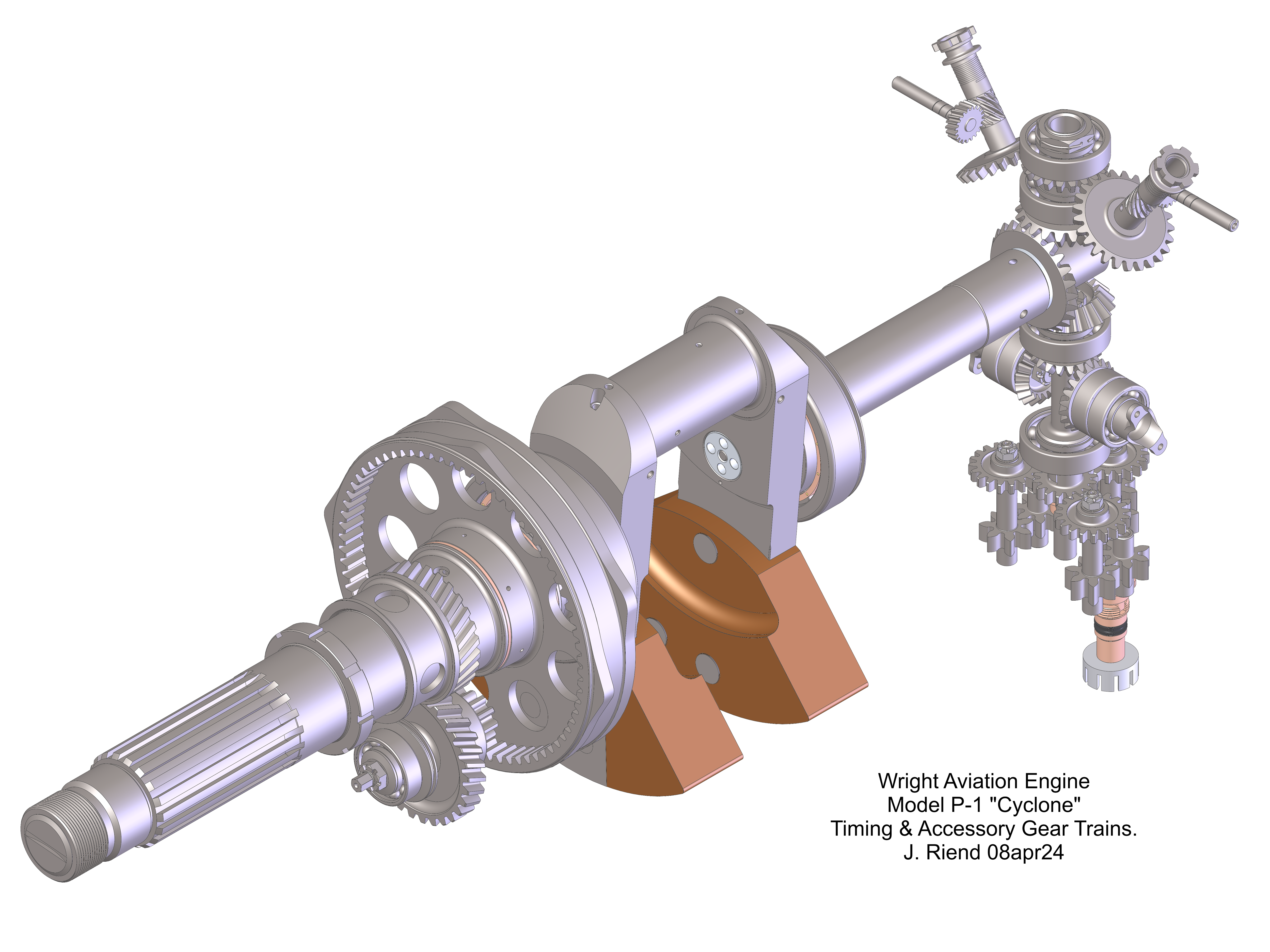
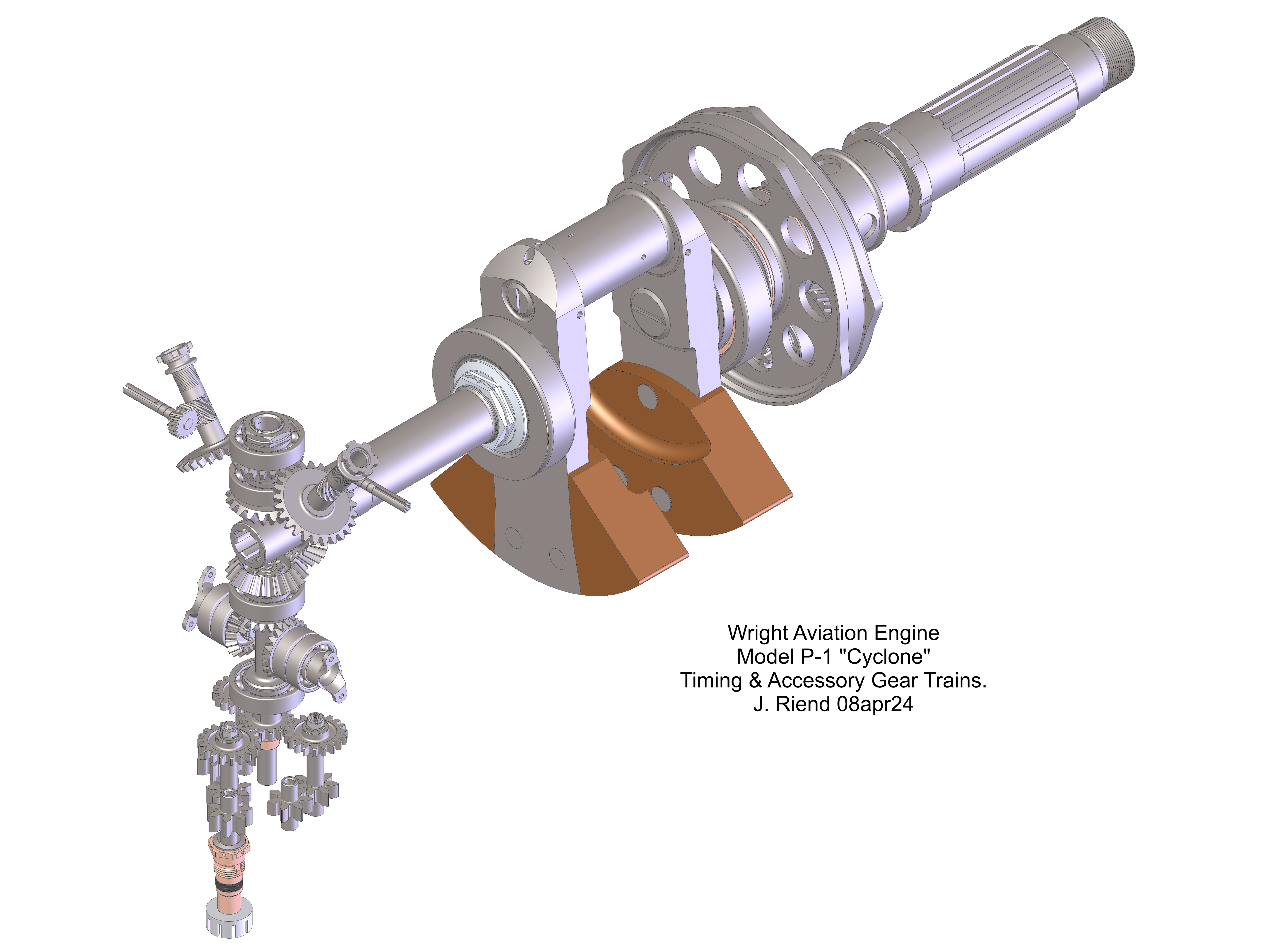
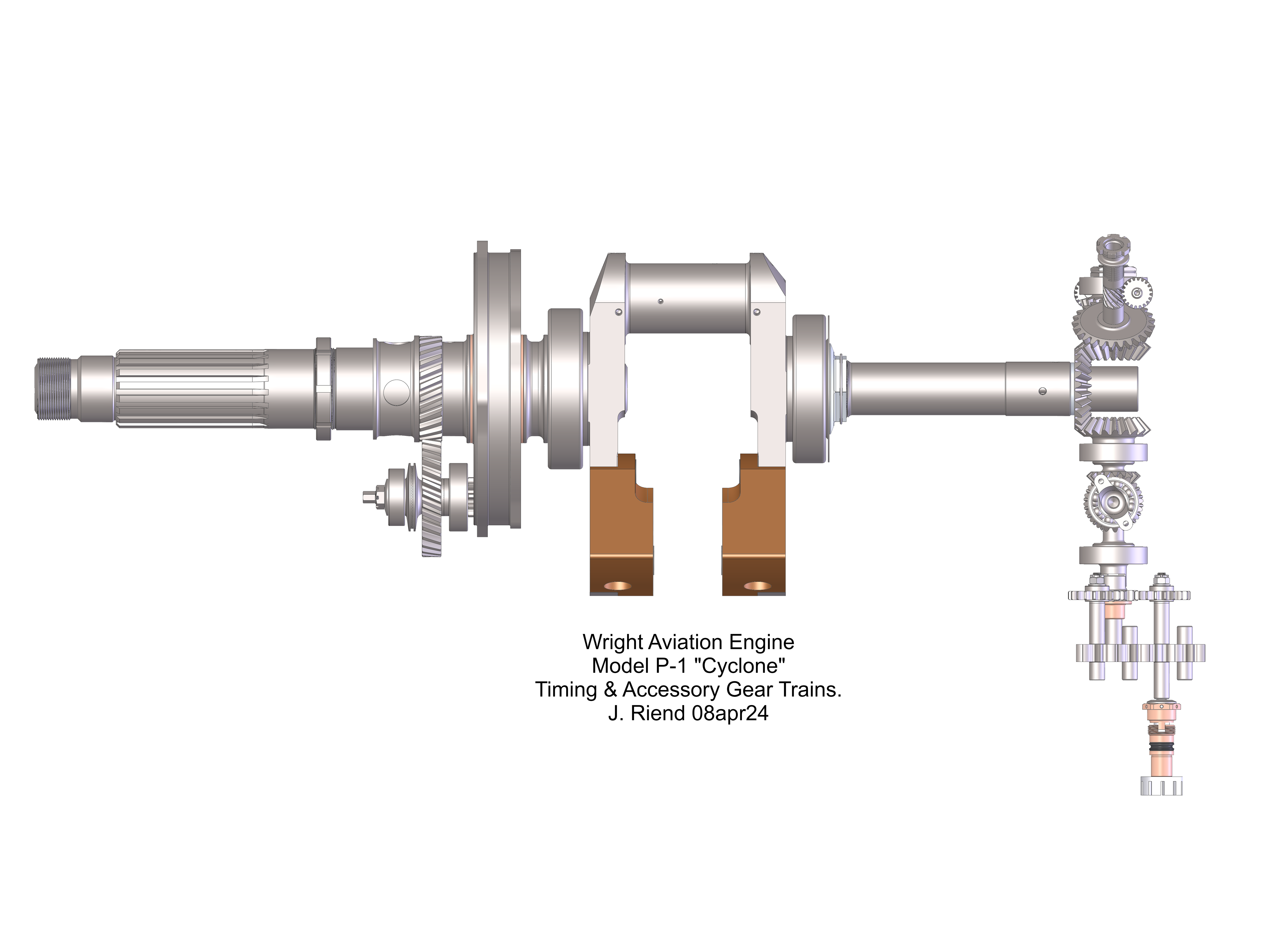
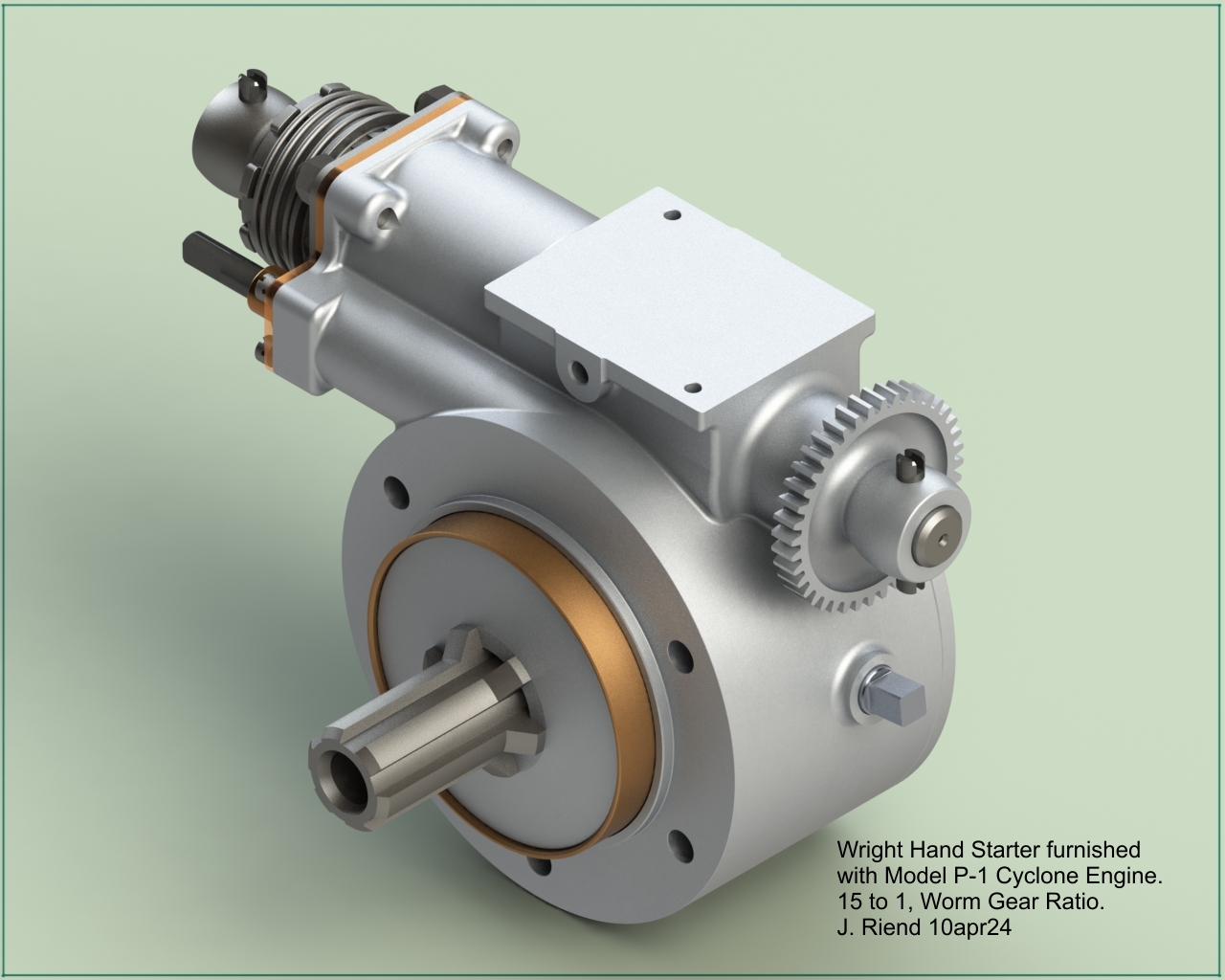
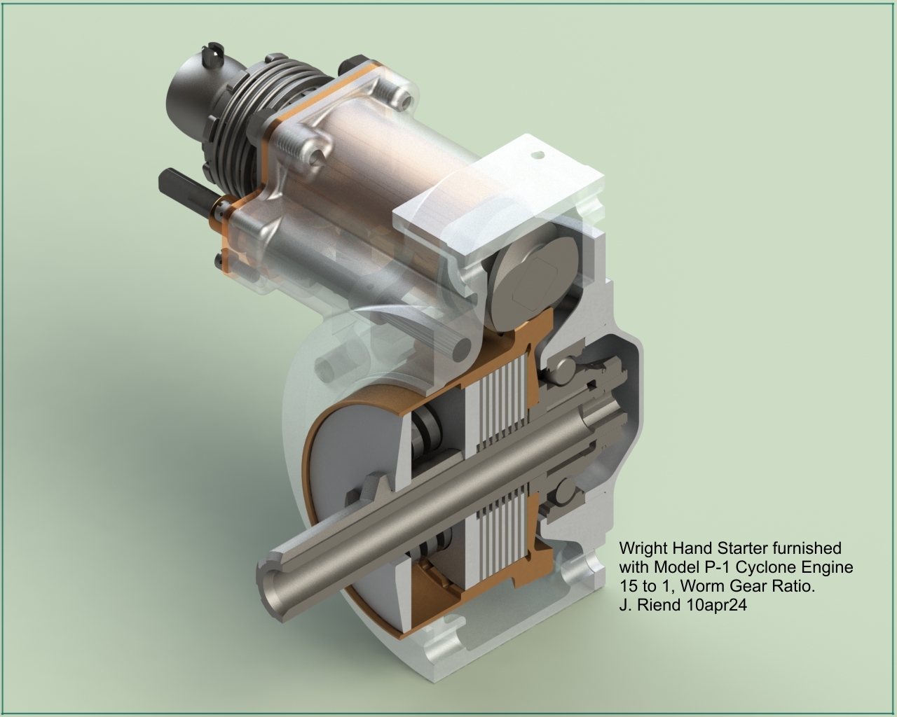
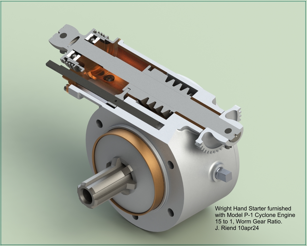
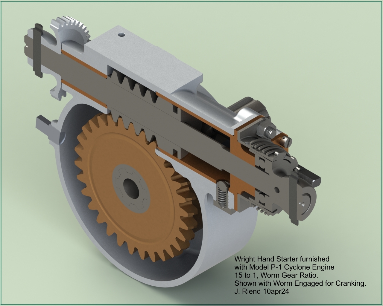
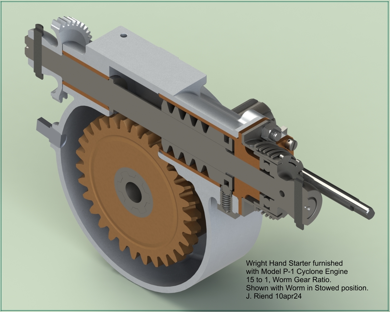
| Complete Assembly | Front Section, Prop Hub | Gear Trains | Starter Assembly |
Project Description
1 March 2024
To date there has been very little technical information available about these ground breaking engines. There are a few photographs available online at AEHS and the National Air and Space Museum (NASM), and some endurance test run documents at NASM; that’s about it. There are however the original Wright drawings of these engines stashed away in the WAD engine drawing microfilm archive at Wright State University.
I originally started 3D modeling the Wright P-2 engine because it appeared to have the least number of missing drawings (yes, some drawings are missing, not filmed or unreadable). I had hoped to be able to complete the entire engine. While working on the P-2 supercharger section, I continued searching the archive for additional drawings of these (P-1, P-2 and R-1200) engines and got very lucky, hitting on a version of the P-1 cylinder head drawing. It was actually the P-1, and its unique and elaborate valve train mechanism, that piqued my interest in researching the large Wright radials. Having found that cylinder head drawing, I now have a complete P-1 drawing set and will be able to complete that project. I decided to postpone modeling the P-2 and move forward on the P-1 project.
|
|
|
|
|
| Wright Aviation Engine, Model P-1 (Photos from NASM (CCO)) | ||||
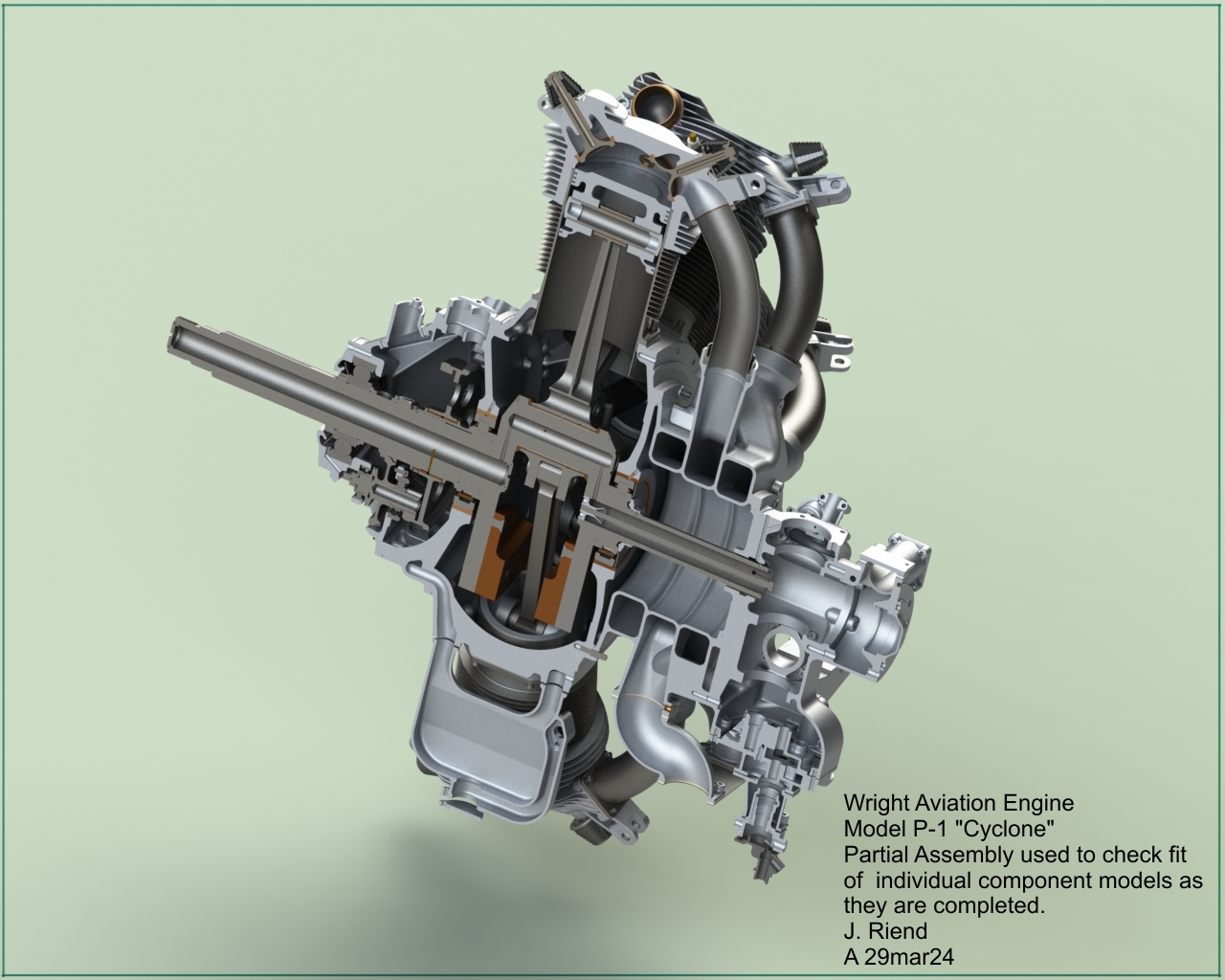
The P-1 renders and drawings that follow are my interpretation and faithful representation of the Wright drawings. The scans of the original drawings are not always fully legible, show every detail and may have questionable dimensions. These discrepancies can usually be overcome by comparing dimensions and features on associated components. However, in some cases (very rarely) there is not enough information or modeling skill set to fully render some features details. Now, for your enjoyment, the historical P-1 Cyclone.
17 March 2024
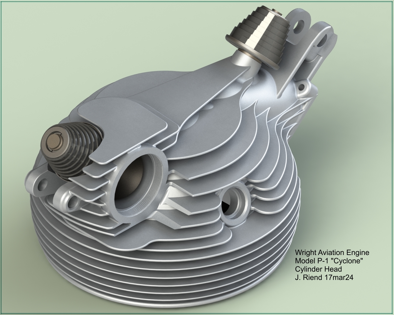
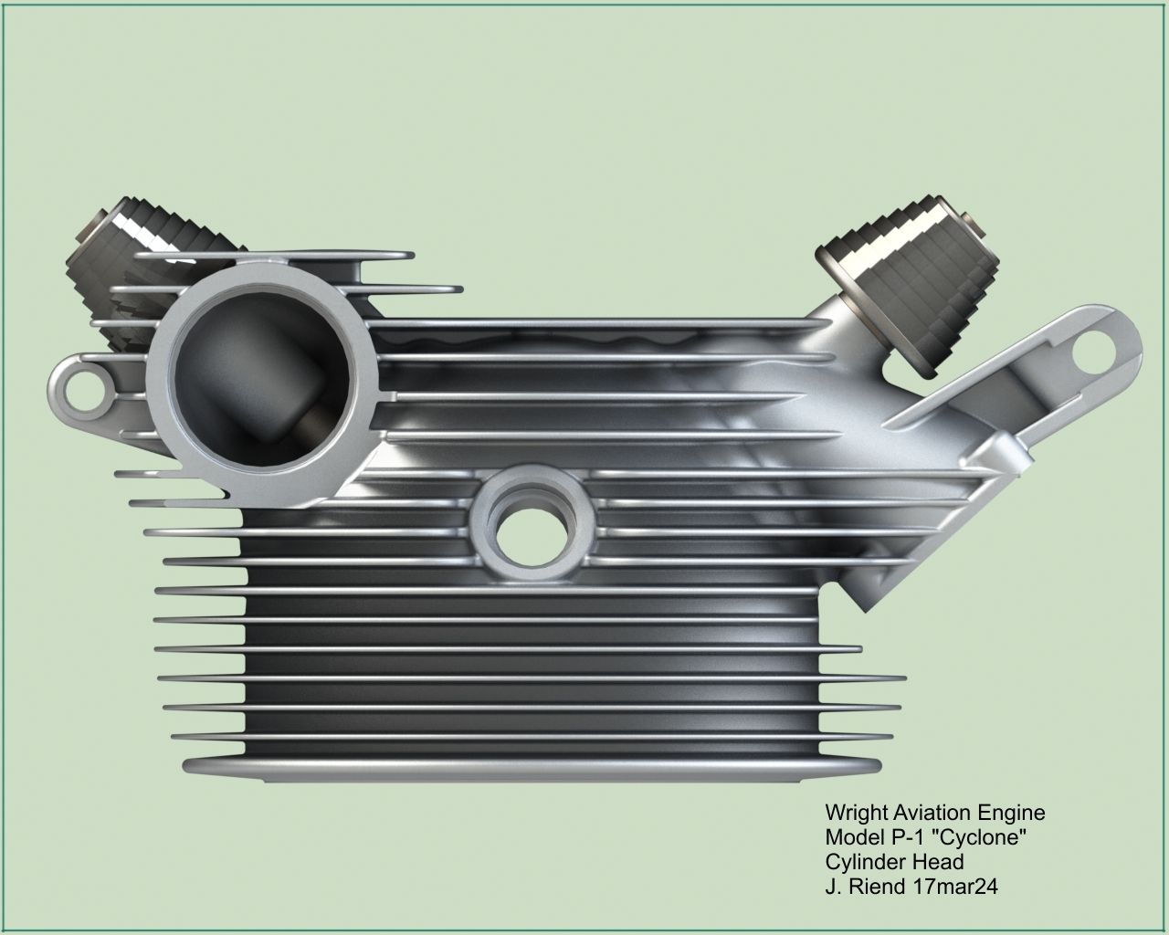
In the interest of full disclosure, the P-1 cylinder head intake and exhaust runners were designed with equal (more or less) flow area along their length. Unfortunately, these runner features exceed my current level of 3D modeling expertise. As a result, I opted to model the runners with uniform width, leaving out those features, which means that the normal bulges in the runners around the valves are not present in this model.
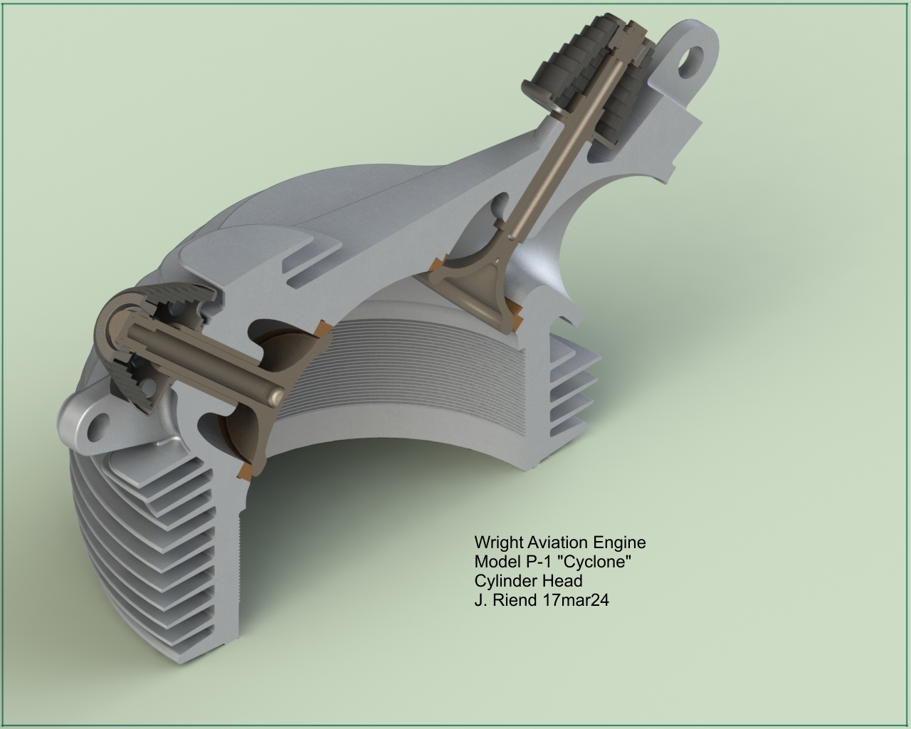
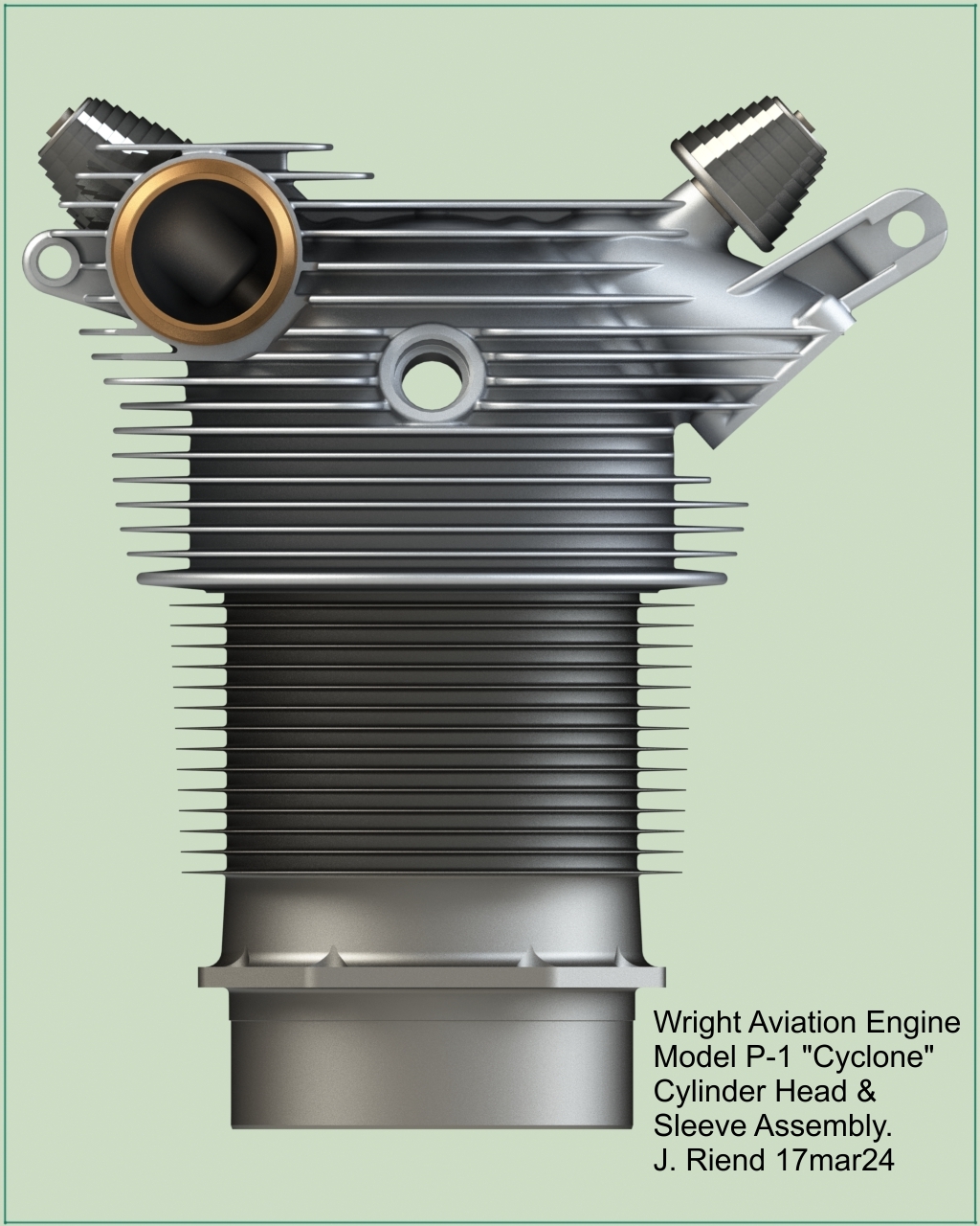
An interesting feature of the cylinder head and sleeve assembly is the very long (26 turns) 6-5/16"-16 thread. The sleeve is assembled with an 0.0185" interference fit. The components must have been assembled at room temperature, because the change in pitch over the engagement length would have made it impossible to screw the sleeve in if the head were heated for a shrink fit. Wright obviously had years of experience with these fine-threaded sleeves in its Hispano-Suiza engines. Anyone have any documentation on how they actually performed this assembly operation?
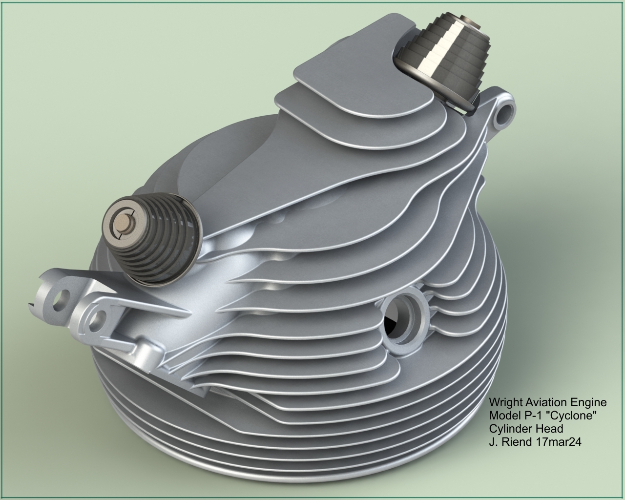
Another interesting feature of the P-1 is the tungsten steel alloy (10040-W60A US Air Corps) used for both the valves and valve guides. They must have squirted grease under the spiral springs thru holes in the lower spring washer. These engines had to be a real mess to fly behind.
29 April 2024:
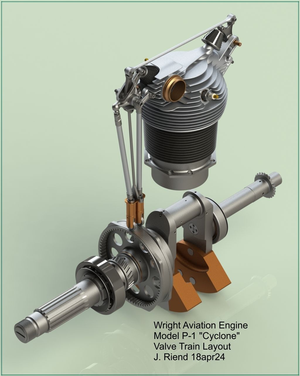
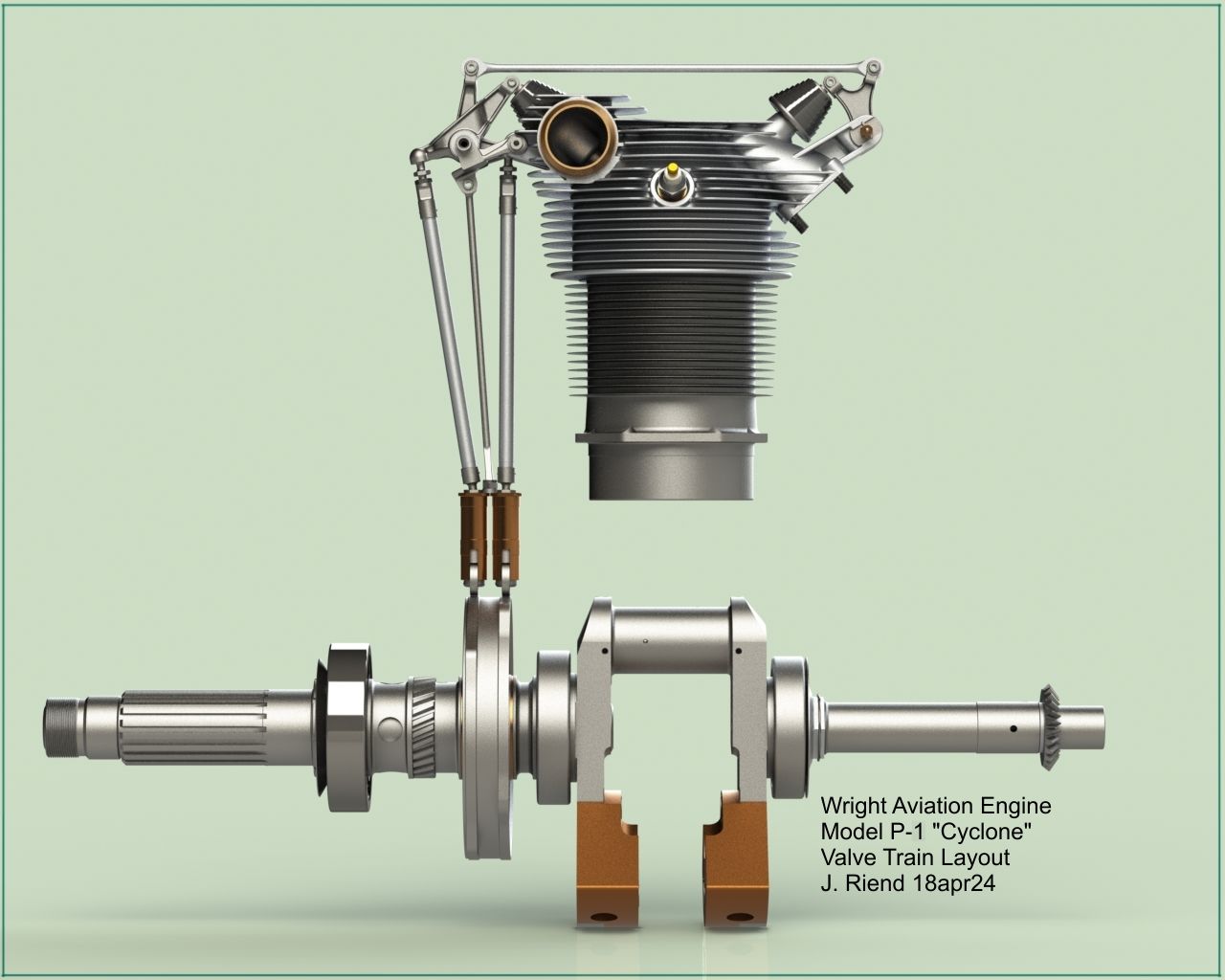
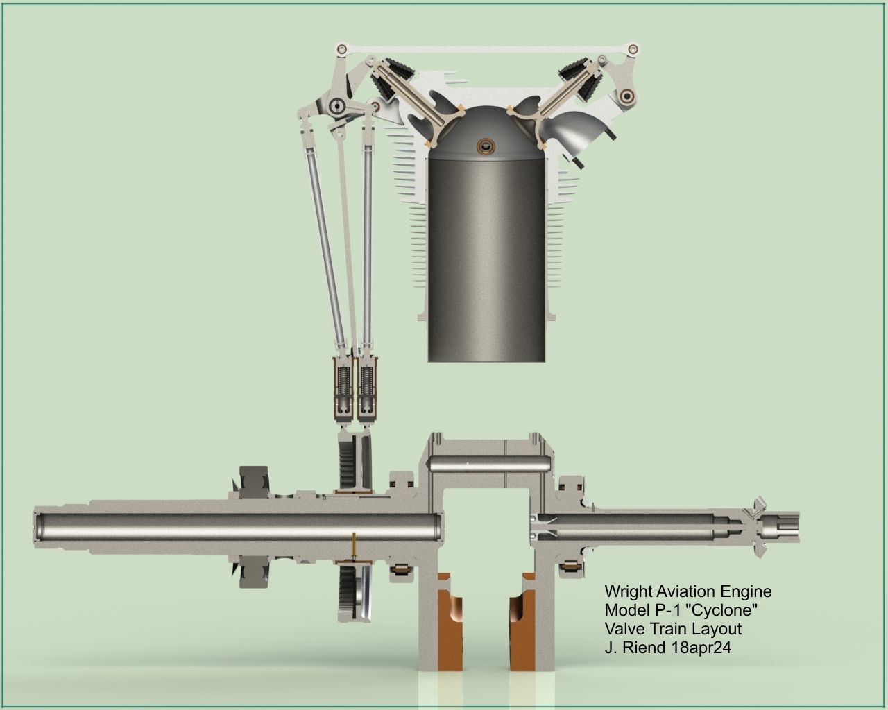
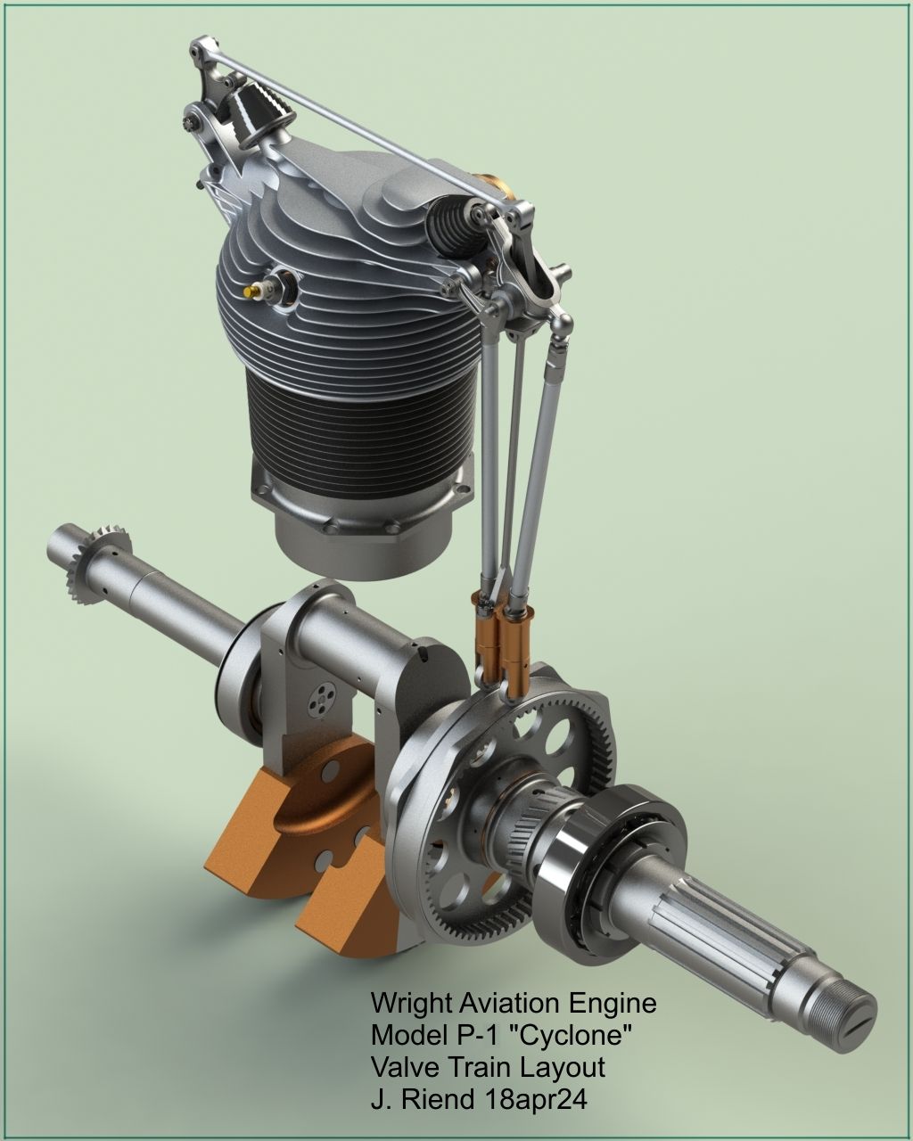
CAD modeling the Wright P-1 has been an interesting experience, exploring the details of Cyclone engine evolution. Having previously modeled the Wright J-5C Whirlwind and the Wright P-2 supercharger section, it became apparent that many of the components were shared and had evolved from the Lawrance J-1 and Wright R-1 engines. The P-1’s intermediate and main crankcases, intake case, crankshaft and master rod were essentially enlarged similarly designed versions of those in the J-5 engine. The P-1 differs from the J-series engines in its cylinder head valve placement and the valve operating mechanism. The originator of this unique valve arrangement is revealed in a 1927 (filed in 1924) patent issued to Charles L. Lawance that illustrates the cylinder head, valve placement and operating mechanism details (2). One can assume that Lawrance collaborated with S. D. Heron, who, consulting for the Air Corps, designed the cooling fins and salt cooled valves for the J-5, P-1, P-2, R-1454 and many other 1920s-era cylinder heads. Notes 3 and 4 below cover some of many good historical notes outlining early Cyclone engine development and the only P-1 test document I have found.
 |
 |
 |
| P-1 Valve Gear Patent | P-1 Undergoing Test | Wright P-1 in Douglas DT-6 |
1 May 2024
I included the BuAer Report front section that gives an excellent outline of the P-1’s development. The full report with test data, diagrams, charts may be obtained from the NASM (4).
References
(1). Wright Cyclone P-1, Radial 9 Engine | National Air and Space Museum Images
NASM-A19710881000-NASM2014-04108.jpg
NASM-A19710881000-NASM2014-04109-000001.jpg
NASM-A19710881000-NASM2014-04115.jpg
NASM-A19710881000-NASM2014-04116.jpg
NASM-A19710881000-NASM2014-04121.jpg
(2). U.S. Patent 1,621,326
(3). Excellent historical accounts of Air-Cooled engine development written by some of the original participants.
Dinger, H.C., Capt, USN. "The Development of the Wright Air-Cooled Engine. Journal of the American Society of Naval Engineers, vol 38 no 4 (Nov 1926): 856–878.
Heron, S.D. Air Cooled Cylinder Design. SAE Transactions vol 17 pt 1 (1922): 347–430.
Lawrance, C.L. Air Cooled Engine Development. SAE Transactions vol 17 pt 1 (1922):431–437.
Mead, George. J. Some Aspects of Aircraft Engine Development. SAE Journal, vol 17 no 5 (1925):809–851.
Misenko, Albert. The McCook Field Years 1917-1927, AFRL-PR-WP-TR-1998-2080. Propulsion Directorate, Air Force Research laboratory, Wright-Patterson Air Force Base, Ohio (Feb 1995):105.
The Trend in Aircraft Engine Development. Journal of the American Society of Naval Engineers, vol 38 no 1 (1926) 695–717.
Wilson, E.E. American Air-Cooled Aircraft Engines. Journal of the American Society of Naval Engineers. vol 39 (1927):695–717.
Schlaifer, Robert and S. D. Heron. Development of Aircraft Engines and Fuels, Boston, Harvard (1950):182–186.
(4). 50 Hour Endurance Test and Sea Level Performance Characteristics of the Wright Model P-1 Engine #10062 Mfg. # 6477, WAC-15. Wright Aeronautical Corporation, Paterson, New Jersey (1 Apr 1925), NASM Propulsion Tech Files, BW-719000-01.
Wright P-1 Renders
 |
 |
 |
 |
 |
 |
| Crankcase Castings | Rear Section Assembly | ||||
 |
 |
 |
 |
 |
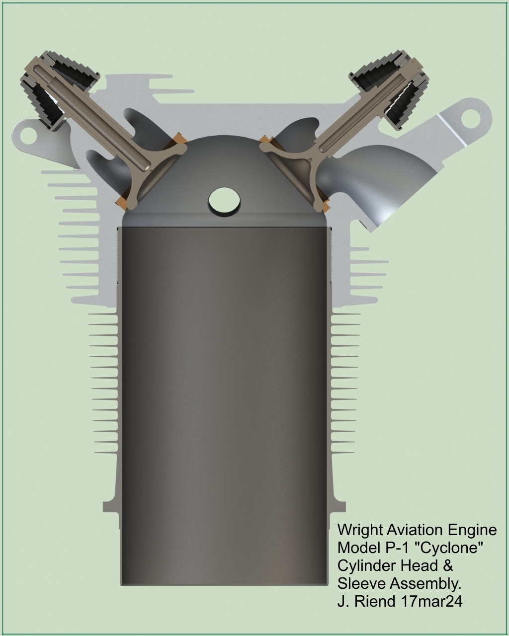 |
| Cylinder Head | Cylinder Head and Sleeve Assembly | ||||
 |
 |
 |
 |
 |
 |
 |
 |
 |
 |
 |
 |
 |
 |
 |
 |
 |
 |
 |
 |
 |
 |
 |
 |
 |
 |
 |
 |
 |
 |
 |
| Oil Pump Assembly | Oil Sump Assembly | ||
Send mail to
![]() with questions or comments about this web site.
with questions or comments about this web site.
![]()