|
|
 |
 |
|
|
|
|
|
|
 |
Superchargers allow an aircraft engine to develop more power at a given altitude by boosting manifold pressure, typically with a centrifugal compressor. This can achieve greater power for takeoff and climb, or maintain sea-level power to high altitudes. Supercharger compressors can be driven by the engine or by the energy that remains in engine exhaust gasses. Those driven by the engine are typically called superchargers; those driven by exhaust gasses are typically called turbosuperchargers, turbochargers, or turbos. Many variations have been produced, and even more have been tried. There are examples of multiple stage and multiple speed superchargers. There are combinations of turbochargers and superchargers. There are manual and automatic controls for all types. |
Superchargers
The Packard-Merlin Variable Speed Drive, by Jerry Wells
Test Report on the Szydlowski-Planiol Supercharger with Critique, by Jerry Wells
Turbosuperchargers
Turbosupercharger Control Systems: Part 1 — Oil Pressure
Turbosupercharger Control Systems: Part 2 — Electronic
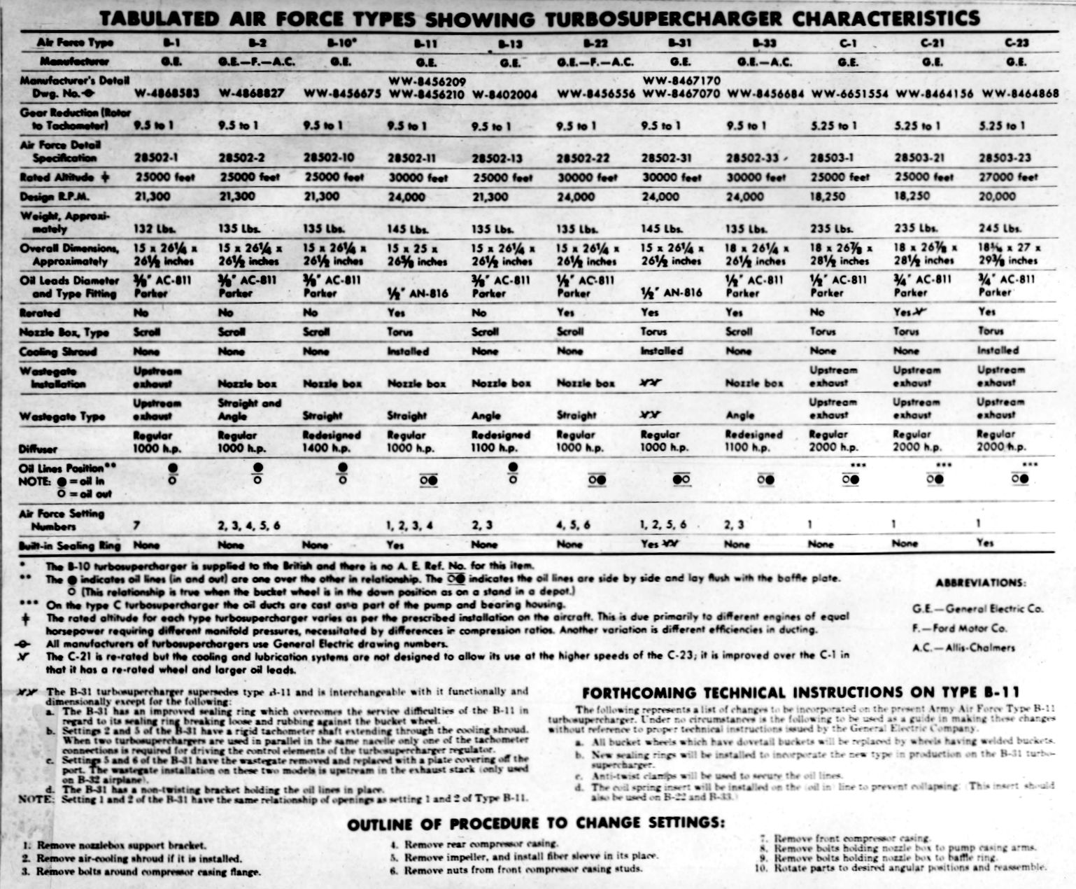
General Electric Turbosupercharger Data
Turbosuperchargers for Experimental USSAC Aircraft, circa 1942
The First Turbosupercharged U.S. Aircraft Engine
by Kimble D. McCutcheon
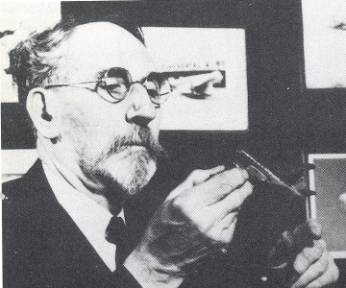 | Sanford Alexander Moss, the person most responsible for development of turbosupercharging in America, was born in San Francisco on 23 Aug 1872. At the age of 16 he got the idea that if fuel was burned in compressed air, its energy output could be increased. This idea followed him through his engineering training at the University of California to Cornell, where he wrote his 1903 PhD thesis on the gas turbine. After Cornell, Moss was hired by General Electric and worked on blast furnace centrifugal compressors at GE's West Lynn, Massachusetts plant. The National Advisory Committee on Aeronautics approached Dr. Moss with a request to find a way to give military aircraft more power. The resulting turbosupercharger (hereinafter turbocharger), developed with the help of the U.S. Army Air Corps, won Dr. Moss and the Army Air Corps the Collier Trophy in 1940. This story of the first turbocharged aircraft engine tested in the United States of America comes largely from Report No 558, by W.A. Reichle, Assistant Motor Testing Engineer, War Department Bureau of Aircraft Production, Airplane Engineering Division, Experimental Engineering Section at McCook Field, Dayton, Ohio. |
Introduction
Alfred Büchi (1879-1959), a Swiss research engineer at Gebruder Sulzer, patented a device using an exhaust-driven compressor to increase engine power in 1905. A Gernam named Schmidt patented a four-cycle engine turbocharger in 1911. A similar device was patented by August Rateau for aero engines in 1917, tested on a French mountain top, applied to a Renault aircraft engine, and probably flown. The National Advisory Committee on Aeronautics (NACA) learned of this, and asked General Electric to pursue U.S. turbocharger development in conjunction with the US Army Air Service.
Turbocharging the Liberty
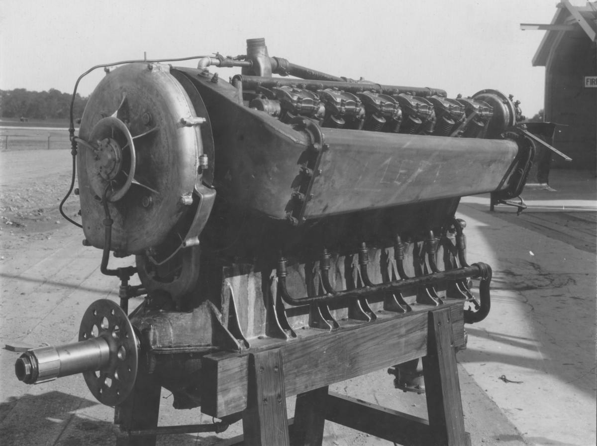
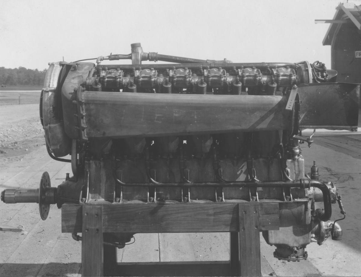
In preparing for its planned role in WWI, the US Army Air Service had ordered tens of thousands of 1,650 in³, 400 hp Liberty V-12s into production, and thousands had been built before all Liberty contracts were cancelled shortly after the Armistice was signed. Many of these were sold sold as surplus, but the Liberty 12 became the ubiquitous Army test engine for more than a decade.
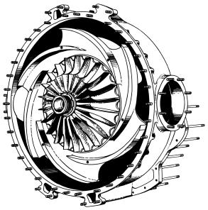
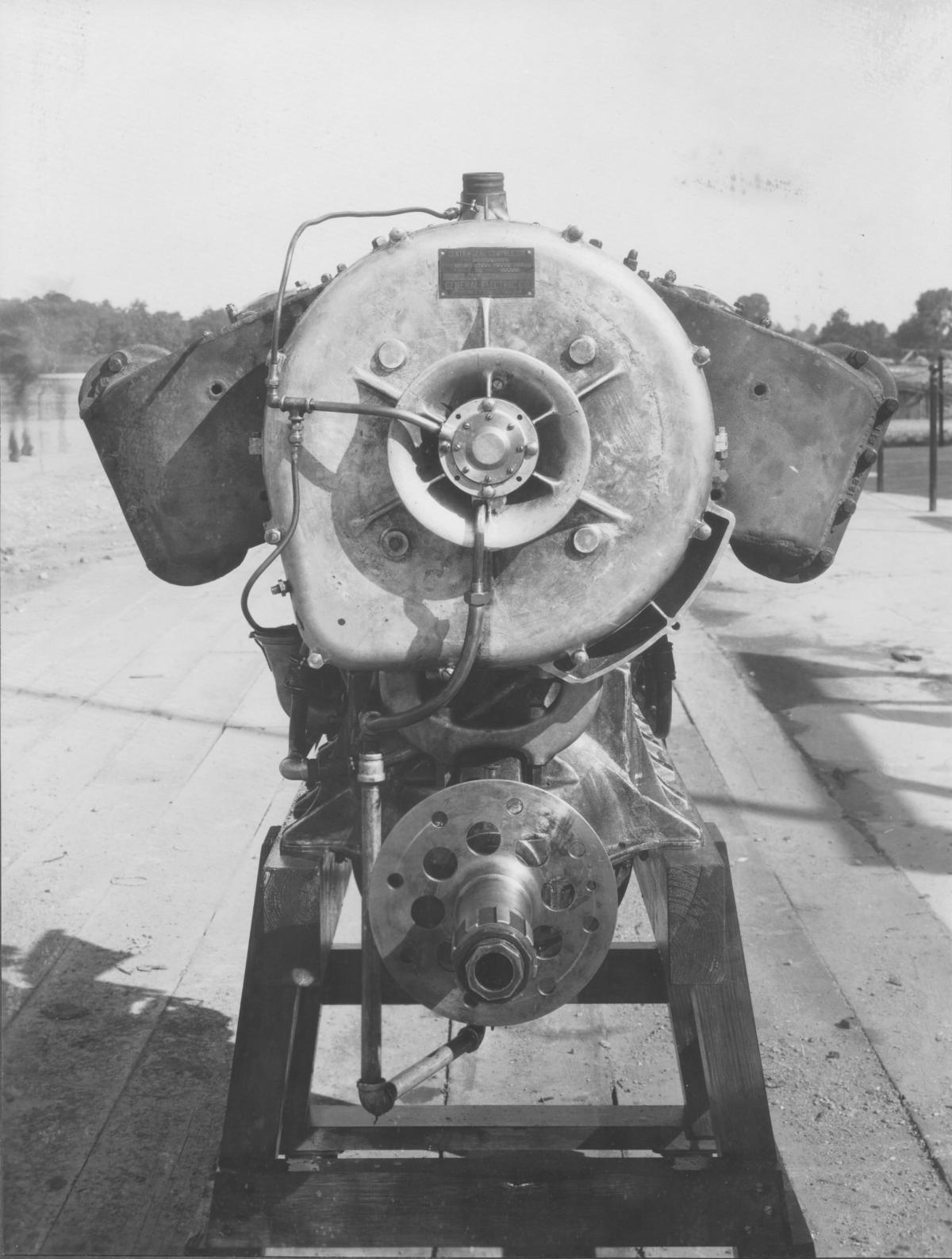
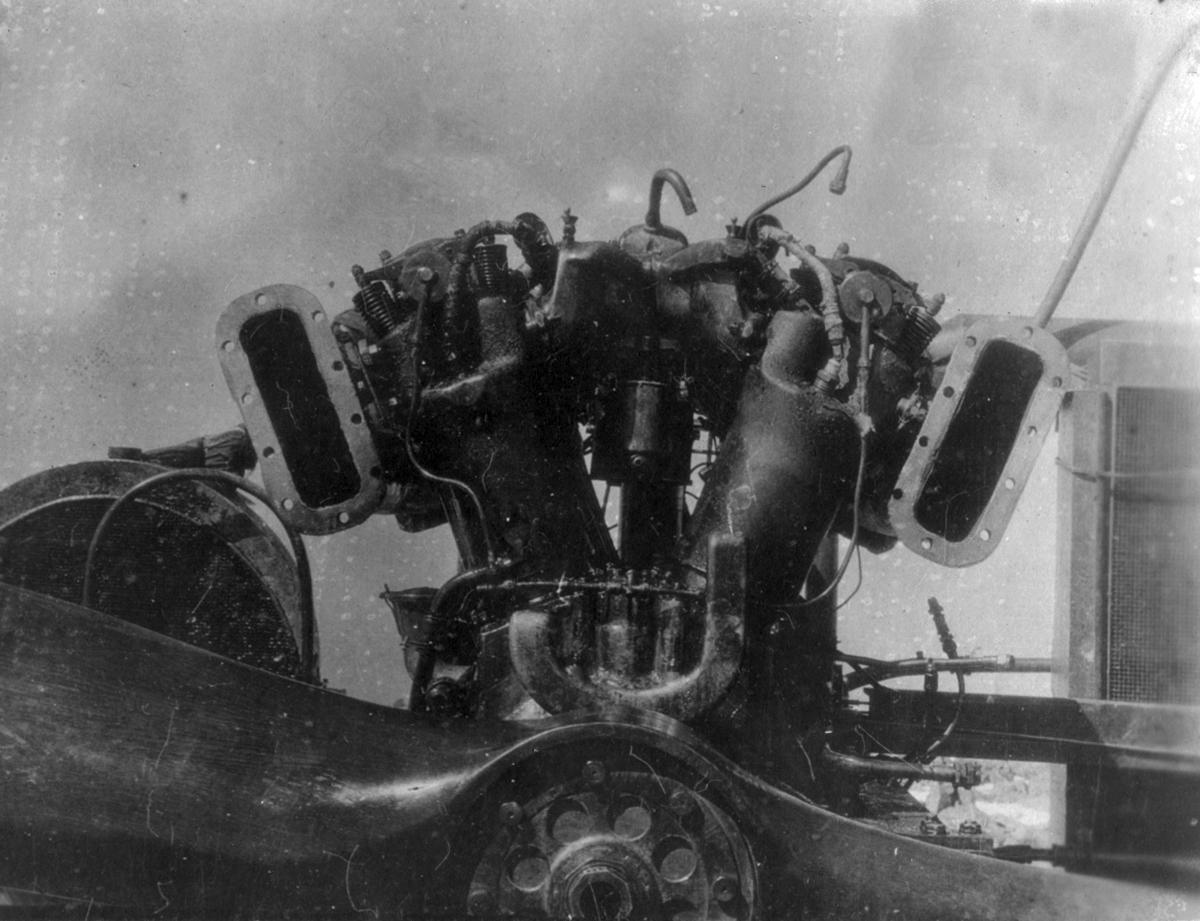
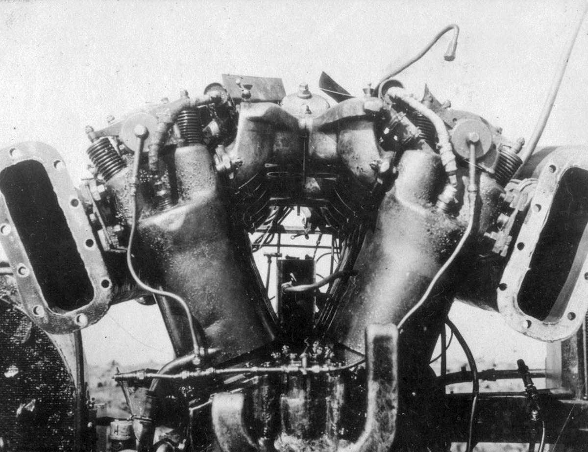
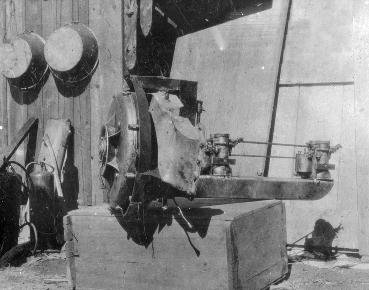
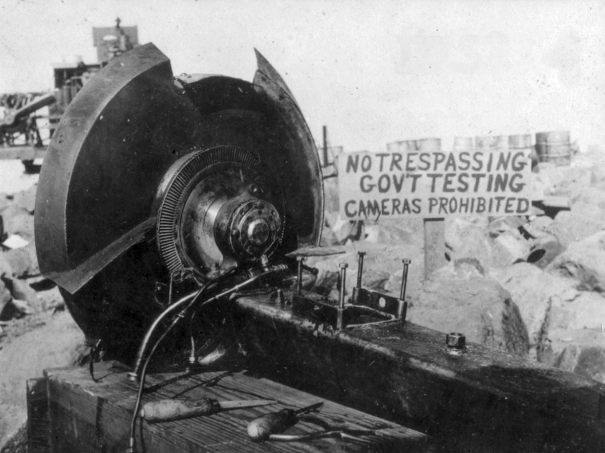
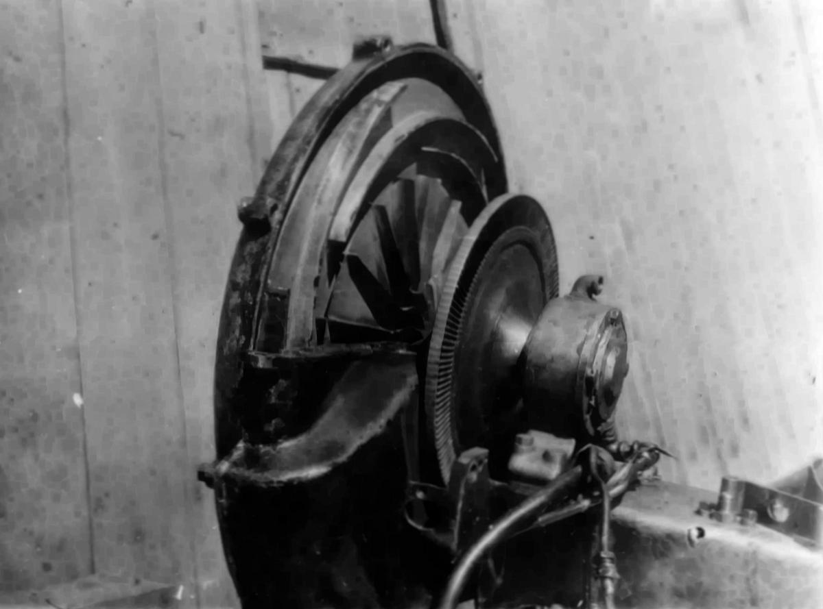
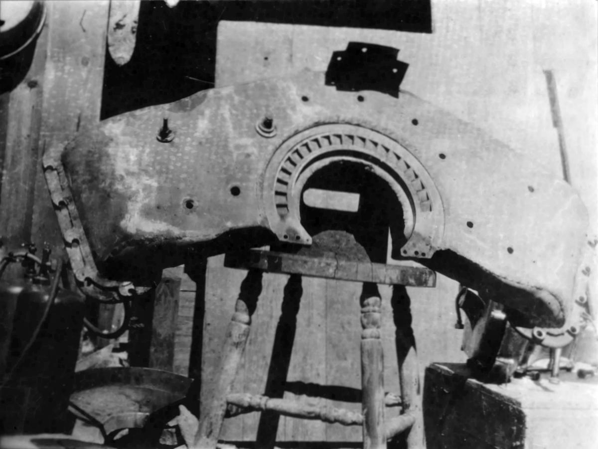
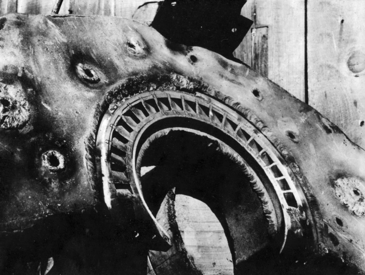
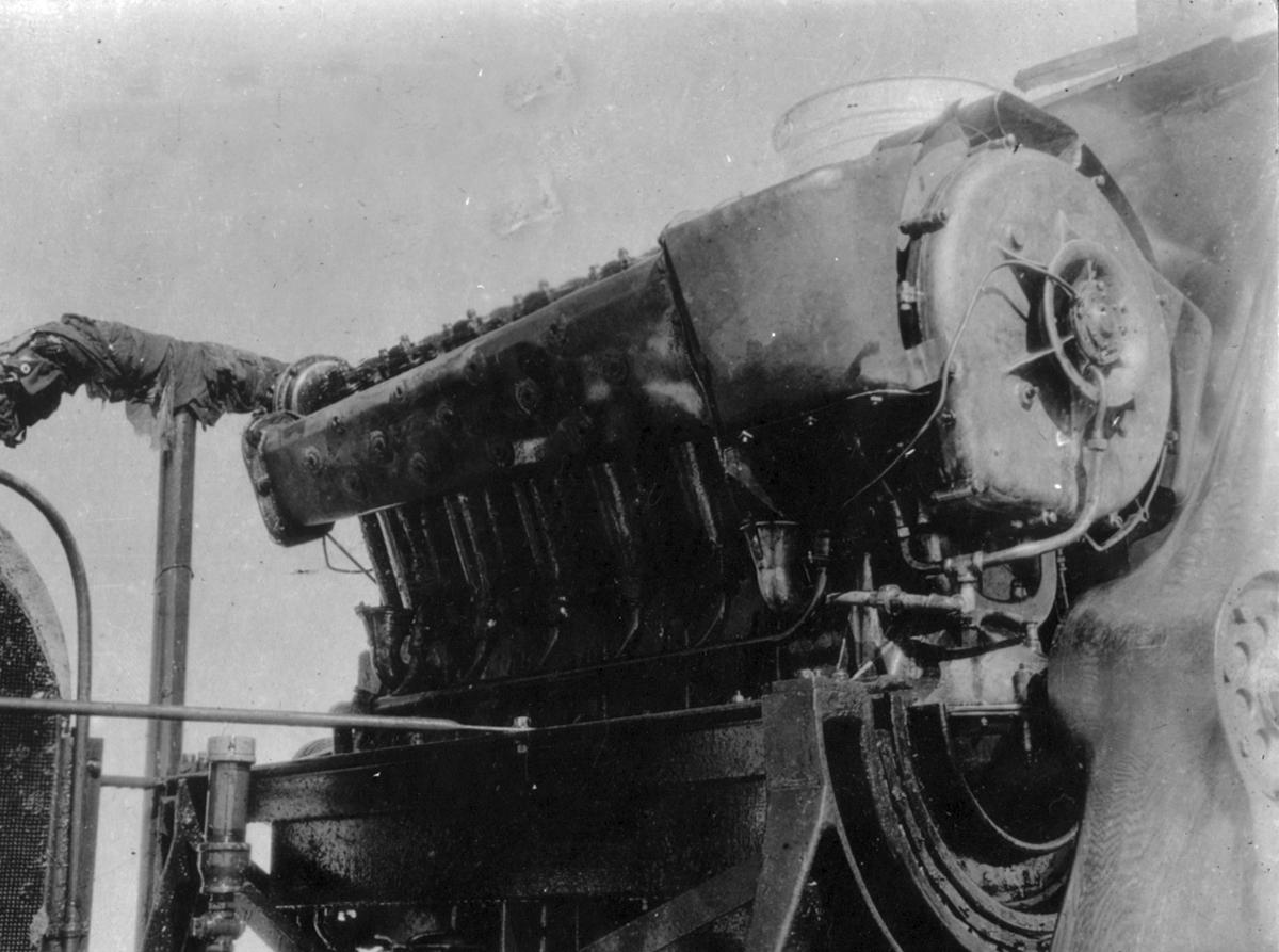
The Liberty turbocharger was designed and built by General Electric under Dr. Moss's direction. The turbocharger consisted of two rotors mounted on a single shaft with a bearing at either end. The turbine wheel, which was 10" in diameter, was spun by engine exhaust gasses and drove a centrifugal compressor impeller of about the same diameter. Engine exhaust gasses were routed through an exhaust manifold to a nozzle box containing nozzles that directed the gasses onto turbine wheel buckets where the exhaust energy was extracted. The turbine wheel discharged directly into the atmosphere. Nozzles covered only a portion of the turbine wheel's periphery. A system of baffle plates and ducts helped to withdraw exhaust gasses and ventilate the buckets. Slipstream air helped cool the exhaust manifolds and nozzle box.
The impeller received air from both sides through ducts fed by the slipstream. Compressed air was discharged from the bottom of the casing into a triangular duct running along the cylinder "V" to air intakes on the dual carburetors. Slipstream air helped cool the compressed air.
Oil from the Liberty engine oil system lubricated the front and rear turbocharger bearings, with drains leading oil back to the engine crankcase. The turbine wheel bearing was cooled by water from the Liberty cooling system, which completely surrounded the turbocharger lubricating oil chamber.
Waste gates at the ends of the exhaust manifolds allowed exhaust gasses to be wasted in order to decrease nozzle pressure and thereby regulate the amount of supercharging. Although automatic control of these waste gates was envisioned, manual control was used for initial testing.
Test Rigs
The GE turbocharger arrived at McCook Field on 4 Jun 1918. Liberty 12 No 59, US No 23466, was allotted for testing. Initial installation work was completed on 17 Jun 1918, and preliminary test runs were made on 19 Jun 1918. As the first object was to test and refine the turbocharger mechanical construction to withstand the high velocities and temperatures to which it was subjected, the turbocharger was not connected to the carburetors and no attempt was made to supercharge the engine.
Mechanical development continued until about 7 Jul 1918, at which time the engine and turbocharger were mounted on a cradle torque stand, and 470 hp at 1,700 rpm attained for about one minute. Testing with the turbocharger operating was difficult, because even with a small amount of supercharging at low altitude, spark plugs failed, along with numerous other difficulties.
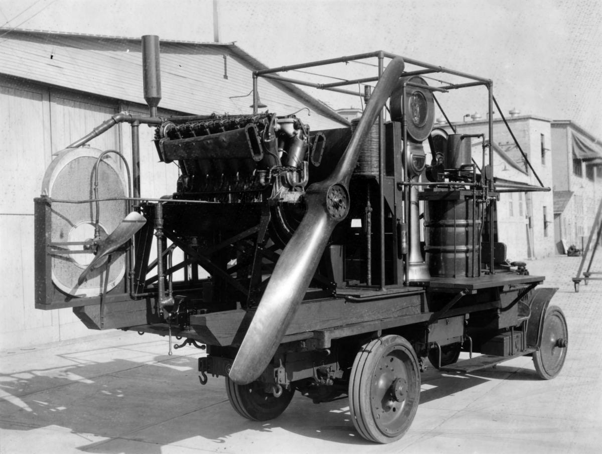
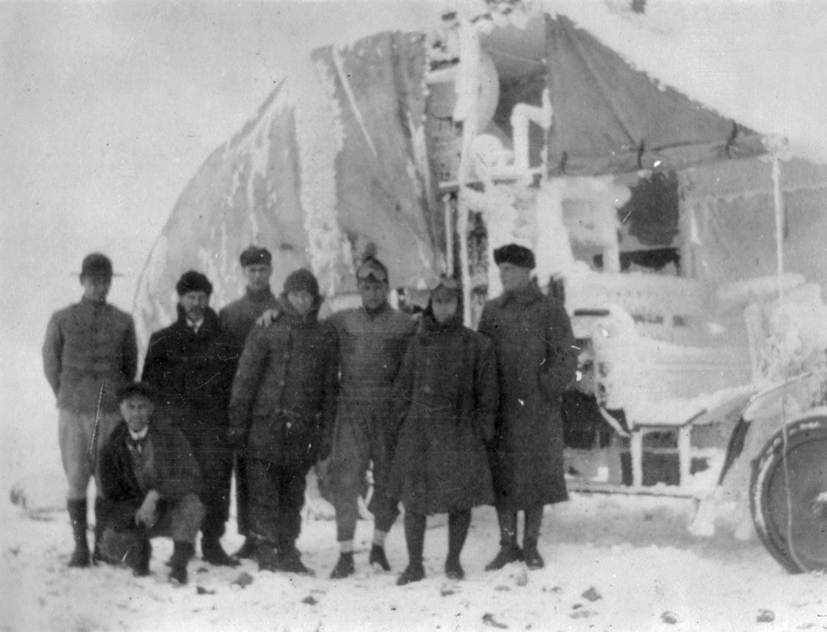
Despite the difficulties, early testing indicated that altitude tests were in order, and preparations were made to perform this altitude testing at Pikes Peak, Colorado. The Liberty engine with turbocharger was mounted on a cradle torque stand installed on a motor truck along with equipment and instruments necessary for complete engine testing. The test truck left McCook Field on 1 Sep 1918 and was driven to Pikes Peak, elevation 14,109'. Testing ensued at Pikes Peak from 10 Sep 1918 through 7 Oct 1918, under the direction of Dr. Moss and Mr. C.P. Grimes of the Airplane Engineering Division.
Instrumentation
A barometer provided by the U.S. Weather Bureau gave the actual atmospheric pressure for each test so that the elevation was never used.
A small elevated gasoline header tank was supplied during engine runs by manual operation of a three-way cock supplied from a lower, larger gasoline tank on which air pressure, supplied by a propeller air pump, was maintained. An auxiliary hand pump was also provided. A standard Liberty 12 Lunkenheimer primer supplied fuel to the intake manifold. Ether was used for starting.
A 10-gallon elevated oil tank supplied caster oil to the engine.
Testing
The turbocharger was first tested with steam at the General Electric Works at Lynn, Massachusetts. It was then installed on a Liberty 12 at McCook Field and tested on a dynamometer stand. At that time the ventilator system was absent and no results were obtained beyond demonstration that the apparatus was operative. The engine/turbocharger combination was fitted with a propeller and installed in a wind tunnel on a cradle dynamometer to analyze circulation and ventilation. However, atmospheric pressure was so great that even a small amount of supercharging caused serious preignition, making it possible to obtain only a small increase in power for a very short time.
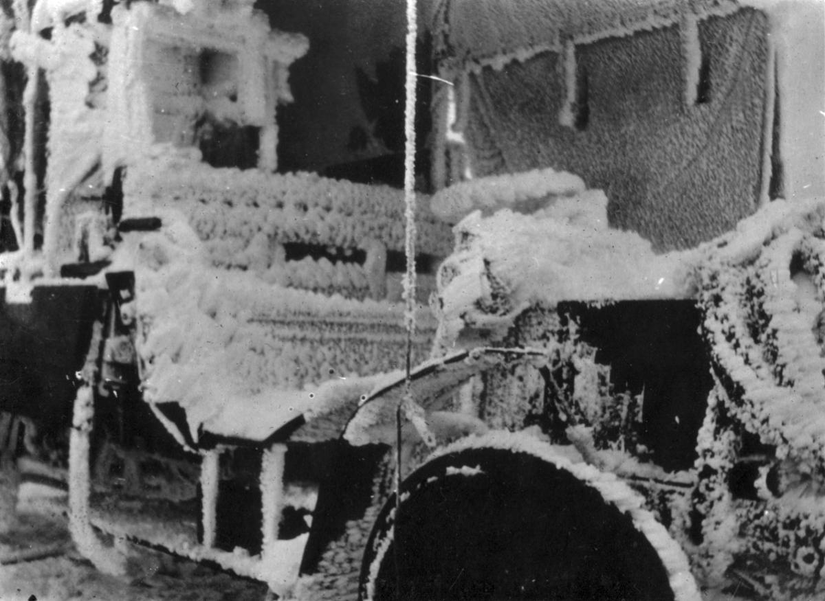
At Pikes Peak Summit, turbocharger operation was reasonably satisfactory. Two thrust washers, made of a highly hardened steel, broke. These were later changed to bronze and performed well. Stay bolt reinforcements, acetylene welded to exhaust manifolds and nozzle boxes, pulled out. This was traced to faulty welds. The old stays were repaired and additional stays were added to stiffen the nozzle plate. Just prior to the endurance run a piece of the aluminum compressor casing was discovered to have broken away. A temporary repair was made, but some leakage remained. Early Summit tests experienced trouble with exhaust joint gaskets, which was addressed through the use of mobiline gaskets set in red lead running against carefully faced joints. Soft copper gaskets were also effective.
Tests at the Summit showed that it was possible to raise the mean effective pressure of the Liberty to practically the same value obtained at sea level. It was possible to exceed this value at lower altitudes, but preignition limited the practicality of this. Tests at McCook field with the same Liberty 12 used at the Summit gave 346.5 hp at 1,775 rpm. This corresponded to nearly 354 hp at 29.92 inHgA and 1,890 rpm, but these corrected figures had some uncertainty due to windage on the engine and cradle dynamometer from the propeller spiral slipstream.
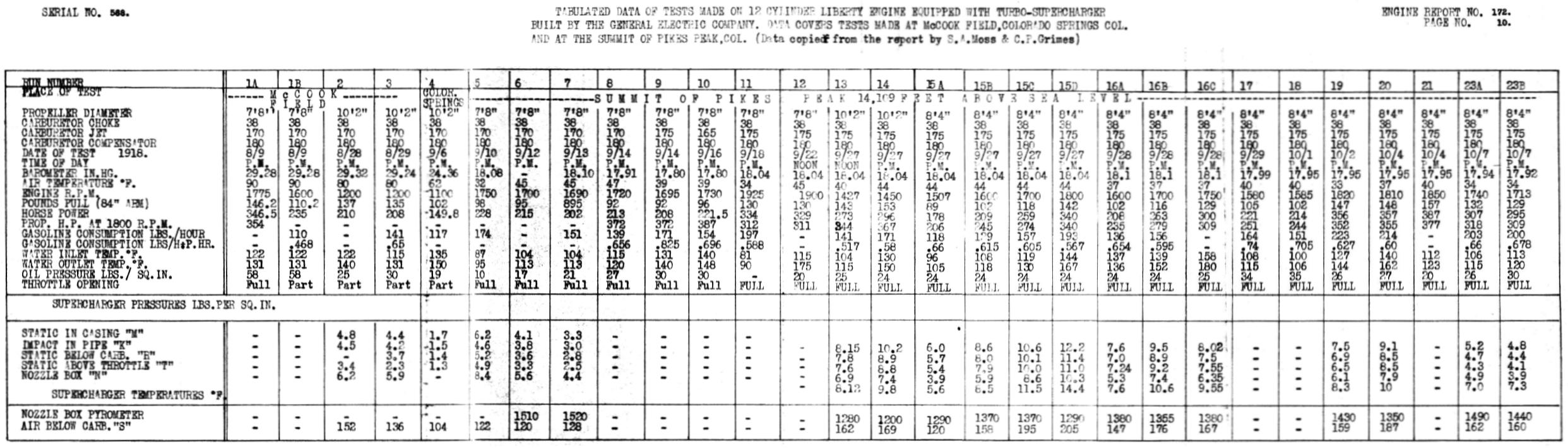 |
| Results of Turbocharged Liberty 12 Test Runs |
Test Conditions
Runs 1A, 1B – Made at McCook Field without turbocharger to establish an average performance near sea level.
Runs 2, 3, 4 – Made with the turbocharger on the engine to check apparatus performance, but exhaust gates were used and no quantitative data was collected. These runs were affected by a clogged carburetor jet.
Runs 5, 6, 7 – First tests at Pikes Peak Summit. Run 5 gave such a low result that the exhaust manifold was covered with insulation for runs 6 and 7, with no improvement. Trouble again was with clogged carburetor jets.
Runs 8, 9, 10 – Tests with various carburetor settings and without turbocharger. Altitude control set for best performance.
Run 11 – With turbocharger and throttle wide open. Exhaust gaskets blew.
Run 12 – With turbocharger and mobiline exhaust gaskets with red lead. Exhaust gates closed, throttle partially open.
Run 13 – Changed to a large propeller due to high speed of previous runs. Exhaust gates closed, throttle partially open.
Run 14 – Check test with same conditions as run 13.
Runs 15A, 15B, 15C, 15D – With turbocharger and exhaust gates closed. An intermediate propeller was used to achieve about 1,800 rpm. Each test opened the throttle more, with it being nearly open during 15D.
Runs 16A, 16B, 16C – Check tests on runs 15A ~ 15D. Highest speed runs in both cases gave excessive preignition and spark plug trouble.
Runs 17, 18 – Without turbocharger, altitude adjustment set for best performance.
Run 19 – A 0.75 hr run representing the results of all experience with the apparatus.
Run 20 – Check on run 19. Runs 19 and 20 produced the maximum power that could be maintained within preignition limits.
Run 21 – Maximum power that can be obtained with the turbocharger opened to the limit. This condition could only be maintained for about 30 seconds before spark plugs failed.
Run 23A, 23B – Conditions slightly less severe than Runs 19 and 20. These runs covered 4:22 hrs.
Exhaust gas and turbine temperatures never rose to troublesome levels, and all parts except the nozzle box were always below a visible red. Preignition was experienced when the nozzle box just reached visible red.
The two best runs obtained at Pikes Peak Summit were runs 10 and 19, which are tabulated below.
| Test 10 Without Turbocharger |
Test 19 With Turbocharger |
|
|---|---|---|
| Inlet Water, °F | 140 | 127 |
| Outlet Water, °F | 148 | 144 |
| RPM | 1,730 | 1,820 |
| Horsepower | 221.5 | 356 |
| Fuel, lb/hr | 154 | 223 |
| Fuel, lb/hp/hr | 0.696 | 0.627 |
If power output of the run with turbocharger was reduced to the same rpm as the run without turbocharger, the resulting power would be about 340 hp, which means that an increase of about 118.5 hp was achieved by using the turbocharger.
Evaluation
The Liberty 12 weighed approximately 867 lb and produced 0.2555 hp/lb at 14,109'. The turbocharger with its attendant manifolds, extra radiator, extra water, stronger gasoline header tank, etc., added about 310 lb, bring the total weight of the turbocharger Liberty to 1,177 lb, but it produced 0.289 lb/hp, a slight improvement.
Reichle observed that considerable difficulty would be encountered if the turbocharged Liberty were installed in an airplane. He noted that the nose radiator would have to be relocated and substantially enlarged, all of which would increase the amount of power required to overcome the parasite drag. A means of positively controlling the turbocharger would have to be developed, and controls installed in both cockpits of two-place aircraft. A variable-pitch propeller would be required to take advantage of the increased power available at altitude, further increasing weight. Additional fuel capacity would also have to be accommodated. Fire protection would have to be added to insulate wood and fabric aircraft components from the 1,400 ~ 1,500°F exhaust components.
Reichle opined that a larger engine would be a simpler and lighter way to achieve the same result. But as we know, work continued on perfection of the aircraft turbosupercharger. All of Reichle's objections were addressed and turbochargers became standard equipment in Boeing B-17s, Boeing B-29s, Consolidated B-24s, Lockheed P-38s, and Republic P-47s, all of which were produced in large quantities during WWII.
 |
 |
 |
 |
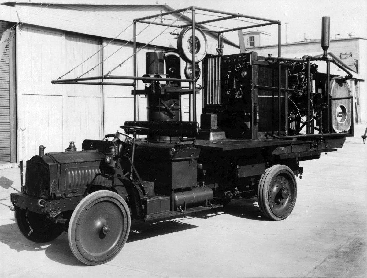 |
| Liberty 12 with Turbocharger | Liberty 12 with Turbocharger | Liberty 12 with Turbocharger | Turbocharger Test Rig | Turbocharger Test Rig |
 |
 |
 |
 |
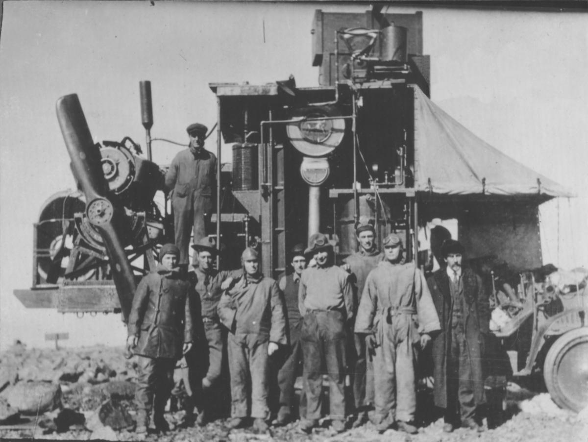 |
| Turbocharger Test Rig | Arrival at Colorado Springs | Morning at Pikes Peak Summit | Testing | 4-hr Test Complete Dr. Moss is at far right. |
 |
 |
 |
 |
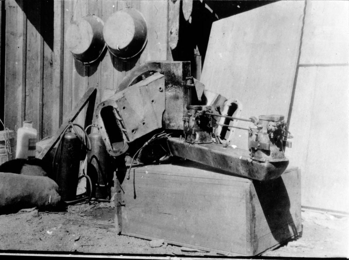 |
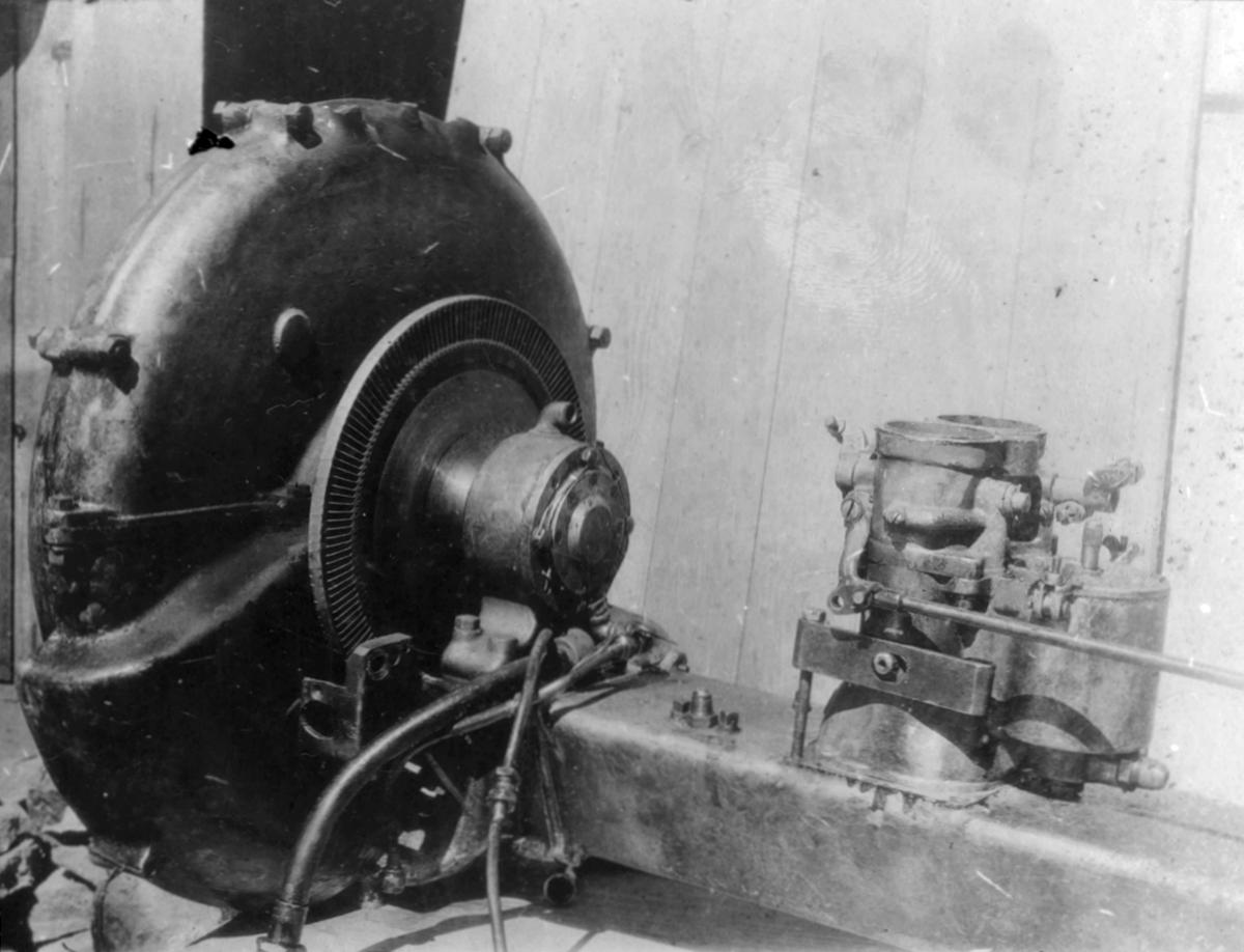
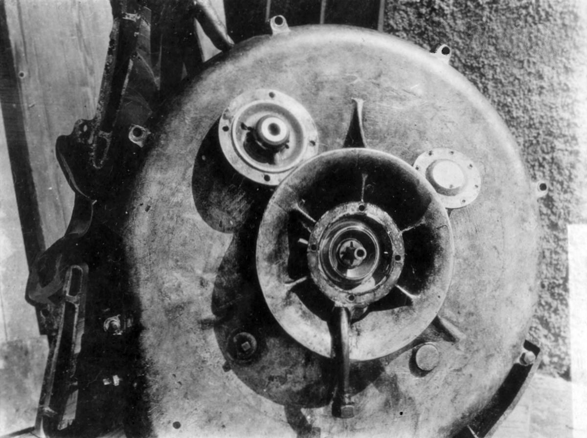
| Turbocharger Partially Removed | Turbocharger Removed | Intake and Exhaust Manifolds | Turbocharger and Carburetors | Turbocharger and Carburetors |
 |
 |
 |
 |
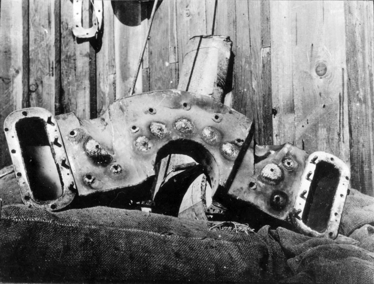 |
| Nozzle Box Removed | Deflector Plates Removed | Turbine Wheel and Impeller | Compressor Inlet Showing Thrust and Radial Bearings |
Nozzle Box Entrance Side |
 |
 |
 |
 |
 |
| Nozzle Box Exit Side | Detail Showing Nozzles | After a Stormy Night | Snow Covered Test Rig | Ready to Run |
Send mail to
![]() with questions or comments about this web site.
with questions or comments about this web site.
![]()