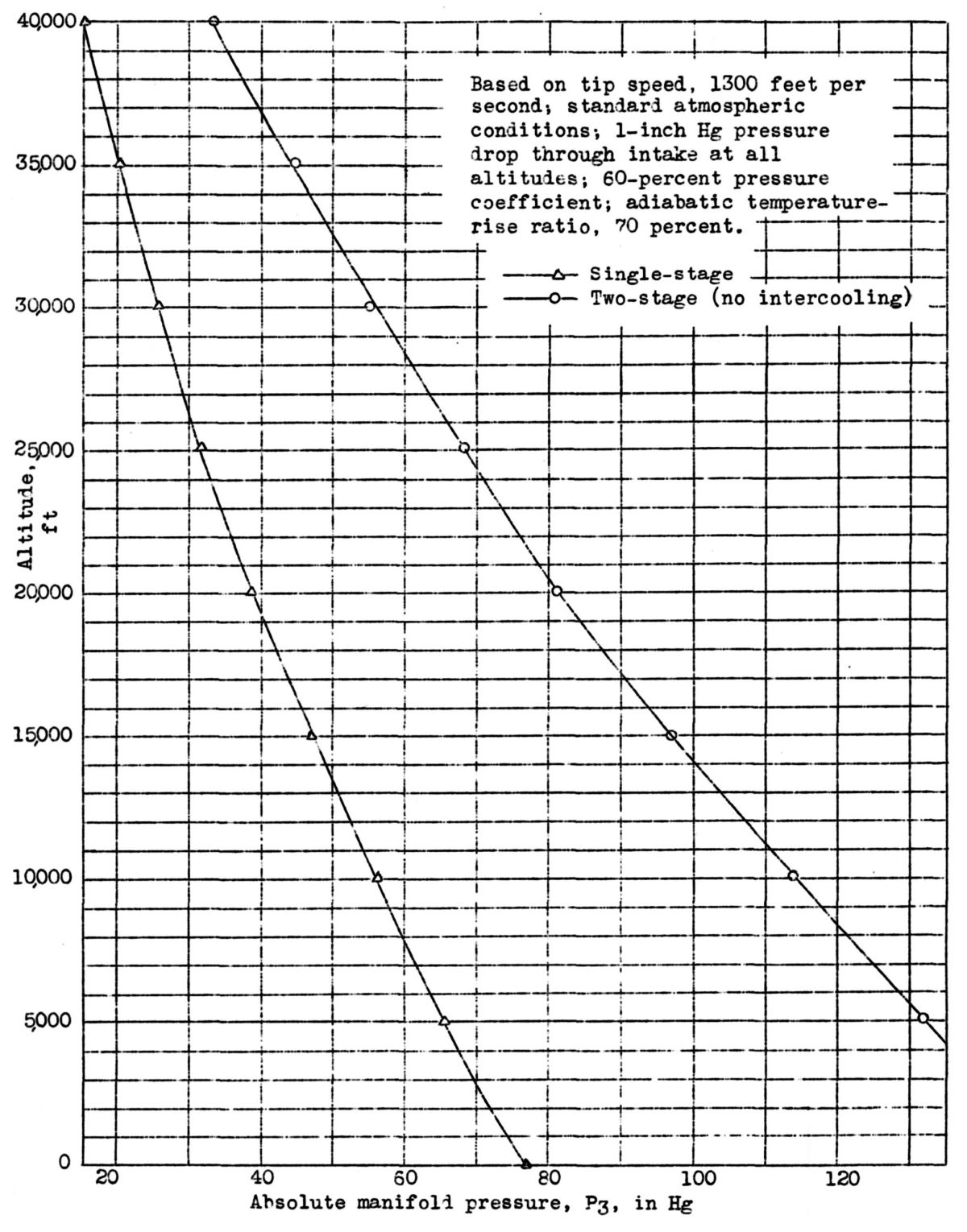
Fig. 1. Maximum Altitude Attained with Present Single-Stage and Two-Stage Superchargers
Two-Stage Supercharging
from National Advisory Committee for Aeronautics Technical Note No. 794
by Richard S. Buck, Pratt & Whitney, 15 Sep 1940
Originally Published by the NACA Feb 1941. Published by the AEHS 1 Mar 2021
| The arrangement of the parts and the installation and control problems of two-stage mechanically driven superchargers for aircraft engines are discussed. Unless an entirely new form of supercharger is developed, there will be a definite need for a two-stage centrifugal supercharger. It is shown that the two-stage mechanically driven supercharger itself is a comparatively simple device; the complications arise from the addition of intercoolers and controls. |
Introduction
Fig. 1. Maximum Altitude Attained with Present Single-Stage and Two-Stage Superchargers |
Flight at higher altitudes has become a definite trend. The pressurized cabin for transport airplanes has removed the limit on altitude that results from passenger discomfort; military airplanes are being forced to go ever higher to maintain air supremacy. In aircraft-engine design modern fuels permit the use of increased power by increased rotational speed and supercharger boost. The more the engine is boosted to make its rated power, the lower will be the critical altitude of the supercharger. The combination of higher altitudes and more boost means that the supercharger will be called on to do much more work than in present-day design.
Because so few fundamental facts are known about the compressor, the future limitation of a single-stage compressor cannot be predicted. It is a known fact that there is a marked tendency for the compressor efficiency to fall off at tip speeds greater than 1,300 feet per second (fps). The approximate limit of current supercharger performance when running at tip speeds of 1,300 fps is shown by the lower curve of Figure 1 in which the maximum attainable altitudes are plotted against manifold pressures. Manifold pressures greater than 50 inHgA are allowed on some of tae present aircraft engines for take-off and short periods. The curve indicates that an altitude less than 14,000 feet is all that can be attained with a single-stage supercharger under these conditions.
When higher altitudes are desired, another stage of supercharging must be added in series with the first stage; the resulting combination is a two-stage supercharger. With each impeller operating at a tip speed of 1300 fps, the-two-stage supercharger can deliver the performance shown by the upper curve of Figure 1. The altitude limit is raised from 14,000 to 32,000 feet at a manifold pressure of 50 inHgA. The values shown on both curves are based on certain arbitrary assumptions that are open to some controversy because improvements in supercharger performance are continually being made. A much greater increase in efficiency than is believed possible at the present time would, nevertheless, be required to increase materially the altitude limitations of the centrifugal supercharger.
Two-Stage Superchargers
Many factors have to be considered in the choice between single-stage and two-stage superchargers. Engine power is controlled by the manifold density rather than the manifold pressure so that either power or critical altitude can be increased with either single-stage or two-stage arrangements by the addition of intercoolers. Intercoolers increase drag and weight and multiply installation problems, but if installed between stages, intercoolers also decrease the power required to drive the second stage. There is no definite altitude above which a two-stage supercharger must be used for best airplane performance and, for a range of about 3,000 feet altitude above or below the limits of a single-stage supercharger, the choice is a very difficult one. If maximum airplane performance is demanded above this altitude range, however, a multistage supercharger must be used.
The first stage of a two-stage supercharger may be driven either by an exhaust, turbine or mechanically by the engine through gearing. Most of the problems relating to the superchargers themselves are the same for both types and the relative merits of the drive type will not be discussed. Both types take energy from the engine and any comparison should be based on which type utilizes this energy more efficiently in propelling the airplane. The final comparison is complicated by the fact that the turbine-driven supercharger takes little power from the engine and the mechanically driven supercharger leaves more energy in the exhaust for jet propulsion.
General Classifications
The most common two-stage supercharger arrangements will be described with reference to the foregoing three factors.
Air Passage Arrangement
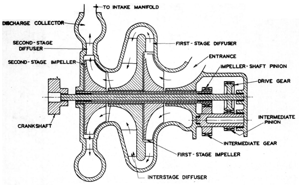 Fig. 2. Simple Two-Stage Supercharger |
Supercharger air passages are part of the engine induction system and the terms "air passage" and "induct ion system" may be used interchangeably. The induction system may contain air or a mixture of air and fuel and may be called either the "mixture" or the "charge." The engine air is drawn into the induction system and becomes the mixture or the charge after the fuel is injected into it. In the following paragraphs, however, either the mixture or only the air will be termed "engine air" to simplify the description of the various supercharger arrangements.
One of the simplest forms of two-stage superchargers is the conventional type shown in Figure 2. Air enters the first stage, is compressed by the impeller, and its energy is partly transformed from kinetic to pressure energy in the diffuser. The air has to flow over a lip before entering the second-stage impeller and, because of this action, the term "cascade" has been suggested for this type of supercharger. The air passage from the first stage diffuser to the entrance of the second-stage impeller is sometimes made a continuation of the first-stage diffuser.
Engine air leaving the supercharger second-stage discharges either into a collector chamber or into scrolls, depending upon the type of engine employed. Radial engines require collectors because intake pipes are used for each one or two, cylinders. Scrolls may be used where discharge is into manifolds in which the flow is comparatively steady. The fuel may be introduced by a carburetor located either at the entrance to the first stage in the same manner as with a single-stage supercharger or between the second-stage discharge and the engine cylinders. There is insufficient room for intercoolers between the two stages, but intercoolers may be located between the second-stage discharge and the cylinders. In this type of installation the fuel is normally injected into the engine air after the intercoolers in order to avoid passing the fuel through the intercoolers.
In two-stage superchargers designed for radial aircraft engines it is generally inconvenient to provide intercooling between the second-stage supercharger and the cylinder intakes. Intercoolers are therefore installed between the first and the second stages. Less heat is removed from the engine air by intercoolers installed in this location than when they are installed after the second stage because the temperature difference between the cooling air and the engine air is less. This shortcoming is partly redeemed by the fact that the power required to compress a given amount of air is proportional to its absolute temperature; cooling the air ahead of the second-stage supercharger therefore reduces the power required by this supercharger. If weight were of no importance, the highest engine power would be obtained by installing intercoolers in both places, that is, between the first and the second stage and after the second stage. Such an arrangement is considered impracticable at the present time because of the weight and the installation problems involved.
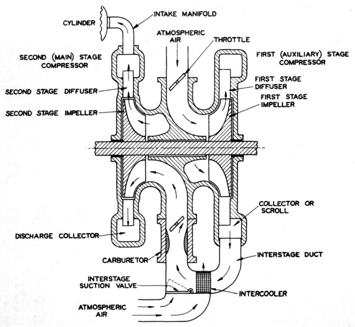 Fig. 3. Two-Stage Supercharger with Segregated Stages |
Figure 3 is a diagram of a supercharger with separated stages, which is the type usually used on radial engines. In the cascade type air leaving the first stage discharges directly into the second stage, whereas with the separated type the first stage discharges into a duct permitting the use of intercoolers between the two stages. The impellers may be placed front to front, an arrangement that, as shown by the diagram, permits a somewhat more compact arrangement of inlet passages than the cascade type and saves some overall length. The first stage of this supercharger is sometimes called the auxiliary stage because it may operate independently of the second stage, which is adjacent to the engine. Air leaving the auxiliary stage is led through ducts to the intercooler. When it leaves the intercooler the air is conducted to the carburetor, which controls the injection of fuel and is usually located just ahead of the supercharger second stage.
The supercharger second stage is sometimes called the main stage because it may function alone in the same mariner as the supercharger of a single-stage engine. Either one or two intercoolers may be used, depending upon the number of outlet connections from the auxiliary stage supercharger. If two intercoolers are used air from each intercooler can be merged just ahead of the carburetor.
The arrangement of air, passages may be the same with the exhaust turbine-driven supercharger as with the auxiliary supercharger just described. The chief difference between the two types is in location, the exhaust-driven impeller usually being located with the axis of its shaft at right angles to that of the engine.
With the separated supercharger arrangement it may be desirable to shut off the first stage during low altitude operation. It is then necessary to take the engine air from between the two stages through inwardly opening suction valves as shown in Figure 3 because, with an impeller at rest or turning slowly, considerable air pressure loss will occur when the quantity of air necessary for normal power is taken through the impeller and the diffuser passages. These suction valves will open at any time that the atmospheric pressure exceeds the-pressure inside the engine-air passages, and this condition will usually occur when the first-stage supercharger is turned off or throttled. Under these-conditions the engine operates as though it had only a single-stage supercharger. Suction valves also act as relief valves to prevent the interstage ducts from collapsing when the first-stage valves are closed.
Drive Method
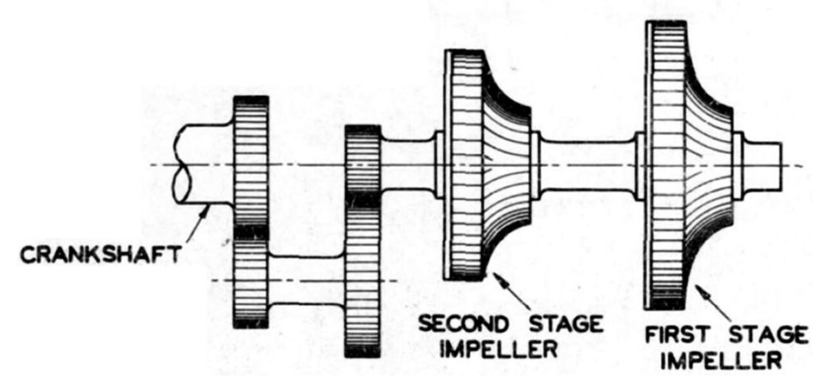
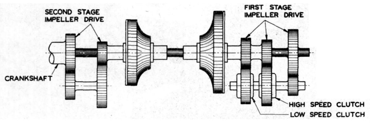
The two supercharger impellers may both be mounted on the same shaft or each may be mounted on a separate shaft. In either case, the impellers must be driven at speeds between 6 and 12 times crankshaft speed. This high speed is usually obtained through step-up gearing from the crankshaft, and clutches may be used to vary the speed as desired. Figure 4(a) shows two impellers mounted on the same shaft and driven by gearing from the end of the crankshaft. Figure 4(b) shows a diagram of an arrangement whereby the impellers are mounted on separate shafts, each driven by its own gearing. The first-stage impeller is driven through clutches that provide two speeds and a neutral position. The purpose of this arrangement is to reduce the power required to drive the first-stage supercharger when it is not needed. The second-stage impeller is driven from the crankshaft through fixed-ratio gears. With the first stage in neutral, engine air is obtained through the suction valves located between the two stages, as previously mentioned.
The ideal form of supercharger drive is one permitting an infinitely variable speed without the necessity for sudden shifts from one speed to the next. With this drive; the impeller turns only fast enough to supply the air compression required by the engine. There are several definite advantages of the variable-speed drive: First, owing to its lower speed, it reduces the power required to drive the supercharger when below its critical altitude; second, it lowers the discharge temperature for the same reason; and, third, it simplifies the engine controls, as will be described later. It can be used to good advantage on the single-stage, the cascade-type of two-stage, or the first stage of the separated type of two-stage supercharger. The mechanical difficulties involved in developing a successful variable-speed drive to transmit several hundred horsepower and still be light enough for installation in an aircraft engine can be imagined. There are reports of this work being done, however, so it is probable that it will become a standard installation in the near future.
The first-stage supercharger may also be driven by an exhaust turbine, which gives an infinitely variable speed as controlled by the exhaust waste gate position. Proposals have been made for positively controlling the speed of the exhaust-driven supercharger by gearing it to the engine but, as far as is known, no such installation has ever been made on an aircraft engine.
 |
 |
| Fig. 4a. Impellers Mounted on Common Shaft | Fig. 4b. Impellers Mounted on Separate Shafts |
Induction-Air Control
The pilot can change aircraft engine power either by changing the engine speed or the density of the air in the manifold. The engine speed can be controlled by the propeller governor and the manifold pressure can be controlled by the throttle. The control of the engine speed by means of the governor is not suitable for quick power changes because the propeller pitch change is too slow and because the complete power range from idle to full power cannot be covered by means of changing pitch. Therefore the pilot selects the engine speed for any type of operation and changes power by means of the throttle.
Engine power is affected both by manifold pressure and manifold temperature, and it is quite a problem to keep these factors at the desired values under different flight conditions. Manifold pressures and temperatures may be affected by supercharger speed, atmospheric temperature, altitude, ram, and throttle position.
With the exception of throttle position, it is desirable to control all off these factors automatically because so doing relieves the burden on the pilot. Automatic control also prevents him from accidentally opening the throttle to such an extent that an excessively high manifold pressure or temperature is produced, which may damage the engine by overpower or detonation. In order to obtain the most economical operation with most types of airplane, it is desirable to hold the engine power at definite values. These values are determined by the type of operation desired.
In airplanes that are highly maneuverable, such as pursuits or fighters, the power may be continually varied over wide ranges; and, in these cases, it is desirable merely to restrict the maximum power to some safe value. It is therefore obvious that the higher the potential supercharging, the more necessary it is to provide automatic control.
There are innumerable ways of automatically controlling the manifold pressure. Most of these controls contain bellows that are sensitive to changes in pressure. These bellows operate a servomechanism, which in turn operates a throttle valve. On a single-stage supercharger or on a two-stage supercharger of the simple cascade type where the carburetor is placed ahead of the supercharger, the automatic control may act on the throttle valves located in the carburetor. In this type of control the pilot sets the cockpit control to give a certain desired pressure. The automatic control then operates the carburetor throttles to give the pressure selected.
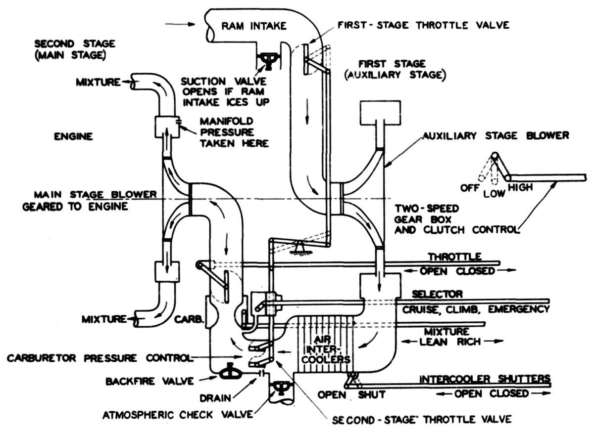 Fig. 5. Two-Stage Supercharger with Automatic Power and Mixture Control<br />(Pratt & Whitney Design) |
Another method of power control is attained by installing automatically controlled valves ahead of the carburetor. This system is employed by the Pratt & Whitney Automatic Power and Mixture Control and may be used with carburetors that have no compensation for variations in pressure and temperature. The diagram of a two-stage supercharger employing this control is shown in Figure 5. It can be readily seen that a considerable variation in pressure and density is possible in the air duct containing the between-stage suction valve. When this valve is opened, the pressure in the duct varies with changes in atmospheric pressure and, without the automatic control valves ahead of the carburetor, this action would upset the carburetor metering-as well as change the engine power. The control .unit may be provided with a selector valve to permit the pilot to choose the combination of pressure and fuel flow desired. For take-off, a high pressure and a rich mixture are desired; whereas, in cruising, a lower pressure and a leaner mixture may be necessary. The carburetor mixture may be coordinated with the selection of pressure by means of fuel jets opened and closed with the selector valve.
The operation of a two-stage supercharger equipped with automatically controlled throttle valves ahead of both the first-stage and the second-stage supercharger will be explained by reference to Figure 5. The first stage throttle valve is located immediately ahead of the first or the auxiliary stage, and the second stage throttle valve is located immediately ahead of the carburetor. A bellows sensitive to the pressure at the carburetor entrance operates a floating piston through an oil servomechanism. This piston operates both the first-stage and the second-stage throttle valves as follows: With the piston at the bottom of its travel, both valves would be closed. At low altitudes, the valve ahead of the first-stage is closed and the valve ahead of the second stage is regulating the pressure at the carburetor entrance. As altitude is increased, the second-stage throttle valve opens and, when it is wide-open, the critical altitude of the second-stage is reached. As altitude is further increased, the first-stage valve starts to open and, if the first-stage supercharger is operating, the inwardly opening interstage suction valve will automatically close as soon as the pressure inside becomes greater than the pressure outside. The next critical altitude is attained when the first-stage valve is wide open. If the first-stage supercharger is shifted to a higher speed, the first-stage valve will partly close to keep the pressure at the carburetor' entrance at the same constant value.
The pressures ahead of a modern aircraft carburetor do not have to be maintained at a constant value to get correct fuel metering because the carburetor contains automatic mixture control-to compensate for air flow variations. Therefore, the second-stage throttle valve ahead of the carburetor can be eliminated, and the pressure ahead of the carburetor will be controlled by the first-stage valve except when the interstage valves are open. Under these conditions the pressure at the carburetor entrance will be governed by atmospheric conditions.
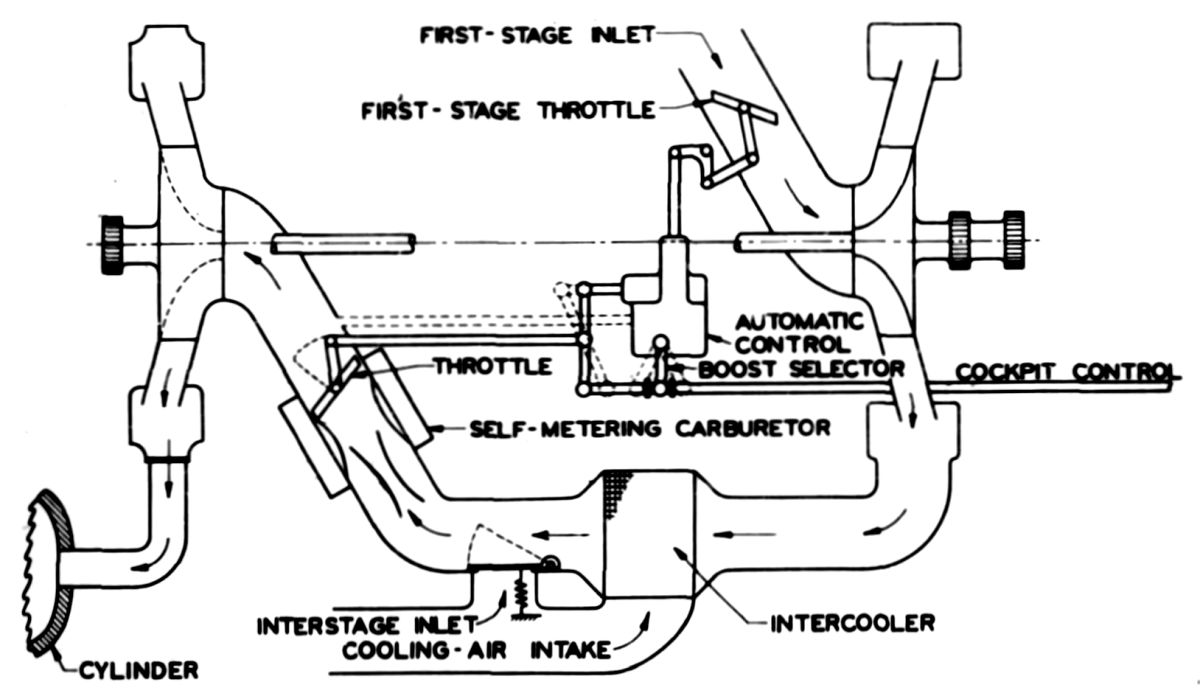 Fig. 6. Automatic Controls with Self-Metering Carburetor on Two-Stage Engine |
Automatic control, if desired, can be performed on the throttle valves themselves. Such an arrangement is diagrammatically shown in Figure 6, in which the cockpit throttle control is connected to one end of a lever and the automatic-control is connected to the other end - the carburetor throttle itself being connected near the center. Operation is similar to that of the device previously described with the exception that the control is responsive to and governs the. pressure after the carburetor instead of before it.
From the point off view of the mechanic who has to work on the aircraft engine and keep it in running condition everything should. be made as simple as possible; and all automatic gadgets such as mixture controls, pressure controls, and temperature controls should be entirely eliminated. Aircraft engines were built in this way 15 or 20 years. ago, and. they might still be built in this manner if they were not so highly supercharged. In the following, controls are necessary to govern and limit the power of a highly supercharged engine: carburetor throttles, first-stage supercharger throttles, supercharger speed control, and propeller-governor control. All these controls are simply for the purpose of controlling engine power and, if the pilot had to operate each one by hand, he would have little time left to fly the airplane. Automatic controls are practically essential on highly supercharged engines.
The ideal automatic control would be a combination that eliminates all but one control for the pilot to operate. Such combined controls nave been worked out, and their action depends upon the kind of engine operation desired. The cockpit quadrant should have two known positions to start with: With the control lever all the way back, the engine should idle; with the control lever all the way forward, the engine should run at its maximum permissible power and speed. The various controls can be combined in numerous ways to suit the type of operation desired. The propeller governor and automatic throttle controls can be tied together so that the power gradually increases owing to the increase in engine speed and manifold pressure as the control lever is moved forward. If a variable-speed supercharger drive were used, it might also be coordinated with the other controls.
A few technical problems will have to be solved before entirely combined engine controls can be made practicable. It is probable, however, that they will be used much more in the near future, particularly on highly maneuverable airplanes that fly at high altitudes.
A constant air temperature is necessary to maintain constant engine power, although changes in power caused by slight changes in engine-air temperature are neither harmful nor noticeable as long as icing conditions are avoided,. For this reason temperature control is usually made manual and is performed by valves in the intercooler cooling-air duct.
Installation Problems
The installation of an engine with a two-stage supercharger may differ from that of an engine with a single-stage supercharger only in that the rear section is somewhat longer, requiring longer engine mounts. Intercoolers may be needed, however, and this requirement will bring up some problems that are not encountered in single-stage installations. It is rather difficult to install an engine with a two-stage supercharger in an airplane previously designed for an engine with a single-stage supercharger, if intercoolers are required. Not only can a poor intercooler installation ruin the engine performance, but it can also ruin the airplane performance. The problems have been worked out successfully in several instances, however, and it is believed that in the near future experience in flight and in the wind tunnel will solve some of the problems and bring forth certain rules that will permit the airplane manufacturer to install two-stage engines with very little more difficulty than with engines with single-stage superchargers.
Intercoolers and Duct Arrangement
There are several possible ways of interconnecting supercharger stages. If the first stage has a single-outlet scroll, a single intercooler would be used and the installation would be somewhat like that of the turbine-driven supercharger. Engine air leaving the first stage is connected by a duct to the intercooler and then connected by another duct to the carburetor. Another arrangement more commonly used with two-stage superchargers is the use of two outlets from the first stage and two separate intercoolers. The first arrangement may be better for large airplane installations where the intercooler is mounted at some distance from the engine. Naturally a single intercooler has to have about twice the cubic capacity of each of the dual intercoolers, and thus a larger space must be found for it in the airplane. The dual-intercooler installation has been found more desirable by most airplane manufacturers, and this arrangement is used in- Pratt & Whitney engines with two-stage superchargers.
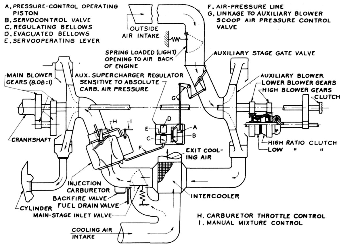 Fig. 7. Two-Stage Engine Installation Diagram |
An installation diagram for an engine with a two-stage supercharger is shown in Figure 7. Engine air enters the first-stage supercharger from the outside, passes the first-stage throttle valve, and enters the first-stage impeller. After compression, air leaves the first-stage supercharger from one or two outlets although only one outlet is shown for the sake of clarity. The air then passes through the intercoolers and, if two are used, is merged ahead of the carburetor. When the first-stage supercharger is not running, air is taken through the interstage inlet valve as shown on the diagram. This valve is lightly spring-loaded and closes just as soon as the pressure inside the duct is greater than the atmospheric pressure. Backfire valves should be installed in this duct to prevent it from bursting in case of an engine backfire. If there is danger of carburetor icing, a preheater must be provided for the air taken through the interstage valves. No preheater is necessary ahead of the first stage because the supercharger itself will do all the heating necessary. It may be desirable, however, to provide in the duct leading to the first stage a spring loaded valve that will open to the engine compartment in case the duct becomes clogged with snow.
Intercooler Types
An intercooler is a heat exchanger, and the name "intercooler" was chosen because this heat exchanger was interposed between two compression stages. The name now has come into widespread aeronautical use as meaning any heat exchanger used for cooling the engine air, regardless of its position in the induction system.
Like radiators, intercoolers may be constructed in a great many different ways, but so far most of them have been made either out of tubes or out of sheet metal. The tubular-type intercooler is usually constructed so that the engine air flows through the inside of the tubes and the cooling air over the outside, although intercoolers have been made in which the reverse is true. The ends of the tubes may either be expanded to a hexagonal shape so
.that they nest together like a honeycomb, or the tubes may be fastened in a header as in-boiler construction. Figure 8 shows an early tubular-type intercooler installation in which the engine air flows over the outside of the tubes, from the bottom to the top of the core.
The heat transfer from the engine air to the cooling air is through the walls of the tubes and, since the walls are thin (usually less than 0.010"), the coefficient of heat transfer of the tube material has little effect upon the intercooler efficiency.
Intercoolers made of sheet metal may consist of alternate layers of flat and corrugated sheets. Each section of corrugated sheet may be called a tube, and the intercooler is made up of alternate cooling-air and engine-air tubes. Part of the heat flow from the engine air to the cooling air is parallel to the surface of the corrugated sheet, then through the bond between the corrugated and the flat sheets, and into the cooling air. The surface of the corrugated sheet is called the indirect cooling surface, while the surface of the flat sheet is called the direct cooling surface. The ratio of indirect to direct cooling surface may be 5:1 or 6:1. The coefficient of heat transfer of the corrugated material may have an unpredictable effect on the efficiency of this intercooler. A sheet-metal intercooler installation of early design made by the Harrison Radiator Division is shown in Figure 9.
 |
 |
| Fig. 8. Tubular Type Intercooler Installation | Fig. 9. Sheet Metal Type Intercooler Installation |
Intercoolers are usually of the cross-flow type, which means that the cooling air and the engine air do not flow parallel to each other. The cross-flow arrangement is not the ideal way to build a heat exchanger because, since the heat transfer depends upon the temperature difference between the cooling air and the engine air, the heat flow is unequal throughout the intercooler. The greatest temperature difference occurs at the section where both the cooling and the engine air merge as they enter the intercooler. In a similar manner the least heat flow occurs at the section where both the engine air and the cooling air leave the intercooler. More heat transfer per cubic inch of intercooler would occur if the engine air and the cooling air flowed opposite and parallel to each other, but in this type of construction it is difficult to separate the cooling air and the engine air as they enter and leave the intercooler.
Up until the present time construction of intercoolers has tended to follow the method used in automobile radiator practice. The material used is either copper or brass dipped in solder. Copper and solder construction is very heavy, and it has only been the lack of demand, or possibly the lack of initiative on the part of the intercooler manufacturers, that has delayed the development and the adaptation of lighter construction. The weight of an intercooler made of aluminum, for example, should be less than half the weight of one made of copper. The difficulties in aluminum construction have been due to a lack of a satisfactory solder and to the difficulty of welding very thin surfaces. It may also be possible to develop intercoolers made of steel as well as of aluminum.
If the intercooler manufacturer is given this data, he should be able to specify the dimensions and the weight of the intercoolers that will do the job. Experience has shown, however, that only an unusual installation will permit the intercoolers to perform as expected. It therefore pays to be somewhat conservative and estimate a somewhat larger size rather than to try to keep the intercoolers just as small as possible. For example, to be very safe it is best to choose a cooling-air temperature at least 45°F above standard to take care of hot weather flying, temperature rise due to adiabatic compression in the cooling-air duct, and perhaps some radiation or spillage of cooling air from the engine. The intercooler should not be so large as to entail considerable extra weight to take care of some infrequent condition .when this condition cannot cause damage to the engine.
It is current practice to choose an intercooler that will permit an engine to deliver its rated power with atmospheric temperatures about 30° F higher than standard and with a pressure drop equivalent to 8 inches of water at sea level. Under certain conditions intercoolers chosen on this basis would be too small, because at high altitudes the climbing speeds would have to be very high to permit the attainment of this pressure drop after the duct losses are considered. The engine manufacturer must be careful that the operating conditions which he specifies are the hardest ones for the intercooler to meet. The severest conditions do not necessarily occur at the critical altitude and the highest impeller speed but may occur at the altitude where any impeller speed gear ratio is first engaged because the atmospheric temperature is higher at this point and the temperature rise through the supercharger is approximately the same as at the critical altitude. It must always be remembered that the intercooler discharge temperature should not be allowed to run so high that the engine will detonate.
The choice of an intercooler is always a compromise between engine performance and weight, and the final answer is obtained from experience gained in actual flight tests.
Intercooler Position
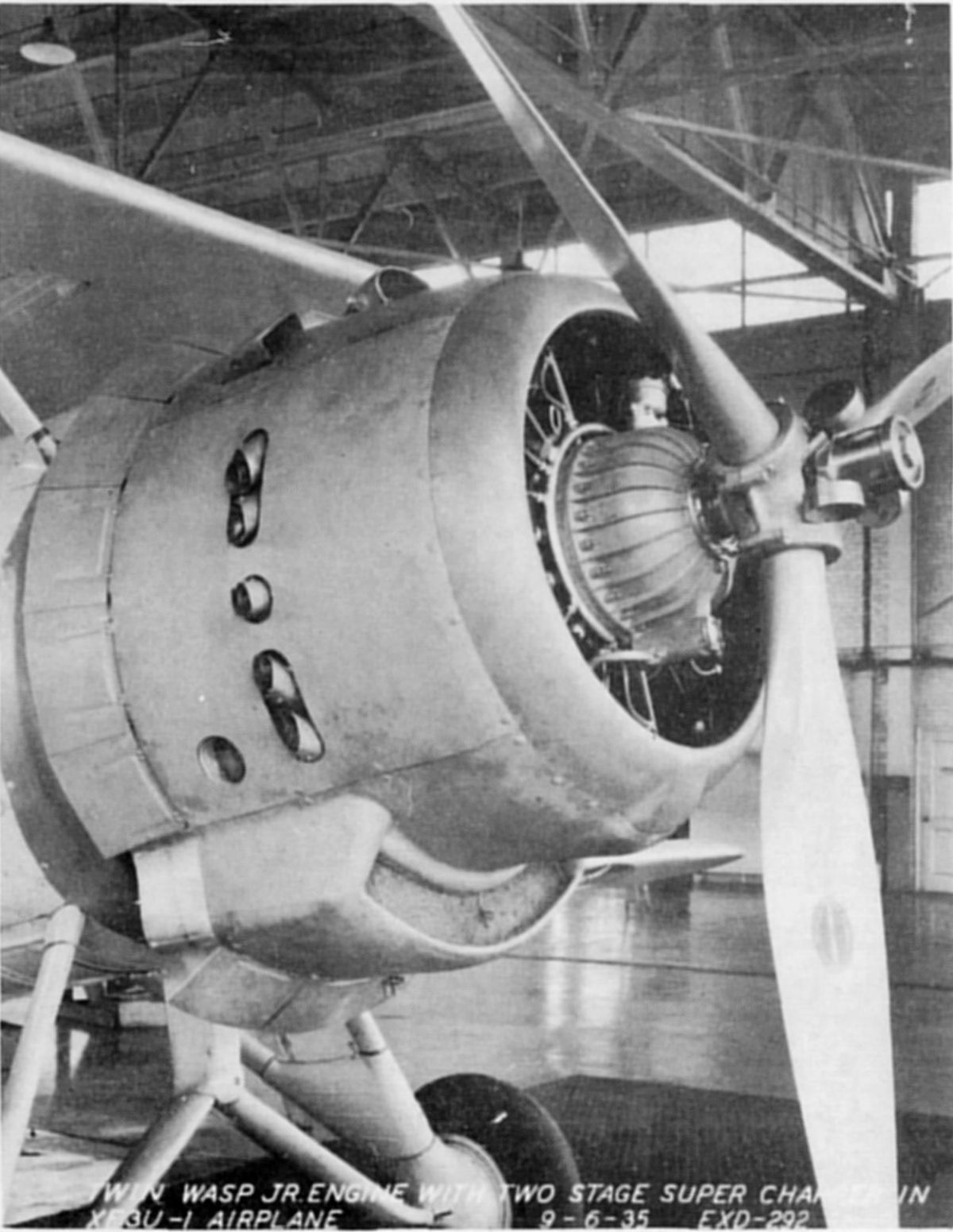
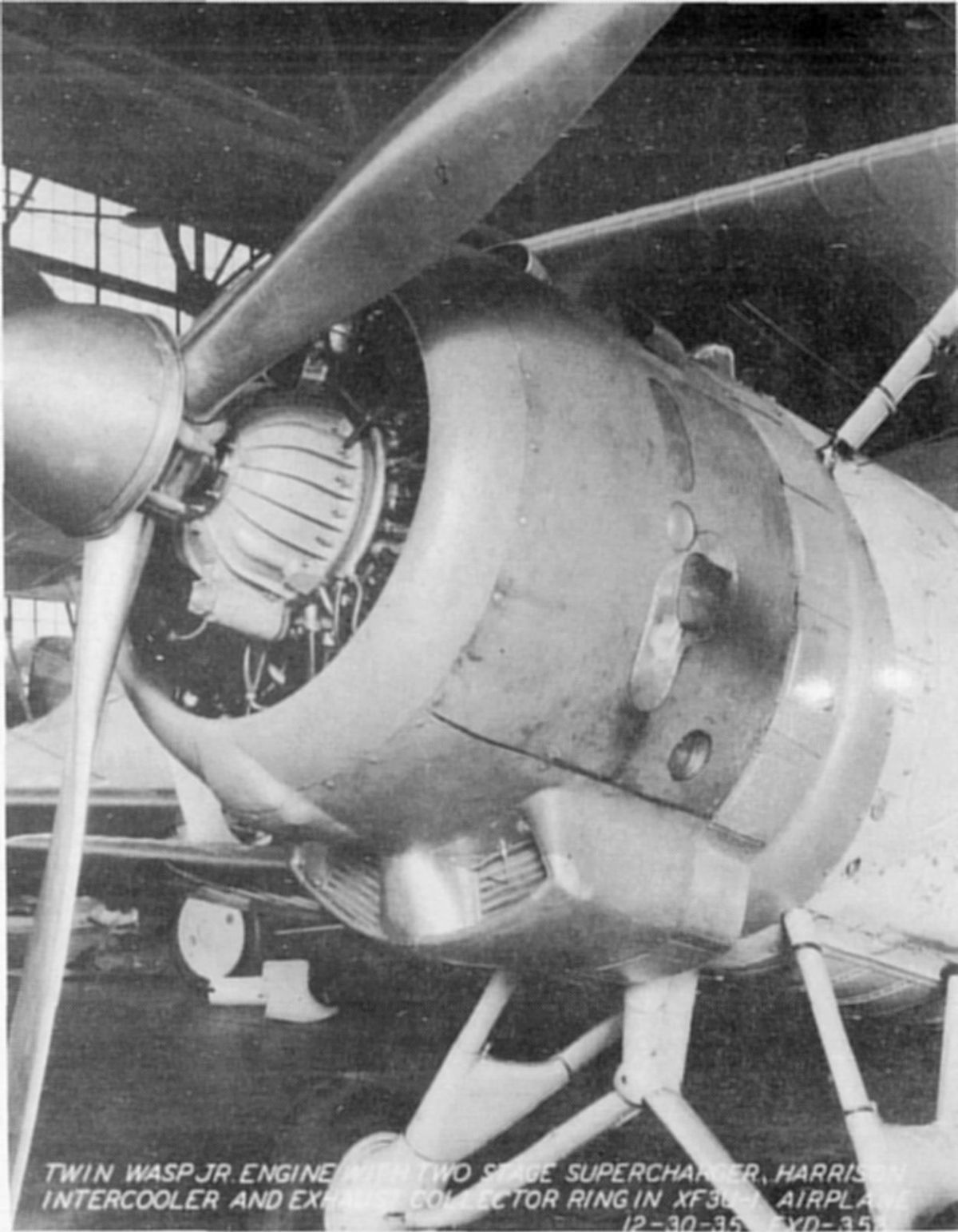
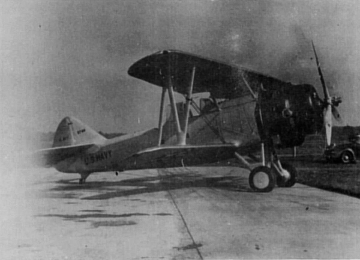
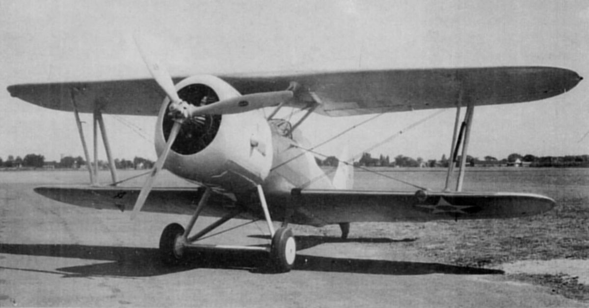
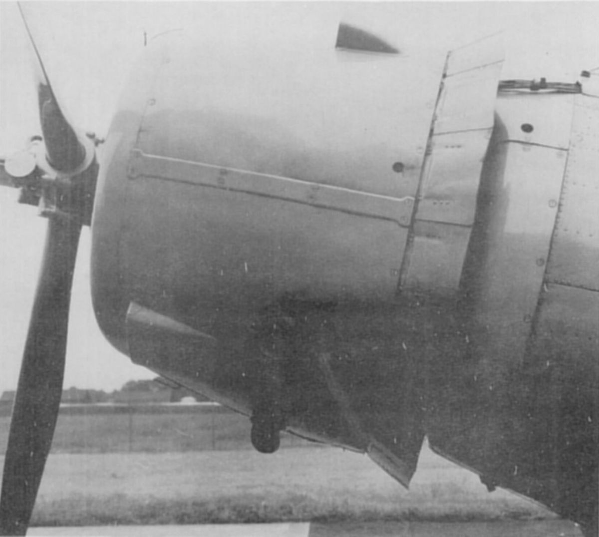
The position selected for the intercoolers depends entirely on the airplane. One of the early Navy two-stage supercharger installations is shown in Figure 10. In this case, the engine-air ducts connect to a double intercooler hung beneath the engine. There are really two intercoolers in this installation, although their outlet ends are connected to save space. Since these intercoolers hung entirely outside the airplane, they probably caused a considerable increase in drag.
If a downdraft carburetor is used, the intercoolers will normally be disposed above the center line and, if an updraft carburetor is used, the intercoolers will normally be disposed below the center line.
Some airplanes have wings thick enough to accommodate the intercoolers inside the wing If this is not the case, the intercoolers should be enclosed in the engine nacelle or the fuselage to reduce drag to a minimum. Figure 11 shows an airplane in which the intercoolers are enclosed on either side of the engine below its center line, and the cooling air for these intercoolers is obtained at the leading edge of the nose cowl. Figure 12 shows another installation on which the cooling air for the intercoolers is taken through short scoops.
 |
 |
 |
| Fig. 10. Navy Vought XF3U-1 with Two-Stage Engine |
Fig. 11. Navy Douglas XFD-1 with Two-Stage Engine |
Fig. 12. Navy Douglas XTB-1 with Two-Stage Engine |
Intercooler Ducts
The purpose of the engine-air ducts is to conduct compressed air to and from the intercoolers with minimum pressure loss and also to distribute the air evenly to the intercoolers so that they are used to their full advantage. It is generally good practice to keep the air velocity in the engine-air ducts below 150 fps, although this value may be exceeded in straight runs. If the velocity is kept low, losses due to changes in direction are not so serious. The losses in a duct may be caused by too sudden changes in direction, too rapid changes in area, and irregularities in the walls. It has been found from experience that it is riot difficult to keep the total losses between the first-stage outlet and the carburetor inlet to less than 11 inHgA.
It is desirable to put vanes in sharp bends to reduce velocity losses and to improve distribution, particularly when these bends are close to the intercooler. When the vanes are installed mainly to obtain good distribution over the intercooler face, they should be' spaced not more than 1 inch apart.
The ducts connecting the intercoolers with the engine must be heavy enough, to withstand vibration and backfiring. Flexible connections should be used at frequent intervals in the ducts, and it is essential that flexible connections be used in the engine-air ducts immediately before and after the intercoolers. These connections will prevent vibration of the ducts from being transmitted to the intercoolers. Molded neoprene boots strengthened with fabric have been found satisfactory for these connections. It is advisable, although expensive, to mold a bead on the edges of the boots to prevent internal pressures from pulling the ends out from under the hose clamps. Where extreme flexibility is desired, a bellows section may be molded in the connection.
The equivalent free-passage area of intercoolers may be between 15% and 55% of their frontal area.
The cooling-air duct entrance may therefore be quite small and still take all the cooling air possible. The entrance must be located in such a position that the maximum dynamic head is available both in level flight and in climb. Passages leading from the entrance to the intercooler must be as straight as possible with gradual expansion to convert dynamic head into pressure head with the least turbulence. It is good practice not to make the included angle of the duct walls greater than 10°. These ducts are usually part of the airplane structure and their position should be considered during the initial airplane design stages.
Intercooler Mounting
The sturdiest intercooler is usually a very flimsy affair, because it is made of thin material, and has to be very carefully supported. Any bracket soldered or fastened to part of the intercooler core is likely to crack the core. If the intercoolers are made with integral engine-air ducts it is usually preferable to make the supports on the ducts rather. than on the intercooler. Intercoolers are nowadays usually made with flanges that can be bolted to the engine-air ducts and, if these flanges are stiff enough, they may be used to support the intercooler. If the intercoolers are mounted directly on the engine they are likely to shake off because of engine vibration, so that it is usually desirable to mount the intercoolers on the airplane structure.
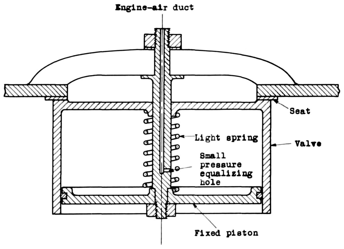 Fig. 13. Balanced Backfire Valve |
Backfire Valves
High pressure may be developed in the engine-air duct ahead of the carburetor because of backfire. With updraft carburetor installations, fuel may spill into the duct, giving an explosive mixture that may also cause high pressure and will cause a fire, if ignited. Ignition of this fuel may be prevented by installing a suitable flame trap in the system. Engine backfires may develop pressures as high as 150 psi, and it is impractical to design the duct heavy enough to withstand this pressure. Backfire valves should therefore be installed near the carburetor; these valves, when blown open, will discharge outside the engine cowling. A diagram of the backfire valve used in Pratt & Whitney engines is shown in Figure 13. It consists of a movable cup sliding over a fixed piston. The chamber inside the cup is connected by a small hole to the engine-air duct so that this chamber is always at the same pressure as that in the engine-air duct. Thus the valve may be kept in position with a light spring regardless of the difference between the internal and the external pressure. In case of a sudden backfire the rapid increase in pressure cannot be transmitted through the small hole quickly enough to equalize the pressure inside the chamber, and therefore the cup is blown open and the pressure inside the duct is released.
Two-Stage Engine Performance
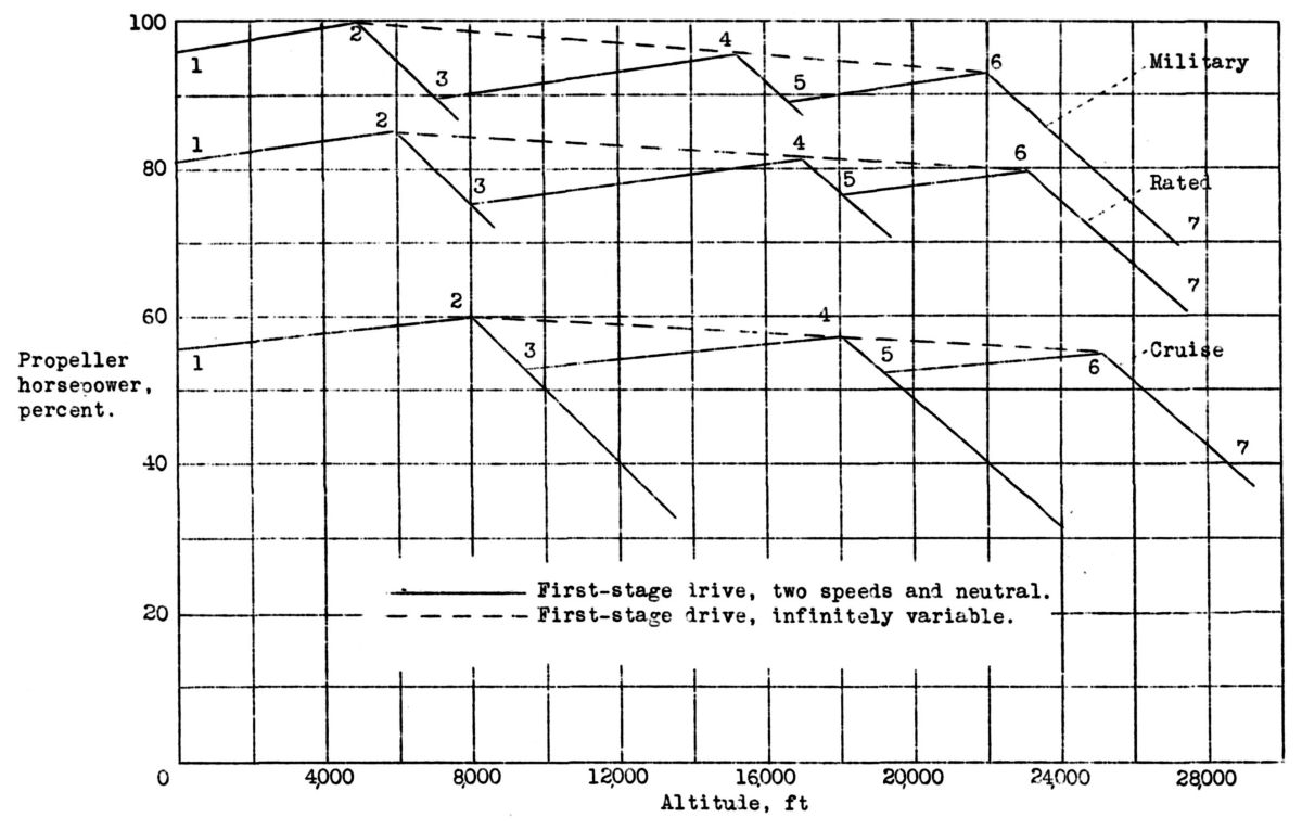 Fig. 14. Typical Two-Stage Engine Performance |
The performance of a hypothetical engine equipped with a two-stage supercharger is shown in Figure 14. The supercharger chosen for illustration is one with separated stages where the first-stage impeller has two speeds and a neutral position and the second-stage impeller operates at a fixed speed. The same general form of curve would be obtained from a cascade type of supercharger operating with a three-speed drive. The supercharger has automatic control maintaining a constant preselected manifold pressure below the critical altitude at each condition. Three sets of curves are shown: The upper one is, for a maximum power rating sometimes called military power; the middle one is for rated power; and the lower curve is for cruising power. The engine operates with its second stage only from points 1 to 3. From points 3 to 5 the first stage is operating at low speed, and from points 5 to 7 the first stage is operating at high speed. Point 2 is the critical altitude with only the second-stage supercharger, point 4 is the critical altitude for the first stage in low speed, and point 6 is the critical altitude for the first stage in high speed. Between points 1 and 2 the engine is taking its air from the interstage suction valves and. the power will increase because of the decrease in both carburetor-air temperature and exhaust back pressure. At altitudes above point 3, the air from the first stage is intercooled but between points 3 and 6, a change in atmospheric temperature will give about the same change in carburetor-air temperature. Thus, the power will also increase between points 3 and. 4 and points 5 and 6 owing to the decrease in carburetor-air temperature and exhaust back pressure.
The dotted line passing through points 2, 4, and 6 shows the performance when the engine is equipped with a variable-speed drive for the first stage. Thus, the triangles below the dotted lines represent the saving in power that would be possible. The dotted line slope represents the net loss in engine power due to the power required to drive the supercharger.
The critical altitude of an engine with a two-stage supercharger, as of one with a single-stage supercharger, depends entirely upon the rating selected. It is obvious that the lower the power or the manifold pressure chosen for a given supercharger speed, the higher the critical altitude is going to be. It is also obvious, that the higher the supercharger speed, as determined by the engine speed, the higher the critical altitude, will be. The supercharger takes a lot of power to drive it; and the higher the supercharger speed, the less the brake horsepower left for driving the propeller. The high-speed supercharger also requires more intercooling, which results in increased drag, and thus the problem of selecting a rating becomes very complex. The engine rating can then be chosen only after careful consideration off all factors. The engine sea-level rating being known, the altitude rating may be a matter of selecting the altitude at which the maximum airplane performance is required, and the engine power at altitude will be the sea-level power minus approximately the additional power required for supercharging.
After the altitude performance has been selected, some means must be provided for maintaining this altitude performance. This performance is usually maintained by means of an automatic pressure control, as previously described, This control can operate to maintain constant pressure in some part of the induction system after the first-stage supercharger. If the engine speed remains constant, this operation will result in a more or less constant manifold pressure and constant indicated horsepower. Actually, since the device is a pressure control and not a density control, changes in atmospheric temperature will cause changes in engine horsepower. This condition is not serious because, although a slightly lower temperature will cause some increase ii engine power, this temperature may be beneficial -in that the tendency for engine detonation is reduced. Thus, the two effects will tend to counteract each other for the temperature range actually experienced at any fixed altitude.
The actual performance of a two-stage supercharger can be determined on a dynamometer stand equipped with means of producing altitude conditions at the inlet and the exhaust. The performance can be determined also in flight by means of a torque meter for measuring power. The performance in flight is usually found to differ considerably from the performance on the dynamometer stand, but the cause of these differences can sometimes be determined. In flight there may be enough ram produced in the supercharger entrance to give 2,000 or 3,000 feet more critical altitude. The difference in the exhaust back pressure produced by a collector will also tend to change the performance slightly. The difference between cooling the cylinders and the induction system on the stand and in flight will also cause some performance difference. It is very difficult to measure true pressures and temperatures in air ducts, particularly those in which the air is more or less turbulent. Owing to the high over-all compression ratio of the two-stage supercharger, very slight changes in the inlet system can produce quite marked changes in manifold density and resulting performance. Thus, a comparison between dynamometer and flight operation can never be extremely accurate.
Flight tests are usually made to determine airplane performance and flight characteristics. Engine performance is usually obtained only to insure that the airplane performance is truly representative. Too frequently there is not enough time to make a thorough investigation of engine performance, and the .lack of information has been a handicap to both engine and airplane manufacturers. If two experimental airplanes could be built at once, it would be a great advantage to use one for engine-performance tests and the other for airplane-performance tests.
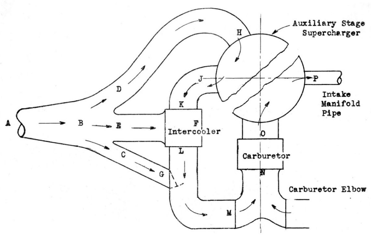 Fig. 15. Test Measurement Locations: A = Free Air Stream; B = Air Intake Duct; C = Interstage Suction Valve Entrance; D = Auxiliary Supercharger Stage Air Intake; E = Intercooler Entrance (Cooling Air); F = Intercooler Exit (Cooling Air); G = Interstage Suction Valve; H = Auxiliary Stage Supercharger Entrance; J = Auxiliary Stage Supercharger Exit; Intercooler Entrance (Engine Air); Intercooler Exit (Engine Air); M = Carburetor Elbow Entrance; N = Carburetor Entrance; O = Main Stage Supercharger Entrance; P = Fuel Air Mixture (Intake Manifold) |
The, operation of an engine with two-stage supercharger in flight is essentially no different from that of an engine with a single-stage supercharger. It is necessary, however, to obtain a great deal more information during initial flight tests of a new model because the engine performance is influenced to a great extent by the installation itself. It is necessary to know whether or not satisfactory intercooling is obtained, what the duct losses are, and whether the automatic controls are functioning properly. In order to obtain this information, pressures and temperatures throughout the induction system must be obtained; the diagram in Figure 15 gives the location for these test measurements. Thermocouples connected to a selective switch and a potentiometer may be used for obtaining temperatures. The static pressures throughout the system may be obtained by fastening fittings containing a No. 50 drill-size hole flush with the inside of the ducts to a bank of valves in the cockpit. Total pressures may also be obtained from carefully located impact tubes if the extra work required is warranted. A sensitive manifold pressure gage may be used for reading the pressures. The pressures that are read may not be very accurate because of the turbulence existing in the ducts, but they will be satisfactory for all practical purposes and will indicate whether or not the supercharger and controls are functioning properly. In order to obtain accurate measurements, total pressures would have to be taken in places where all turbulence had died out, which can only be done by using straight sections ahead of the measurement points.
First flights for engine performance should be made to familiarize the pilot with the operation of the engine and to determine whether the installation is functioning properly. The next step is to determine the critical altitudes at the various engine ratings and this determination can be made by making short, level-flight runs at several altitudes at each supercharger speed. After three or four points are obtained below and above the approximate critical altitude for each speed, the exact critical altitude can be found by projecting the corrected curves through these points. Inasmuch as the critical altitudes are entirely determined by the setting of the automatic controls, the controls can be reset if they differ too much from the desired values. If atmospheric conditions differ much from standard (which is the usual case), corrections to both the supercharger and the engine performance must be made before the true critical altitudes can be determined.
Further flight testing in both climb and level flight is required to obtain a complete picture of the engine performance and to determine whether or not the engine cooling and intercooling are satisfactory. It is advantageous to make check runs on days with different temperature conditions to insure that the installation will cool in hot weather.
All of this flight testing is expensive and uses up valuable time, frequently delaying the delivery of the airplane. Experience has shown, however, that it must be done eventually; so, where the saving of time is of primary importance, more than one experimental airplane should always be built.
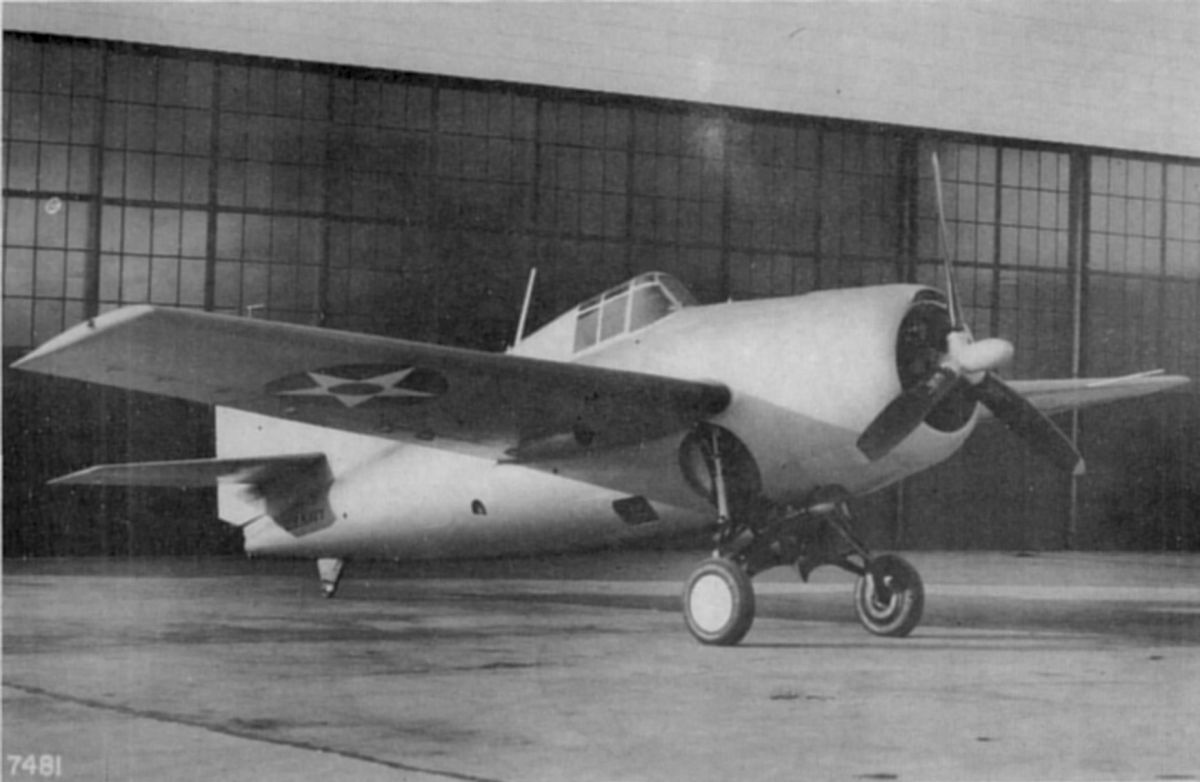
During the last few years, much progress has been made in two-stage supercharging both for the mechanical and turbine drive types. The U. S. Navy, realizing the possibility of two-stage superchargers several years ago, has sponsored a great amount of development and flight testing since that time. Photographs of two of the most recent Navy airplanes with two-stage superchargers are shorn in Figures 16 and 17. Comparing these photographs with those shown in Figures 10, 11, and 12 illustrates the progress made in two-stage engine installations.
 |
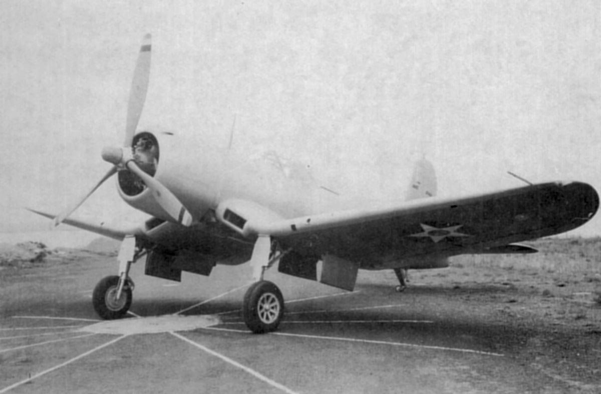 |
| Fig. 16. Navy Grumman XF4F-3 | Fig. 17. Navy Vought XF4U-1 |
Conclusions and Recommendations
1. It will be seen from the foregoing discussion that the two-stage mechanically driven supercharger itself is a comparatively simple device; and it is only the addition of intercoolers and controls that makes its installation any more difficult or complicated than that of a single-stage supercharger. These parts are usually added more fully to utilize the available performance of the two-stage supercharger. The installation of intercoolers and ducts is not difficult, provided that it is based upon flight-test experience.
2. The relative advantages of exhaust turbine-driven and mechanically driver, superchargers should be determined in several types of modern high-speed airplanes. Two of each type of air,-plane should be obtained, one equipped with an exhaust-driven and the other with a mechanically driven supercharger. The engines, the supercharger compressors themselves and their installation, including intercoolers, should be as nearly alike as possible. The available energy from the turbine and engine exhaust should be used to practical advantage in each case.
3. Supercharging requirements are increasing at such a rapid rate that the single-stage compressor will soon fail to meet the demand for many types of flying. Although supercharger research should increase the performance of the single-stage compressor, radical changes with perhaps an entirely different form off supercharger would be required to eliminate the necessity for two-stage centrifugal supercharging. Two-stage supercharging in its present form must therefore be given serious consideration for most types of airplane if the present trend of engine performance is continued.
Send mail to
![]() with questions or comments about this web site.
with questions or comments about this web site.
![]()