
WWII Gunnery Target Engine Technical Analysis
Part 6. Performance and Efficiency Comparison between O-45-1 and O-45-35 Engines
by Tom Fey
Published 19 Jun 2017; Revised 28 Dec 2017
Contents
Part 1. Background and General Configuration
Part 2. The Righter 2-GS-17 (O-15-1) in Detail
Part 3. The Righter O-15-3 Engine
Part 4. Performance and Efficiency Comparison between O-15-1 and O-15-3 Engines
Part 5. The O-45-1 and Kiekhaefer O-45-35
Part 6. Performance and Efficiency Comparison between O-45-1 and O-45-35 Engines
Part 7. Conclusion
O-45-1 and O-45-35 Performance and Efficiency
The increased horsepower of the O-45-35 is due primarily to an increase in compression ratio, specifically, a 18% boost from 5.24 to 1 to 6.2 to 1. A modest squish band and filling of the end-gap at the top of the cylinder liner is what reduced the clearance volume to 49.3 cc in the O-45-35 compared to the 59 cc of the O-45-1 .While the other drone engines could use fuel with octane ratings as low as 72, the O-45-35 demanded 91 octane gasoline. Additionally, the O-45-35 was spun at 4,250 rpm to achieve the 35 horsepower, compared to the 3,650 (20 hp) to 4,000 rpm (22 hp) of the O-45-1. But beyond the compression ratio, what other modifications enabled the 59% increase in horsepower, 50% increase in torque, and 6% greater rpm from the O-45-35 compared to the O-45-1 of the same displacement?
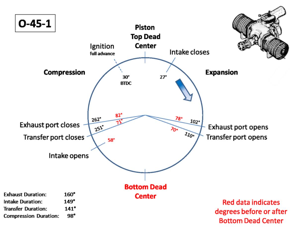
It is clear that a significant effort was expended to improve airflow through the engine. The carburetor bore (67% greater area), carb intake trunk (46% larger area), and especially the transfer manifold are larger than the O-45-1, as are the diameter of the rotary valve (5" versus 4.75") and the size of the rotary valve cut-out (56% larger in area). The piston has three rings instead of the two-ring O-45-1, and the crankcase has additional internal sculpting perhaps for strength but also better direct and smooth airflow. The intake phase starts 23° earlier and lasts 31° longer than the O-45-1. The height differential between the transfer and exhaust ports is 76% wider (0.235" versus 0.122") in the O-45-35, opening the exhaust ports sooner than the O-45-1 and giving more time to exhaust the gasses and reduce cylinder pressure before the transfer ports open to scavenge the cylinder. Interestingly, the transfer and exhaust port areas in the cylinder wall, transfer duration, and exhaust duration differ little between the O-45-1 and O-45-35, so these parameters appear to not have been a limiting factor of engine performance in the O-45-1/O-45-35 engine design.
It is also obvious the designers of the O-45-35 had to better control the two-throw crankshaft tail as revealed by a doubling of roller bearings and then adding a ball bearing to the engine rear case. A lightened points contact arm was used, perhaps to reduce inertia effects (float) at the higher design rpm for this engine. The O-45-35 also required a 6 to 1 fuel-to-oil ratio while some of the smaller engines had gone to 8 to 1 or 10 to 1 ratios, thereby insuring adequate lubrication and perhaps a modicum of heat rejection through the discharged oil.
But what is most striking is the significant increase in heat rejection on the O-45-35. The beautifully die-cast fins on the O-45-35 cylinder total 4.77 ft² of surface area, but this only 12% more surface area than the 4.17 ft² of the O-45-1. This works out to be 0.14 ft² of fin area per horsepower for the O-45-35 and 0.19 ft² of area for the O-45-1. In comparison, the eight horsepower O-15-3 engine has 0.32 sq. ft. and the 6.5 horsepower O-15-1 engine 0.43 sq. ft. of cylinder fin area to dissipate one horsepower. As a rough comparator, the wartime Wright R-3350 radial of 2,200 horsepower (a highly supercharged four-stroke engine with pressure cowling, baffled cylinders, oil coolers, etc.) has 0.22 ft² of cylinder fin area per horsepower. Thus the O-45-35 is trying to reject 47% more horsepower-heat per unit fin area than the R-3350!
In addition, the O-45-35 powered OQ-17/TDR-1 was the first Radioplane design to incorporate full cowling of the engine and cylinders. The Smithsonian/NASM has zero documents on the OQ-17 or the O-45-35 engine, and I am aware of only the one photograph of the Q-17 as shown in this document. In the absence of documents and a surviving airframe, I cannot definitively state whether the cylinders were baffled. On one hand this was a "low cost", disposable, unmanned target drone, so why bother, while on the other hand, the importance of pressure baffling for air-cooled engines was well understood long before 1945. The plethora of tapped holes in the O-45-35 cylinder alone (the O-45-1 has no tapped holes except for the spark plug) tends to support the use of baffling on this engine.
The OQ-17 had a 5 gallon fuel tank that provided flight duration of 1 hour for a specific fuel consumption of 0.88, which is slightly better than the 0.9 of the O-45-1. At 143 pounds gross weight at takeoff, the OQ-17 was at the mechanical limit for the bungee-powered A-2 catapults (700 lb of tension) used for the previous target drone aircraft.
It is my opinion that the anecdotal unreliability of the Kiekhaefer O-45-35 was likely due to the increased heat rejection demands of the high-horsepower engine exacerbated by the novelty of the cowled airframe. The uncowled O-45-1 on the OQ-14 did its work bathed in turbulent open air. While there is perhaps some cooling benefit afforded by the 190 mph airspeed of the O-45-35 powered OQ-17 compared the 140 mph of the O-45-1 powered OQ-14, it is likely minor compared to the large discrepancy in thermodynamic load placed on the O-45-35 that has essentially the same metal mass and surface area as the O-45-1.
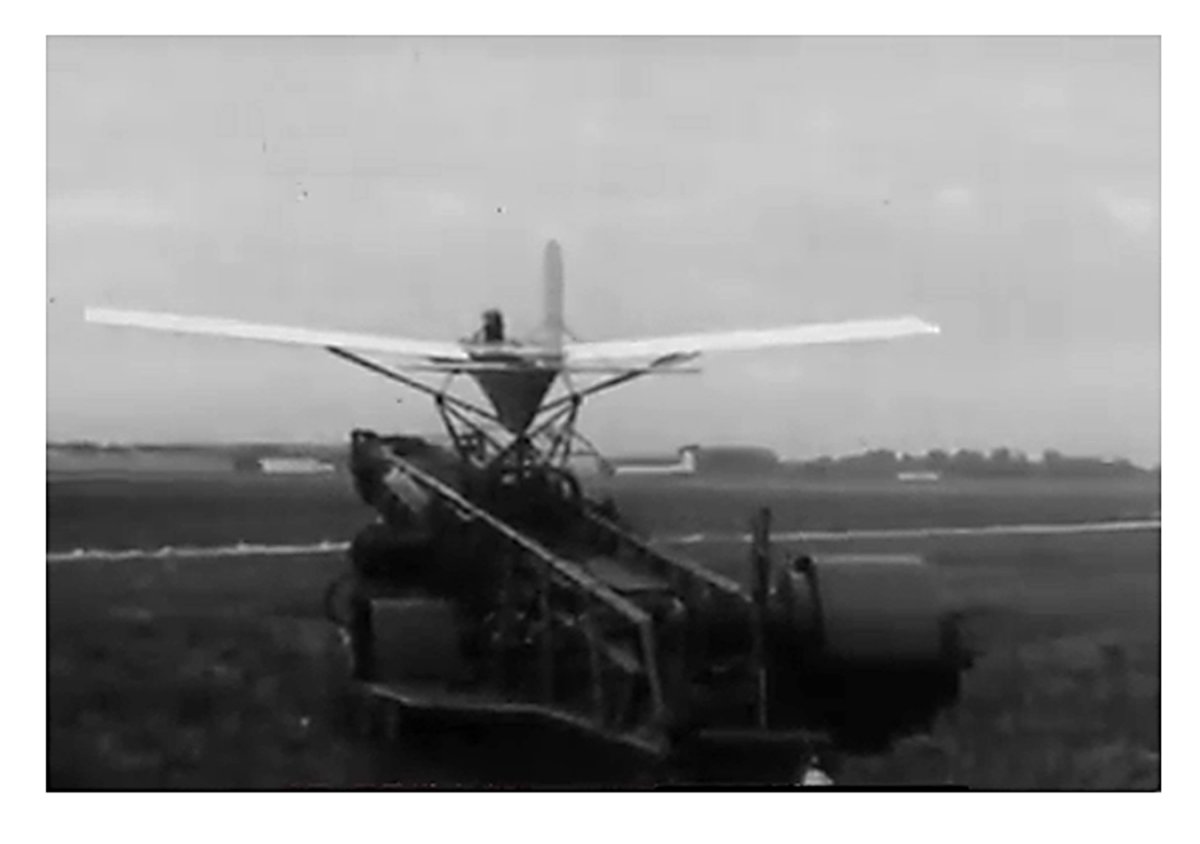
There is both cinematic (Search for video of 1946 Cleveland air Races) and photographic evidence that some O-45-35 engines made their way into the tube-and-fabric OQ-14/TDD-3 airframes. The crankcase mounting lug geometry is identical between the O-45-1 and the O-45-35, and with similar engine weights, the change would be very easy to execute. The uniform cylinder fin orientation and tall, forward-facing carb (which will not fit onto an unmodified O-45-1) are characteristic of the O-45-35 engine.
|
|
|
|
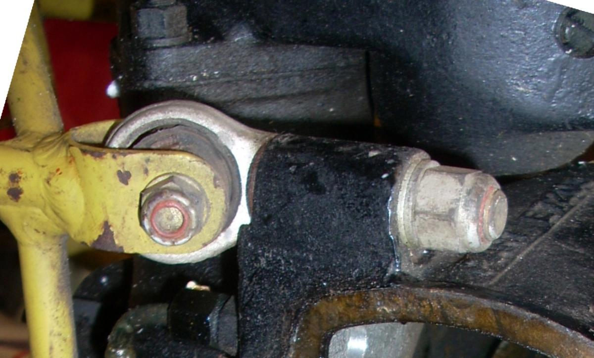
| OQ-14/TDD-3 Airframe with Kiekhaefer O-45-35 Engine at Rest | OQ-14/TDD-3 Airframe with Kiekhaefer O-45-35 Engine in Flight | Screenshot of the OQ-14/TDD-3 airframe with Kiekhaefer O-45-35 engine on the catapult taken from a film of 1946 National Air Races, Cleveland, Ohio. | All O-15 series and O-45- series engines were mounted using rubber-bushed angled eyebolts secured to crankcase lugs. A through-bolt secured the eyebolt to the welded clevis on the air frame. An 0-45-35 engine mount is shown here. Note delamination of the 70 year old rubber bushing at the 10 o'clock position. |
O-45 Engine Comparison
 |
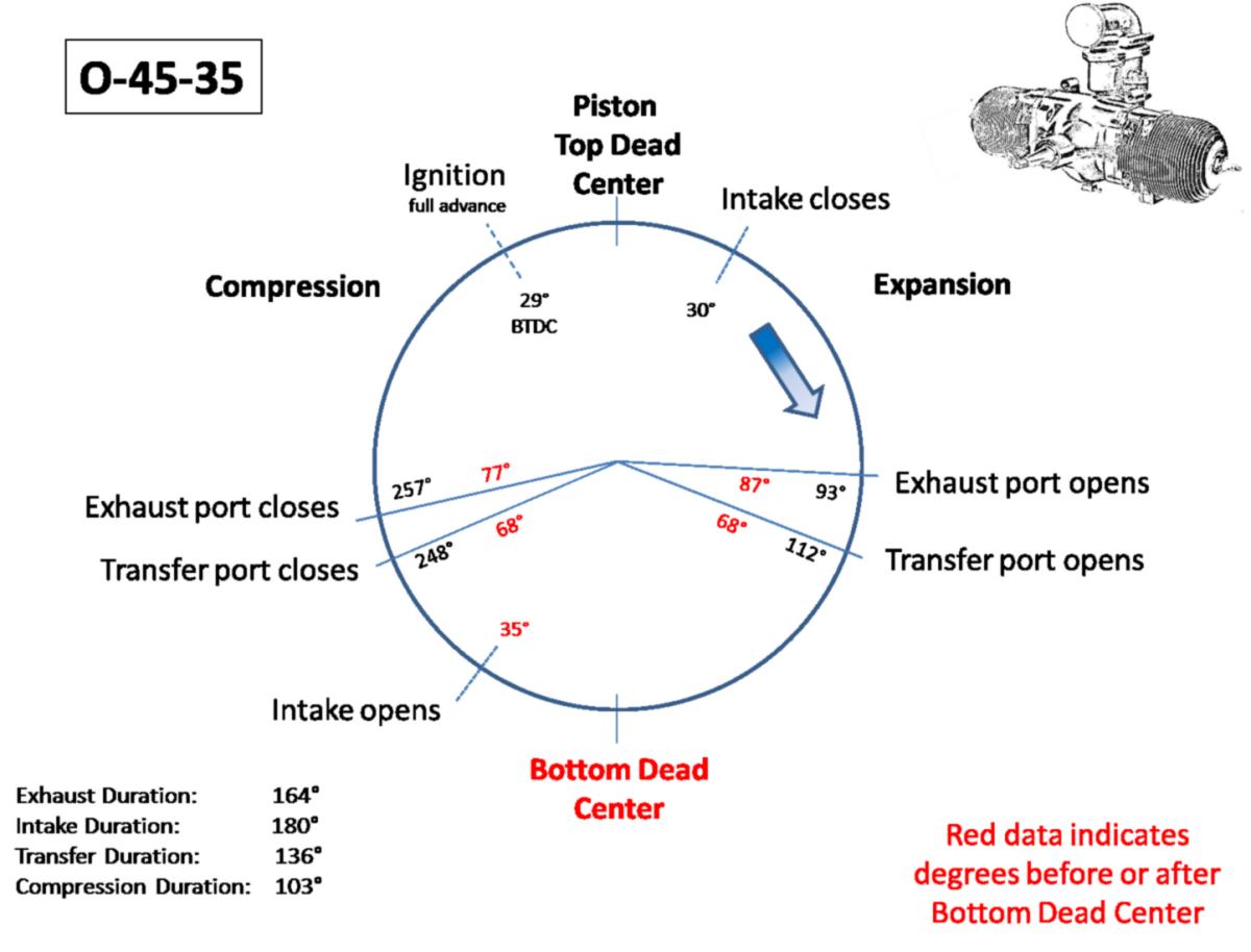 |
| O-45-1 Cycle Timing | O-45-35 Cycle Timing |
| Engine and Cylinder | Engine Swept Displacement (in³ (cc)) |
Bore (inches) |
Stroke (inches) |
Dynamic Stroke (inches) |
Company Nominal Comp Ratio |
Static Comp Ratio |
Dynamic Comp Ratio |
Clearance Volume (in³ (cc)) |
Static Volume (in³ (cc)) |
Dynamic Volume (in³ (cc)) |
Engine Dynamic Volume (in³ (cc)) |
|---|---|---|---|---|---|---|---|---|---|---|---|
| Kiekhaefer 0-45-1 | 45.6 (747 ) | 3.25 | 2.75 | 1.88 | 7 to 1 | 7.3 to 1 | 5.3 to 1 | 3.6 (59) | 26.4 (433) | 19.2 (314) | 38.4 (629) |
| Righter 0-45-1 | 45.6 (747 ) | 3.25 | 2.75 | 1.88 | 7 to 1 | 7.3 to 1 | 5.3 to 1 | 3.6 (59) | 26.4 (433) | 19.2 (314) | 38.4 (629) |
| 0-45-35 | 45.6 (747 ) | 3.25 | 2.75 | 1.86 | ? | 8.6 to 1 | 6.2 to 1 | 3.0 (49) | 25.8 (423) | 18.5 (302) | 36.9 (605) |
| Engine and Cylinder | Engine Cooling Fin Area (in²(ft²)) |
Cooling Fin Tip Gap (inches) |
Cooling Fin Base Gap (inches) |
Cooling Fin Tip Thickness (inches) |
Typical Barrel Fin Depth (inches) |
Outside Diameter (inches) |
Exhaust Stack External Area (in²) |
Weight (grams) |
|---|---|---|---|---|---|---|---|---|
| Kiekhaefer 0-45-1 | 614.4 (4.27) | 0.18 | 0.12 | Head=0.060 Body=0.065 | 0.64 | 5.0 | 2.8 | 2364 |
| Righter 0-45-1 | 618.2 (4.29) | 0.26 | 0.10 | Head=0.098 Body=0.078 |
0.55 | 5.0 | 12.64 | ? |
| 0-45-35 | 687.2 (4.77) | 0.145 | 0.088 | 0.045 | 0.88 | 5.45 | 1.696 | 2370 |
| Engine and Cylinder | Engine Crankshaft Length (inches)* |
Piston Ring Number and Thickness (inches) |
Rear Case Inlet Port Area (in²) |
Rear Case Inlet Port Arc (degrees) |
Intake Transfer Trunk Dimensions (inches) |
Cylinder Transfer Trunk Area (in²) |
Rotary Valve Cut Out Area (in²) |
Rotary Valve Cut Out (degrees) |
Rotary Valve Diameter (inches) |
Rotary Intake Open (° ABC) |
Rotary Intake Open (° BTC) |
Rotary Intake Close (° ATC) |
|---|---|---|---|---|---|---|---|---|---|---|---|---|
| Kiekhaefer 0-45-1 |
14.0 | 2 x 0.092 | 3.156 | 87 | (1.92 to 1.97) x 0.825 | 1.584 | 2.44 | 61 | 4.75 | 58 | 122 | 27 |
| Righter 0-45-1 |
14.0 | 2 x 0.092 | 3.156 | 87 | (1.92 to 1.97) x 0.825 | 1.584 | 2.44 | 61 | 4.75 | 58 | 122 | 27 |
| 0-45-35 | 13.5 (approximate) | 3 x 0.085 | 4.41 | 100 | (2.09 to 2.12) x 0.844 | 1.70 | 3.8 | 85 | 5 | 35 | 145 | 30 |
| Engine and Cylinder | Cylinder Transfer Port Area (in²) |
Exhaust Port Area (in²) |
Carb Deck Throat Diameter (inches) |
Intake Duration (degrees) |
Transfer and Exhaust Port Height Difference (inches)* |
Exhaust Port Open (° ATC) |
Transfer Port Open (° ATC) |
Transfer Port Close (°ATC) |
Exhaust Port Close (°ATC) |
Exhaust Port close (°ABC) |
Transfer Duration (degrees) |
Exhaust Duration (degrees) |
Exhaust Port Height (inches) |
Exhaust Port Arc Width (inches) |
Exhaust Port Area (in²) |
|
|---|---|---|---|---|---|---|---|---|---|---|---|---|---|---|---|---|
| Kiekhaefer 0-45-1 | 1.244 | 1.244 | 1.78 | 149 | 0.122 | 102 | 110 | 251 | 262 | 82 | 141 | 160 | 0.7 x 2 + 0.57 x 2 | 0.706 x 2 + 0.573 x 2 | 1.244 | |
| Righter 0-45-1 | 1.537 | 1.537 | 1.78 | 149 | 0.122 | 102 | 110 | 251 | 262 | 82 | 141 | 160 | 0.694 dia. X 4 | 4 x 0.699 | 1.537 | |
| 0-45-35 | 1.27 | 1.27 | 2.26 | 180 | 0.19 | 93 | 112 | 248 | 257 | 77 | 136 | 164 | 0.7 x 2 + 0.58 x 2 | 0.706 x 2 + 0.583 x 2 | 1.298 | |
| * From Direct Cylinder Measurement | ||||||||||||||||
| Engine and Cylinder | Engine Fin Area (in²(ft²)) |
Fin Area per HP (in²) |
Fin Area per HP (ft²) |
Connecting Rod Length (inches) |
Rod Length to Stroke Ratio | Rated HP @ RPM | Engine Torque (lb/ft) |
Engine HP/Dynamic Volume | Best Fuel Consumption (gph) |
Fuel Consumption (gal/hp/hr) |
Engine Specific Fuel Consumption (lb/hp/hr) |
Oil Ratio | Engine Dry Weight (lb) |
Engine Specific Weight (hp/lb) |
Engine Length (inches) |
Engine Width with Plugs (inches) |
|
|---|---|---|---|---|---|---|---|---|---|---|---|---|---|---|---|---|---|
| Kiekhaefer 0-45-1 | 614.4 (4.27) | 30.7 | 0.20 | 5.0 | 1.82 | 20 @ 3650 (22 @ 4000) | 28.8 (28.9) | 0.52 (0.57) | 3.20 | 0.15 | 0.90 | 6 to 1 | 34.5 | 0.64 | 16.375 | 24.0 | |
| Righter 0-45-1 | 618.2 (4.29) | 30.9 | 0.21 | 5.0 | 1.82 | 20 @ 3650 (22 @ 4000) | 28.8 (28.9) | 0.52 (0.57) | 3.20 | 0.15 | 0.90 | 6 to 1 | 34.5 | 0.64 | 16.375 | 24.0 | |
| 0-45-35 | 687.2 (4.77) | 9.8 | 0.14 | 5.0 | 1.82 | 35 @ 4250 | 43.3 | 0.95 | 5 | 0.14 | 0.88 | 6 to 1 | 35.0 | 1 | 14.625 | 23.312 | |
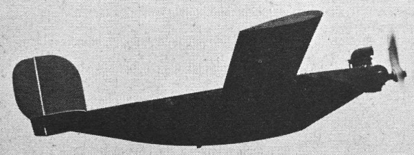
The Wee Bee
And lastly the Kiekhaefer O-45-35 did propel a man-carrying aircraft, namely the Wee Bee, which was designed, built, and flown by Ken S. Coward and Associates during 1948-1950. The team included Coward, Bill Chana, Karl Montijo, Bill Bouch, and James Wilder. The first iteration of the Wee Bee utilized a hybridized O-45-1 engine (fin count by photographic evidence indicates Menasco cylinders) built up from parts scavenged by Jim Wilder, but the reported 18 horsepower did not provide enough power for flight. The aircraft was then modified from a tail dragger to a nose gear configuration with a Kiekhaefer O-45-35 engine driving a 48" propeller. It appears that a spacer may have been introduced between the crankcase carburetor flange and the O-45-35 carburetor, which I presume held a throttle butterfly to offer some control of power during the various phases of flight. This sole aircraft was successfully flown at multiple venues and period film of the aircraft in flight can be found on the Internet courtesy of the San Diego Air and Space Museum. The original Wee Bee was destroyed in an arson fire in 1978, but a replica has been built and is on display at the San Diego Air and Space Museum.
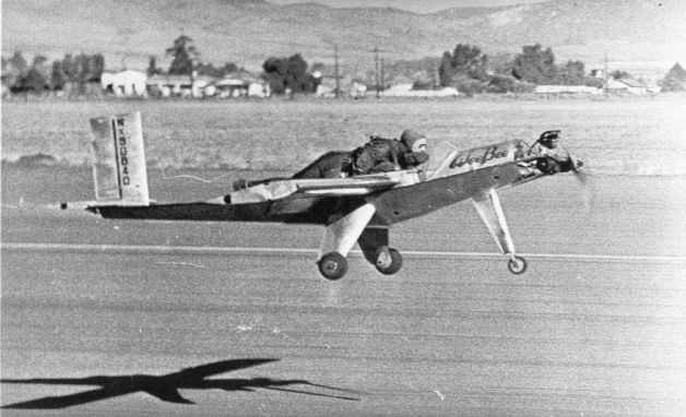 |
| Wee-Bee in Flight |
Send mail to
![]() with questions or comments about this web site.
with questions or comments about this web site.
![]()