Propeller Indexing
Published 9 Jan 2023
Introduction
People who work on certificated aircraft know that the Federal Aviation Administration is quite persnickety about propellers. Title 14 CFR Part 35 describes how a aircraft propellers are type certified. Title 14 CFR Part 23 § 23.907 establishes criteria that aircraft manufacturers must follow to assure that a type-certificated propeller works correctly on their specific engine / airplane combination, and AC 20-66B suggests when and how this is to be accomplished. Paragraph 7.a.(1)(a)(3) notes the "Propeller indexing relative to the crankshaft can affect propeller vibration characteristics and stress amplitudes." The aircraft manufacturer's FAA-approved maintenance manual usually gives specific propeller installation, maintenance, inspection and repair guidance, as does AC 43-13-1B Chapter 8 Section 4 § 8-71 ‑ 8-109, which is applicable to older aircraft without FAA-approved maintenance manuals. AC 43-13-1B also addresses propeller indexing in § 8-109e, "Cabin vibration can sometimes be improved by reindexing the propeller to the crankshaft. The propeller can be removed, rotated 180°, and re-installed."
During certification, propeller manufacturers typically build up a propeller with an internal load cell to mimic centrifugal force on the hub (which stiffens it), and then use electrodynamic shakers that shake the entire propeller it in various ways to identify all its vibration modes. The data collected gets fed back to the aero group where predictions are compared to the physical shake data. A composite blade design may sometimes have its laminate schedule changed to tweak its mode frequencies. Scimitar blades are a particular challenge as they have some weird bending modes due to their tip shape.
Often, a new propeller installation for an aircraft design whose overall airframe characteristics are similar to a previously-certified installation is a painless process. It is an engineering judgment call based on hard math that involves several engineering disciplines. If any question arises, a flight test often follows. Most installations are well-behaved, but sometimes the combination of airframe, wing, engine, and air inflow angles can excite the propeller in ways that don't respond to easy fixes. In typical turbine engine installations with four or more blades, one particularly insidious vibration is known as the 'reactionless mode' where propeller blade vibrations cancel each other out so there is no force transmission from the hub to the airframe to alert the pilot. Reactionless mode is usually excited in a quartering tailwind condition such as when the aircraft is taxiing downwind prior to takeoff. In these cases, placards to avoid continuous operation in certain rpm ranges may be required; rare worst cases may involve re-designs. For reciprocating installations, the undamped 4-cylinder Lycoming engines can occasionally be problematic.
Amateurs who build airplanes have more relaxed rules, but the FAA and their Designated Airworthiness Representatives are often very cagey about approving non-certificated propellers or propeller installations. The amateur builder is wise to follow the same propeller indexing, installation, maintenance, inspection and repair practices that certificated aircraft do. But how does one figure out how to index a homebuilt propeller? Usually the propeller manufacturer can help, and previously-proven aircraft/engine/propeller combinations aid the process. For example, Hartzell Manual 193 Information Manual for Experimental Aircraft Volume 1: Propeller Vibration Compatibility on Reciprocating Engines provides a wealth of information, but includes the following admonition:
I. Propeller Indexing
Propeller indexing, sometimes referred to as “clocking”, can significantly change the loads experienced in the propeller. This effect is mostly due to the relative angular position of the blades to the piston power pulses and to the resonant dynamics present in the engine crankshaft.
Care must be taken to ensure the correct indexing for the engine. See the section on engine specifics for more information about the appropriate indexing for propellers with optional indexing configurations.
Clearly, propeller manufacturers take this indexing business very seriously. Really big (and some small) propellers will only go on an engine one way. But many general aviation propellers can be installed in either three of four positions.
|
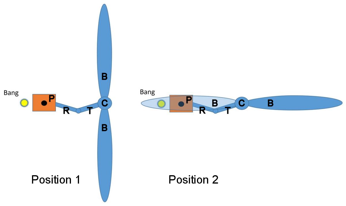
| Fig. 1. Representative Propeller Indexing Locations |
Torsional Considerations
Why does the propeller's position relative to the crankshaft matter? Figure 1 shows two possible propeller indexing choices. From a torsional perspective they appear to be equivalent. However, everything in the diagram is flexible to some extent: the blades (B), the crankshaft (C), the crankshaft throw (T), the connecting rod (R), and the piston (P). When a cylinder fires, the piston conveys the expanding gas force to the rod, throw, crankshaft and finally to the propeller. Along the way the flexible parts bend or twist or both and the rotating propeller, whose inertia resists the power impulse, is subjected to a complex torsional waveform that results from all the elastic pieces in the system. The propeller, excited by the crankshaft's torsional behavior, also bends and twists, further exciting the system with its own reaction. A propeller installed on a single-cylinder engine is close to torsionally equivalent in either position shown in Figure 1. But consider the system if the crankshaft throw is for a rear cylinder in a multi-cylinder engine, and compare that torsional system to one where the throw is for a front cylinder; clearly they are completely different. If propeller manufacturers tried to accommodate all possible potential vibration signatures for all possible engines they would never get a propeller certified. Instead, they choose a promising propeller index and make that work, which drastically reduces the work involved.
Shake and Shimmy
Another less obvious factor is influenced by propeller indexing. Anyone who has ever observed a running horizontally-opposed engine with a strobe light has seen an alarming sight. The crankcase writhes like a snake, the cylinders move like amber waves of grain, the whole engine moves around in its flexible vibration-isolating mount, and the propeller's bending and flapping make the faint-at-heart resolve to never fly behind one again. These behaviors affect propeller stresses and result from the engine's reaction to internal gas and inertia forces.
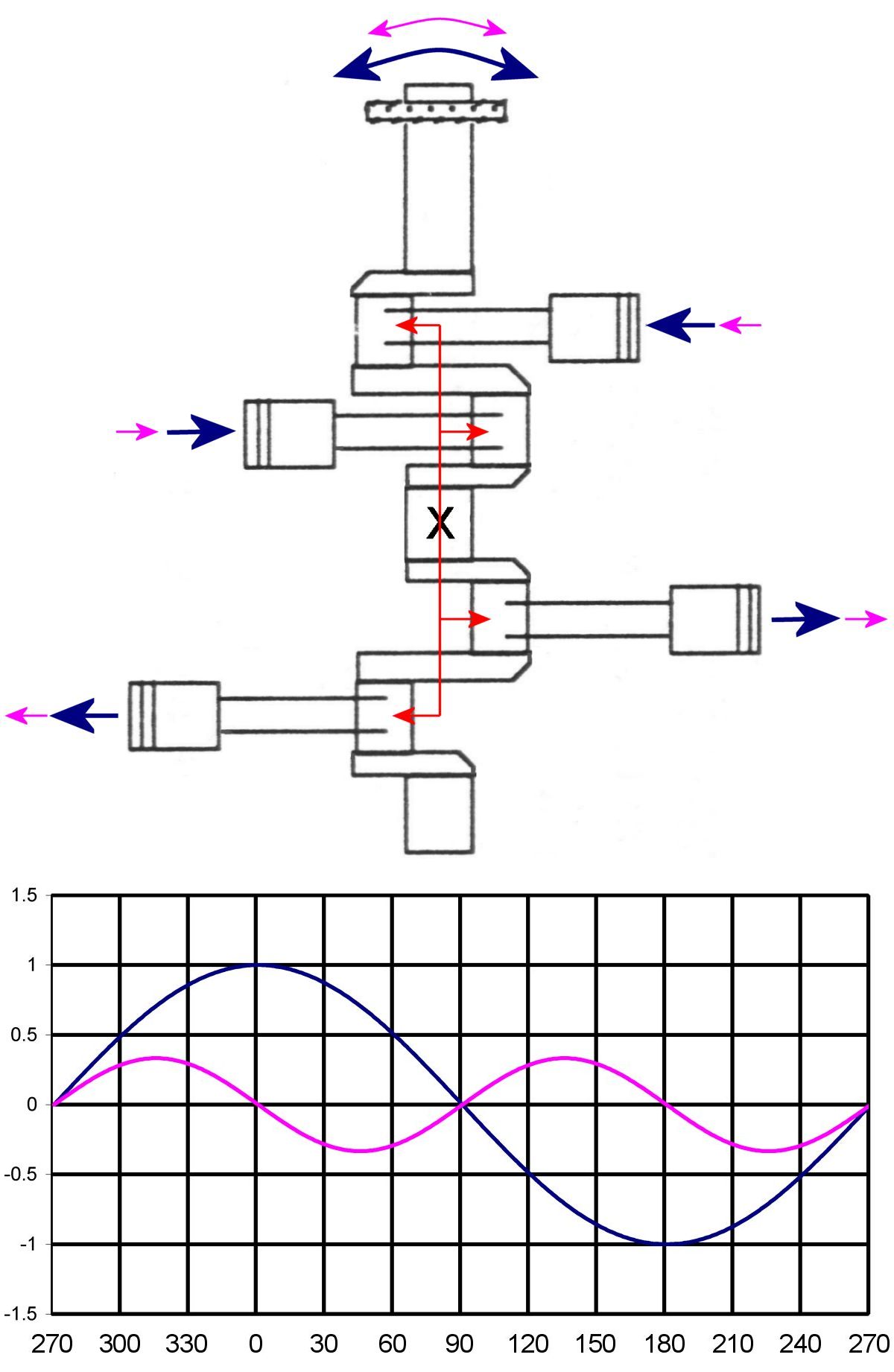 |
| Fig. 2. Inertial Forces |
Unresolved internal inertial forces are big contributors to the vibration described above. In Figure 2 these forces are examined for a four-cylinder horizontally-opposed engine. Two principle inertial systems are examined. The primary system (blue arrows and graph tracing) results from unresolved rotational imbalance that each crankshaft throw sees. Most horizontally-opposed engines don't have counterweights for each crank throw, as the opposite cylinder, moving in the opposite direction, mostly balances this rotational imbalance. However, the opposite crankshaft throws are offset from one another, so that the relatively large primary shaking forces (up to about 10,000 lb) do not directly counteract one another. Instead they create a rocking couple (shown in red) that tends to rotate the engine back and forth about its vertical axis (X). Since the primary unbalance is a rotational force it occurs once per crankshaft revolution.
A secondary force (magenta arrows and graph trace) results from unresolved reciprocating forces as the pistons and other reciprocating components stop and start at top center and bottom center. These secondary forces manifest twice per crankshaft revolution and are about a third of the primary magnitude. Again, the secondary forces do not directly counteract one another, but create a rocking couple (shown in red) that tends to rotate the engine back and forth about its vertical axis (X).
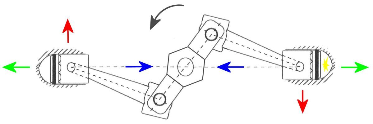 |
| Fig. 3. Engine Gas Forces |
Figure 3 depicts a horizontally-opposed engine's opposite cylinders. The view is from the anti-propeller end and shows the anti-clockwise crankshaft and propeller rotation typical of most general aviation aircraft engines. The right cylinder is on its power stroke. High pressure gas resulting from burning fuel and air exert a force on the engine (green arrow) that tends to move it to the right. An equal gas force on the piston (blue arrow) causes it to move toward the crankshaft. These gas forces are huge, typically several tens-of-thousands of pounds. Because the piston is connected to the crankshaft via a connecting rod, a side force (red arrow) is generated. This means that the green and blue forces are not equal (green is greater). Resolution of the green and blue gas forces causes the crankcase and crankshaft to flex. The red force causes the engine to momentarily rotate clockwise with every power stroke and the cylinder to flex up and down on the crankcase. The force combination causes the entire engine, which is attached to the airframe via flexible vibration-isolating mounts, to move in a way that slightly changes the rotating propeller's plane of rotation, a process that is repeated for every cylinder during every 720° engine cycle.
Other Considerations
The propeller excitation forces described above operate primarily in the horizontal plane causing the engine to rotate back and forth about its vertical axis. Referring again to Figure 1, it is clear that a propeller indexed as Position 1 would be less affected than one indexed in Position 2.
In addition to the vibration science, practical considerations abound. There are many different combinations of engine flanges, crankshaft designs, crank index locations relative to the pins indexing pins, and propeller hub models with blade locations relative to hub dowel pin bore indexing. One engine may have a prop flange index pin in line with TDC, others are 30° off. Some hubs have their index pin bores in line with the blades, others don't. Then there are odd/even blade counts. Some engines have tuned vibration absorbers, others not. The possible combinations are nearly endless. Engine mount vibration isolators and mount stiffness can play a role as well.
The best propeller index location for low cabin vibration may not be the best location for propeller stress, so sometimes compromises have to be made. For hand propping, the propeller has to be indexed in the right location for the engine compression stroke. Most propeller manufacturers focus first on propeller performance and address vibration issues as they arise, whether the troublesome vibration is in the propeller or cabin or both. The manufacturers have powerful prediction tools, which typically get things right the on the first try. Occasionally, however, there is a surprise issue that has to be addressed.
Send mail to
![]() with questions or comments about this web site.
with questions or comments about this web site.
![]()