V-12 Firing Order Display
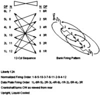 |
Most people look at tabulated V-12 firing orders with a degree of confusion and dismay. Not only does it first appear that the 12-cylinder sequence is random, the nomenclature often obstructs by introducing numbering schemes and letters such as A, B, L, R, D, G to describe the left and right banks. Also, manufacturers assign the number one cylinder location differently; it maybe either next to the propeller, or at the anti-propeller end. Additionally, the engine might be either upright or inverted!
In an effort to make V-12 firing orders comparable, the author uses a naming convention adapted from the German V-12 manufacturers. Beginning at the propeller, cylinders 1-6 are in the right bank, and 7-12 on the left. This applies whether the engine is upright or inverted. With this convention it is also necessary to know the direction of rotation of the crankshaft, either CW or CCW, as viewed from the engine's anti-propeller end. This resolves the complexity of direct drive or geared, and removes confusion caused by the characteristics of different types of gear systems, such as internal or external spur gears, or epicyclic. Note that engine data plates typically use a proprietary manufacturer nomenclature, as well as describing only the direction of rotation of the propeller.
|
©2004, Daniel D. Whitney, Orangevale, California
Instructions
1. Select an engine from the pull down menu at the center of the applet canvas.
2. View the characteristics of that particular firing order.
Display Description
The left diagram depicts the 12-cylinder firing sequence. The columns of numbers closest to the graphic (labeled "N") represent the normalized cylinder numbering scheme. The two outer columns (labeled "DP") represent the data plate cylinder numbering scheme.
The center diagram uses a crankshaft isometric view to depict the engine's bank firing sequence. The small arrow at the crankshaft front indicates the direction of CRANKSHAFT (not propeller) rotation. Note that in all cases the crankshaft has a 6-throw, 120° configuration with crankpins pairs 1-6, 2-5, and 3-4 in the same planes. The arrows depict the firing order of a single bank. Other considerations aside, it is desirable for bank firing sequences to alternate from one end of the engine to the other. This improves engine breathing and exhaust scavenging . The bank firing sequence graphic facilitates visualization of intake and exhaust flows.
The right diagram promotes crankpin loading order visualization. This is an important factor in vibration reduction. A good example is the Junkers Jumo 213. The three examples (213, 213 with Rechlin order, and 213E) show how changes in firing order made a reliable engine out of one that was breaking crankshafts. The problem was too many torque reversals per cycle. This was cured in the 213E by choosing a firing order that systematically loaded and then unloaded the crankshaft.
This tool works for any 12-cylinder engine with cylinder pairs connected to the same crankpin of a 6-throw, 120° crankshaft, regardless of bank angle. Because of this, several opposed and H-configuration engines are included.