Fluid Coupling on the Wright TC18 Power Recovery Turbine
by Tom Fey
Published 20 Nov 2022; Revised 21 Nov 2022
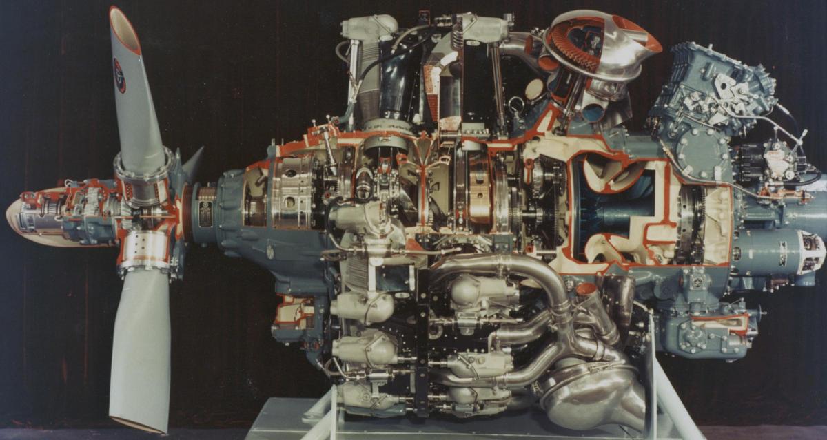
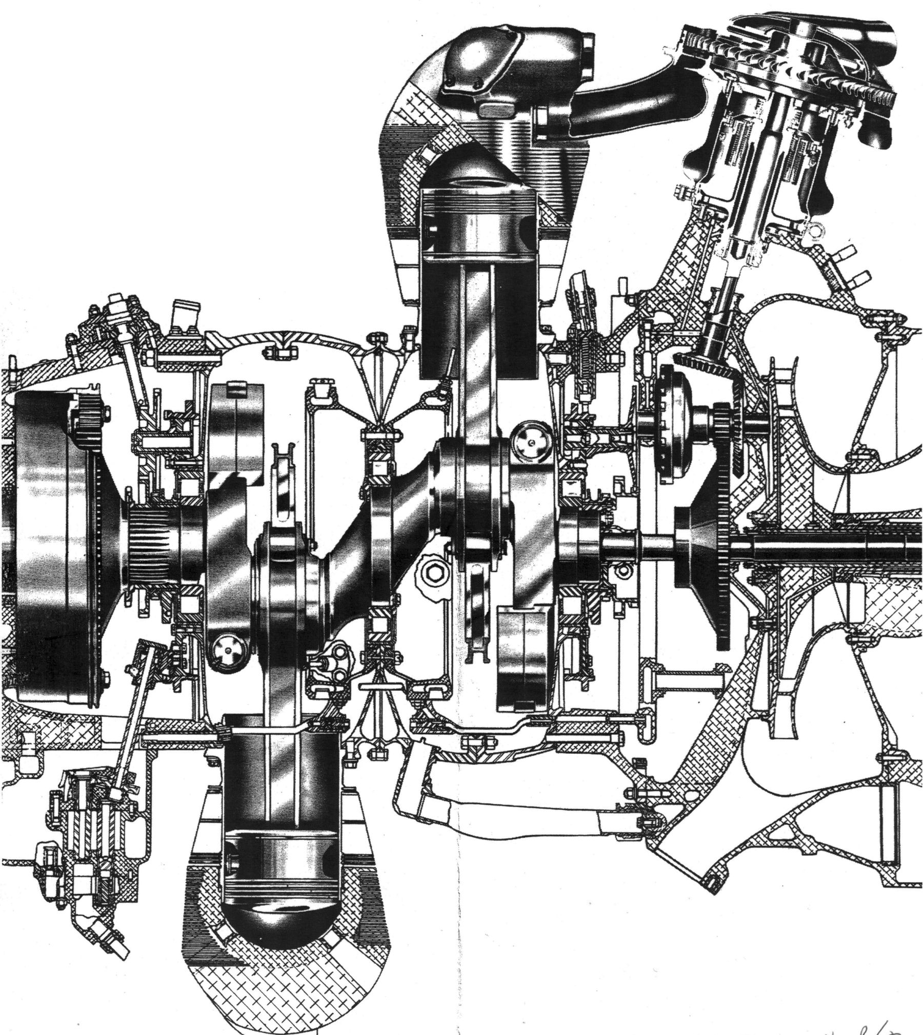
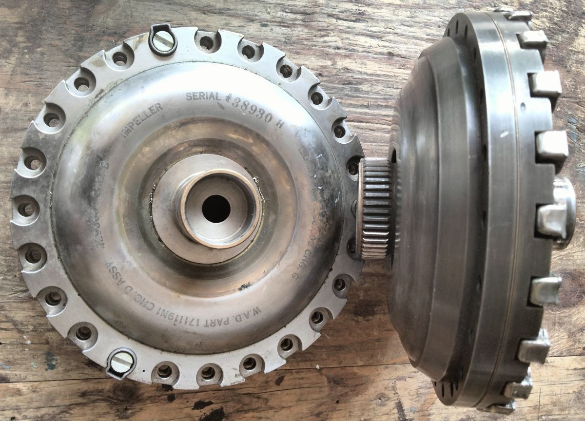
The Wright R-3350 TC18 turbocompound engine of 54.9 liters displacement (Pic 1) is the pinnacle of aviation piston engine technology with unmatched efficiency and a power output that rivaled the mighty 71.5-liter Pratt & Whitney R-4360. The key to the TC18 low specific fuel consumption (sfc =0.39 lb fuel/hp/hr) is the use of turbocompounding in the form of three “blow down” turbines on each engine that convert exhaust gas velocity into horsepower applied directly to the crankshaft (Pic 2). The Power Recovery Turbine (PRT) has been described previously, but an ingenious and essential feature of the PRT system, the fluid coupling, will be described in detail here (Pic 3).
The power recovery turbines and reduction gear train design and packaging were carefully tailored to maximize efficiency at cruise speed where long-distance aircraft spend most of their flight time. The TC18 engines were only 11 inches longer and approximately 540 pounds heavier than the non-turbocompounded R-3350. In return, the PRT’s delivered approximately 180 additional horsepower (10%) per engine in cruise.
|
|
|
| Pic 1. Curtiss-Wright R-3350 TC18 Cutaway | Pic 2. TC18 Longitudinal Section. The PRT and reduction gearing can be seen top right corner between the last row of cylinders and the supercharger. | Pic 3. Fluid coupling laying flat on bench, impeller end up, next to a second coupling on edge with the splined turbine output extending through the cover. |
PRT Power Flow
According to Wright, the PRT’s are spinning at 16,000 rpm in cruise, thus a gear reduction system is required to reduce the output to the 2,400 rpm of the engine. The overall PRT gear reduction ratio is 6.52 to 1, which puts the final PRT output at 2,454 rpm and a close match to the 2,400 rpm engine speed at cruise power.
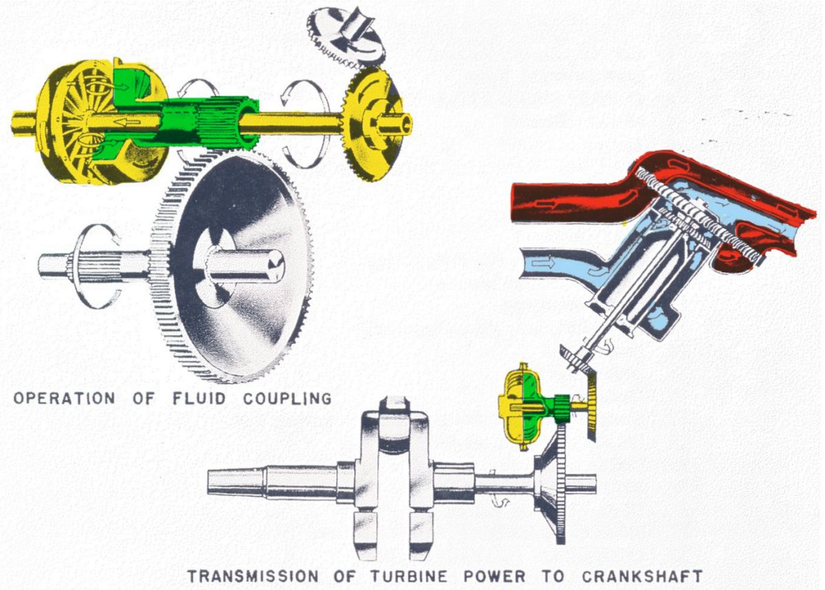
The exhaust-driven power recovery turbine drives a shaft that engages a bevel gear inside the crankcase (Pic 4). This primary bevel gear mates with a secondary bevel gear (yellow) to turn the drive parallel to the axis of the crankshaft. The drive shaft off the secondary bevel gear passes through the center of the coupling output gear to engage the splines of the impeller. The fluid flow inside the coupling drives the turbine (green) whose output surrounds the input shaft and engages a splined pinion gear. The yellow input shaft and green output shaft rotate in the same direction. The green pinion gear drives a large spur gear on the crankshaft/supercharger drive shaft (Pic 5).
 |
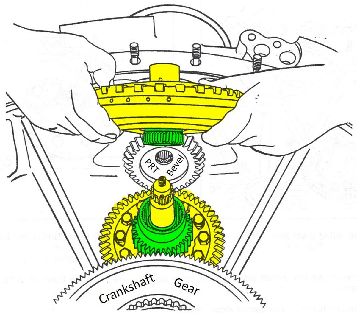 |
| Pic 4. Diagram of the PRT power flow. Input from PRT in yellow drives the impeller side of the fluid coupling. The green turbine outputs power to the final 4.4:1 reduction gear on the crankshaft. | Pic 5. Colorized drawing from the Wright TC18EA Overhaul Instructions showing the fluid coupling being removed. Input from PRT in yellow. The green turbine spline outputs power through a pinion to the reduction gear on the crankshaft. |
Why the need for a PRT fluid coupling?
The rapid but intermittent pulsing of exhaust gases against the turbine blading produces micro-accelerations/decelerations in the wheel as well as shocks and vibration of various frequencies into the PRT drive train. The main job of the fluid coupling is to dampen these vibrations to prevent harmonic interactions that would damage or destroy the PRT drive train. And just as important, the coupling prevents the transmission of vibration from the PRT into the crankshaft/reciprocating/supercharging components of the engine power section. The fluid coupling also allows the PRTs to be inactive for engine starting and buffers oscillations in power transmission between the PRT and the crankshaft.
Video Explaining Fluid Coupling Operation
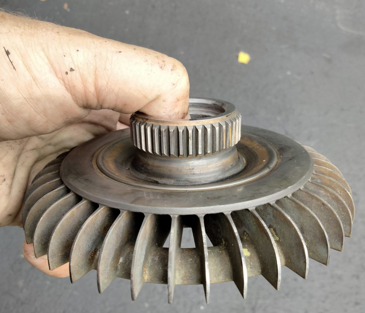
The fluid coupling can be thought of as two close-fitting, opposing fans with no physical connection between them except for the fluid medium. In this case of the TC18, the working fluid is engine oil supplied at 50 psi (Pic 6). The PRT drives the “pump” half of the coupling which Wright terms the impeller, and the attached cover (Pic 7). The opposing “fan”, enclosed by the impeller and cover, is driven by the fluid flow is termed the turbine or runner (Pic 8). All parts of a fluid coupling are matched and balanced at factory assembly and must not be interchanged with other coupling parts. The various parts for a particular coupling are stamped with a mating number, and these mating numbers must be aligned when the coupling is assembled. Any substitution of parts requires a balancing procedure which understandable considering the 10,000+ rpm running speed.
 |
 |
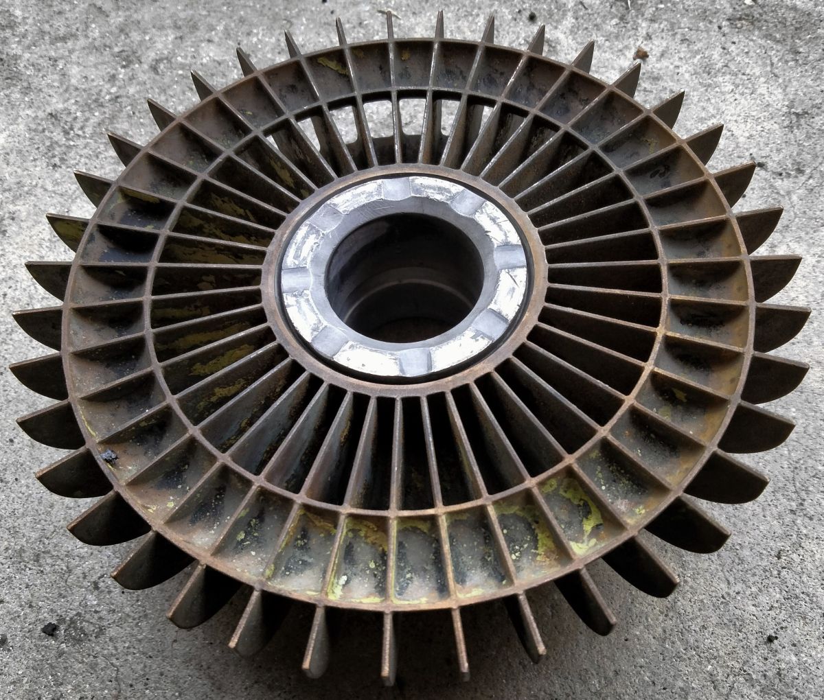 |
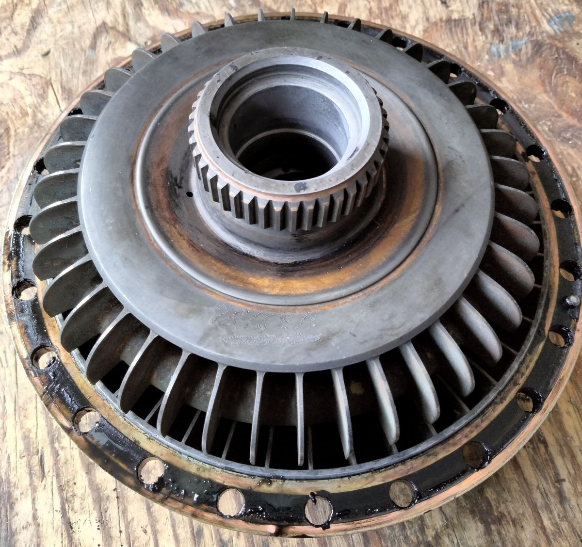
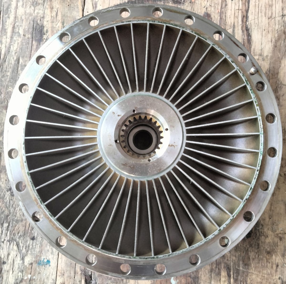
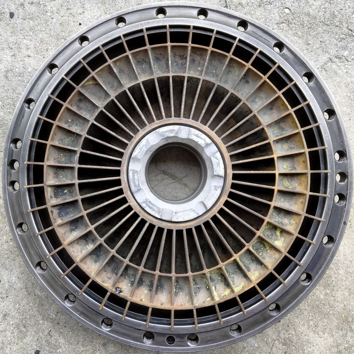
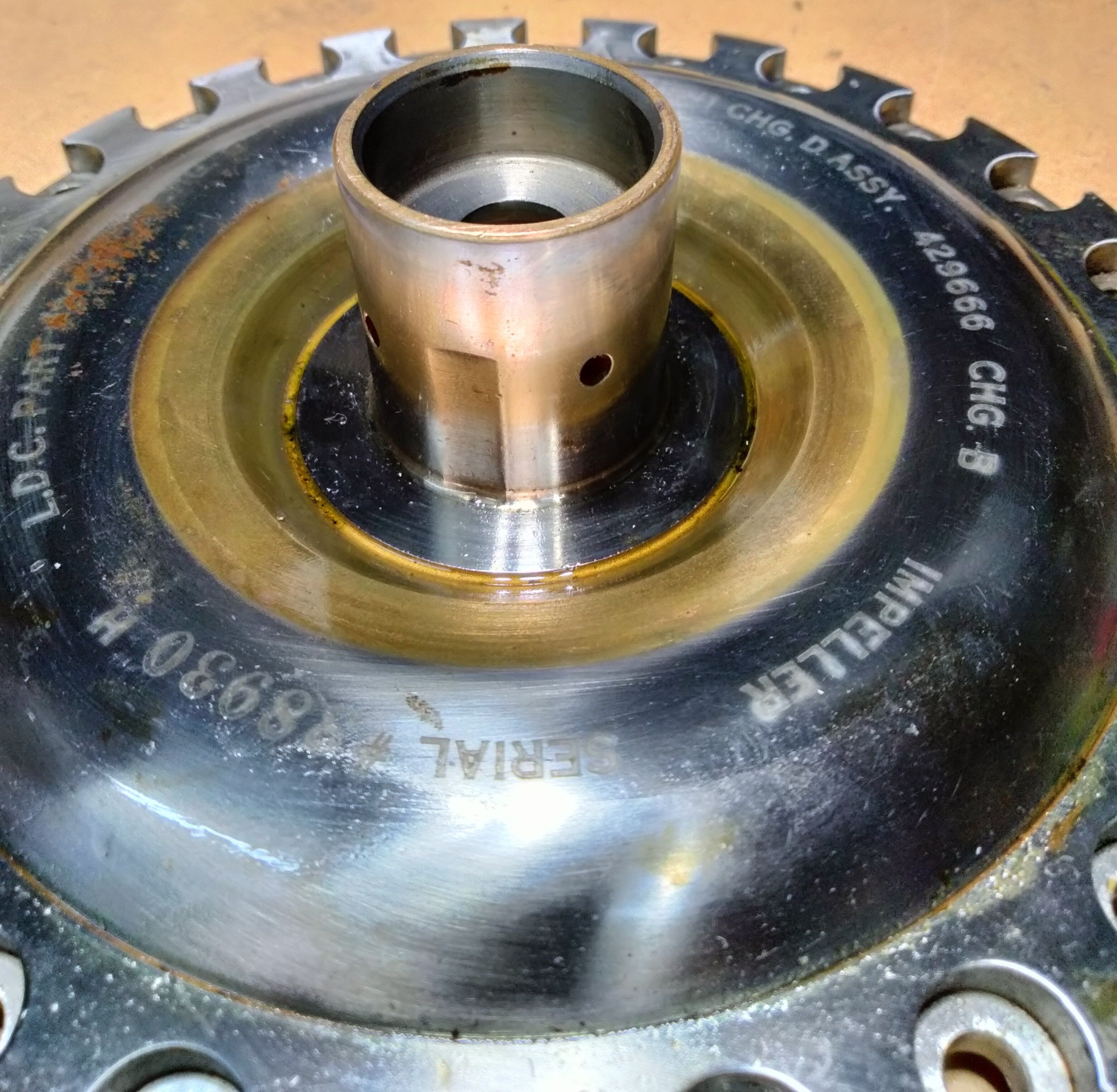
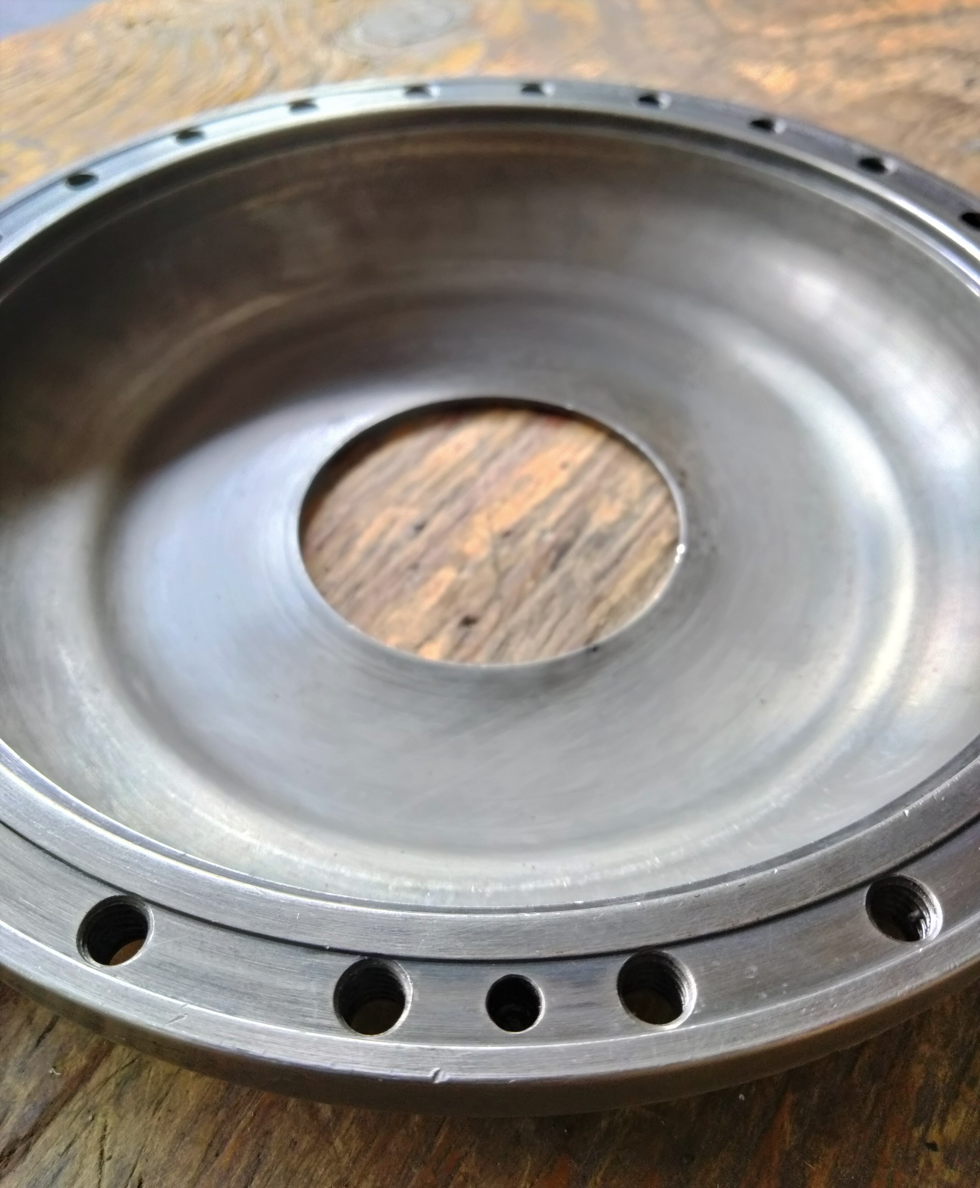
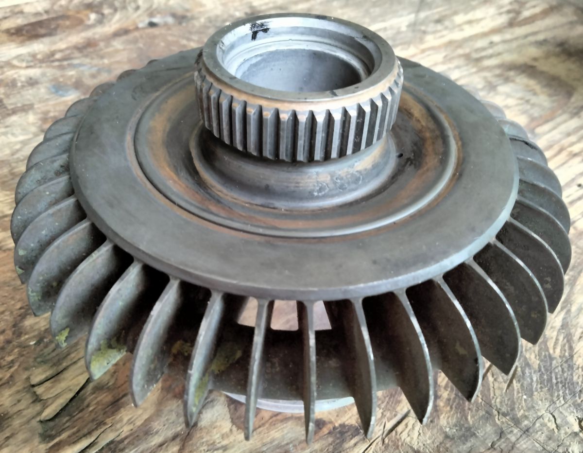
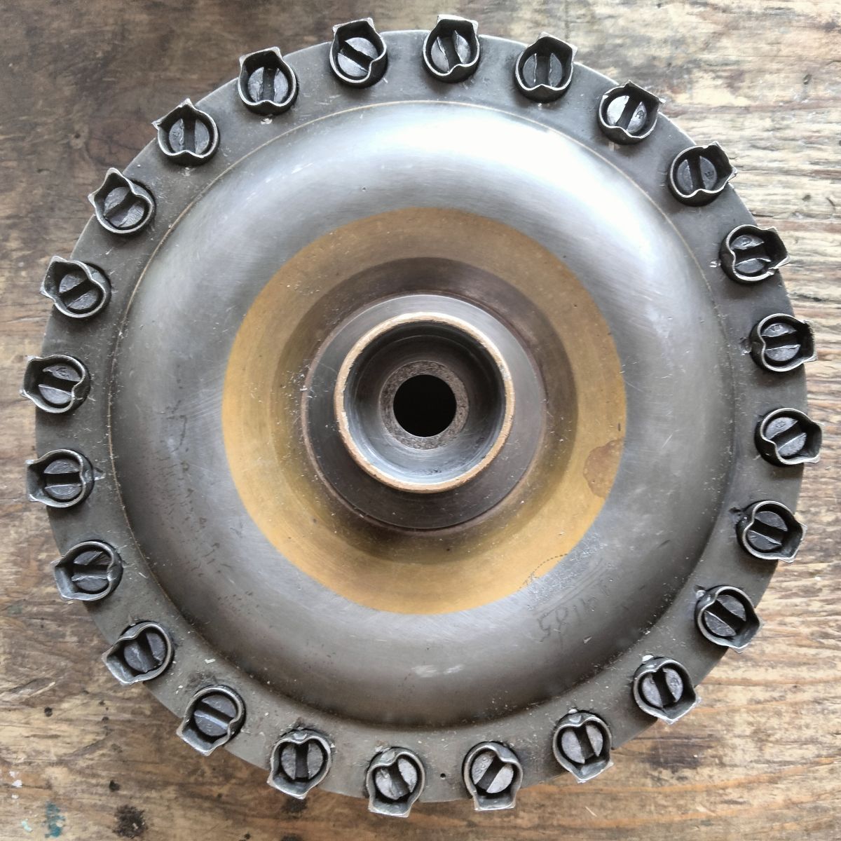
| Pic 6. With the cover removed, the fluid coupling turbine is shown atop the impeller representing the assembled configuration. | Pic 7. Fluid coupling impeller. Oil is introduced via the bearing journal, through the four holes near the center, with oil exiting into the vane spaces located at 11, 2, 5, an 8 o’clock. | Pic 8. Fluid coupling turbine. Note the scalloped reliefs in the center bearing face as well as the open channels visible at 12 o’clock that provide oil recirculation back to the impeller. |
The one-piece impeller weighs 2.37 lb (1,073 gr) and has 42 individual radial vanes. The turbine has 39 radial vanes and weighs 1.54 lb (699 gr). The cover which encloses the turbine weighs 1.5 lb (677 gr) (Pic 9, Pic 10). The impeller, turbine, and cover are steel and the assembly is 6.3" in diameter and 1.9" thick at the torus. The fluid coupling (impeller, turbine, cover, copper gaskets, screws and locking cups), devoid of oil and without the input drive shaft and output pinion gear, weighs 5.8 lb (2.6 kg), which is remarkable as each fluid coupling can transmit up to 150 horsepower at takeoff power.
 |
 |
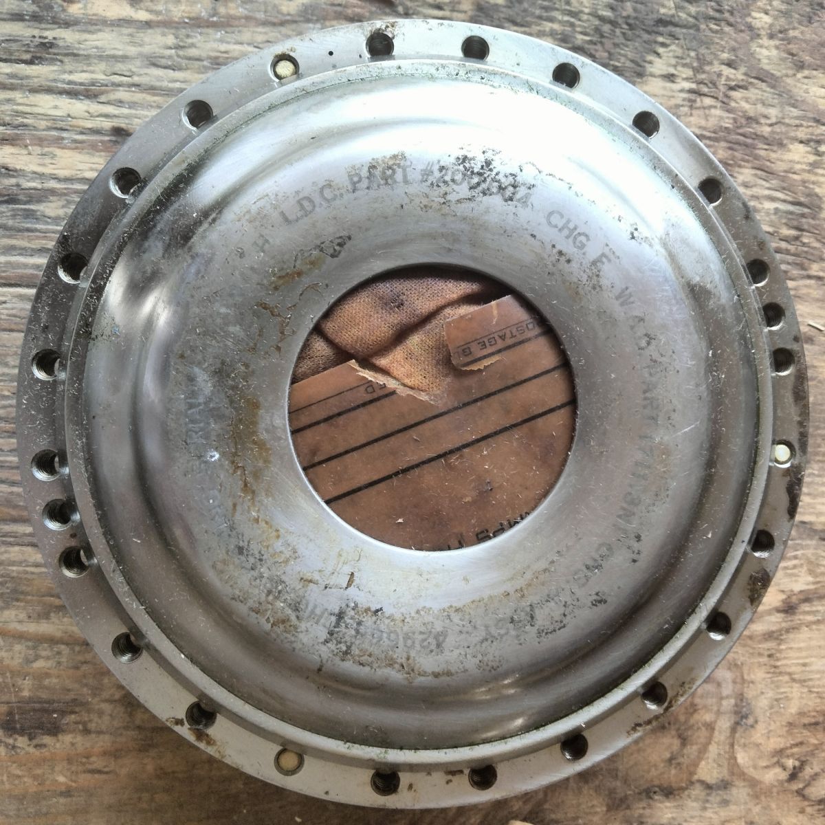
| Pic 9. External view of the fluid coupling cover. When assembled, the turbine output spline projects from the center hole in the cover. | Pic 10. Turbine shown in place inside the fluid coupling cover. |
The one-piece impeller is the forward component of the coupling. A cylindrical journal on the fore impeller face seats in a silver-backed, steel plain bearing fixed in the PRT support frame in the supercharger front housing (Pic 11). The input driveshaft is splined and bolted to the impeller. Oil is ported from the PRT support, through the bearing into the impeller, through the impeller bore, out through four holes each of 0.055" diameter near the center of the impeller, and thrown outwards by centrifugal force (Pic 12). The first stage of mechanical gear reduction in the PRT system is 1.47:1 by the bevel gears, so the output from the 16,000 rpm turbine is reduced to 10,889 rpm into the impeller. This rotational velocity produces a centrifugal force of 8,419 x g at the inside perimeter of the torus. Directed by the impeller vanes and accelerated radially by centrifugal force, the oil then flows into the opposing turbine. The vanes on the perimeter of the turbine receive the fluid input from the impeller and drives the turbine to 98% the impeller rpm. The turbine, which spins in the same direction as the impeller, rides on a sleeve bearing slipped on the input drive shaft. Mid-span openings in the turbine provide for the recirculation of oil back to the center portion of the impeller (Pic 13). Wright states that there is only 1 – 2% slippage in transmitting turbine power to the crankshaft. A 2% differential would be a 217 rpm (3.6 revolutions per second) difference between the impeller and the turbine. The fluid coupling will generate significant heat in the process of transferring power and this thermal load is carried away by the oil, into the supercharger front housing sump, and into the main oil cooling system.
 |
 |
 |
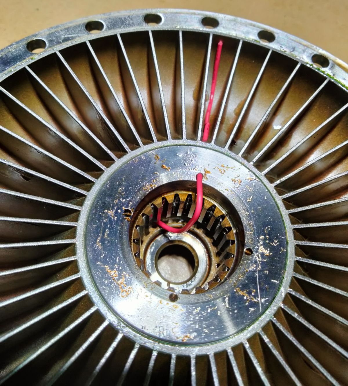
| Pic 11. Impeller bearing journal showing two of the four large ports that transfer oil into the fluid coupling. The rectangular relief in the bearing surface is believed to function as an oil bleed, allowing oil to be flung into the front supercharger section, lubricating the gear train and removing heat. | Pic 12. Impeller with red wire tracing the oil flow path from the bearing through the spline coupling to the vane chamber. Some oil will vent to the impeller center section as well. | Pic 13. Fluid coupling turbine. Note the raised radial lip where the turbine will seal against the cover once pressurized with oil. Output spline at top will mate with a pinion gear to drive the large spur gear on the crankshaft. |
Interestingly, the there is no gasket or seal between the turbine and the cover. The assembly is spaced and shimmed to allow the turbine to translate up to 0.034" (think lawnmower spark plug gap) in end float along the inner driveshaft. This dimension is also the maximum gap separating the impeller from the turbine. When the fluid coupling is pressurized with oil and energized by centrifugal force, the lip on the face of the turbine is pressed backwards against the cover, sealing the fluid coupling (Pic 14, Pic 15). Recall that the impeller and the turbine may be rotating at slightly different rpm, and that everything inside the coupling is bathed in pressurized oil, so this clever method of sealing allows the components to rub past each other with minimal friction. The end float of the turbine allows oil to drain from the fluid coupling when at rest, which is beneficial at start-up because the electric starter motor doesn’t have to spin up the PRTs. Once the engine starts, oil pressure comes up, engine rpm builds, and the fluid coupling will start to transmit power.
 |
 |
| Pic 14. Internal surface of the fluid coupling cover. When pressurized, the lip on the turbine will be pushed against this surface to seal the coupling. | Pic 15. Fluid coupling turbine showing the radial sealing lip and vents visible at 6 o’clock that allow the recirculation of oil back to the impeller. |
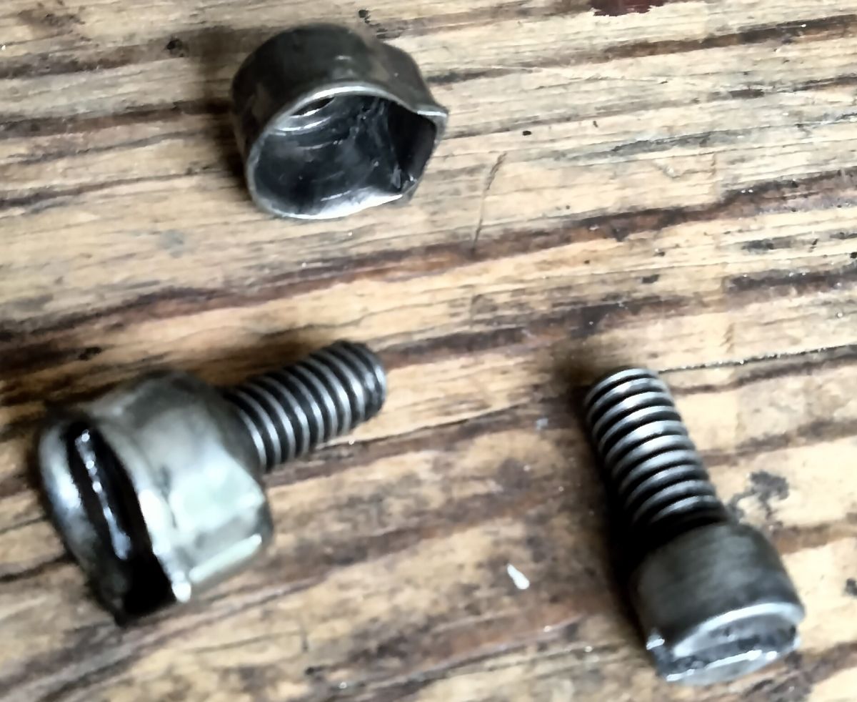
The fluid turbine resides inside the cover opposite the impeller. One or more copper gaskets seal the cover to the impeller, secured by 24 screws. The stainless steel screw locking cups are unique (Pic 16). One side of them is squared to engage a slot machined out of the cover. The screws are submerged in the locking cups. Once the screws are torqued in, the lip of the lock is staked over to engage the screw slot, preventing the screw from backing out (Pic 17).
The fluid turbine has an externally-splined output that exits the central hole in the cover to mate with an internally-splined pinion gear. The pinion gear is located on the input drive shaft. And finally, the pinion gear drives the large spur gear affixed to the crankshaft. The reduction ratio between this final pinion and spur gear is 4.4:1 (Pic 18).
 |
 |
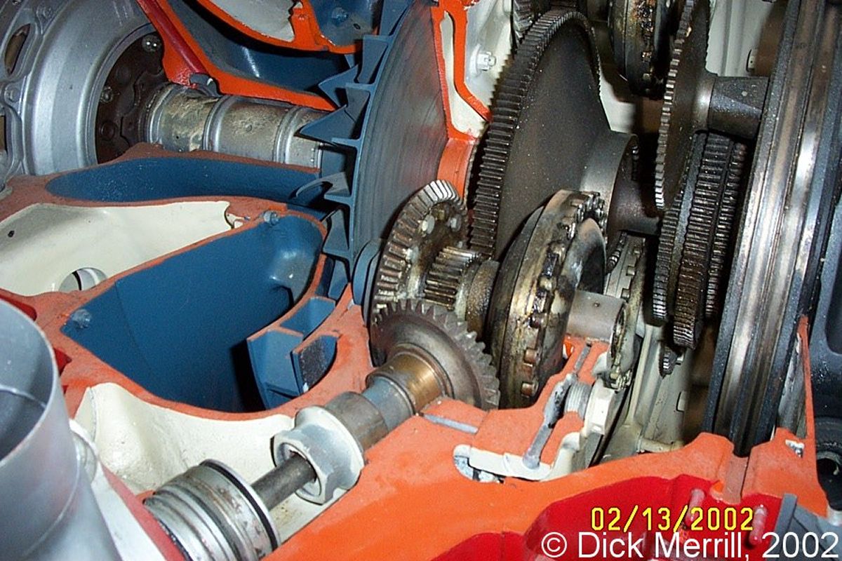 |
| Pic 16. Cheesehead screws and thin, partial square-sided stainless steel screw locking cups that safety lock the fluid coupling cover to the impeller. | Pic 17. Fluid coupling impeller side showing the screws and locks in place. | Pic 18. Photograph by Dick Merrill showing the fluid coupling and reduction gear train in place inside a sectioned TC18 engine. |
The Wright service notes on the TC18 comment that sludge could build up in the early versions of the fluid coupling as well the turbine-to-pinion coupling, however improved vortex flow and re-sculpting of the coupling eliminated areas of low flow, curing the problem.
The Wright turbocompound engines, especially the power recovery turbines, had a bad reputation for eating parts. This was especially true for the earlier versions of the TC18 and is substantiated in airline service reports. But ATP, A&P/IA, and one time owner of three Lockheed L-1649 Starliners, Maurice Roundy, stated the reason for some of this reputation was that the airlines were pushing the TC18s really hard, running hours at METO (Maximum Except Take Off) power in an effort to remain competitive with the new jet aircraft coming into operation. Certainly the military EC-121 Warning Star radar picket aircraft shouldered a significant load during the patrolling the sea lanes and gathering intelligence during the Cold War as well as directing air operations in the Vietnam War. According to Roundy, if the engines were run according to the manual and climb profiles adhered to, the TC18 engines and PRTs became very reliable.
Acknowledgements
My gratitude to AEHS member Mike Nixon for the TC18 fluid coupling.
Send mail to
![]() with questions or comments about this web site.
with questions or comments about this web site.
![]()