Pratt & Whitney Wasp Major (R-4360)
Compiled by Kimble D. McCutcheon
Published 29 Oct 2001; Revised 12 Jun 2025
|
The Pratt & Whitney R-4360 "Wasp Major" was the largest aircraft piston engine to be mass produced in the United States. Although it found extensive military application, its 28 cylinders, 56 manually-adjustable valves, and 56 spark plugs prevented it from finding favor with the airlines. |
Wasp Major Description
Type = 28-cylinder four-row air-cooled, radial
Bore = 5.750" Stroke = 6.000" Displacement = 4,362.5 in³
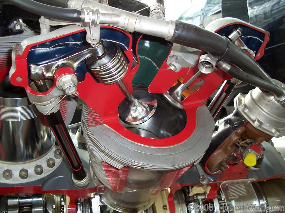
Cylinders were built up of forged aluminum heads with deep-cut cooling fins and integral valve mechanism housings, screwed and shrunk onto forged steel cylinder barrels. Forged aluminum sleeves into which deep-cut cooling fins were been machined (muffs), were shrunk on over the cylinder barrels . Each cylinder has one inlet and one exhaust valve, both seating in steel inserts. The cylinders are arranged helically around the crankcase and pressure baffles are provided for individual cylinders. For each bank of four cylinders hooded baffles insure adequate cooling to all cylinders. All cylinders are completely interchangeable.
Forged aluminum pistons are of the full-skirt type and feature reinforced internal pin bosses. Each piston is fitted with three compression rings, dual oil control rings and one oil scraper ring. The top compression ring is chromium plated on the face that
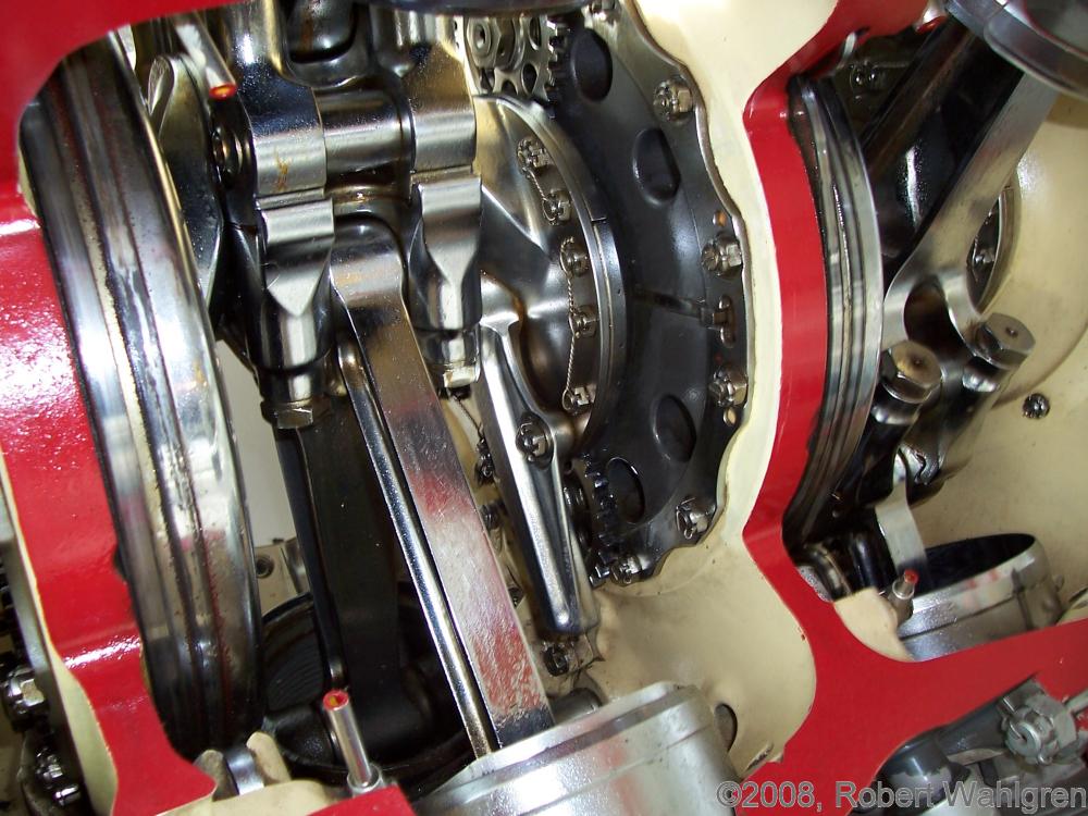
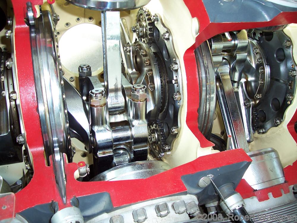
The master rod for each row of seven cylinders has a cap that captures a keyed two-piece lead-silver bearing. Six "I" section articulated rods, each with bronze bushings at either end are attached to the master rod via silver-plated knuckle pins.
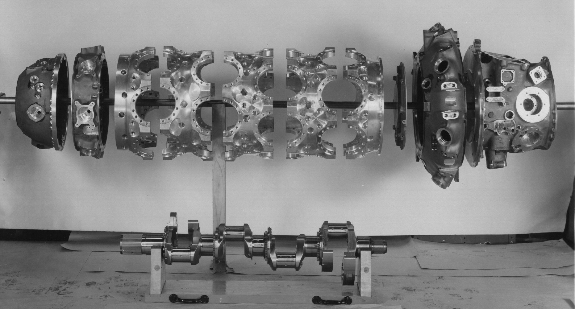
A one-piece forged steel crankshaft is forged steel. It has four throws and is supported in the crankcase by five steel-backed lead-silver main bearings. Four counterweights counteract the rotating and reciprocating masses. Two of these weights are fixed, while the remaining two employ bifilar dynamic vibration absorbers.
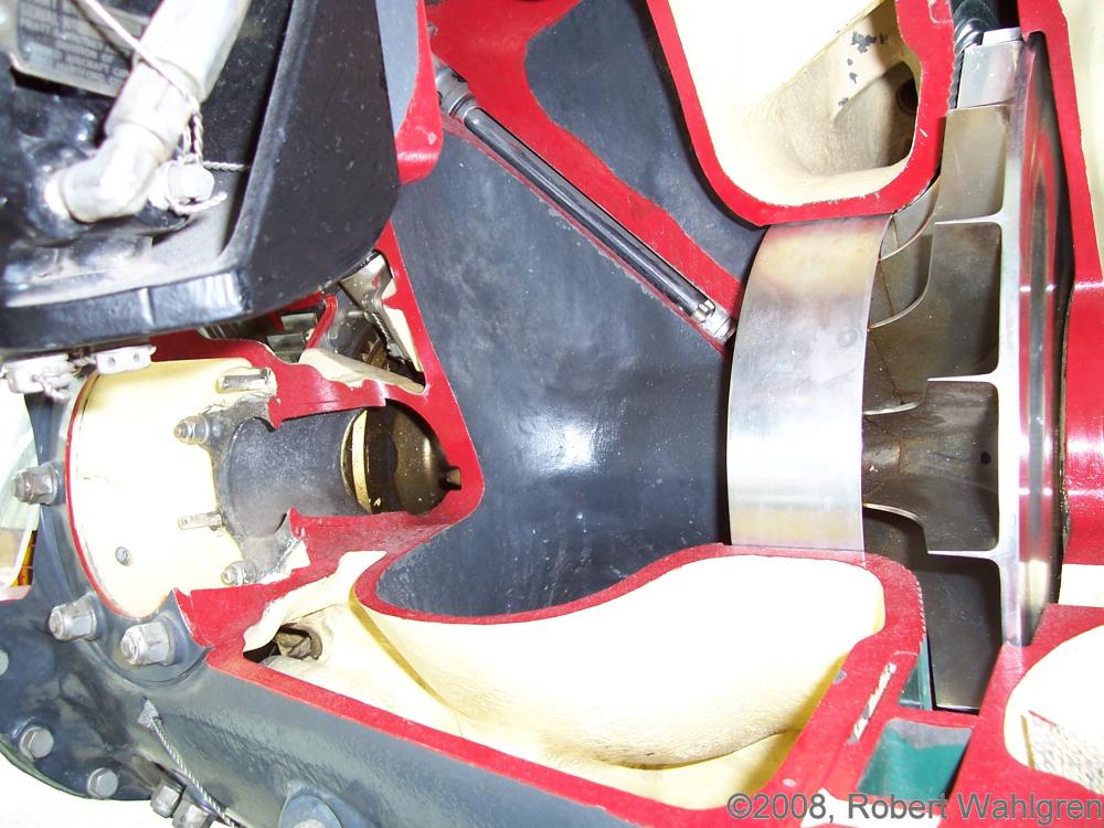
The propeller shift is supported at the crankshaft end by a plain lead-bronze bearing and at the propeller end by a roller bearing to carry radial loads and a deep-groove ball bearing to carry thrust loads.
The crankcase power section is composed of five sections, and all except the front and rear sections are substantially alike. Power section parts are machined from aluminum forgings and are held together with through bolts. All other crankcase sections are magnesium castings.
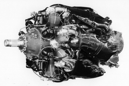
The magneto section, attached to the power section front, contains a torquemeter and mounting pads for seven magnetos (early engines) or four magnetos (later engines).
The nose section, mounted forward of the magneto section, houses the planetary reduction gearing and has provisions for full-feathering reversible propeller governor. Reduction gear ratios are either 0.375 or 0.425.
The supercharger housing, attached to the power section rear, contains the supercharger impeller, diffuser and drive gearing.
The accessory section, located behind the supercharger housing, supports a downdraft pressure carburetor and also houses accessory drives to radially-mounted accessories. This permits greater servicing accessibility as nothing is mounted to the engine rear.
The valve gear consists of rocker boxes, integral with the cylinder heads, that extend fore and aft. These contain rocker arms that are actuated by enclosed push rods and tappets running on double-track shelf-mounted cam rings inside the crankcase between cylinder rows. These operate exhaust valves on the row forward and intake on the row aft. The cams are driven by spur gear trains at 1/6 crankshaft speed.
Induction is achieved by a four-barrel Stromberg pressure carburetor with automatic mixture control and idle cutoff. Also provided is primer tubing and mixture distribution. Metered fuel is carried through internal passages to the supercharger impeller, where it is thrown centrifugally through small holes between impeller blades. This fuel/air mixture, after passing through the impeller and diffuser, is carried to the cylinders through seven intake pipes, one for each bank of four cylinders.
Superchargers fall into two broad categories. Single-stage single-speed superchargers are used in conjunction with turbosuperchargers, and single-stage hydraulically-driven variable-speed units are used for non-turbocharged applications.
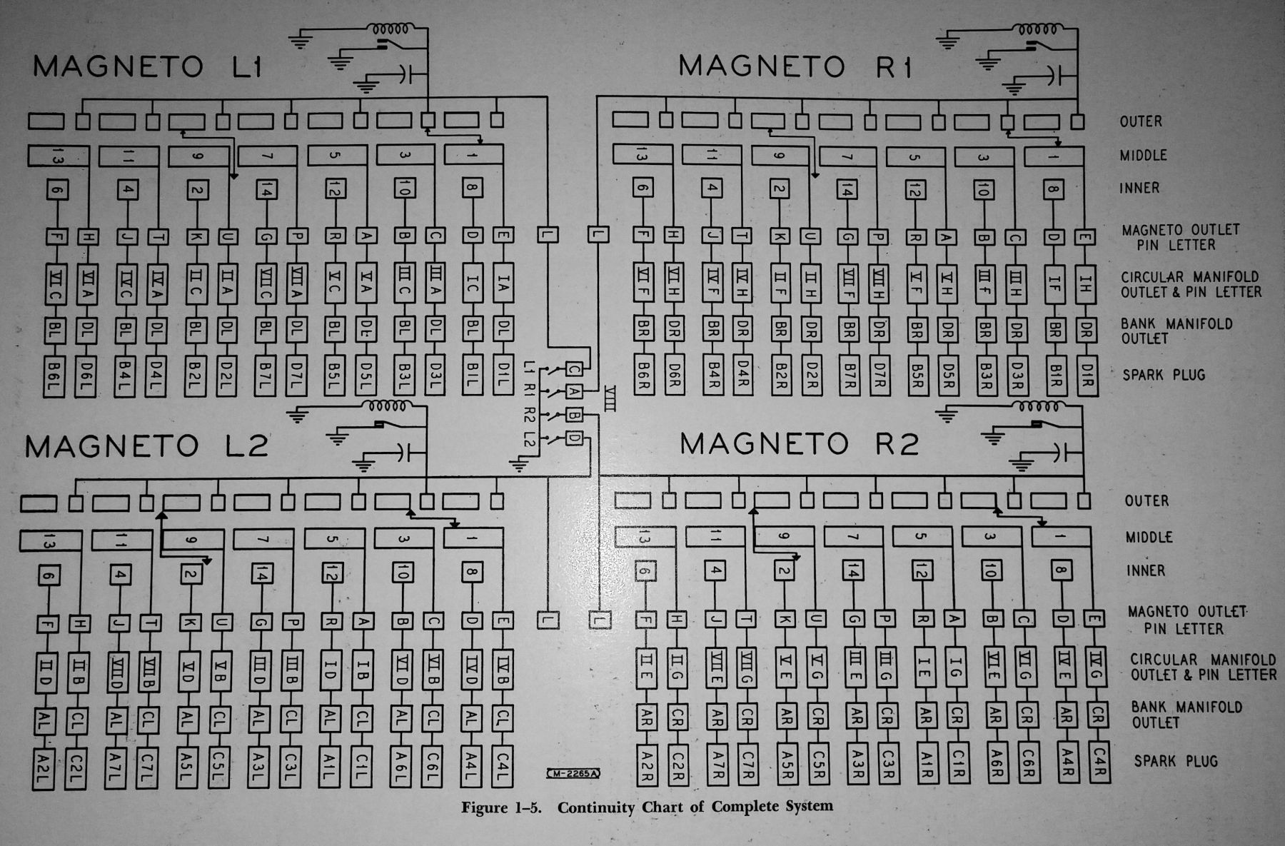 |
| P&W R-4360 C-Series Ignition System Map (Robert Wahlgren) |
The ignition system on early engines consists of seven pressurized Bendix Scintilla D4RN-2 high-tension shielded magnetos with integral distributors operating at 1/2 crankshaft speed. Each magneto provides dual ignition for a bank of four cylinders directly behind it. Later engines use four Bendix Scintilla S14RN-15 low-tension magnetos with integral distributors operating at 1/2 crankshaft speed. Magnetos on the engine's left side are designated L1 and L2; L1, the top-left magneto, fires the intake plugs on cylinder rows B and D; L2, the bottom-left magneto, fires the intake plugs on cylinder rows A and C. Magnetos on the engine's right side are designated R1 and R2; R1, the top-right magneto, fires the exhaust plugs on cylinder rows B and D; R2 the bottom-right magneto fires the exhaust plugs on cylinder rows A and C.
Lubrication to all engine parts is provided by a gear-type oil pump.
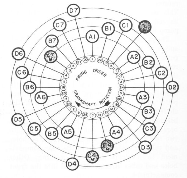
R-4360 Firing Order
Cylinder rows are designated A through D from anti-propeller end to propeller end. Cylinder banks are designated 1 through 7, with numbers increasing clockwise, cylinder 1 being the topmost cylinder. Master rods are located in cylinders A7, B4, C4 and D1.
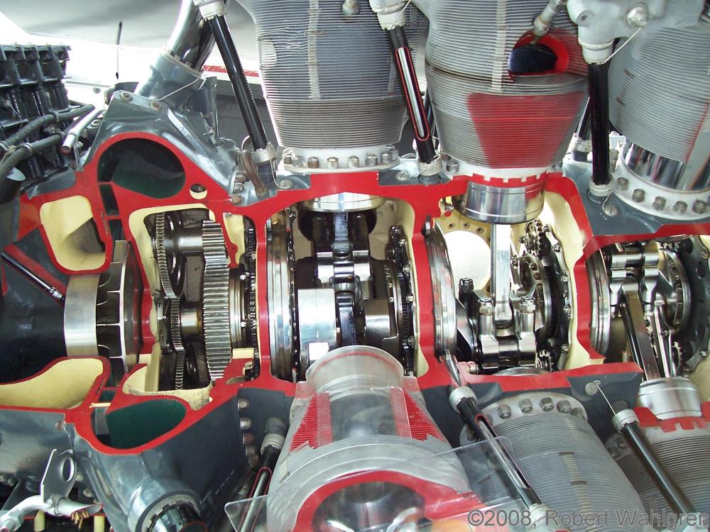
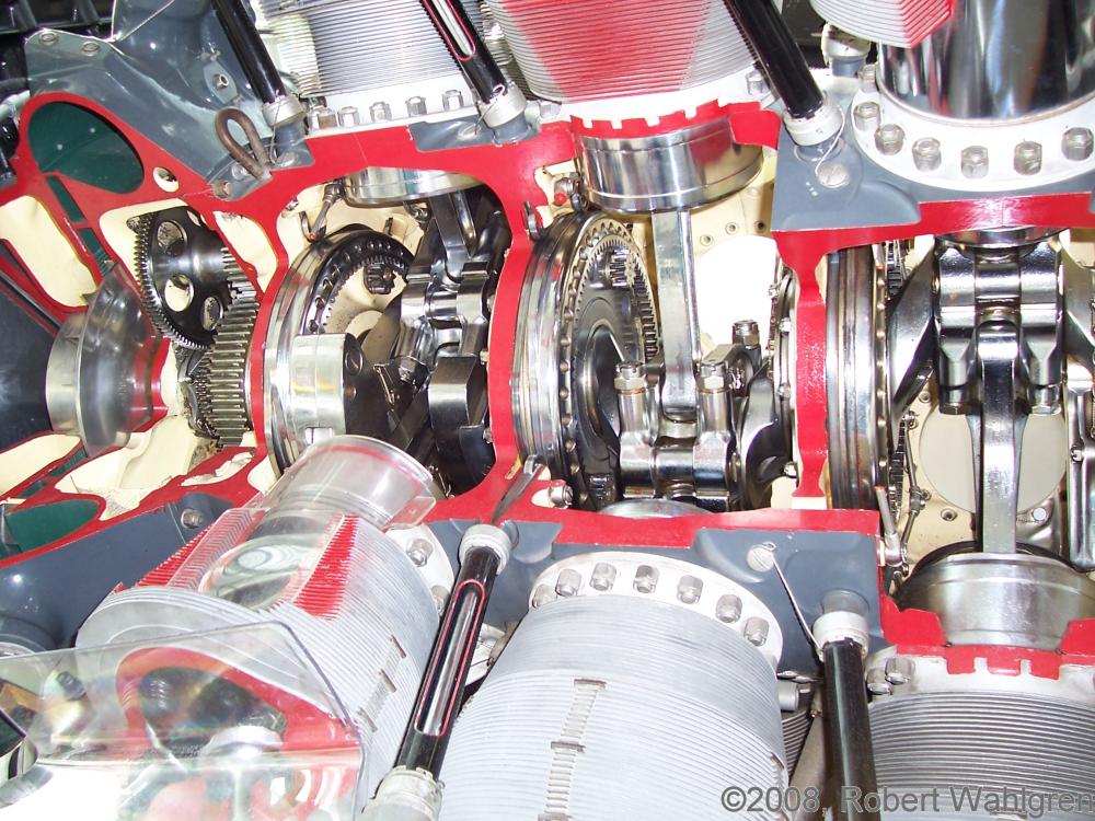
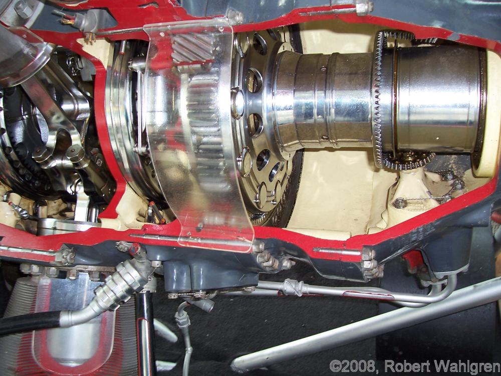
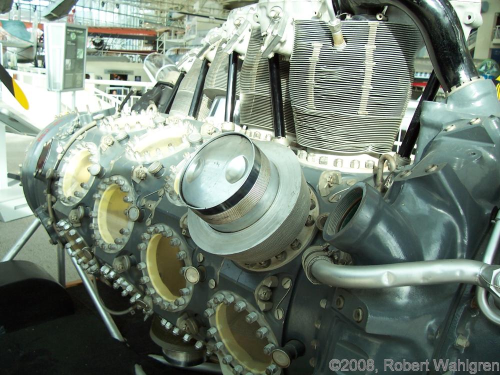
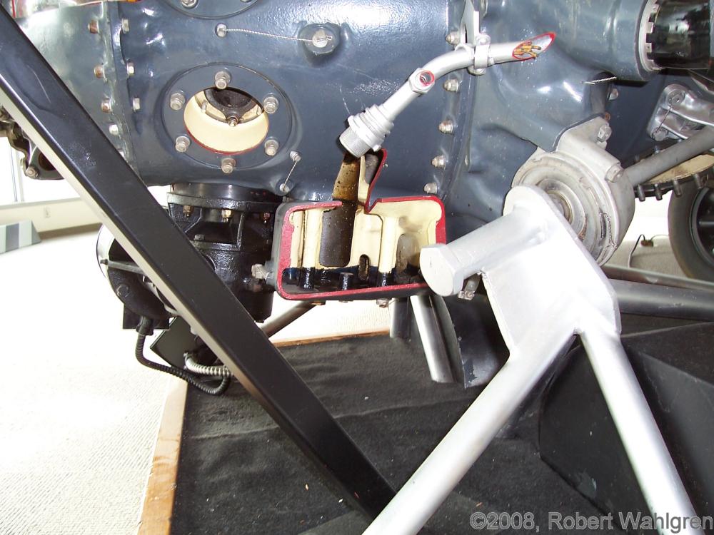
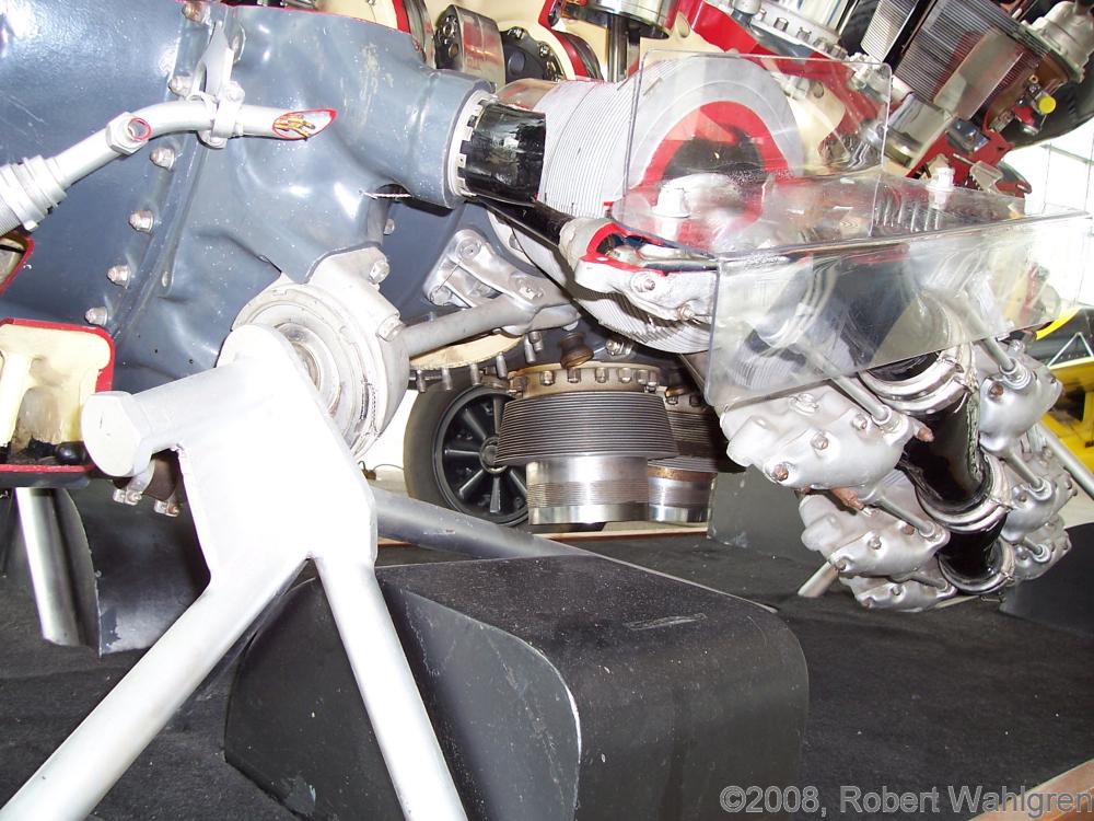
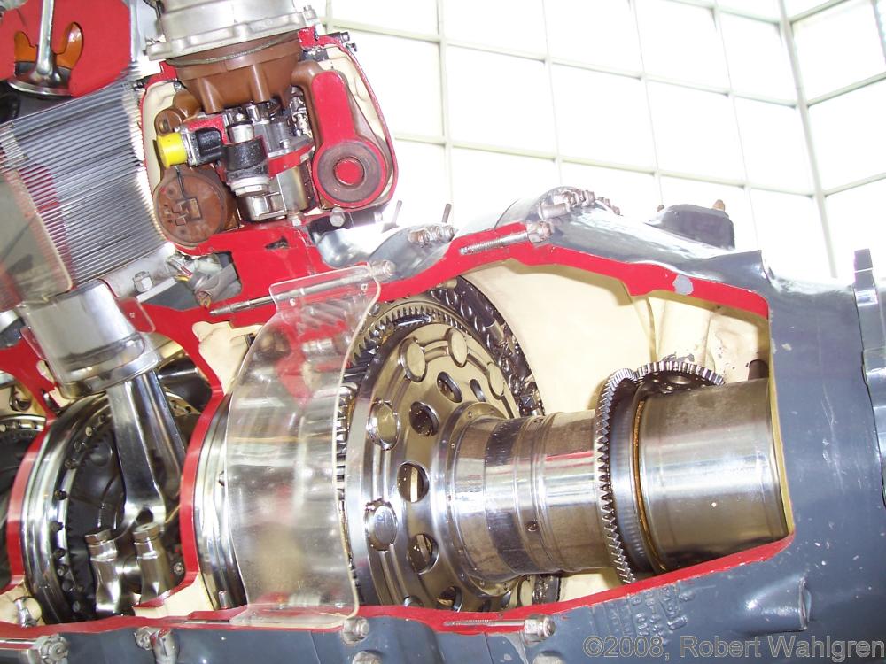
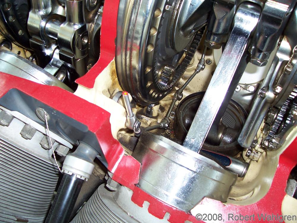
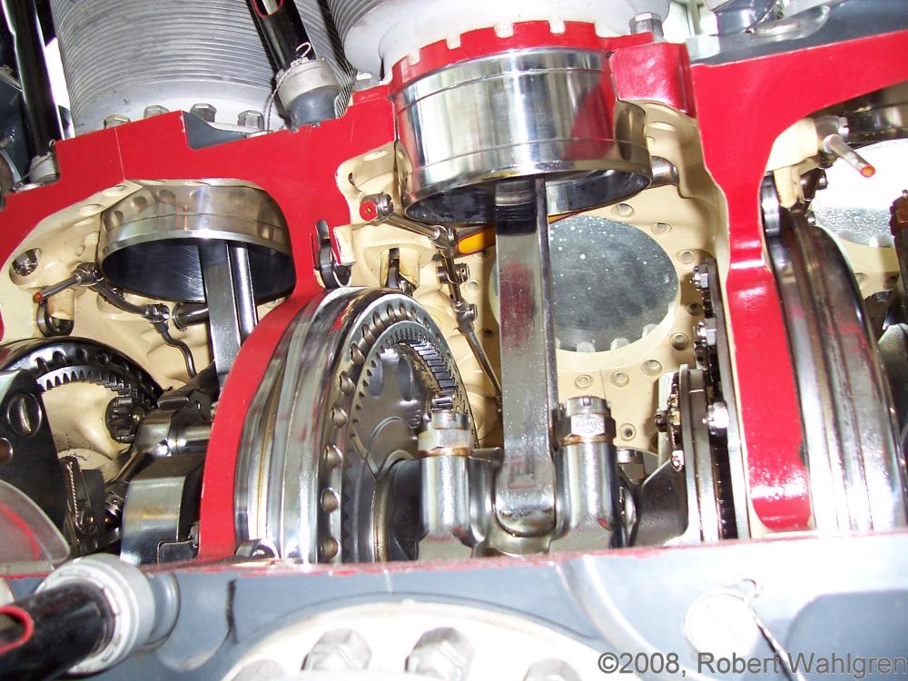
R-4360 Cutaway at the
Museum of Flight, Seattle, Washington
Submitted by Robert Wahlgren
 |
 |
 |
 |
 |
 |
 |
 |
 |
 |
 |
 |
 |
 |
 |
 |
 |
 |
 |
 |
 |
 |
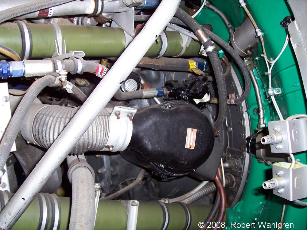 |
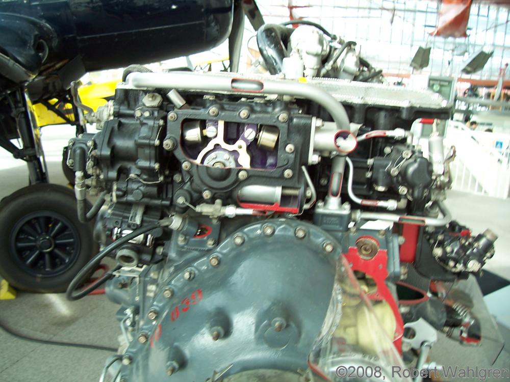
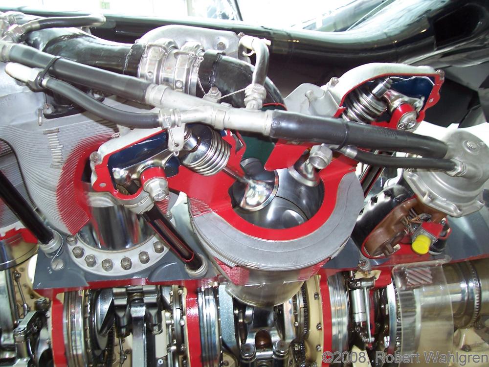
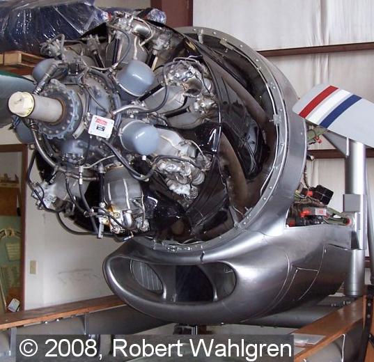
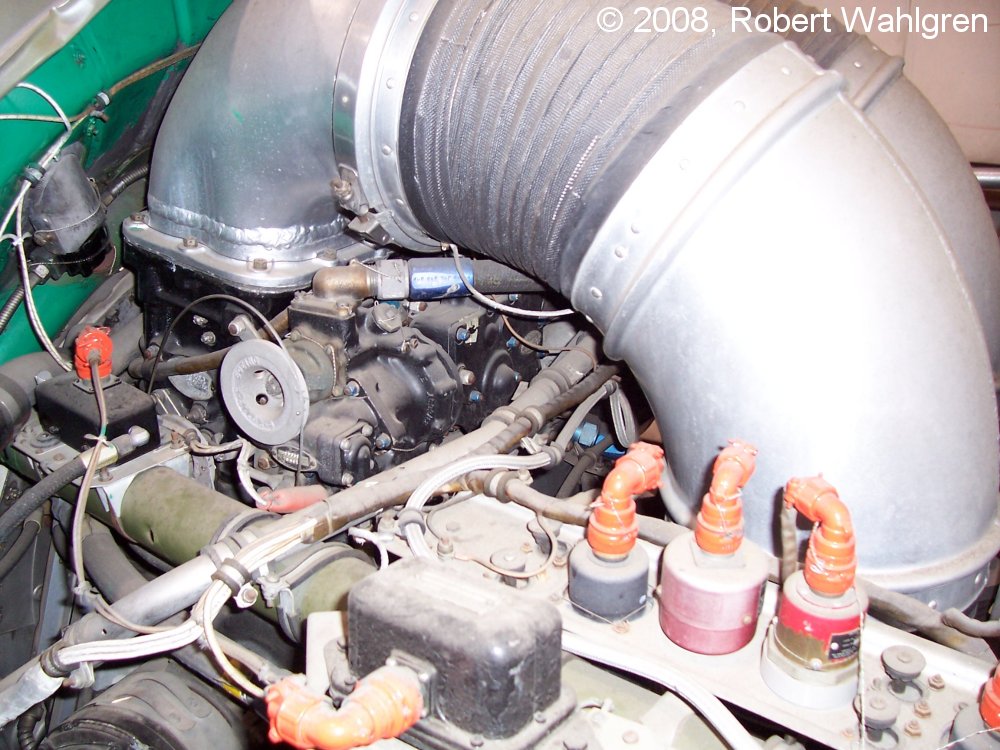
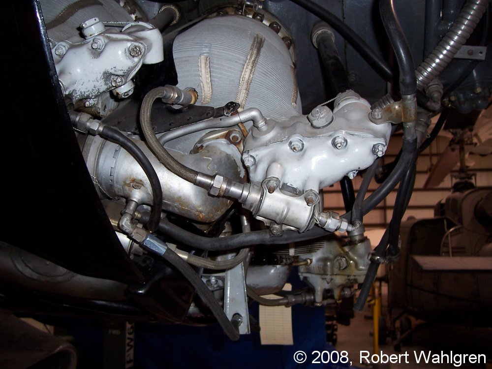
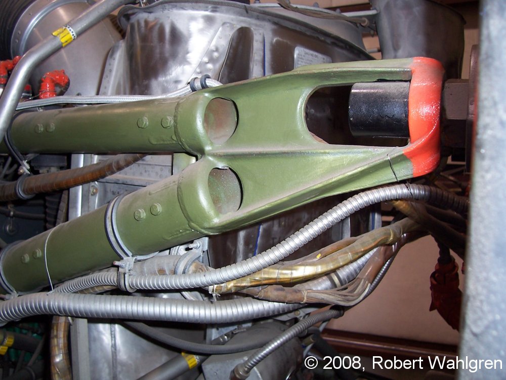
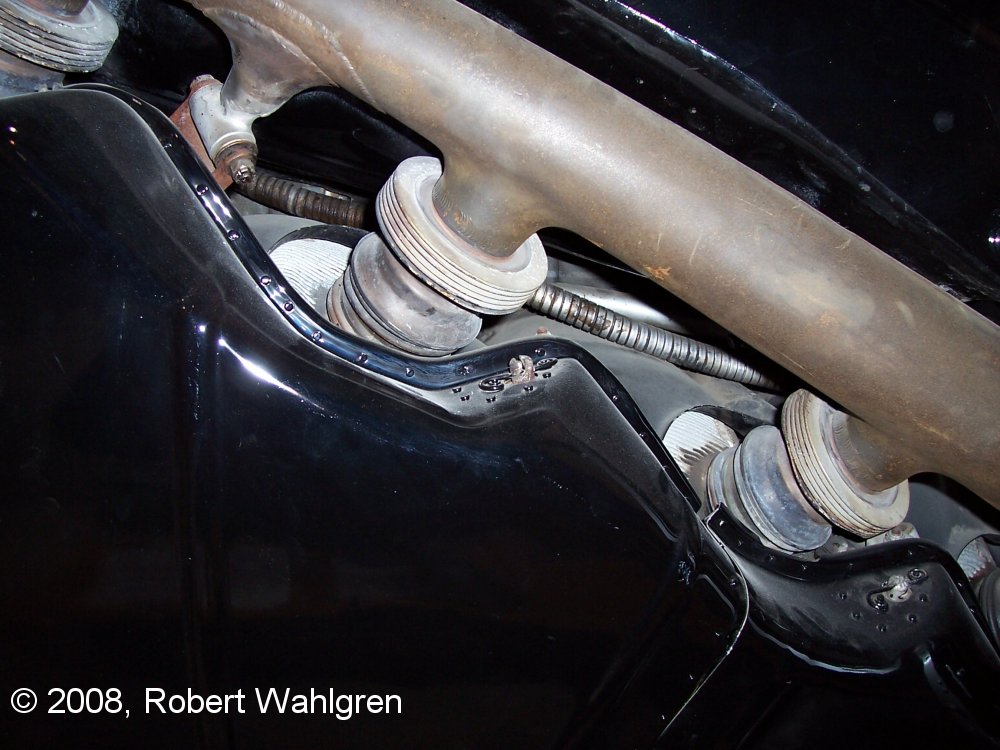
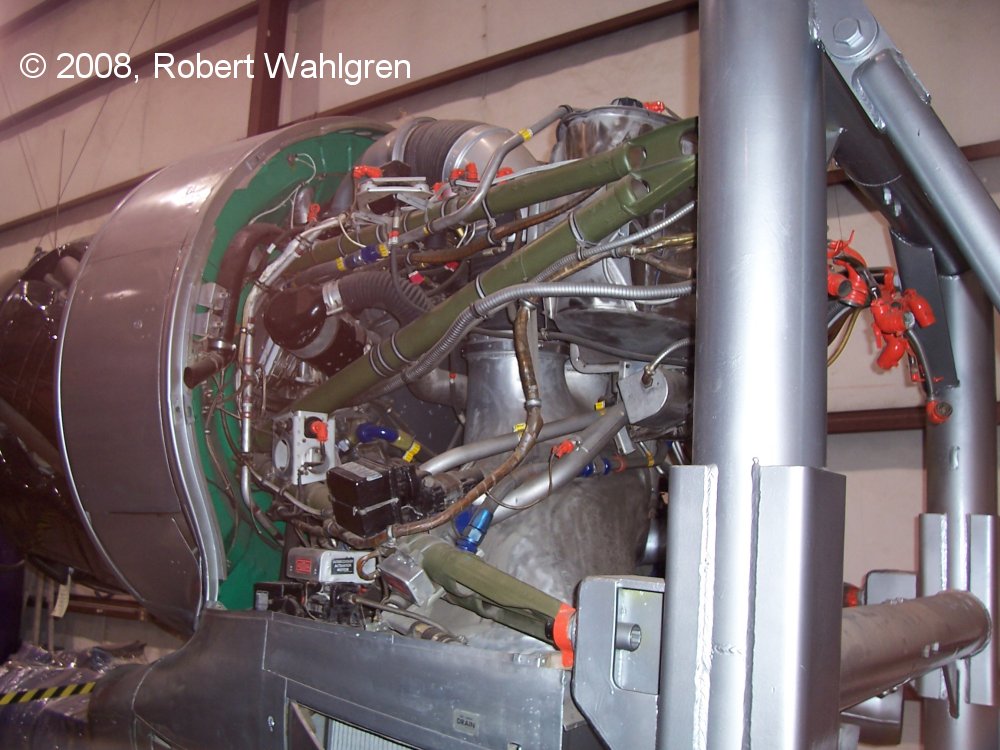
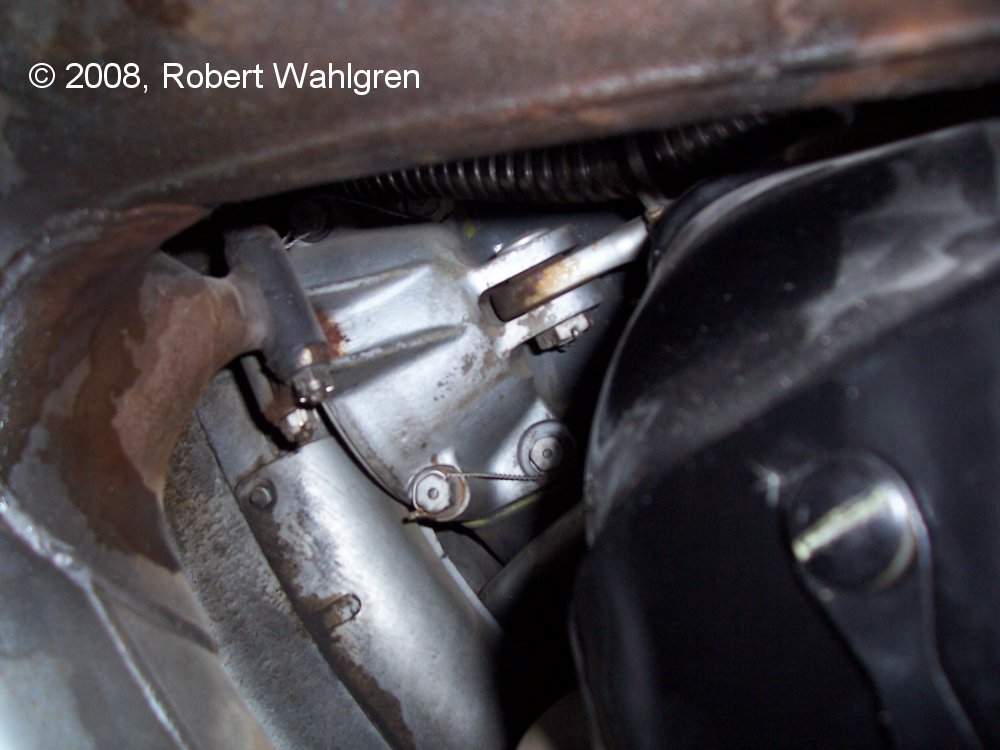
| QEC on Boeing maintenance stand, propeller is on right | Carburetor and induction piping | Cylinder and intake manifold with oil drain hose | Left upper engine mount to airframe attach point | Exhaust manifold | Left rear showing generator and cowl flap motor | Engine mount to case | Right side showing generator with cooling hose, starter under it and fire detection sensors |
C-97 QEC, R-4360-59B Specifications
Courtesy of Robert S. Wahlgren
| Weight with propeller | 7,988 lb |
| Weight without propeller | 6,500 lb |
| Bore | 5.75" |
| Stroke | 6.00" |
| Displacement | 4,360 in³ |
| Compression Ratio | 6.7:1 |
| Propeller Shaft Rotation | Clockwise, 0.375:1 ratio |
| Spline size | 60-A |
| Maximum dry weight | 3,691 lb |
| Diameter | 55.0" |
| Length | 96.5" |
| CG from main crankcase rear face | 18.4" |
| CG at crankshaft | @ Centerline |
| Impeller diameter | 14" |
| Impeller Ratio | 6.375:1 |
| Carburetor | Bendix PR100B3-4 |
| Magneto | Bendix Scintilla S14RN-15 |
| Magneto Ratio | 0.5:1 |
| Spark plug gap | 0.011" - 0.014" |
| Spark Advance Normal | 20° BTC |
| Spark Advance Cruise | 30° BTC |
| Cam Timing | |
| Intake Opens | 64° BTC |
| Intake Closes | 76° ABC |
| Exhaust Opens | 135° BBC |
| Exhaust Closes | 79° ATC |
| Intake Duration | 320° |
| Exhaust Duration | 394° |
| Overlap | 143° |
| Cold valve clearance, not incorporating overhaul change 273 | |
| Intake | 0.040" |
| Exhaust | 0.025" |
| Cold valve clearance incorporating overhaul change 273 | |
| Intake | 0.035" |
| Exhaust | 0.035" |
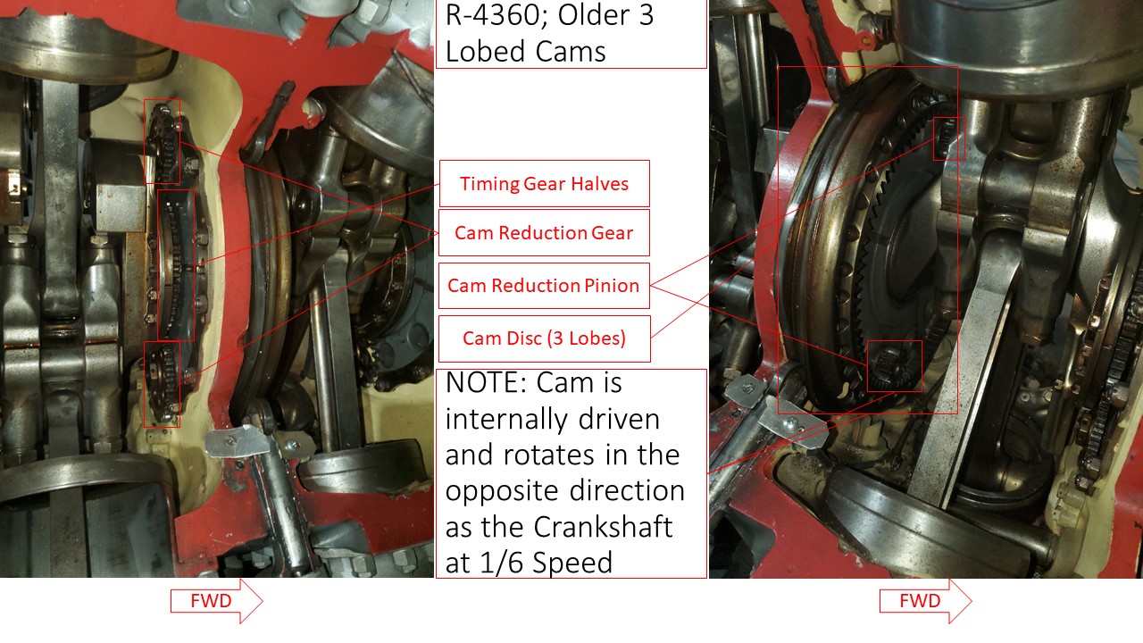
R-4360 Cam Drive Evolution
by Michael Smith
Radial engine designers have some choice about the number of cam ring lobes and direction of cam rotation.
If X is the number of lobes, Y is the number of cylinders and R the speed ratio, then:
For cams rotating opposite the crankshaft direction, X = (Y - 1) / 2 and 1 / R = 1 / (Y - 1).
For cams rotating the same as the crankshaft direction, X' = (Y + 1) / 2 and 1 / R' = 1 / (Y + 1).
The Pratt & Whitney R-4360 used two cam drive schemes, which are illustrated by cutaway engines in the Museum of Aviation at Robins Air Force Base, Georgia.
 |
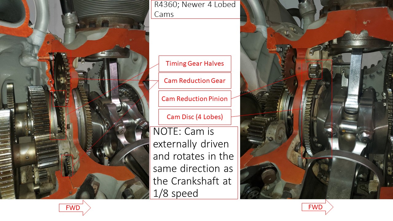 |
| Early 3-Lobe Cam | Later 4-Lobe Cam |
Index of Wasp Major and R-4360 Designated Engines (568K Acrobat File)
Wasp Major Development History
History of the R-4360 (764K Acrobat File)
R-4360 Service History for C-97 and KC-97 Aircraft in Air National Guard Units
Lockheed Model 89 Turbosupercharger Trade Studies
R-4360 Gallery (Warning! Large Files)
 |
 |
 |
 |
 |
 |
 |
||
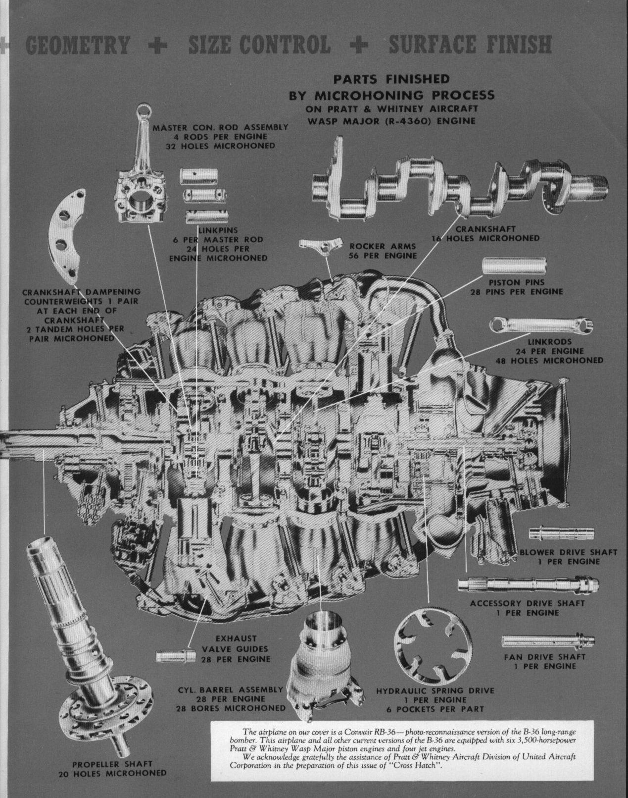
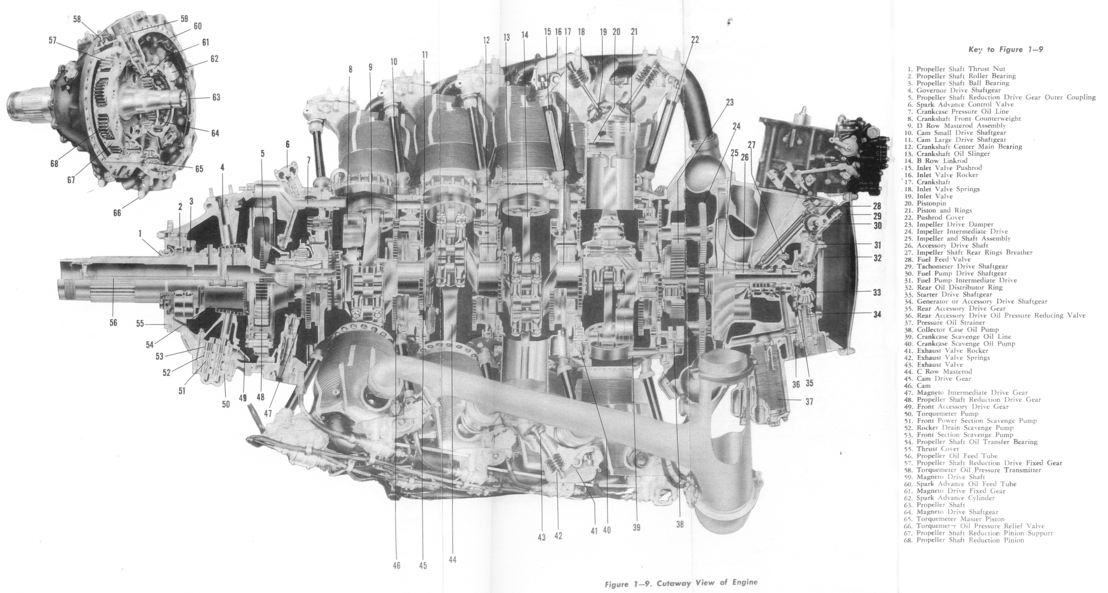
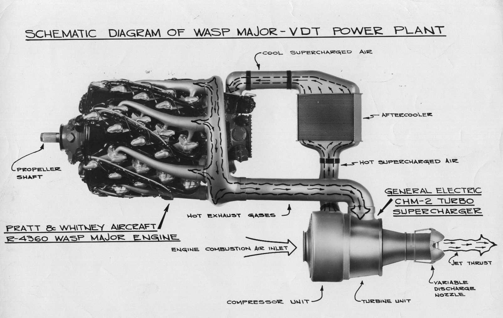
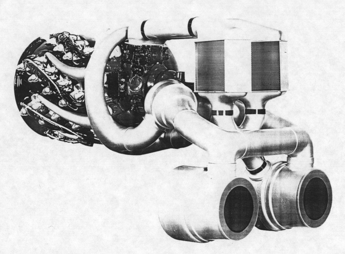
| Crankcase and Crankshaft | Part Finishing Processes | Cross Section | VDT Schematic The Variable Discharge Turbocharger (VDT) concept was meant to produce over 4,000 HP and allow piston-powered airliners to fly non-stop from Chicago to London. |
VDT 3/4 Rear View Exhaust ducts, intake ducts, turbochargers and aftercooler dwarf the already large R-4360 engine |
R-4360 with Remote Gearbox This fan-cooled engine with a remotely-mounted propeller reduction gear was used in the Northrop XB-35 "Flying Wing." |
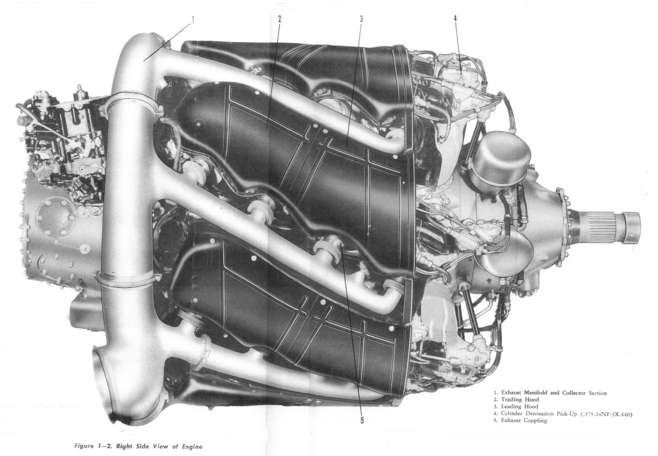
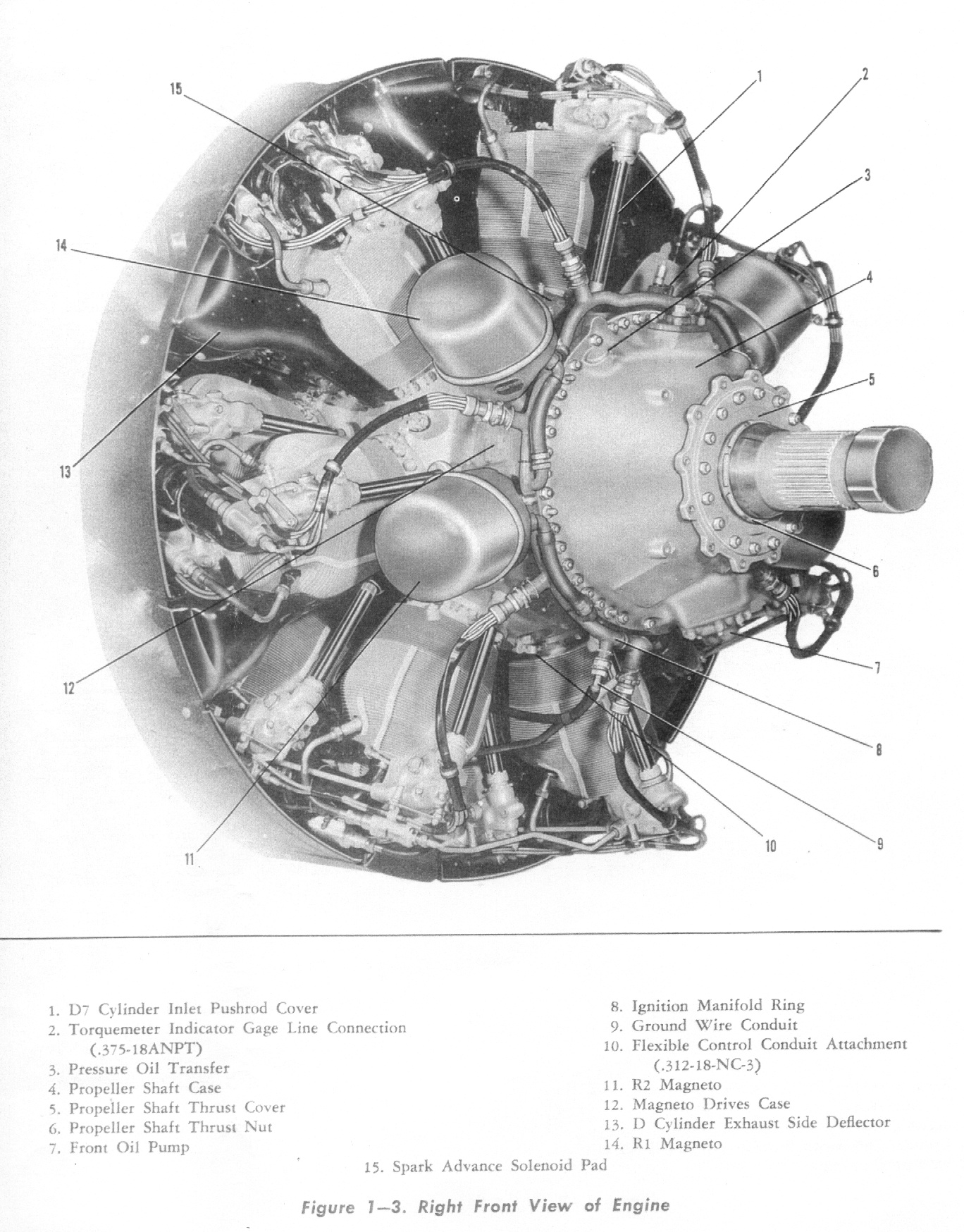
Right Side | Right Front | B6 Oil Flow |
Send mail to
![]() with questions or comments about this web site.
with questions or comments about this web site.
![]()