Pratt & Whitney Hornet A, C, D, E (R-1690)
Compiled by Kimble D. McCutcheon
Published 6 May 2020
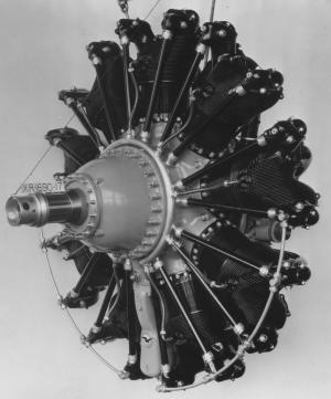
Pratt & Whitney XR-1690-17 Hornet
(P&WA) |
The nine-cylinder Pratt & Whitney Hornet was a larger version of the Wasp that first ran on 16 Jun 1926 and the first production engine was delivered to the U.S. Navy on 24 Mar 1927.
With a normal rating of 525 hp at 1,900 rpm, the Hornet was direct competition for the Wright R-1750, which was in production from 1927 until 1930. The Hornet's numerous applications included the Boeing 40B, Boeing 80, Boeing 95, Curtiss YA-10, Douglas O-38, Focke Wulf Condor, General Aviation C14B, General Aviation GA-43, Great Lakes TG-1, Hamilton UC-89, Junkers 152, Junkers JU-86, Keystone B-3A, Keystone C2H, Keystone XLB3A, Keystone LB7, Lockheed 14-H2, Lockheed 18-H, Lockheed C-56, Lockheed C-59, Lockheed R50-2, Lockheed XR40-1, Martin 74, Martin B-12, Martin T4M, Martin P3M-2, Sikorsky JRS-1, Sikorsky OA-8, Sikorsky Y10A-8, Sikorsky S-40A, Sikorsky S-42, Sikorsky S-43, Thomas Morse YO-2G, Vought G3U-2, Vought SU-1, Vought SU-2, Vought SU-3, Vought SU-4, Vought V-80P and Vought V92S.
Pratt & Whitney and its licensees produced 2,944 Hornet and R-1690 designated engines between 1927 and 1943. |
Hornet Description
Type = 9-Cylinder Air-Cooled Radial
Bore = 6.125 " Stroke = 6.375 " Displacement = 1,690.5 in³
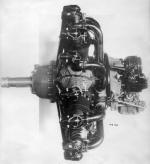
The Pratt & Whitney Hornet features a solid master connecting rod, two-piece crankshaft, forged aluminum crankcase, enclosed valve gear, built-in supercharger, and all accessories grouped at the rear.
The main crankcase is divided into two similar sections in the cylinder plane that are united by nine through bolts between the cylinders, as well as by the cylinder flanges. With this construction the explosion forces are equally distributed between two main bearings, one in each case section.
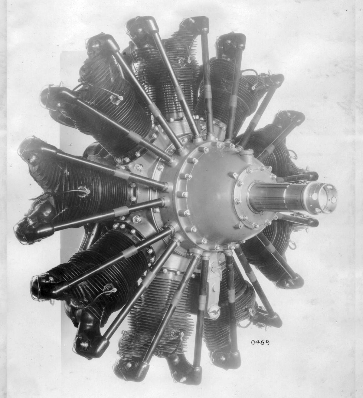
The nose section is hemispherical in shape. It carries a deep-row ball bearing that transmits propeller tthrust from the shaft to the engine mounting via the crankcase. The valve tappets are also carried in the nose section, which encloses the cams and their operating mechanism.
The blower or mounting section supports the engine in the airplane and is attached to the rear of the main case. The supercharger, together with its gearing, is carried in the blower section. The mixture is fed into an annulus from the impeller and thence to the cylinders by means of tangential pipes. The rear or accessory case section is attached to the blower section and carries all accessories, including two magnetos, a starter, a fuel pump, a carburetor, oil pumps, oil strainers, oil relief valve, tachometer drive, and two synchronizer drives. Provision is also made for mounting and driving a generator.
The blower and rear sections form an assembly that may be removed from the main case as a unit, without disturbing any of the accessories or their gearing. Likewise, the main and nose sections may be removed as a unit with the cylinders in place, leaving the blower and rear sections attached to the airplane.
The crankshaft is made in two pieces and is supported on two roller bearings on each side of the crankpin and one ball bearing just behind the propeller hub. The crankpin is integral with the crankshaft forward section, which transmits power to the propeller hub. The splined rear crankshaft section telescopes into mating crankpin splines, and is carried completely through it. The two crankshaft sections are united by a through bolt and kept in the proper angular relation by splines.
The solid master connecting rod makes possible higher crank speeds than are possible with two-piece rods. Babbit-lined big end bushings are inserted in the rod and bear directly on the crankpin. Eight I section link rods are attached to the master rod by means of knuckle pins. Each rod is bronze bushed for the piston and knuckle pins. Oil is carried under pressure to the big end bearing, and also to the knuckle pins.
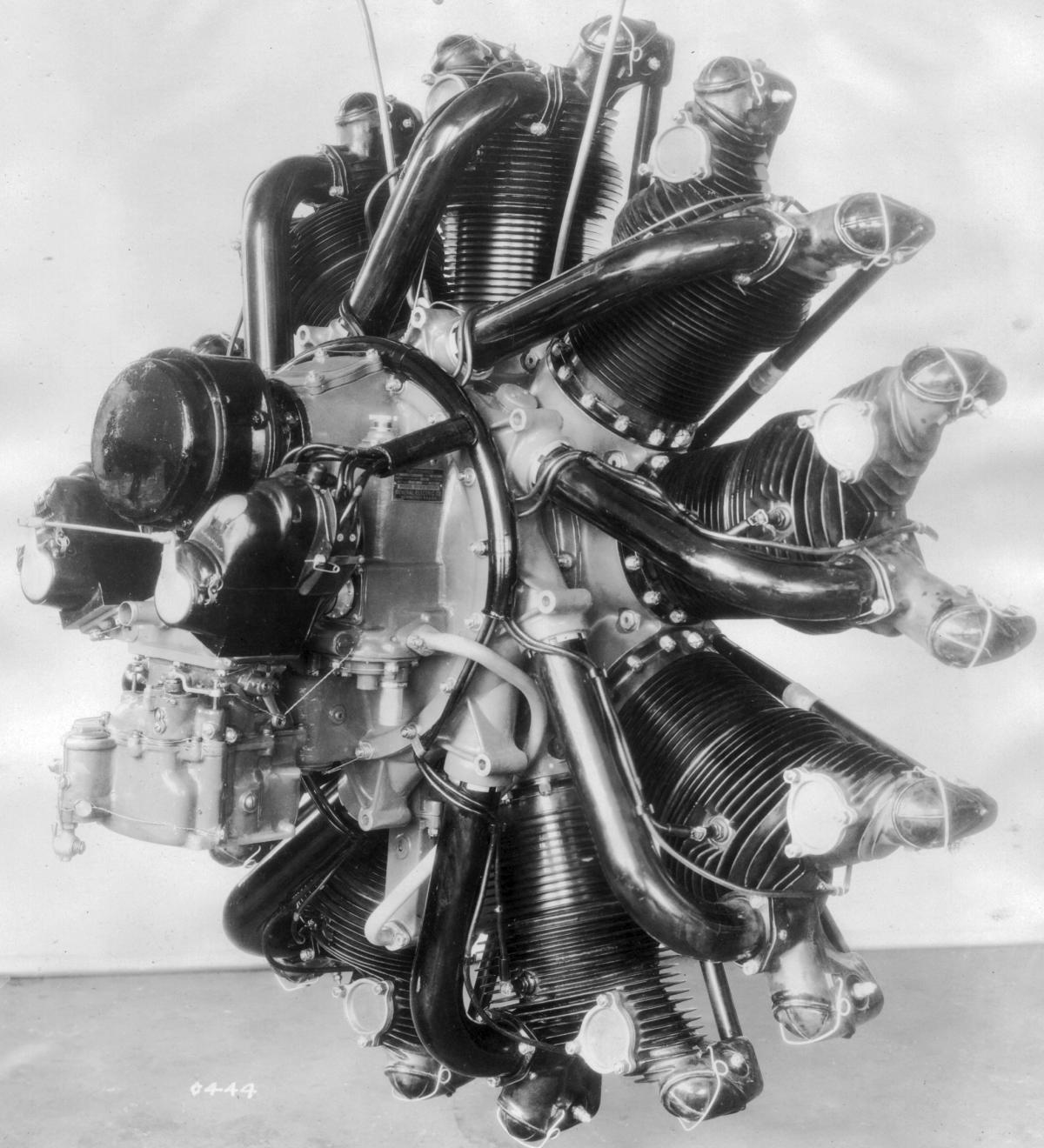
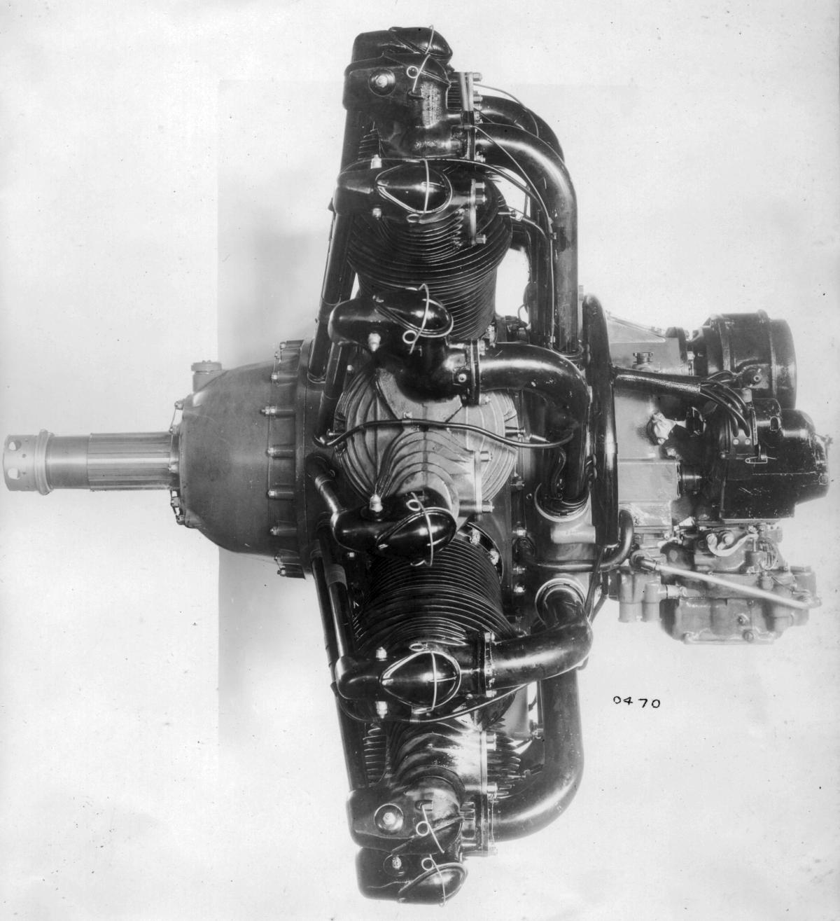
The cylinder barrels have integral fins and are machined from steel forgings. Each barrel is screwed and shrunk into a cast aluminum cylinder head. This is a permanent joint and cannot be disassembled. Each cylinder has one inlet and one exhaust valve, seating on inserts that are shrunk into the head casting. The exhaust valve is sodium cooled. Rocker housings are cast on the cylinder head and the exhaust side has cooling fins.
All valve operating parts are enclosed. The rocker arms are supported by ball bearings in the rocker housings. Eighteen tappets, located in the crankcase front section, actuate the rocker arms through tubular duralumin push rods that have hardened steel ball ends. These rods are enclosed by telescopic covers held in place by springs. The cover tubes can be collapsed by hand, and bayonet locks are provided to retain them in this condition while they are being removed. Each rocker housing has a removable cover held in place by a spring bail. These covers and the push rod covers and push rods can be removed without special tools.
Two concentric valve springs are used. They are secured to the valve stem by a split cone and washer. Inlet and exhaust valve springs are interchangeable. The valve springs can be removed without taking out the rocker arms. After the push rod is taken out, the rocker arm can be tipped up far enough to allow the valve springs to pass. The valve clearance adjusting screw is in the end of the rocker arm over the valve. A half ball is used between the adjusting screw and the valve stem to minimize friction at this point.
The cams, which actuate all valves, run on the crankshaft via a sleeve bearing. A train of spur and internal gears drive the cams at 0.125 times crankshaft speed in the opposite direction to the crankshaft rotation. The cam drive gear on the crankshaft is not keyed to the crankshaft, but to the sleeve on which the cam itself rotates. The front end of this sleeve has a large number of serrations which mesh with similar serrations on the rear end of a sleeve which carries the propeller thrust bearing. These two sets of teeth are normally held tightly together by the thrust bearing nut. When the engine is being timed, however, this nut is slacked off, the two sleeves are slightly separated, and the cam can then be turned by a special wrench which has teeth to engage with one of the cam drive gears. After the adjustment is made, it is locked by screwing up the propeller thrust bearing nut.
Accessories are driven by three lay shafts that extend entirely through the blower and rear sections. Each shaft carries a spur gear at its forward end, which engages with a gear attached to the rear of the crankshaft. The upper shaft provides a drive for the starter and a generator if used. Each of the two lower shafts drives a magneto at its rear end, through a readily adjustable coupling. Two vertical drives are also provided, each driven by a bevel gear. The upper drive is for the gun synchronizer heads and tachometer, while the lower drives an oil pump on the right side and a fuel pump on the left. The supercharger impeller shaft is in line with the crankshaft and driven from it at high speed by two pairs of spur gears.
Lubrication is provided by an oil pump assembly consisting of two gear pumps, one supplying oil under pressure to the engine bearings, and the other for scavenging. Oil is taken from the tank by the pressure pump, and after passing through a strainer located just forward of the carburetor is carried through the blower section, down into the sump and thence up into the hub of the cam drum in the nose of the engine where it is fed into the crankshaft. A relief valve to regulate the oil pressure is located beyond the oil screen just off the strainer chamber. The crankpin hearing, knuckle pins, cam drum, cam drum pinion shaft, accessory shafts, and the supercharger gearing are all lubricated by oil under pressure. Oil is taken from the strainer chamber by drilled passages to lubricate the accessory drives. All the other engine parts are provided for by the mist or spray from the pressure oiled parts except the rocker arms and the magnetos. Early engines had felt reservoirs in each rocker bearing, which were replenished manually; later engines featured pressure lubrication for all valve gear components. All the oil drains into a sump carried between cylinders No. 5 and No. 6, from which it is returned to the oil tank by the scavenging pump. The discharge or warm oil is carried in a jacket around the carburetor elbow to prevent the throttles freezing.
Induction begins when fuel is supplied by a fuel pump to the carburetor. The fuel/air mixture from the carburetor is delivered to the cylinders by means of a centrifugal supercharger, the impeller of which, in normal operation, runs approximately 10,000 rpm. The fuel pump, carburetor, and supercharger are located at the rear of the engine, A mixture control is provided which is effective to 25,000 feet.
Ignition is furnished by two nine-cylinder magnetos located at the rear of the engine, each firing spark plugs in all nine cylinders, thus giving two independent sources of ignition.
 |
 |
 |
 |
| Direct Drive Hornet |
Direct Drive Hornet |
Geared Hornet |
Geared Hornet |
Hornet Approved Type Certificates
ATC
# |
ATC
Date |
Hornet
Model |
Rated
hp |
Rated
rpm |
Alt
(ft) |
Comp
Ratio |
Fuel
Octane |
Prop
Ratio |
SC
Ratio |
Weight
(lb) |
Dia
(in) |
Length
(in) |
Rated
hp/lb |
Remarks |
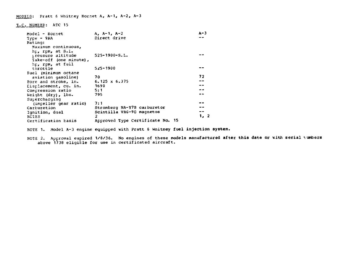
| 15 | 19 Dec 1928 | A, A1 | 525 | 1,900 | 0 | 5.0:1 | 70 | 1:1 | 7:1 | 795 | 55.44 | 44.88 | 0.660 | |
| 15 | | A3 | 525 | 1,900 | 0 | 5.0:1 | 70 | 1:1 | 7:1 | 795 | 55.44 | 44.88 | 0.660 | Fuel Injected, None Mfg |
| 15 | | A2 | 525 | 1,900 | 0 | 5.0:1 | 70 | 1:1 | 7:1 | 795 | 55.44 | 44.75 | 0.660 | |
| 29 | 30 Aug 1929 | A-G, A1-G, A2-G | 500 | 1,900 | 0 | 5.0:1 | 73 | 2:1 | 7:1 | 860 | 55.44 | 51.00 | 0.581 | No A1-G, A2-G Mfg |
| 83 | 27 May 1932 | C | 600 | 2,000 | 0 | 6.0:1 | 80 | 3:2 | 8:1 | 840 | 55.44 | 45.66 | 0.714 | |
| 83 | | TC1 | 600 | 2,000 | 0 | 6.0:1 | 80 | 1:1 | 8:1 | 861 | 55.44 | 45.66 | 0.697 | |
| 92 | 24 Apr 1933 | T1C | 650 | 2,000 | 0 | 6.0:1 | 87 | 1:1 | 10:1 | 870 | 55.44 | 45.66 | 0.747 | |
| 92 | | T1C1 | 675 | 2,000 | 0 | 6.0:1 | 87 | 1:1 | 10:1 | 871 | 55.44 | 45.66 | 0.775 | |
| 92 | | T1D1 | 700 | 2,000 | 0 | 6.0:1 | 87 | 1:1 | 10:1 | 871 | 55.44 | 45.75 | 0.804 | |
| 99 | 25 Apr 1933 | T2C1 | 600 | 2,000 | 0 | 6.0:1 | 80 | 1:1 | 10:1 | 880 | 55.44 | 45.75 | 0.682 | |
| 99 | | T2D1 | 660 | 2,000 | 0 | 6.0:1 | 80 | 1:1 | 10:1 | 880 | 55.44 | 45.75 | 0.750 | |
| 99 | | T2E | 650 | 2,000 | 0 | 6.0:1 | 80 | 1:1 | 10:1 | 975 | 54.69 | 44.23 | 0.667 | |
| 100 | 6 Jun 1933 | S3C1 | 610 | 2,000 | 5,000 | 6.0:1 | 80 | 1:1 | 10:1 | 871 | 55.44 | 45.66 | 0.700 | |
| 100 | | S4D1 | 645 | 2,000 | 3,000 | 6.0:1 | 80 | 1:1 | 10:1 | 891 | 55.44 | 45.66 | 0.724 | |
| 100 | | S4D2 | 645 | 2,000 | 3,000 | 6.0:1 | 80 | 1:1 | 10:1 | 916 | 55.44 | 45.66 | 0.704 | |
| 105 | 12 Aug 1933 | SD-G | 700 | 2,150 | 6,500 | 6.5:1 | 87 | 3:2 | 12:1 | 980 | 55.44 | 50.75 | 0.714 | |
| 106 | 12 Aug 1933 | SD | 675 | 2,050 | 6,000 | 6.5:1 | 87 | 1:1 | 12:1 | 880 | 55.44 | 45.75 | 0.767 | |
| 109 | 30 Oct 1933 | T1D1-G | 700 | 2,150 | 0 | 6.0:1 | 87 | 3:2 | 10:1 | 980 | 55.44 | 50.75 | 0.714 | |
| 114 | 29 Nov 1933 | SD1 | 575 | 2,050 | 2,000 | 5.0:1 | 73 | 1:1 | 8:1 | 891 | 55.44 | 45.66 | 0.645 | |
| 115 | 29 Nov 1933 | SD1-G | 575 | 2,150 | 3,000 | 5.0:1 | 73 | 3:2 | 8:1 | 986 | 55.44 | 50.75 | 0.583 | |
| 116 | 20 Nov 1933 | S1D1 | 525 | 2,000 | 4,000 | 5.0:1 | 73 | 1:1 | 8:1 | 891 | 55.44 | 45.66 | 0.589 | |
| 117 | 29 Nov 1933 | S3D1-G | 670 | 2,150 | 5,000 | 6.0:1 | 80 | 3:2 | 10:1 | 980 | 55.44 | 50.75 | 0.684 | |
| 127 | 9 Jul 1934 | S5D1-G | 700 | 2,150 | 3,500 | 6.0:1 | 87 | 3:2 | 10:1 | 980 | 55.44 | 50.75 | 0.714 | None Mfg |
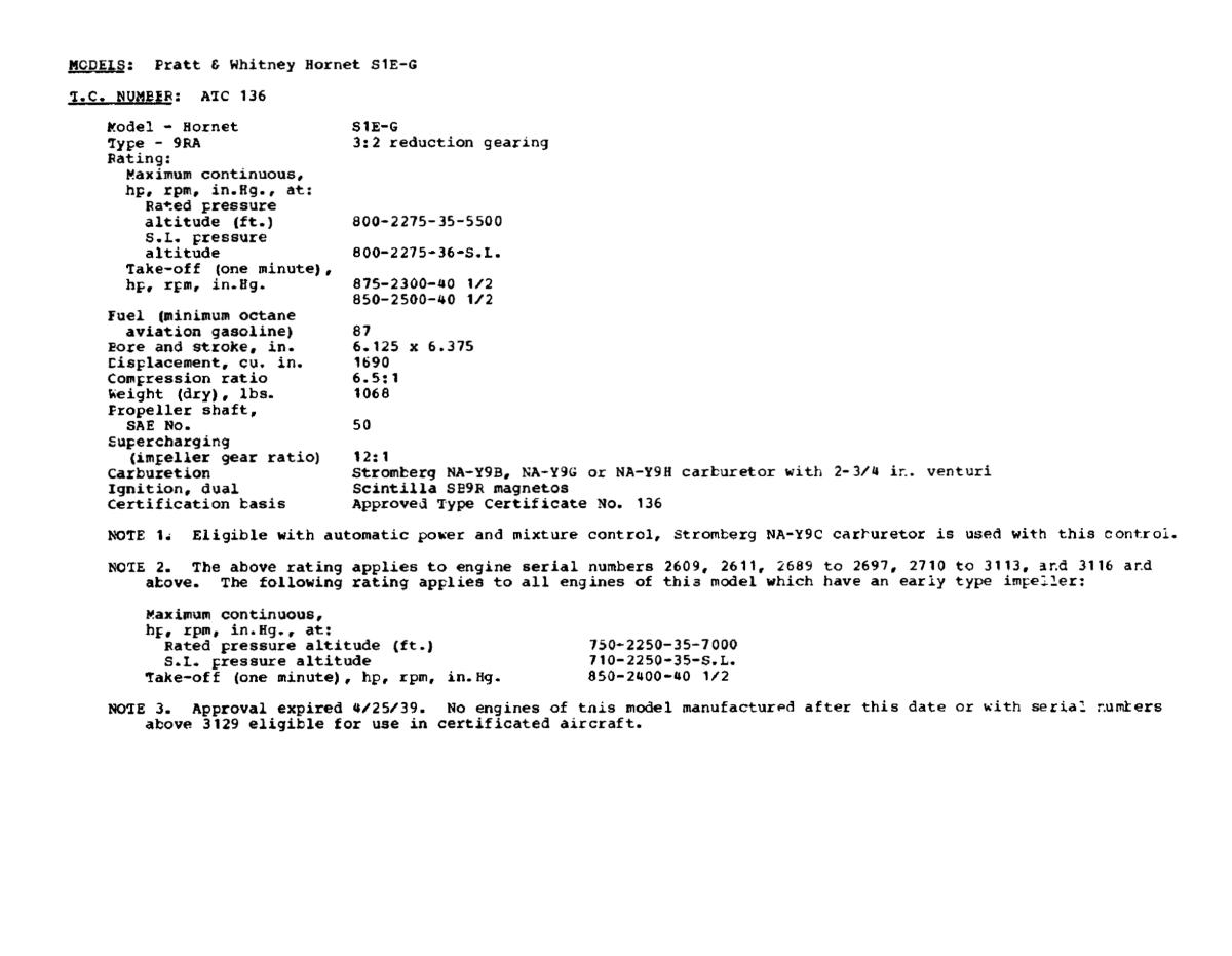
| 136 | 13 Dec 1934 | S1E-G | 800 | 2,275 | 5,500 | 6.5:1 | 87 | 3:2 | 12:1 |
1,068 |
54.44 | 49.38 | 0.749 | |
| 140 | 25 Feb 1935 | S7E-G | 690 | 2,250 | 9,200 | 6.5:1 | 87 | 3:2 | 12:1 |
1,015 |
54.44 | 51.00 | 0.680 | None Mfg |
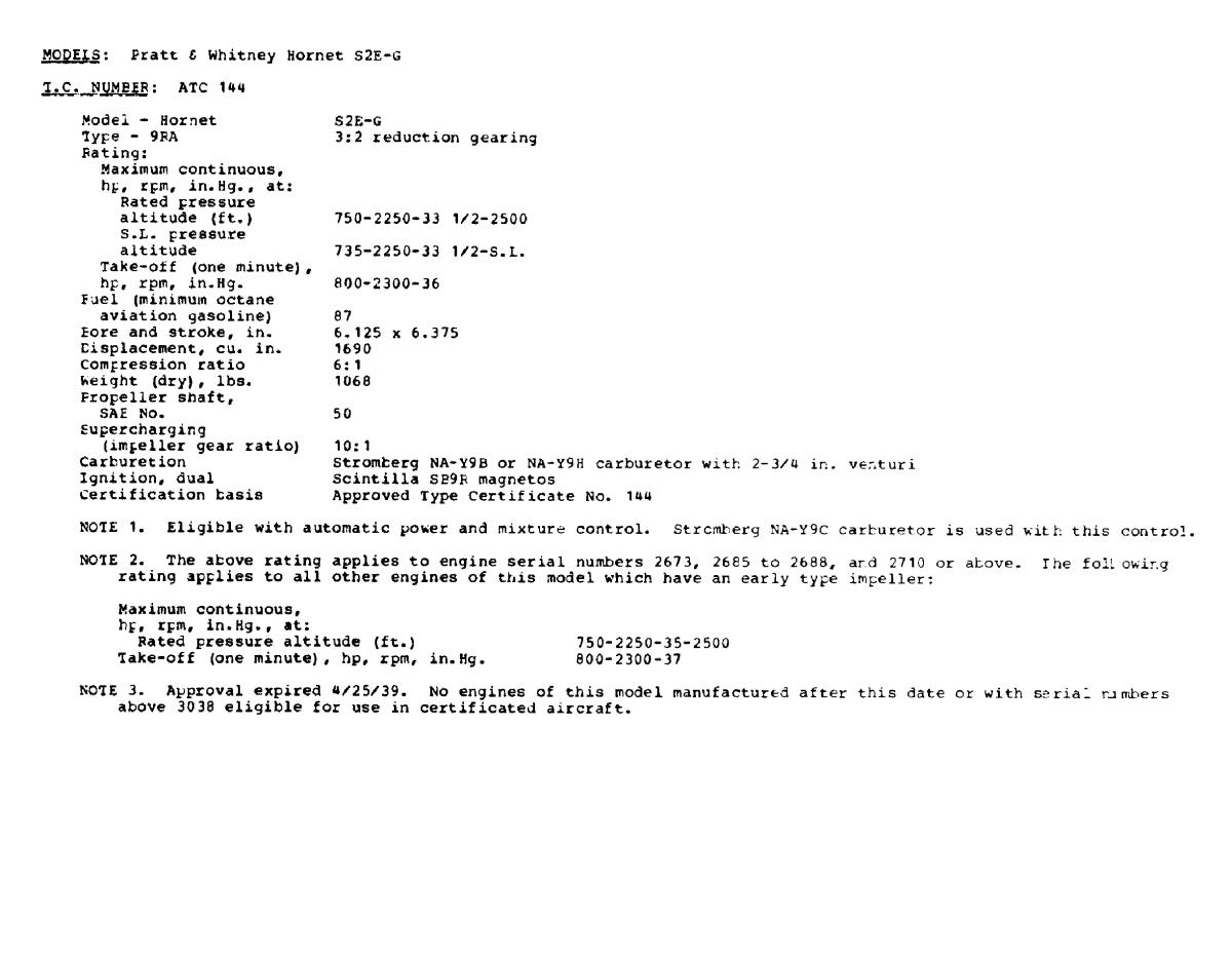
| 144 | 9 Mar 1935 | S2E-G | 750 | 2,250 | 2,500 | 6.0:1 | 87 | 3:2 | 10:1 |
1,068 |
54.44 | 49.38 | 0.702 | |
| 147 | 18 Apr 1935 | S8E-G | 720 | 2,250 | 4,000 | 6.0:1 | 87 | 3:2 | 10:1 |
1,015 |
54.44 | 51.00 | 0.709 | None Mfg |
| 152 | 9 Nov 1935 | S9E | 650 | 2,050 | 3,000 | 6.0:1 | 80 | 1:1 | 10:1 | 920 | 54.44 | 45.38 | 0.707 | |
| 164 | 24 Sep 1936 | S5E | 700 | 2,050 | 6,000 | 6.5:1 | 87 | 1:1 | 12:1 | 975 | 54.69 | 44.23 | 0.718 | |
| 166 | 28 Oct 1936 | S13E-G | 750 | 2,250 | 4,000 | 6.5:1 | 87 | 3:2 | 10:1 |
1,068 |
54.44 | 49.38 | 0.702 | |
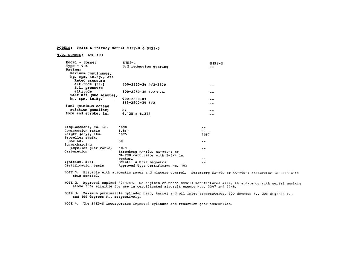
| 193 | 24 Feb 1938 | S1E2-G | 800 | 2,250 | 5,500 | 6.5:1 | 87 | 3:2 | 10:1 |
1,075 |
54.44 | 49.67 | 0.744 | |
| 193 | | S1E3-G | 800 | 2,250 | 5,500 | 6.5:1 | 87 | 3:2 | 10:1 |
1,087 |
54.69 | 50.52 | 0.736 | |
| The Competion: Wright Cyclone R-1750 |
| 17 | 26 Jan 1929 | Wright R-1750-E | 525 | 1,900 | 0 | 5.1:1 | 73 | 1:1 | 8.74:1 | 835 | 54.69 | 43.84 | 0.629 | |

