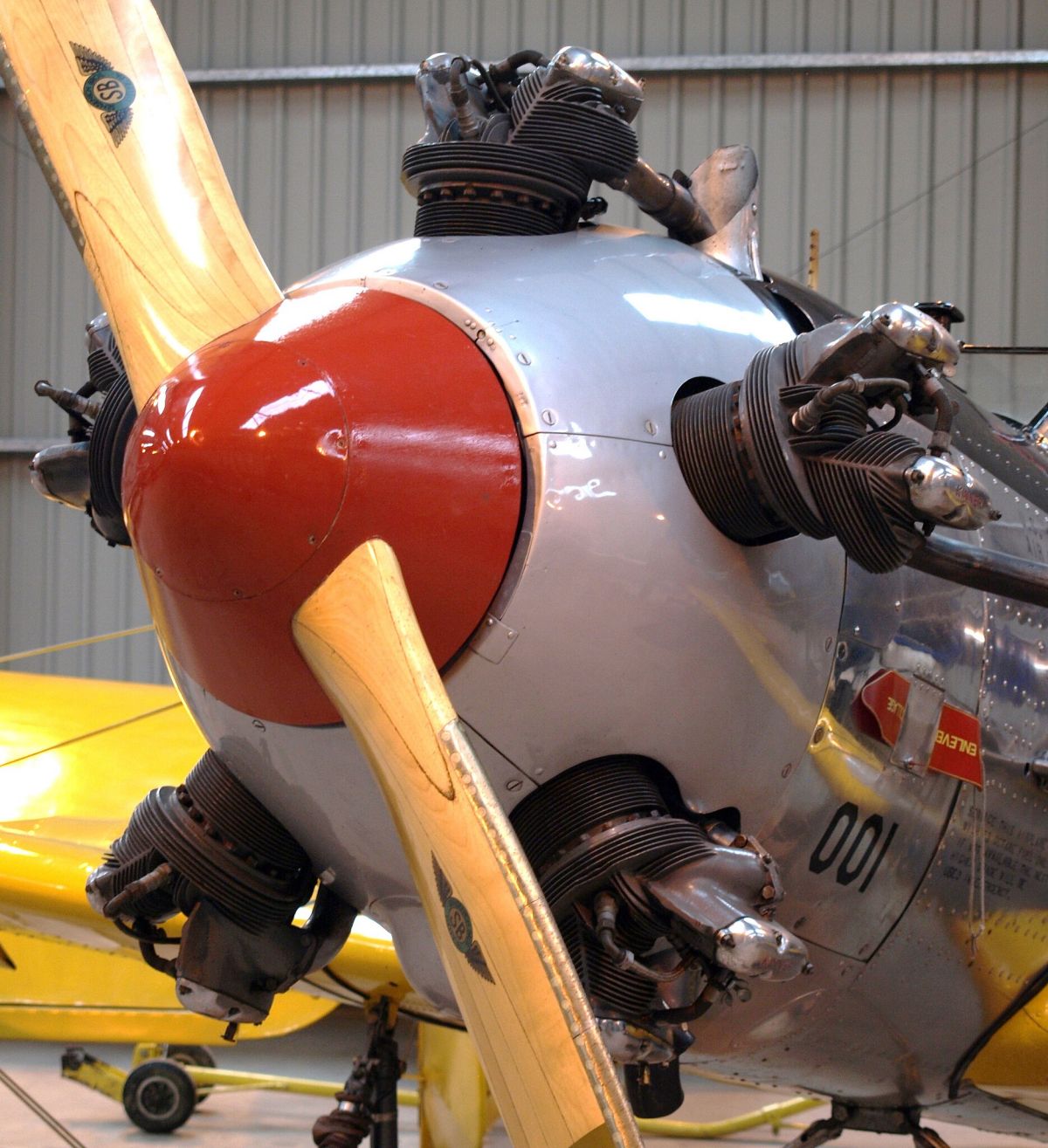
Kinner R-56 on a Ryan PT-22 Recruit
(aka "Cadet Eliminator" because of its nasty
stall/spin characteristics), Shuttleworth Collection
Kinner Aircraft Engines
Compiled by Kimble D. McCutcheon
Published 1 Jan 2024
Kinner R-56 on a Ryan PT-22 Recruit (aka "Cadet Eliminator" because of its nasty stall/spin characteristics), Shuttleworth Collection |
Winfield Bertrum "Bert" Kinner (16 Dec 1882 – 4 Jul 1957) was a colorful West-coast aircraft and engine designer [Koontz, Part 1, Part 2] responsible for the first folding wing airplane and the Kinner aircraft engine line. Burt Kinner founded Kinner Motors, Inc., which became the Kinner Airplane & Motor Corporation of Glendale, California, producer of aircraft and radial engines. Kinner began experimenting with aircraft shortly after arriving in California, and in 1920, designed and built the Airster, a single-engine biplane. This Airster was followed by a series of sport monoplane singles designed by Max. B Harlow and built by Kinner: the Sportster (1932), the Sportwing (1933), the Playboy (1933) and the Envoy (1934).[Wiki] |
Starting in 1921, Kinner experimented with the K-1, a three-cylinder air-cooled radial that which was very much like the three-cylinder Lawrance designs. Many of this engine's structural details were incorporated in the five-cylinder K-2 engine that followed.
 |
 |
 |
 |
 |
 |
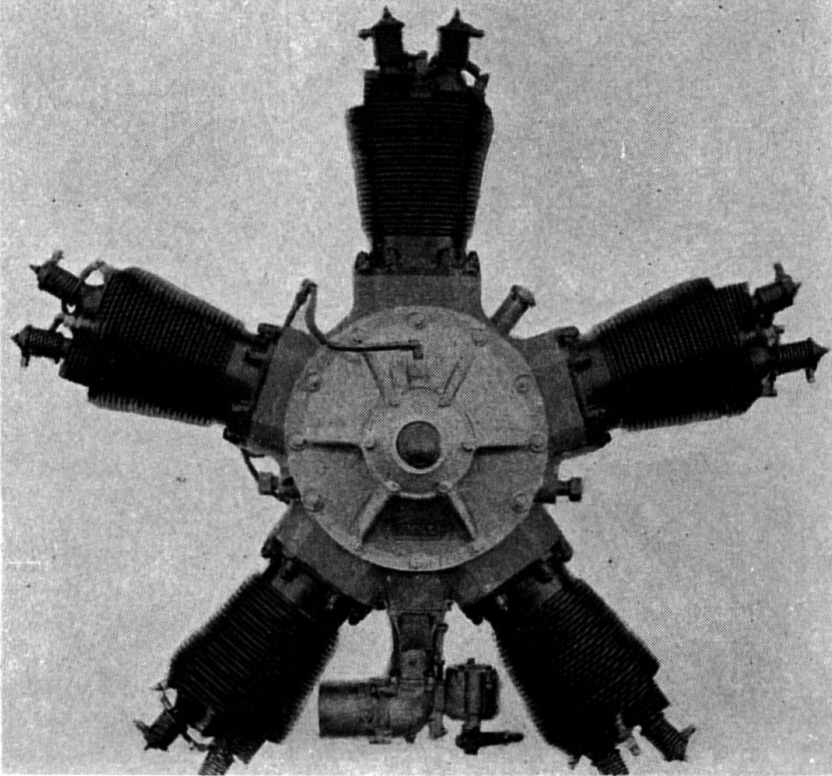
| Kinner K-2 | Kinner K-3 | ||||
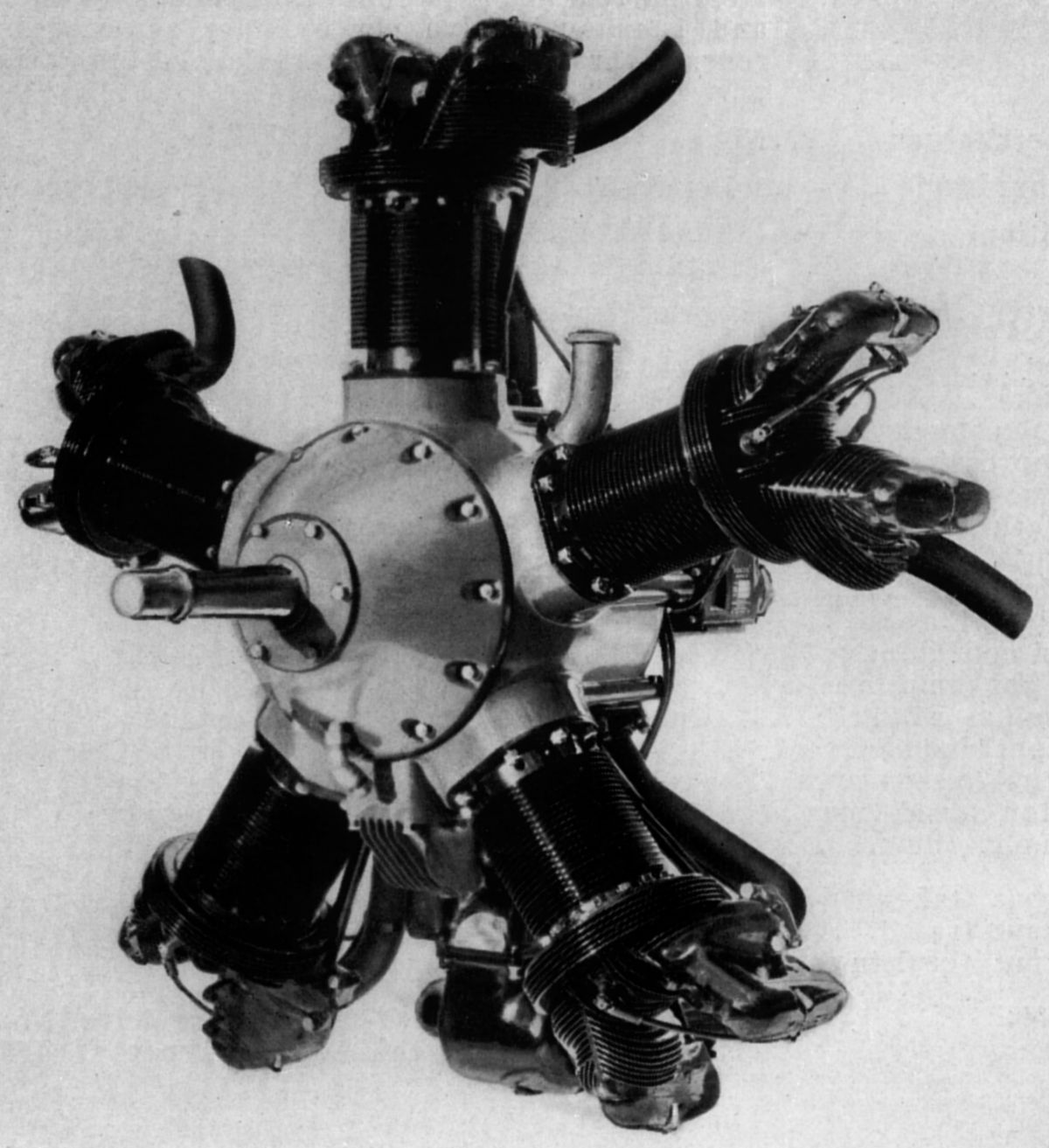
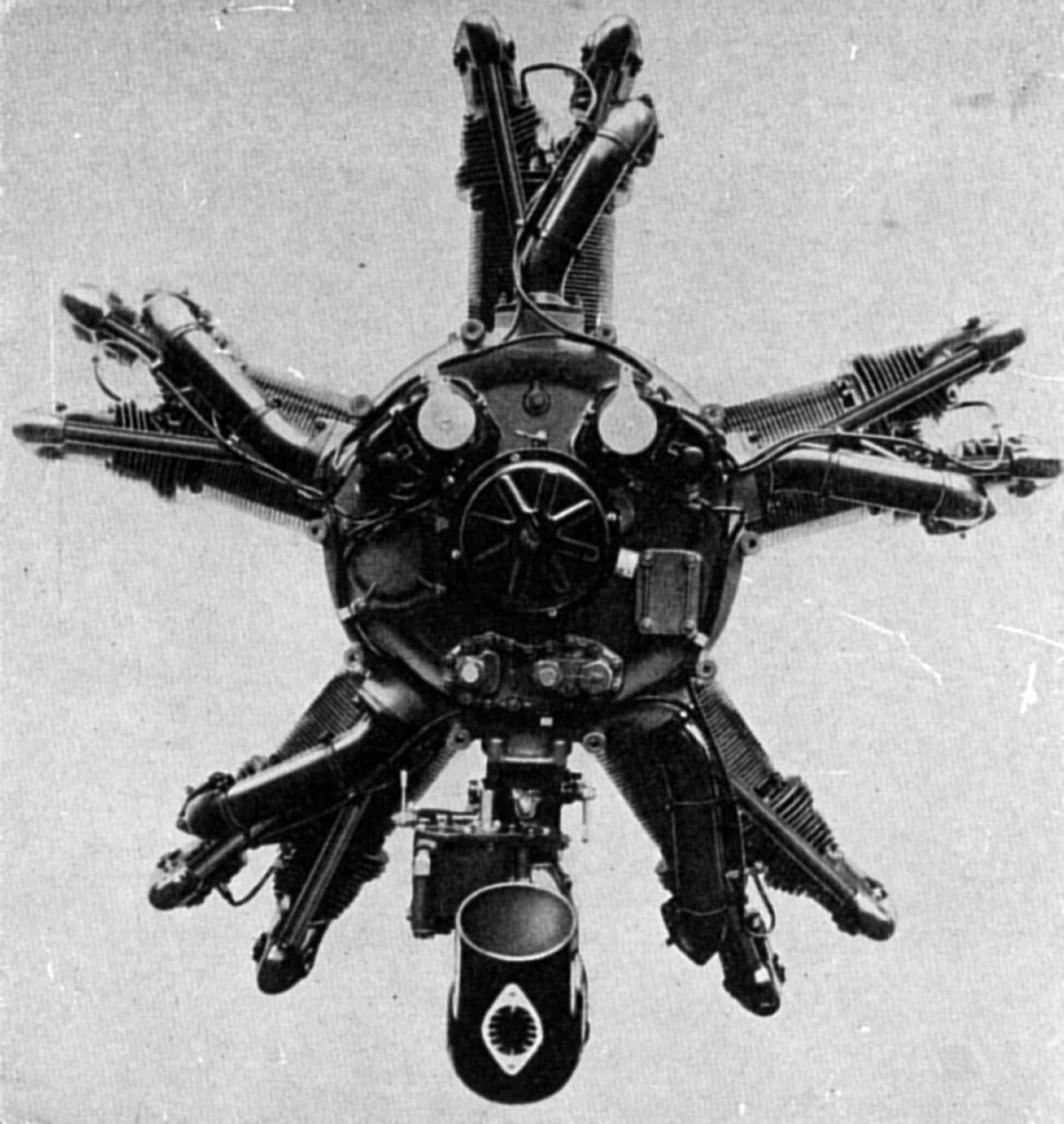
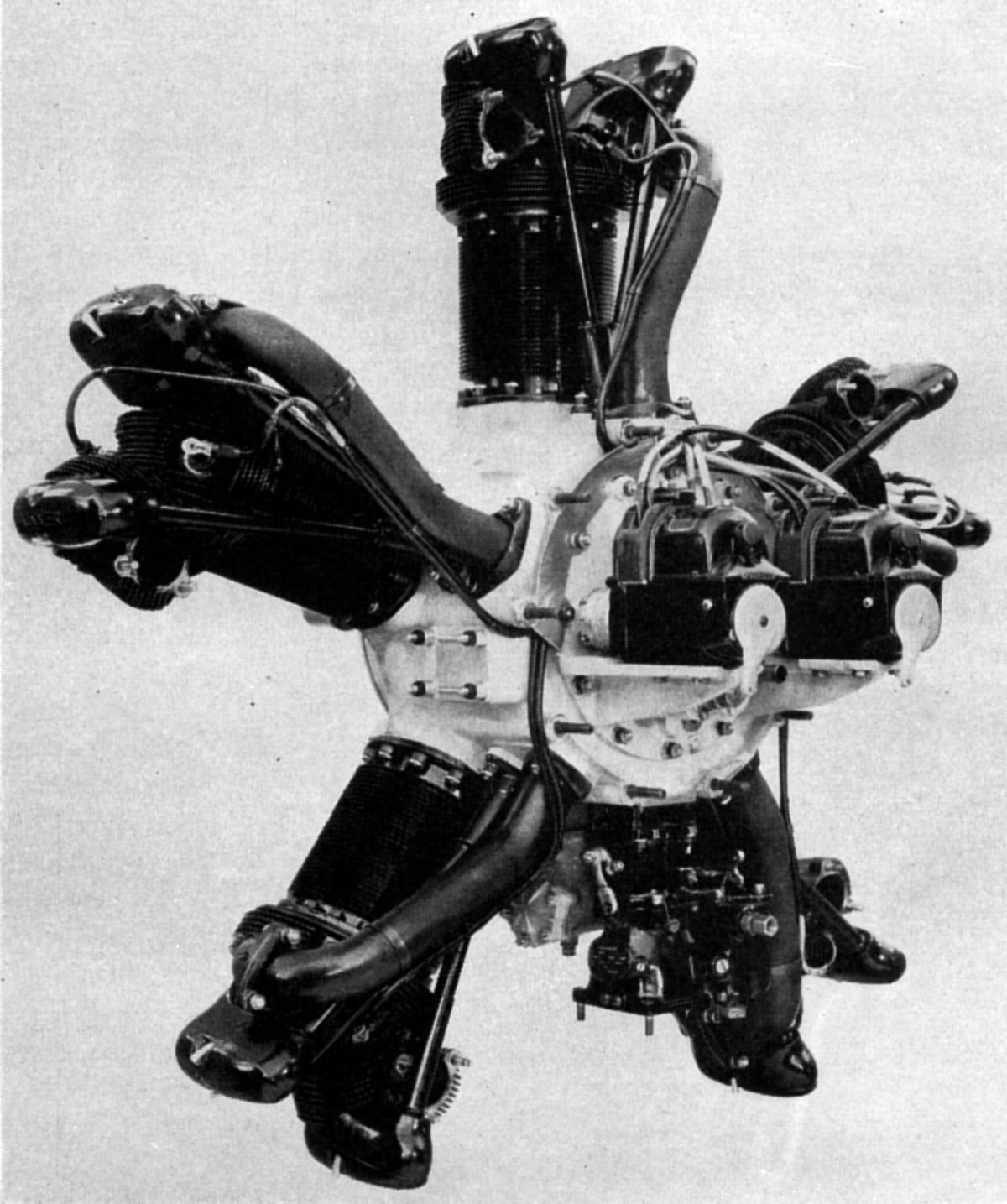
The 1927 Kinner K-2 was a five-cylinder air-cooled radial with a 4.25" (107.95 mm) bore, 5.25" (133.35 mm) stroke, 372.39 in³ (6.102 l) displacement and 5.0:1 compression ratio weighing 231 lb (105 kg). It was rated 100 hp at 1,800 rpm. Its cast aluminum alloy cylinders had integral cooling fins and cast-in-place bronze valve seats. A steel liner was shrunk into the cylinder and held in place by a flange machined on the skirt. Two slightly inclined overhead valves were operated by push rods and rocker arms carried on steel supports screwed into cylinder head bosses. Aluminum alloy pistons were fitted with three compression rings and two oil-scraper rings, one above and the other below the piston pin. Articulated connecting rods were attached to a split master rod fitted with a white-metal-lined bronze-backed bearing. The single-throw crankshaft was fitted with attachable counterweights, and two white-metal-lined bronze-backed bearings were used on its main journals. A ball thrust bearing carried the propeller thrust load. The aluminum alloy crankcase was closed at the front by a cover or nose piece, and at the rear by an accessory case. The rear crankcase wall supported five camshafts, each having an inlet and exhaust cam with a roller follower for its respective cylinder. These camshafts were driven from the crankshaft by spur gears at one-half engine speed.. A cast aluminum intake manifold, to which the carburetor was attached, was fastened to the crankcase rear by ten cap screws. Separate pipes with a flange joint at each cylinder were connected to the manifold by rubber hoses and clamps. The mixture was furnished by a Zenith carburetor. Dry-sump lubrication used a gear scavenge pump and a gear pressure pump that delivered oil to the hollow crankshaft at about 30 psi. The K-2 engine used a Philbrin ignition system in conjunction with dry cells.
The Kinner K-3 added a gear box at the rear for mounting two Scintilla magnetos.
. |
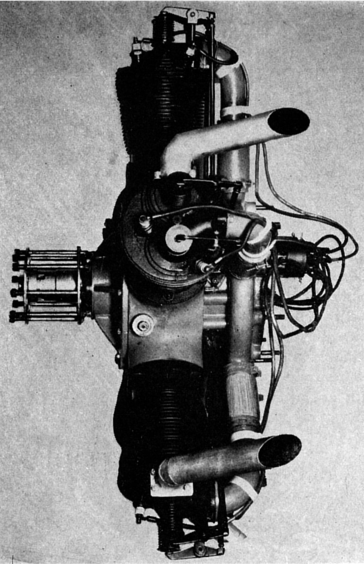
| Kinner K-5 |
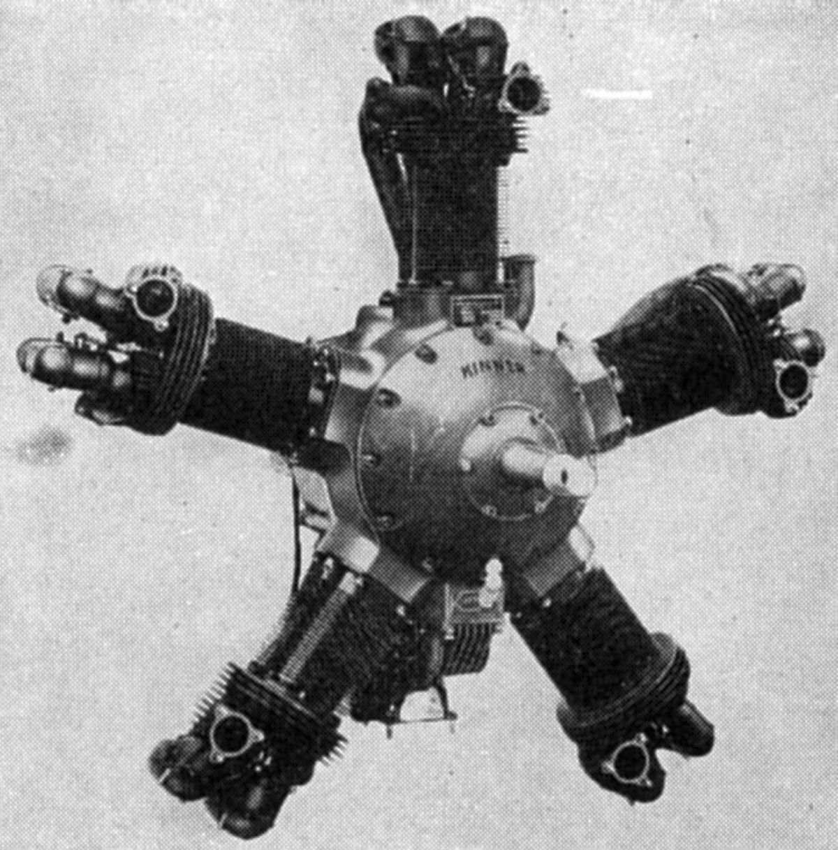
The K-5, a further evolution of the K-3, was issued Approved Type Certificate No. 3 by the Department of Commerce on 18 Jun 1928, rated 75 hp at 1,810 rpm. A rating change to 90 hp followed, and on 29 Apr 1930, a rating of 100 hp at 1,810 rpm was approved. The engine submitted for type test incorporated several improvements over the original K-2, including an annular manifold cored integral with the crankcase, with individual pipes to each cylinder connected to the manifold by hoses and clamps.
Early in 1929, Kinner started using a completely redesigned cylinder, which the Department of Commerce approved without test. The new cylinder barrels, with integral cooling fins, were machined from steel forgings. The cylinder head was an aluminum-alloy casting with bronze valve seats shrunk and rolled into place. The head and barrel were bolted together. The overhead valves were operated by means of rocker arms carried on supports cast integral with the cylinder head. The rocker arm and valve spring were enclosed by a pressed steel cap. Stromberg carburetors were now used, and provision was made for mounting a Heywood compressed-air starter.
 |
| K-5 Series 2 |
About the same time the above improvements were put into effect, the engine became known as the K-5 Series 2. It was equipped with rear-exhaust cylinder heads featuring longer fins spaced closer together, and had about three times as much cooling fin area as the front-exhaust head. Increased angle between valves resulted in a stronger head and provided additional metal between valve seats. Cylinder heads included cowling ring support lugs. Other improvements followed, important among these being an increase in the number of bolts used in joining the cylinder head and barrel. The front cover or nose piece was re-designed, the new part having a smooth convex outer surface, which increased the strength and improved the appearance. Pistons were now fitted with three compression rings and one oil scraper ring located above the piston pin. The carburetor was provided with an air heater, and the oil pressure ranged from 80 to 90 psi.
 |
 |
| Kinner K-5B | |
A later Kinner K-5B engine was given a maximum rating only by the manufacturer of 105 hp at 1,900 rpm The dry weight of this engine, without starter, was 275 lb (125 kg) These engines were supplied with either Stromberg NAR-5A or Holley No. 419 carburetors. The guaranteed fuel and oil consumptions were 0.55 and 0.010 lb/hp/hr. Diameter was 45.75" (1,162 mm) and the length, without starter, was 32.25" (819 mm). In most other respects, this engine was similar with the earlier models.
 |
| Kinner B-5 |
The Kinner Model B-5, conforming to Approved Type Certificate No. 51 (31 May 1930), was rated 125 hp at 1,925 rpm. With a 4.625" (117.48 mm) bore, 5.250" (133.35 mm) bore, 441.00 in³ (7.237 l) and 5.25:1 compression ratio, it weighed 295 lb (88 kg) minus carburetor air heater, exhaust collector ring, starter, and propeller hub. The hub for a wooden propeller weighed 8.5 lb (3.86 kg), and individual exhaust stack weight, with air heater and exhaust control valve, did not exceed 30 lb. The engine could be fitted with forward exhaust collector ring, including stacks, carburetor intake, and hot and cold air-valve, with a weight increase that did not exceed 30 lb. The B-5 fitted the same 14"-diameter bolt circle used to mount the K-5. B-5 diameter was 45.375" (1,152 mm) and length was 32.313" (821 mm). The B-5 was supplied with the rear-exhaust cylinder heads and a SAE No. 1 tapered propeller shaft as standard equipment. The B-54 had an SAE 10-spline propeller shaft. Military models R-440-1 and R-440-3 were essentially equivalent to the B-5 and B-54.
 |
| Kinner C-5 |
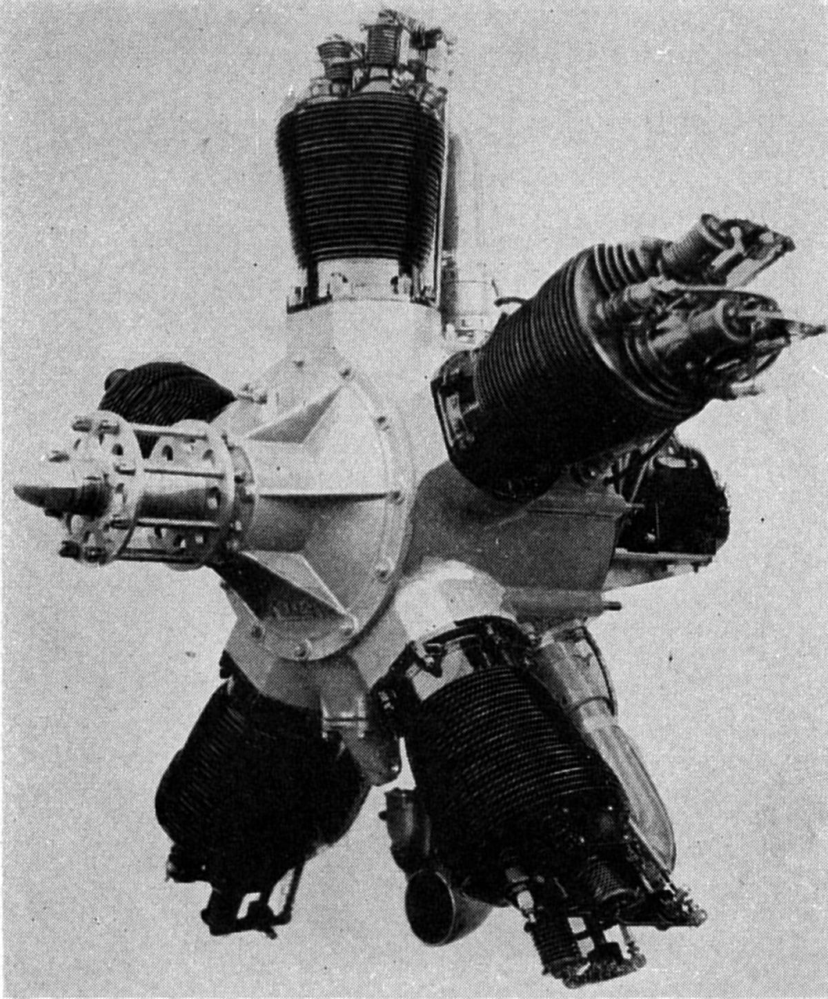
The Kinner Model C-5, first exhibited at the St. Louis Aircraft Show in February 1930, closely followed the K-5 and B-5 designs, but was much larger. With a 5.625" (142.875 mm) bore, 5.750" (146.050 mm) stroke, 714.45 in³ (11.708 l) displacement and 5.25:1 compression ratio, its approved rating was 210 hp at 1,900 rpm as per Department of Commerce Approved Type Certificate No. 62, issued 6 Oct 1930. Cruising specific fuel and oil consumptions were 0.50 and 0.015 lb/hp/hr. The guaranteed full-throttle (1,900 rpm) sfc was less than 0.60 lb/hp/hr. Diameter was 50" (1,270 mm), length without starter was 34.8125", mounting bolt circle diameter was 19.25" (489 mm), and weight, less propeller hub, carburetor air-heater, exhaust collector ring, starter, generator, or fuel pump, was 420 lb (190 kg). The optional nose-type exhaust collector weighed about 40 lb (18 kg). Dual ignition was furnished by two Scintilla PN5-DF magnetos, flange mounted on the engine rear. The mixture was supplied by a Stromberg NA-R7 carburetor, and the fuel pump was a type C-5, developed by the Army Air Corps. Provision was made for mounting standard types of starters and generators.
 |
 |
| Kinner R-5 |
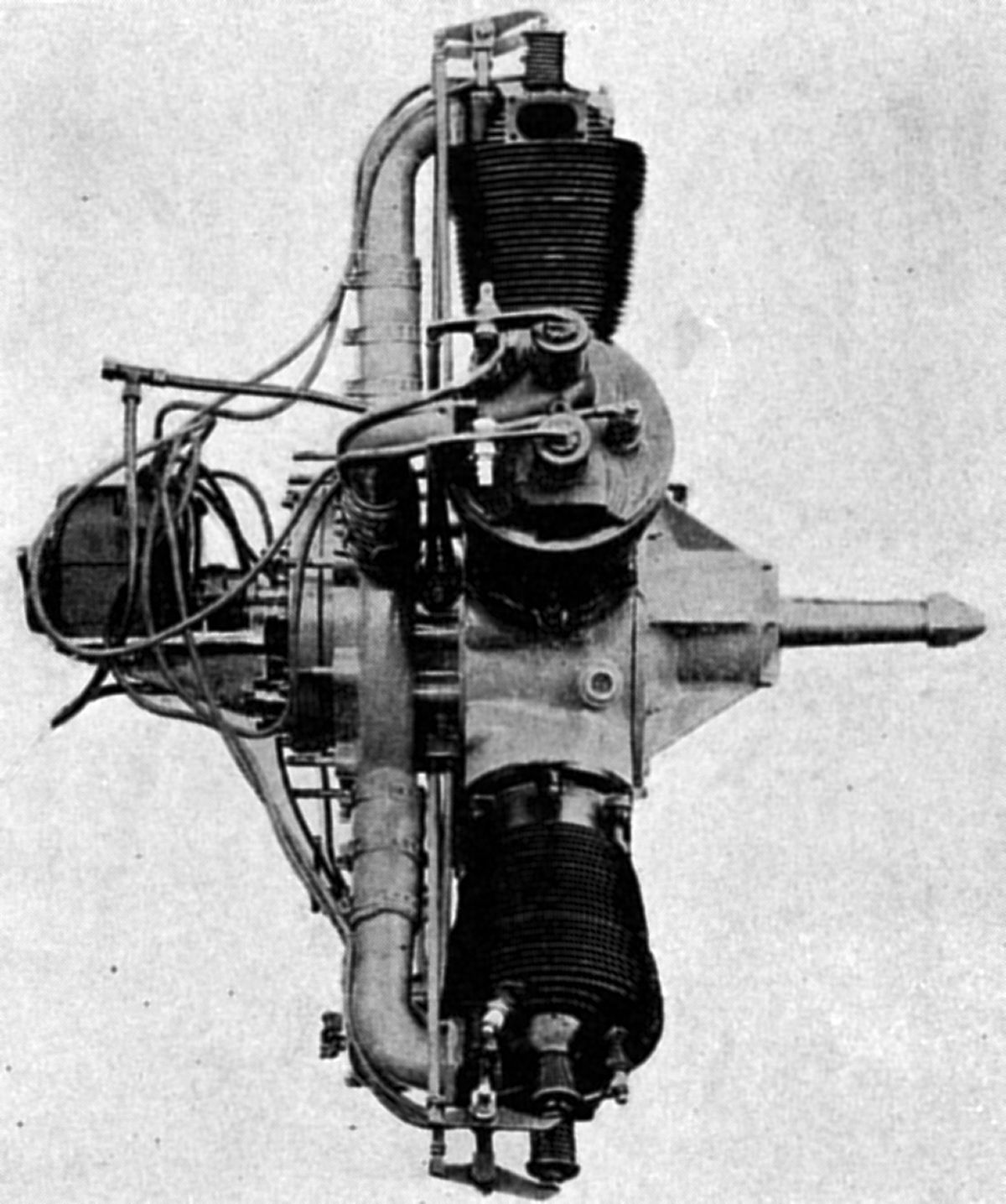
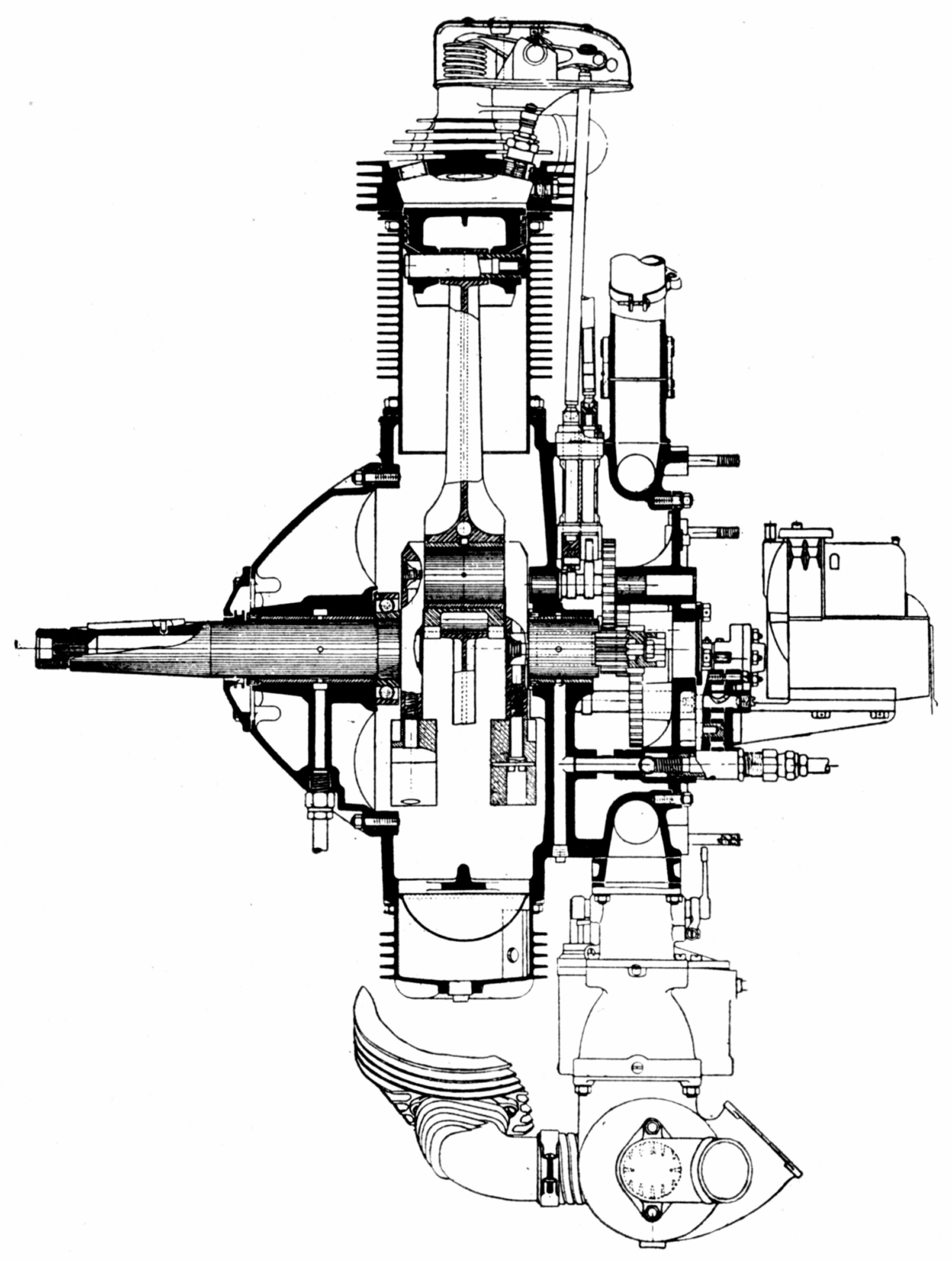
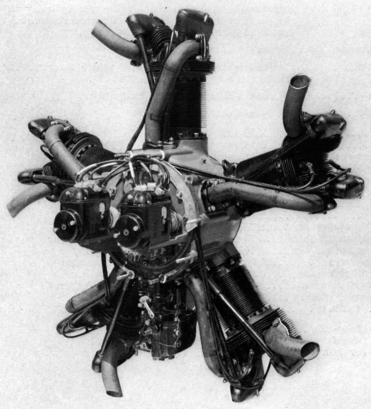
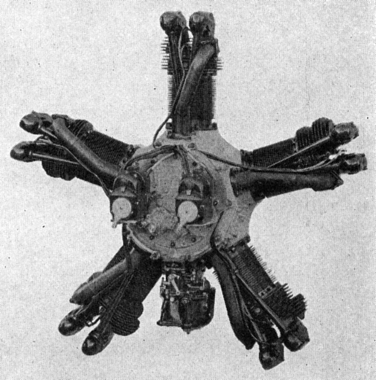
The Kinner R-5, another air-cooled radial five, was an improved and enlarged B-5 rated 160 hp at 1,975 rpm. Department of Commerce Approved Type Certificate No. 77 was issued on 21 Jan 1932. With a 4.875" (123.825 mm) bore, 5.25" (133.35 mm) stroke, 489.97 in³ (8.029 l) displacement and 5.1:1 compression ratio, the engine weighed 325 lb (147 kg). Fuel pump and generator drives added 9 lb (4.1 kg); the forward exhaust collector ring, which included an air-heated valve, added an additional 24 lb (11 kg) The mounting bolt circle diameter was 14" (356 mm), overall diameter was 45.75" (1,162 mm) and the length 32.3125" (821 mm). The R-5 included the nose exhaust collector ring as standard equipment, while a hub suitable for wooden propeller and the fuel pump and generator drive were optional. Provision was made for mounting an Eclipse electric starter and generator, or a Heywood air starter. Two machine gun synchronizing drives could be special-ordered.
The removable aluminum alloy cylinder heads were secured to the forged-steel cylinder barrels by sixteen studs each. Two slightly inclined overhead valves in each cylinder head were actuated by fully enclosed push rods and rocker arms. Each aluminum alloy piston was fitted with three compression rings and one oil scraper ring, all located above the full-floating piston pin. The articulated connecting rods were machined from chrome-molybdenum-steel forgings and polished all over. The single-throw counterbalanced crankshaft also machined from an SAE 4130 steel forging. It was carried on two plain copper-lead bearings and provided with a ball bearing to carry propeller thrust loads. The cast aluminum-alloy crankcase was composed of three sections. The main section carried the cylinder mounting pads, generator, fuel pump, induction manifold and supported the rear main bearing and the cam and accessory drive shaft front bearings The front section carried the front main bearing support, and the rear section carried the oil pump, magnetos, cam and accessory drive shaft rear bearings, and a standard SAE starter adapter.
The R-5 engine adhered to many design features established by earlier Kinner engines. A separate camshaft was employed for each of the five cylinders, with each shaft being driven at one-half crankshaft speed through a spur gear meshing with a pinion on the crankshaft rear. The magnetos were driven by spur gears meshing with the cam gears, and the gear-type oil pressure and scavenging pumps were driven by shafts keyed into slots in the ends of numbers three and four camshafts. All oil passages in the R-5 model were contained within the crankcase. Oil pressure of 90 – 100 psi was maintained at the bearings. Dual ignition was furnished by two Scintilla magnetos, and the mixture was provided by a Stromberg carburetor. Standard equipment included rear-exhaust cylinder heads and lugs for cowling ring support.
 |
 |
|
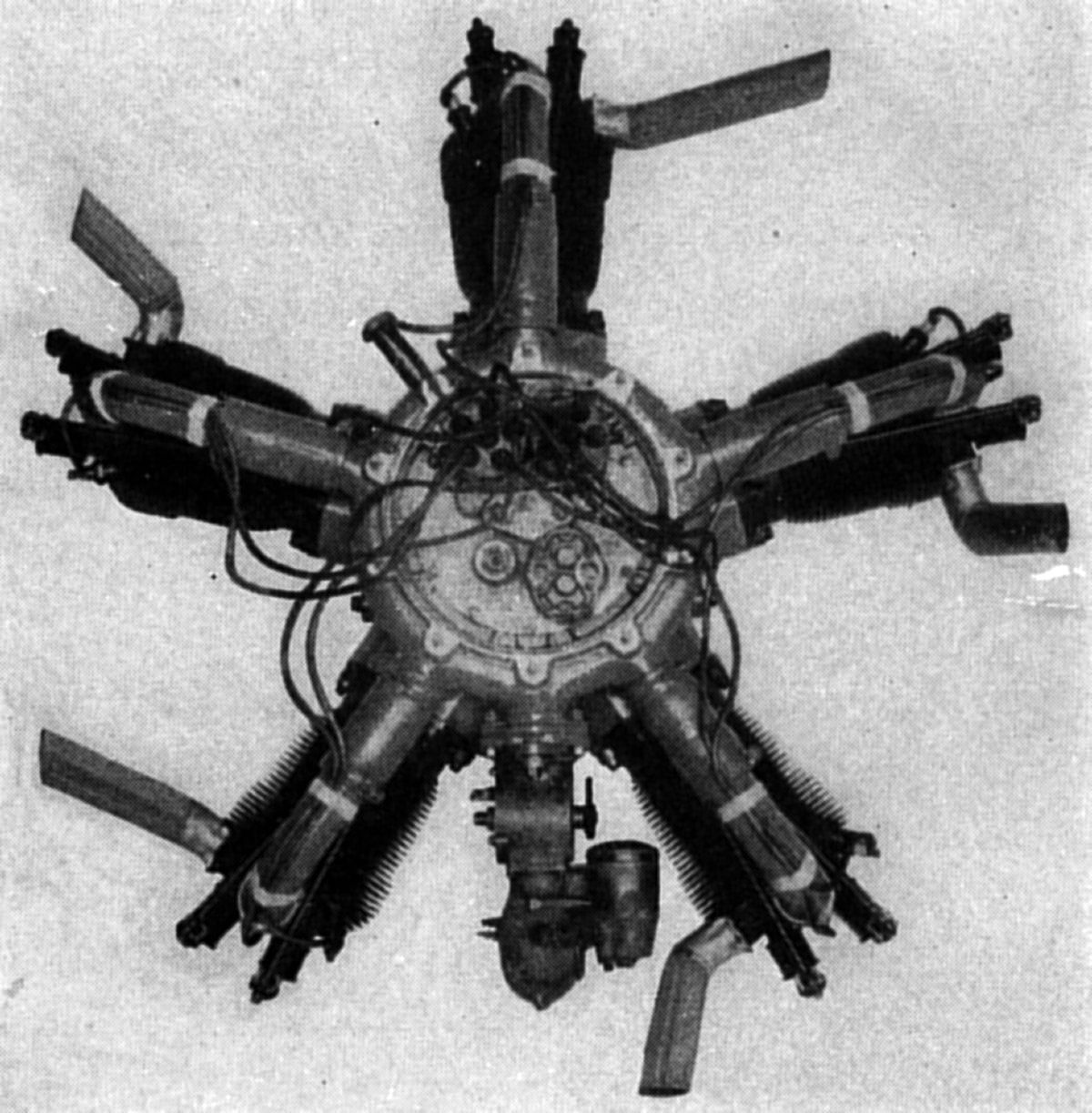
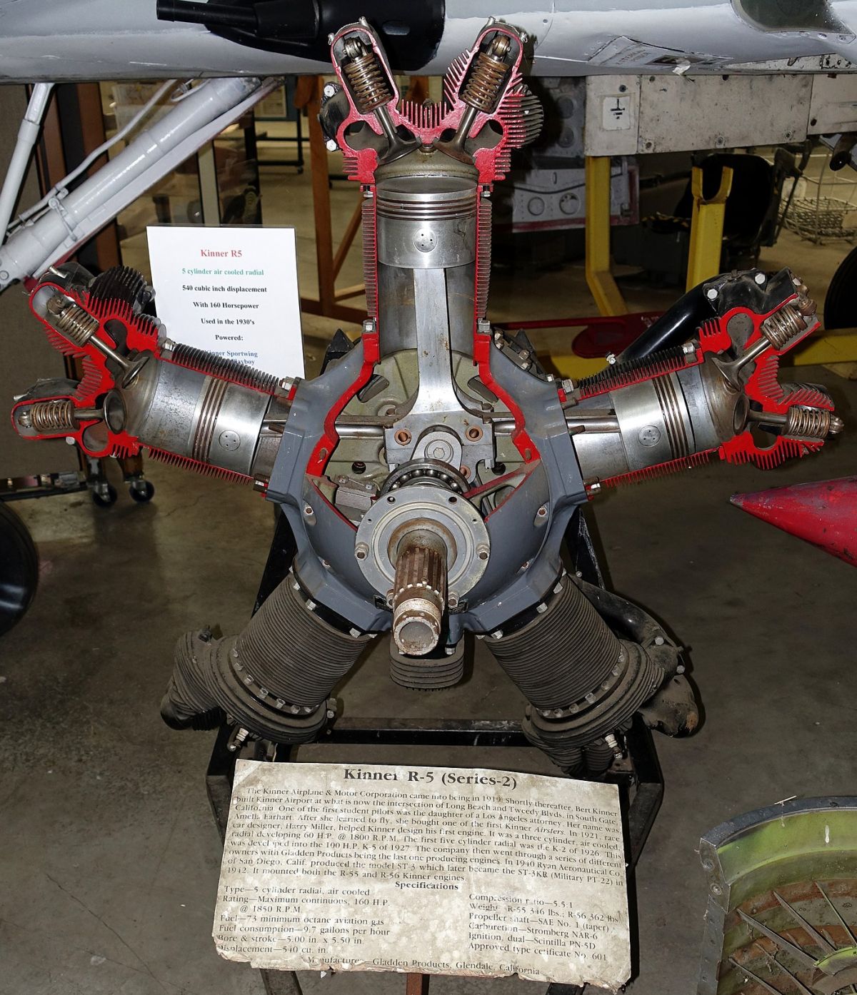
| R-5 Series 2 (Wikimedia, Aero39) | ||
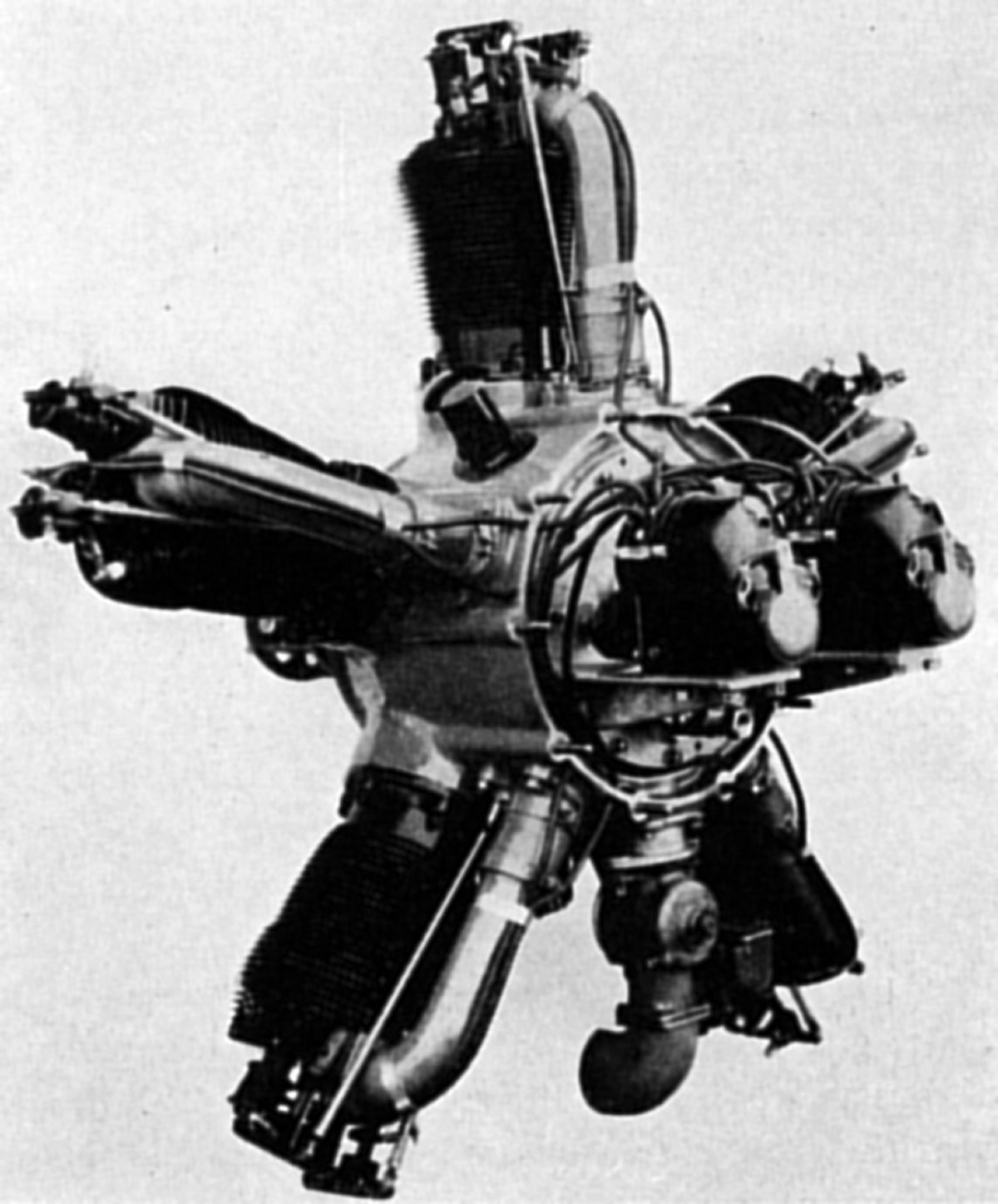
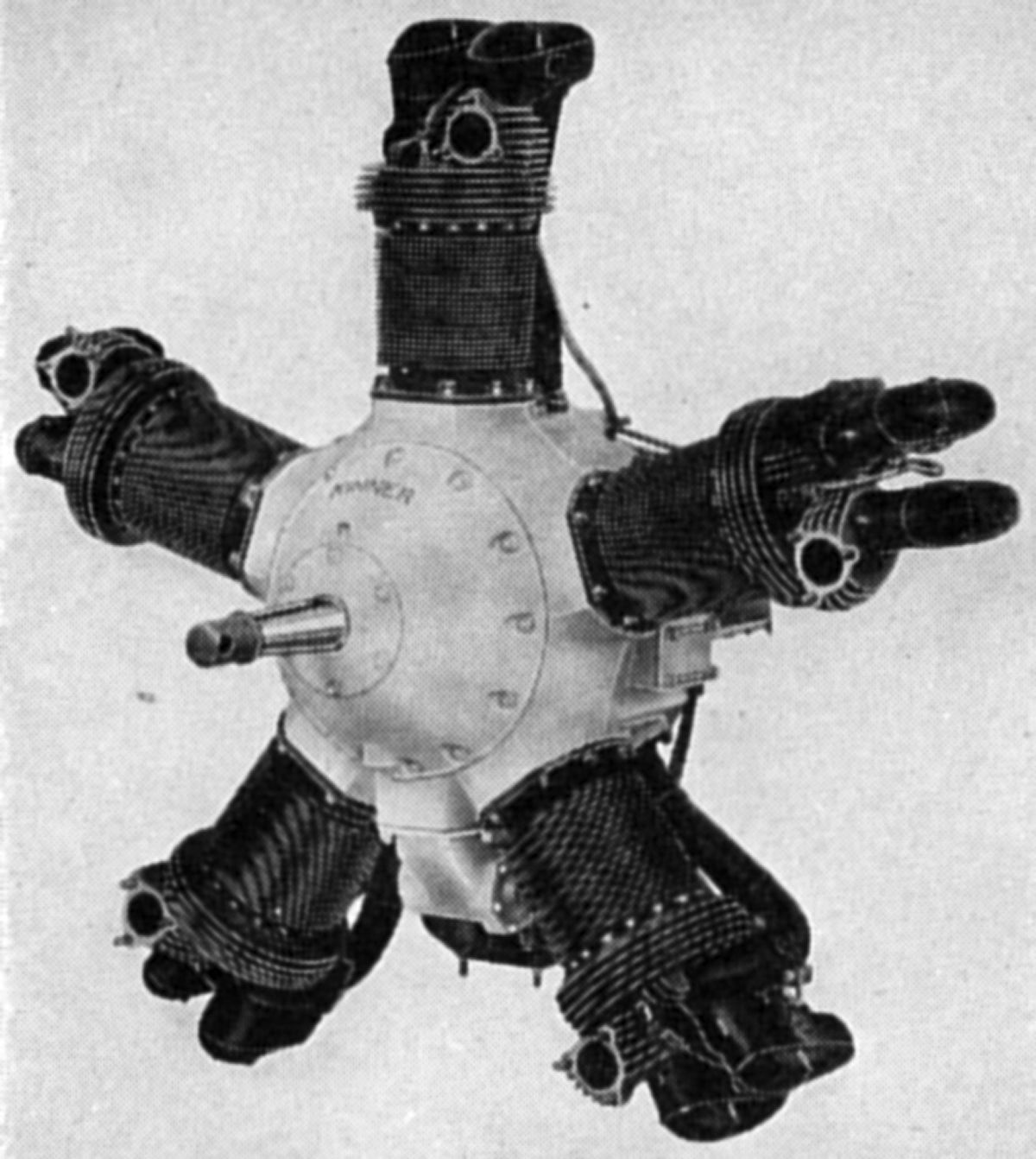
The Kinner R-5 Series 2 (also R-55 and R-56, civilian equivalents to military R-540-1 and R-540-2 engines) were awarded Department of Commerce Approved Type Certificate No. 153 on 18 Dec 1935. With a 5.000" (127.000 mm) bore, 5.500" (138.700 mm) stroke, 539.96 in³ (8.848 l) displacement and 5.5:1 compression ratio, it was rated 160 hp at 1,850 rpm using 73 octane fuel. Weights varied depending on model; see Type Certificate 153 for the details. The rear exhaust collector ring, including air heater valve, weighed 17 lb (7.71 kg).
Compared to earlier Kinner engines, the R-5 Series 2 featured greatly increased cooling area resulting from longer and more closely spaced fins on the aluminum-alloy cylinder heads. The valves were separated by a greater included angle, resulting in more metal between the valve seats. The exhaust ports faced aft, as did correspondingly-enlarged inlet ports. The crankshaft size was increased to provide greater strength, and both main and crankpin bearings were steel-backed copper-lead. The master connecting rod was enlarged and strengthened, and all oil passages were contained within the engine. Needle bearings supported the valve-end rocker arm rollers ; the main rocker arm roller bearing was lubricated through high-pressure grease connections. Aside from some other minor improvements, the design closely followed previous Kinner engines.
 |
 |
| Kinner C-7 SC/BSC-7 | |
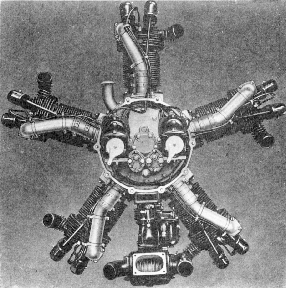
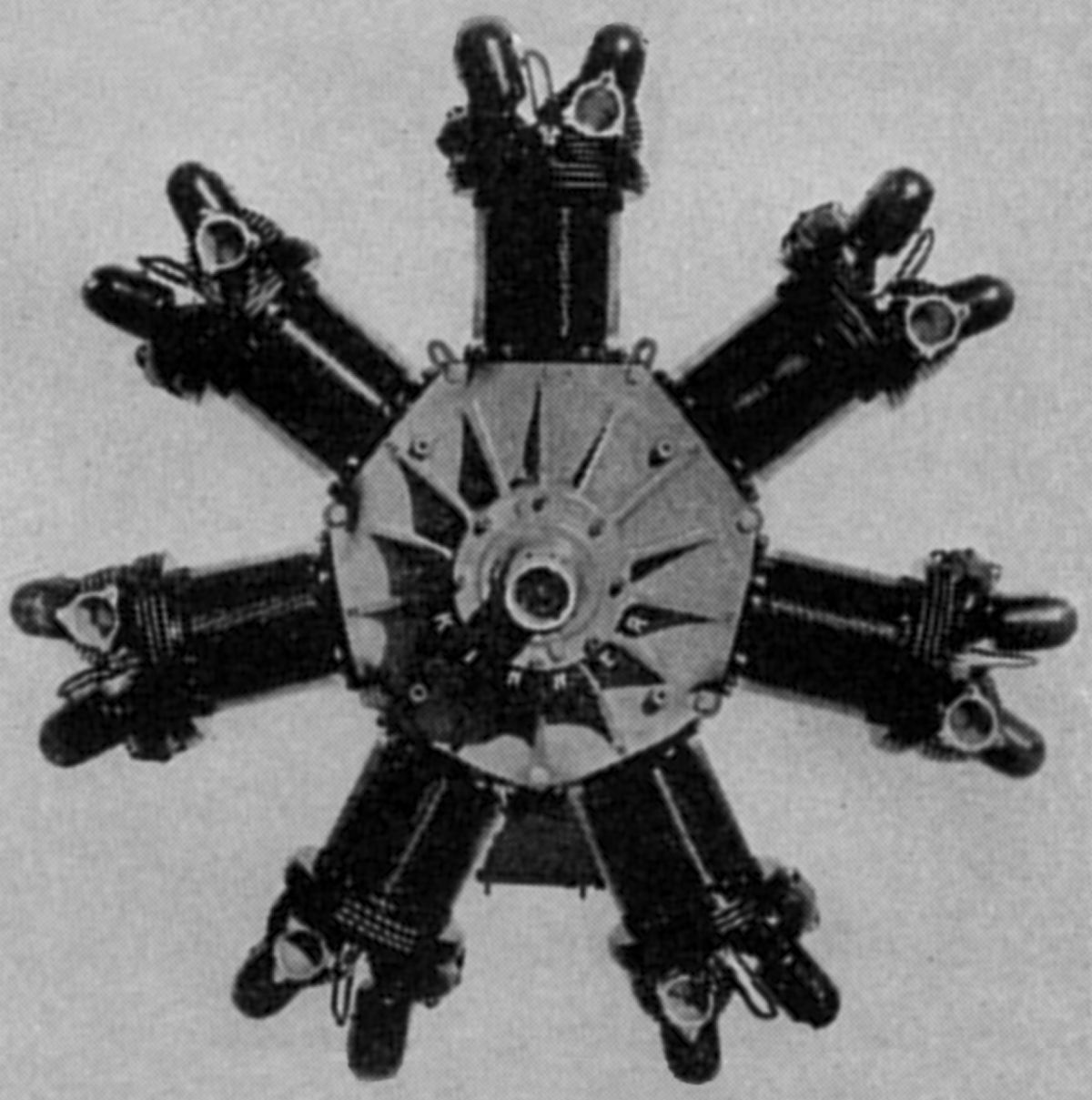
The 1934 Kinner C-7 was an improved seven-cylinder companion to the C-5. With a 5.625" (142.875 mm) bore, 6.000" (162.400 mm) stroke, 1,043.72 in³ (17.104 l) displacement and 5.25:1 compression ratio, Department of Commerce Approved Type Certificate No. 122, awarded on 28 Mar 1934, rated it 300 hp at 1,800 rpm on 73 octane fuel. Dry weight was 630 lb (286 kg), diameter was 48.313" (1,227 mm), length was 44.125" (1,121 mm) and the mounting bolt circle diameter was 20.000" (508 mm). While similar to the C-5 in general design, the Kinner C-7 incorporated many new features. The rocker box was cast integral with the rear-exhaust cylinder head, thereby eliminating oil leakage and permitting a more satisfactory cooling fin arrangement on the exhaust port side. The cooling fin area was again increased and arranged to lower cylinder head temperatures. The rocker arm had a roller-bearing axle, and a roller tappet was used. The crankcase front section, which was made up of two aluminum castings, had bosses for supporting an exhaust collector ring, built-in valve mechanism, and controllable-pitch propeller provisions. While it was proposed to use an engine-speed impeller for the induction system, supercharging provisions were also made. A crankshaft extension accommodated two magnetos, an electric starter, electric generator, fuel pump, vacuum pump, air pressure pump, two gun synchronizers and tachometer, each having its own mounting pad. Design provisions accommodated 6"-bore cylinders at a later date. An 11" (279 mm) induction system impeller, driven at crankshaft speed, had straight vanes. When using a General Electric type supercharger, this impeller was replaced by one that was driven through a gear train and clutch that protected the gears from injury when the engine was accelerated or decelerated. The lubrication system consisted of gear-type pumps that introduced oil under pressure into the crankshaft rear end. The scavenging pump had three gears, two inlets and two outlets. Excess oil was pumped from the auxiliary drive section, and from the crankcase sump. Oil from the scavenging pump was circulated around the crankcase impeller section before it was returned to the oil tank. Provision was made for a Cuno oil filter.
Unlike preceding Kinner models, the C-7 engine employed a two-piece crankshaft carried in three antifriction bearings. The solid master rod big end was fitted with a steel-backed copper-lead bearing; link rods were similar to those used in C-5. The two crankcase rear sections, which carried the auxiliaries, were removable as units. The electrical units were mounted on or above the engine center line; carburetor, fuel and oil pumps were mounted below.
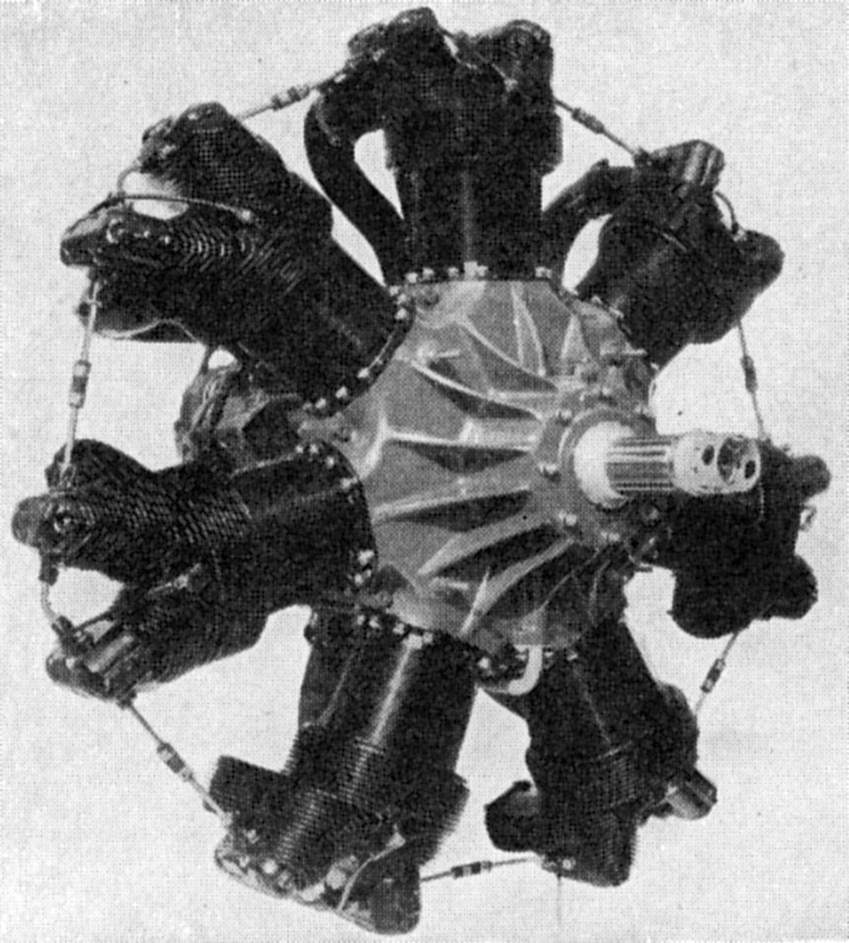
The Kinner SC-7, an improved C-7 was equipped with General Electric supercharger having a 9.7:1 impeller gear ratio. The cylinder head was new, with rear-facing exhaust ports. The cylinder head was screwed and shrunk onto the barrel instead of being bolted as in all earlier Kinner engines. The SC-7, with a 5.5:1 compression ratio using 73 octane fuel, was originally rated 370 hp at 1,900 rpm and 5,000 feet, with 400 hp available for takeoff. However, Department of Commerce Approved Type Certificate No. 175, issued on 5 Jun 1937, specified a 350 hp output. Bare dry weight, without propeller nut, magnetos or carburetor, was reported to be 650 lb (295 lb). Fuel and oil consumptions at rated power were 0.55 and 0.025 lb/hp/hr., respectively. The SC-7 diameter was 47.75" (1,213 mm) and its length was 45.41" (1,153 mm).
The Kinner BSC-7 employed a 6.0:1 compression ratio, required 80 octane fuel. Kinner gave 420 hp as the normal rated output at 2,200 rpm and 5,000 feet, with the takeoff rating 450 hp at 2,200 rpm.
 |
| Kinner GC-14 |
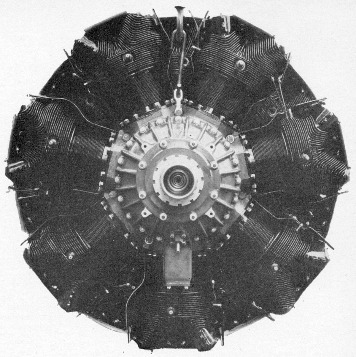
Early in 1939, Kinner announced the GC-14, a two-row air-cooled radial fourteen. GC-14 cylinders used cast aluminum-alloy heads and steel barrels, both being heavily finned. The aluminum-alloy pistons were forged, and aluminum alloy castings comprised the crankcase. Both models were equipped with Eclipse Series 32 inertia starter and shielded B.G. 4BS spark plugs.
The Kinner R-1830, a 14-cylinder two-row radial with a 5.500" (139.7 mm) bore and stroke, 1829.39 in³ (29.978 l) displacement and 6.5:1 compression ratio, was rated 840 hp at 2,400 rpm at 15,000 ft maximum, 650 hp at 2,200 rpm cruising, and 900 hp at 2,450 rpm and 36.5 inHgA manifold pressure for takeoff. A two-stage General Electric supercharger was driven at 7.3 times crankshaft speed. Recommended fuel was 87 octane. Fuel and oil consumptions at rated horsepower were 0.55 and 0.035 lb/hp/hr. Dry weight, without propeller hub and accessories, was 1,265 lb (574 kg). Diameter was 41.5" (1,054 mm) and length was 57" (1,448 mm). Ignition was supplied by two Scintilla F-14 magnetos, and the mixture was provided by a Stromberg NA-Y9A carburetor. An Eclipse R-10-B generator was fitted.
Kinner rated the twin-row R-2230, with its 5.875" (149.225 mm) bore and stroke, 2,229.67 in³ (36.538 l) displacement and 7.0:1 compression ratio, 1,050 hp at 2,400 rpm and 7,000 ft, 750 hp at 2,200 rpm cruising, and 1,200 hp at 2,560 rpm and 42 inHgA for takeoff. Weighing 1,350 lb (612 kg), minus propeller hub and accessories, its diameter was 43.25" (1,099 mm) and its length was 56.625" (1,438 mm). Specific fuel consumption at rated power was 0.65 lb/hp/hr. Aside from the use of an automatically lubricated valve gear and a geared single-stage General Electric centrifugal supercharger, this engine was practically identical to the R-1830. The R-2230 was fitted with two Scintilla F-14L magnetos, an Eclipse R-10-D generator, and the mixture was furnished by a Stromberg carburetor having an automatic mixture control.
The Kinner Airplane & Motor Corporation went bankrupt in 1937. O.W. Timm Aircraft purchased the aircraft division, and Kinner motor division chief John Gladden purchased the engine business. Gladden continued producing Kinner engines through WWII and even introduced some new models, still under the name Kinner. There is no evidence that the SC-7 or any later engines ever found an application or was produced. Gladden Products Company continues to hold the type certificates for all Kinner engines.
References
Unless otherwise noted, descriptions and images are from Angle, Glenn D, ed. Aerosphere 1939 (New York, New York: Aircraft Publications, 1940).
Send mail to
![]() with questions or comments about this web site.
with questions or comments about this web site.
![]()