The Deschamps Aircraft Diesel
Compiled by Kimble D. McCutcheon
Published 10 Jul 2018
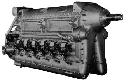
The Deschamps Diesel (Aero Digest) |
The Deschamps two-stroke/cycle Diesel engine was announced during the early part of 1934. It was the design of Desire J. Deschamps, formerly associated with the Minerva Company of Belgium, where he designed a rotary-valve aircraft engine. The Dechamps engine was built experimentally in the plant of the Lambert Engine and Machine Company at Moline, Illinois.
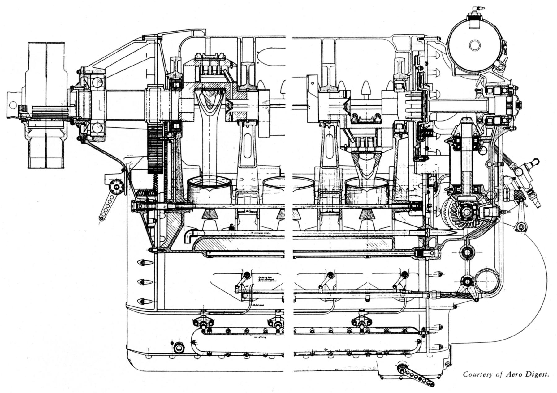
The Deschamps engine, one of the largest aircraft Diesel types proposed up to that time, was an inverted V-12, with two blocks of six cylinders 30° apart so as to give a compact power plant with small frontal area enclosed by a rectangle of 26.5" wide and 49.563" high. With a 6" bore and 9" stroke, the engine displaced 3,053.6 in³ and had a compression ratio of 16:1. The rated output was 1,200 hp at 1,600 rpm. The dry weight was reported to have been 2,400 lb, or 2 lb/hp. This weight included all auxiliaries – starter, air compressor, double fuel strainer, fuel booster pumps, fuel lines, superchargers complete with air intakes with their adjustment valves, torsional vibration damper and torque limiter protecting the gear drives and the overrunning clutch for the supercharger impeller. |
The first experimental Deschamps V-12 was made reversible so that it could be used both for dirigibles and airplanes. This feature caused a weight increase of approximately 45 lb. With a reversible engine in an airplane, it would be possible to use the propeller as a brake and shorten the landing ground run. Tests of a two-cylinder experimental engine of the same cylinder dimensions indicated that the V-12 would develop 1,200 hp at about 1,600 rpm. A normal continuous output of 900-1,000 hp was expected.
The cylinder blocks and crankcase comprised a single magnesium casting, the bearing supports being held by two transverse walls. Wet cylinder liners of nitralloy steel, hardened inside to 900/1,000 Brinell, were sealed by rubber rings that did not come in contact with the cooling liquid, thus making it possible to employ an ethylene glycol mix, if desired, instead of water. Support was provided for the exhaust collector surrounding the cylinder so that there was freedom for expansion without setting up undue strains in the casting. The radially ribbed pistons were of Y alloy, but all ether castings were of heat-treated magnesium alloy, except the cylinder heads, which were cast aluminum alloy in a single units for each six-cylinder bank.
 |
 |
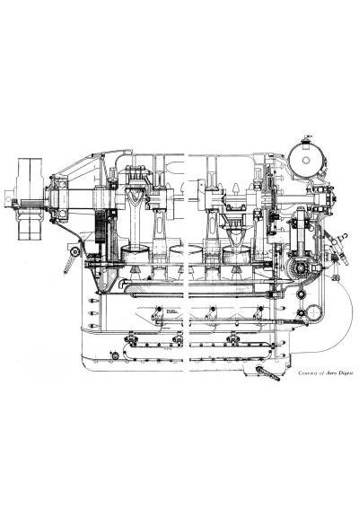
| Deschamps Diesel Longitudinal Section |
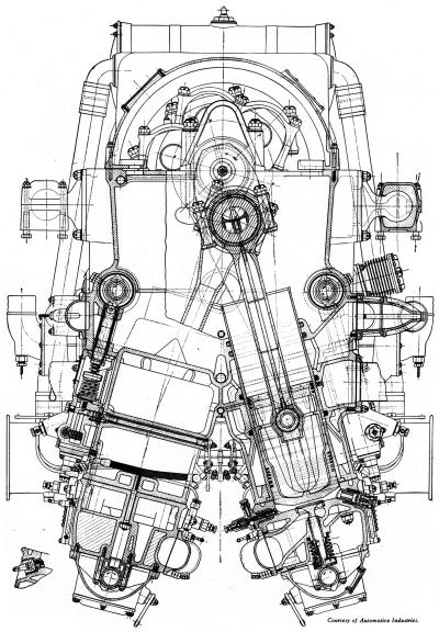
Deschamps Diesel Transverse Section |
Each bank of cylinders had an independent cooling, fuel, lubrication, and scavenging system, so that the powerplant virtually consisted of two engines with only the crankcase and the crankshaft common to both. If necessary, one bank of cylinders could be shut off and the ship landed on the remaining bank.
Each of the two centrifugal compressors provided scavenging air for one cylinder block. The impellers turned at 13.5 times crankshaft speed, delivering – in addition to the volume represented Its the piston displacement – an excess of 25% for scavenging purposes. With the air intake wide open, the compressors delivered scavenging air at a pressure of 12 psi. It was claimed that a pressure of 8 psi was all that was needed for good scavenging, therefore the excess 4 psi pressure could be used for supercharging. The pilot was permitted to adjust the output of the compressors by means of a butterfly valve on the air intake.
The compressed scavenging air entered the cylinders through two poppet valves. These opened and closed simultaneously, and two were used instead of one large valve so as to reduce the mass and permit the necessary quick opening and closing. The camshafts could be displaced axially by a decompression mechanism, and by sliding these shafts, a cam was moved over the valves to hold them open during the compression stroke. An automatic locking device held the shaft in one of two positions. Twelve ports in the cylinder walls near the bottom of the piston stroke permitted the exhaust gas to enter the collector surrounding the cylinder. This was so divided in the rear that it forced the burnt gas to travel in one direction.
The pistons incorporated a special feature to prevent a trouble often experienced with two-stroke engines – that of top rings sticking due to carbon formed by burnt oil being carried past them by exhaust gases. To prevent this from happening, the top ring was located sufficiently low that it was completely covered by the cylinder walls before the exhaust ports opened.
Special attention was paid to assure adequate cooling of the exhaust ports bridges to prevent liner distortion and assure long piston ring life. The top and bottom port edges are rounded to prevent the rings from catching on them.
In two-stroke engines with exhaust through cylinder ports, trouble was often experienced from excessive oil consumption and smoky exhaust, due to loss of oil through the ports. Deschamps addressed this by cutting a small horizontal groove in each cylinder liner about 1/2" below each port, a little shorter than the width of the port. At the center of this groove was a 0.125" hole through the liner, which emptied into a groove cut all around the cylinder casting. The grooves in all twelve cylinders communicated through drilled passages with a central tube connecting to a vacuum pump, thus preventing waste of oil. Since the grooves below the ports were not quite as long as the width of ports, some of the oil remains on the piston, but it is carried up over the lands, so that the upper end of the liner is still adequately lubricated. The degree to which the pistons are stripped of oil can be easily regulated by changing the vacuum, which was produced by a special double vane-type of pump of constant suction.
One novel engine feature was a method of locking the inner thrust bearing race without cutting a screw thread on the propeller shaft adjacent thereto (always a source of weakness). A two-piece threaded sleeve was located between the inner race and a shoulder on the shaft, and the customary lock nut screws over that sleeve. When the nut was tightened the sleeve is pulled against the shoulder on the shaft, while the nut ends up against the inner race, thus assuring a secure locking effect. Means were provided to prevent the sleeve from turning while the lock nut is being screwed on or off. A particularly attractive feature of the device was that the threaded sleeve need not be a close fit in the space provided for it on the shaft. This innovation is the subject of U.S. patent 2,113,017.
In order to avoid the accompanying difficulties of operating fuel pumps at engine speed in a two-stroke engine, double pumps in 180° phase relationship were employed. The camshaft, which operated the plunger, turned at one-half engine speed, hence the two elements of the double pumps delivered fuel alternately to the cylinder nozzles. The two nozzles in each cylinder were placed opposite one another, but were staggered so as to direct the fuel spray tangentially and promote a swirling of the compressed air. The pressure of full injection was approximately 3,500 psi. It was claimed that there had been no serious difficulty in balancing the spring loaded nozzles so each delivered almost exactly the same quantity of fuel. The problem of idling, which was sometimes quite difficult in certain Diesel-type engines, seemed to have been overcome in the Deschamps design. Ordinarily, at low speed with no load, the amount of fuel to be injected is so small that it can no longer be handled by the fuel pump, and an engine runs unevenly or may finally stop. While cutting out some cylinders may permit pumps to inject enough fuel in the cylinders in operation to keep the pumps working, it nevertheless may cause an engine to run roughly at idling speeds. In this design, the fuel pumps were provided with a valve that could be closed to stop the delivery of fuel to one of the cylinders of the double pumps. Therefore, instead of having an injection of fuel at each power stroke, it occurred on alternating strokes, with the result that all cylinders fired in proper sequence and remained at corresponding temperatures.
Oil was delivered to the bearings under a pressure from 80 - 100 psi by two pressure pumps. Two scavenging oil pumps were located in the overhead camshaft covers, and these delivered into a line connecting the large scavenging pumps with the tank. A vacuum pump was employed to draw, from around the piston, any excess oil that otherwise might be lost through the exhaust ports. There were no outside oil lines, and the strainers and pumps could be removed without removing any oil connections.
A Lanchester type torsional vibration damper was incorporated on the crankshaft rear to protect the gear drives. Combined with it was a clutch that would slip momentarily under sudden changes in torque, and this was termed a torque limiter. The driven member of the latter terminated in a tubular shaft that was splined at the end for the driving member which, in turn, through eight coil springs under tension, drove the central gear. This gear was supported by a ball and a roller bearing, and not mounted on the tubular shaft. A vertical shaft was driven from the central bevel gear at twice engine speed, and it in turn drove the horizontal shaft from which all the auxiliaries were driven.
In making the engine reversible, water pumps, oil pumps and supercharger automatically ran in the same direction, regardless of the direction of crankshaft rotation. Two miter gears on the horizontal shaft meshed with a gear near the lower end of the vertical shaft. These gears were not keyed, but were mounted upon ball bearings and drove the shaft by means of roller clutches. Consequently, one locked as the shaft turned clockwise, the other as it turned anti-clockwise, with the unlocked clutch running idle in the opposite direction at double speed.
The General Electric centrifugal superchargers were driven normally at 21,600 rpm through overrunning roller clutches. A small portion of the air entering the superchargers was taken from the engine crankcase as a means of providing ample ventilation and burning any fuel vapors escaping past the pistons.
The connecting rods were of the fork-and-blade variety, and both rod types had shanks of tubular section. A tube placed along the axis of the central rod carried oil to the piston-pin. The hollow crankpins were provided with special plugs to centrifugally separate any heavy foreign substances in the oil before it entered the big-end bearings.
Starting was by means of compressed air from a tank supplied by a small two-stage Heywood compressor. An air distributor, mounted at the rear end of the left-hand cylinder head, was driven from a camshaft. Air entered each cylinder at the proper moment through its automatic valve. This distributor was double for starting the engine in either direction, although there was only a single line from the distributor to each cylinder. The direction of starting was controlled by a two-way cock before opening the central valve. The engine turned at 1,200 rpm under compressed air without relieving the compression, although greater speed could be secured by decompressing the left-hand cylinders and starting the engine through the right-hand cylinders. Glow plugs were provided in the right-hand cylinders for starting in cold weather when needed.
The early-to-mid 1930s were tough times for aircraft engine manufacturers, and while the complete Deschamps V-12 engine was built, development work on it was interrupted by the death of the financial backer. It is not known whether the project was completed or ever flew. Deschamps went on to work on fuel injection systems for Eclipse, Bendix, Hydroaire and even his own Deschamps Fuel Injection Company. He was awarded 21 U.S. patents.
Acknowledgements
Thanks are due to Paul of the Revs Institute, Bud Wheeler and Dan Whitney, who contributed and conveyed the material used in this article.
Bibliography
Angle, Glenn D, ed. Aerosphere 1939, 1940. Aircraft Publications, New York.
Heldt, P.M. "Largest Aircraft Diesel is Inverted V-12 with Predicted 1,200 hp Output" Automotive Industries, 5 May 1934, 555-557.