Selected Early Engines
Union, Universal Test Engine
Compiled by Kimble D. McCutcheon
Published 27 Jun 2023; Revised 2 Jul 2023
Union
|
|
|
|
|
|
| Union 2-6 Airship Engine (NASM) | |||||
The Union Gas Engine Company of Oakland, California, designed the Union 2-6, a water-cooled vertical six for use in airships and dirigibles. In 1917, it became the first engine to pass a U.S. government 50-hour type test; in 1919 it powered the U.S. Navy C-5 airship during its record trans-Atlantic flight. With a 4.75" (121.29 mm) bore, 6.5" (165.10 mm) stroke and 691.10 in³ (11.325 l) displacement, it was rated 120 hp at 1, 350 rpm and weighed 485 lb (220 kg). It was 65" (1,651 mm) long, 17" (432 mm) wide and 40.75" (1,035 mm) high. Fuel and oil consumptions were 0.558 and 0.124 lb/hp/hr. The individual steel cylinders barrels had cast-iron heads and copper water jackets that were pressed into place. The overhead camshaft one inlet and one exhaust valve in each cylinder head via rocker arms. The six-throw seven-main-bearing crankshaft attached H-section connecting rods. Two gear pumps maintained 40 ‑ 50 psi oil pressure at the bearings, and either Berling or Dixie magnetos supplied dual ignition. An example at the New England Air Museum was restored to running condition in may 2002 by AEHS Member Sal Salomon.
Universal Test Engine
 |
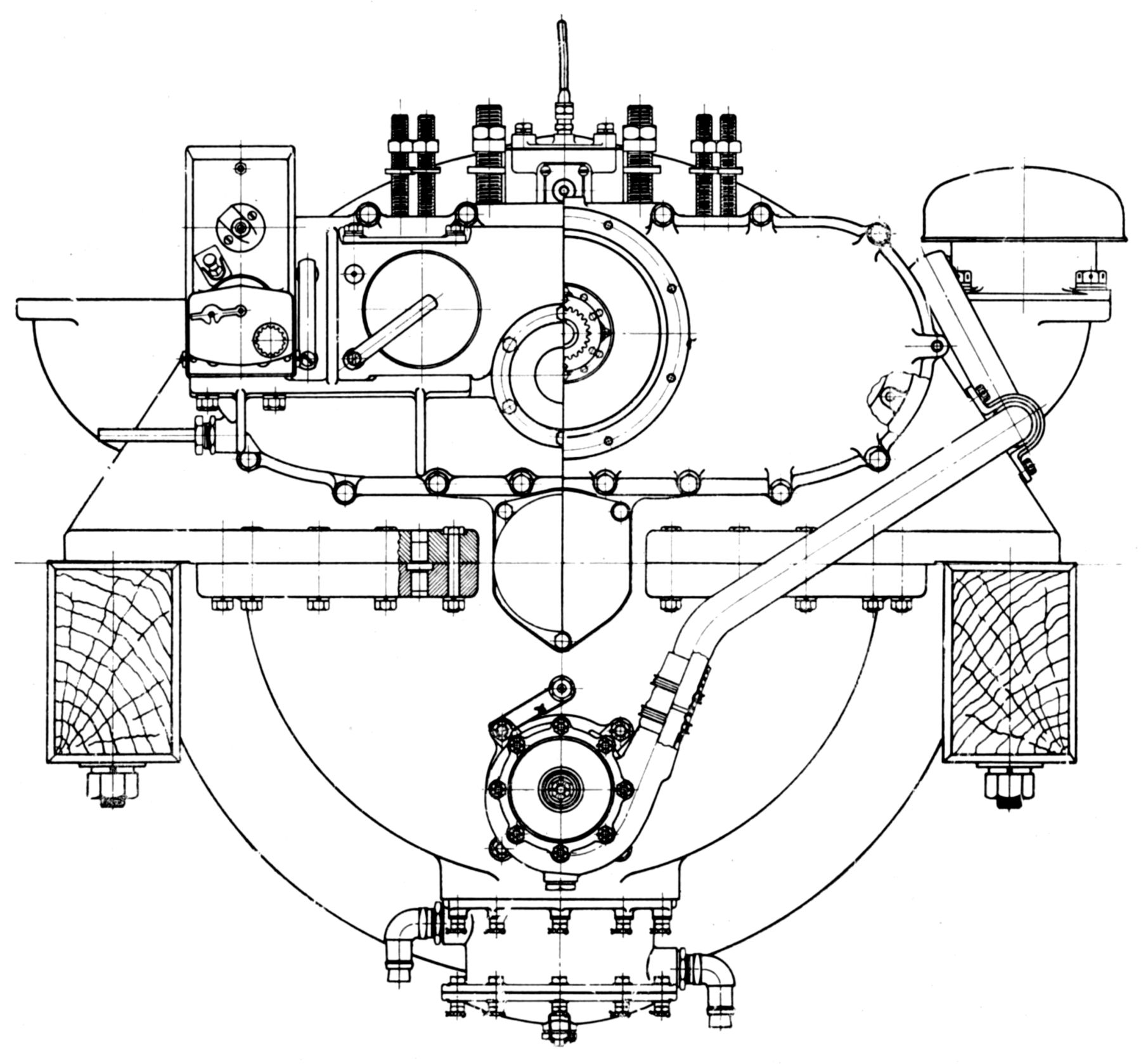 |
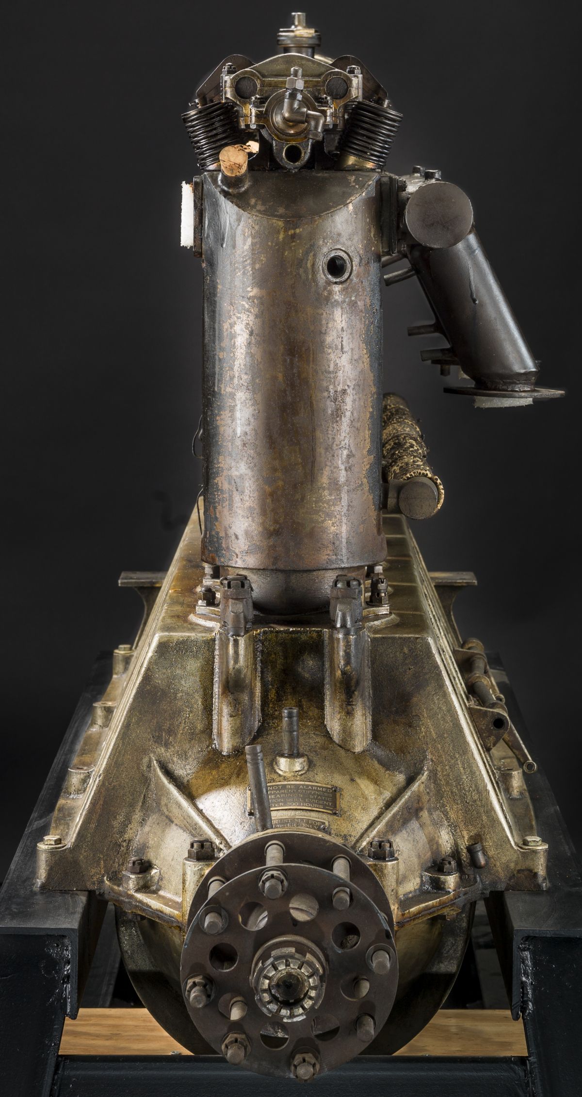
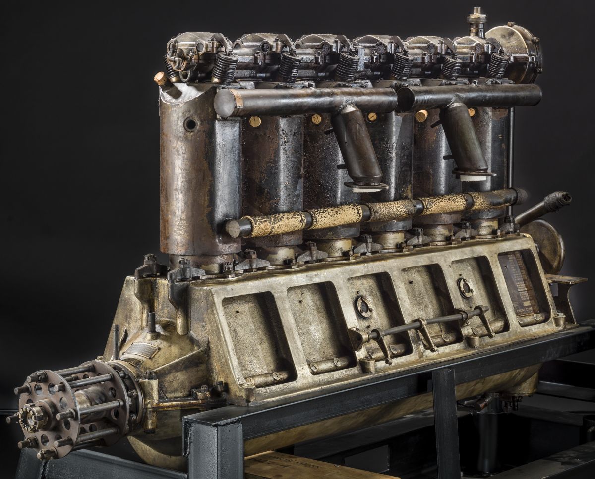
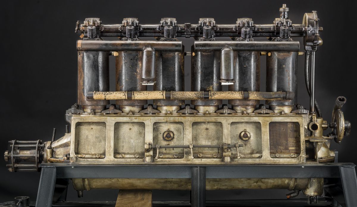
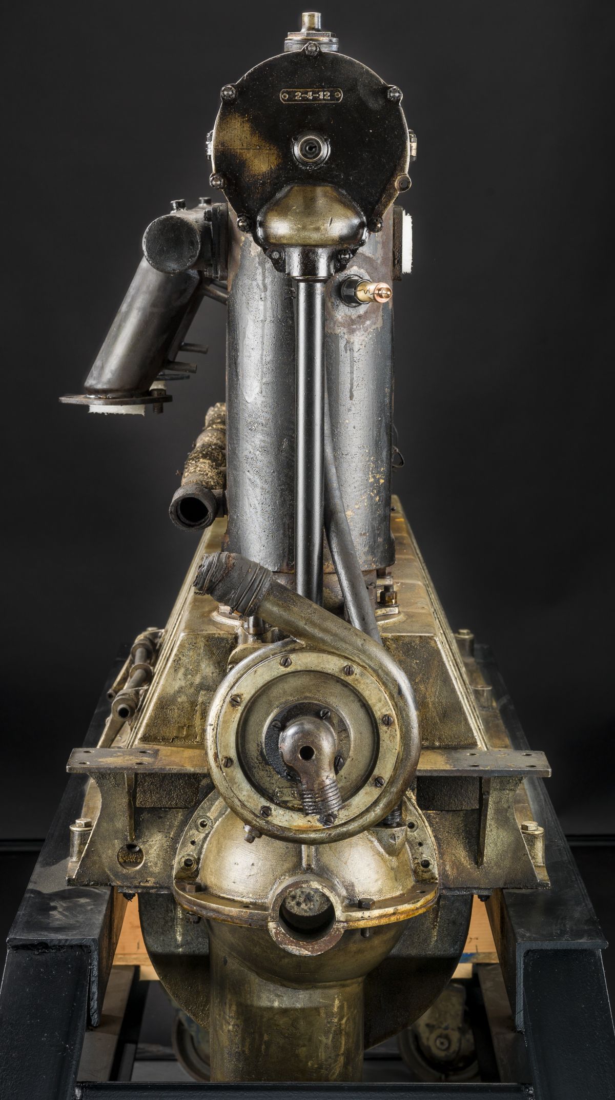
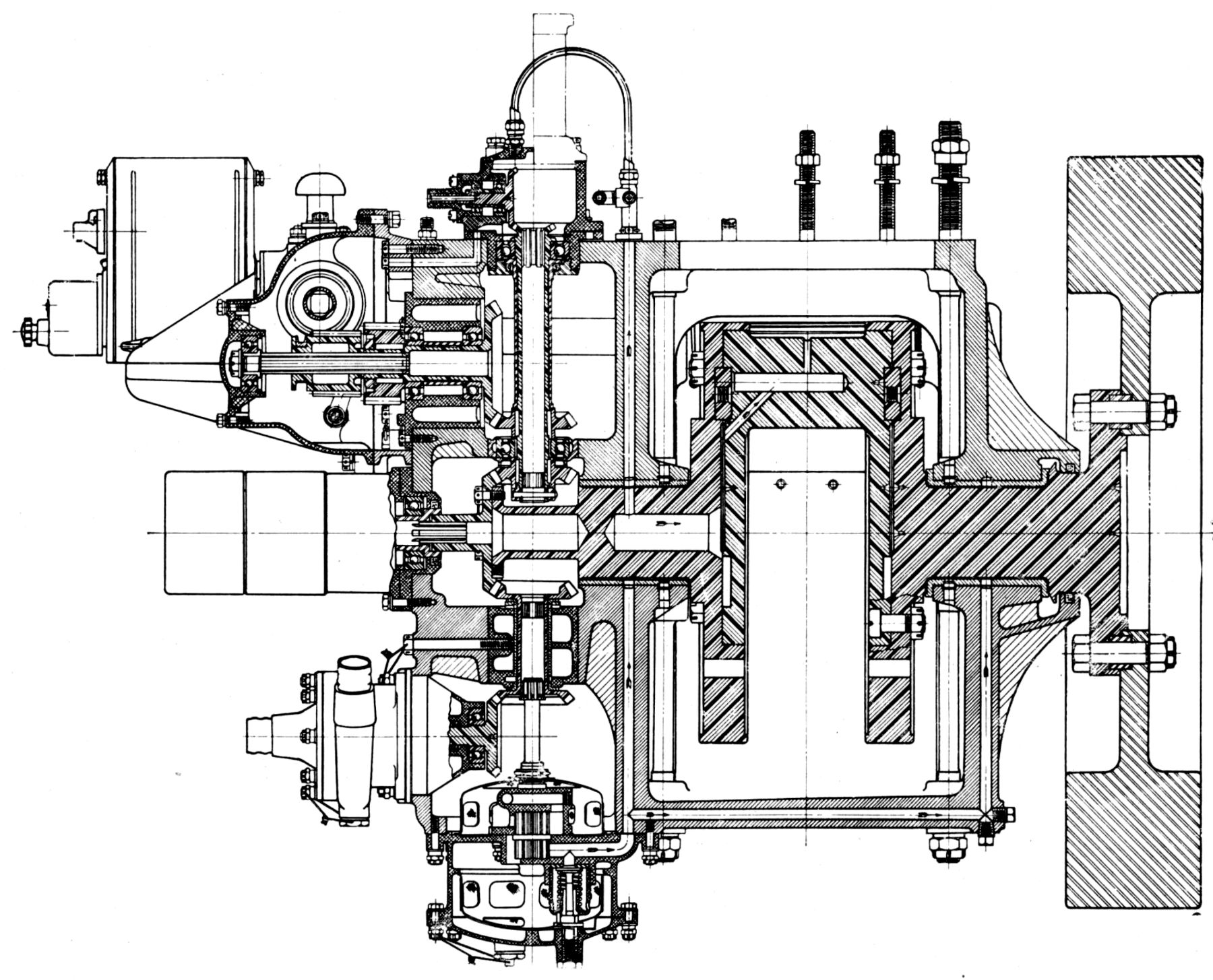
| Longitudinal Section, End Views (A39) | |
The Universal Test Engine was an was enormously useful test rig for aircraft engine cylinder development. Four examples were designed and built during 1919 by the U.S. Army Air Service Engineering Division at McCook Field, Dayton, Ohio. This allowed the Power Plant Laboratory to operate at least two engines almost continuously.
The Universal Test Engine was intended to test any single air- or water-cooled cylinder having a 4" ‑ 8" bore and 4" ‑ 10" stroke. The engine was heavily constructed to ensure rigidity and to prevent serious damage if parts under test failed. A means existed to vary the compression ratio through a wide range. From one to four spark plugs could he used with either magneto or battery ignition. Spark synchronization adjustinent was easily accomplished, and the advance/retard mechanism was controlled by one lever.
The universal crankshaft was a patented feature (US 1,385,768) that permitted changing the stroke. The shaft was made in three sections, the center section having a crankpin interposing two discs that slipped into eccentric recesses in the two large outer discs that were integral with the main journals. The three sections were bolted and doweled together. The large discs afforded a suitable surface for attaching counterweights, and served to supplement the action of the regular flywheel.
Two standard flywheels were sufficient for the range of cylinders and speeds employed. A standard connecting rod for each stroke length in even dimensions was designed for cylinders employing any compression ratio within the prescribed limits. A camshaft (US 1,583,949) situated in each side of the cast-iron crankcase operated push-rod-controlled valve gears, and a hollow splined shaft was arranged to receive the splined end of a vertical shaft for driving an overhead camshaft; no valve gear alterations were necessary when varying the stroke or compression ratio. Cams for either overhead or side camshafts were made separately and attached to the shafts by splines.
References
Angle, Glenn D, ed. Aerosphere 1939 (New York, New York: Aircraft Publications, 1940).
Anble, Glenn D, ed. Airplane Engine Encyclopedia (Dayton, Ohio: Otterbein Press, 1921).
Image Sources: A39 = Aerosphere 1939; AEE = Airplane Engine Encyclopedia; Flt = Flight Magazine; NARA = U.S. National Archives and Records Administration; UKNA = United Kingdom National Archives; Wiki = Wikimedia Commons (mouse over for details).
Send mail to
![]() with questions or comments about this web site.
with questions or comments about this web site.
![]()