Selected Early Engines
Thomas, Tips, Tosi, Trebert
Compiled by Kimble D. McCutcheon
Published 4 Jun 2023; Revised 27 Jun 2023
Thomas [A39, Wikipedia]
English immigrant brothers William T. and Oliver W. Thomas founded the Thomas Brothers Company in Hammondsport, New York, during 1910. Competitors of Glenn Curtiss, they built the Thomas Brothers Hydro-Aeroplane in 1912. The company became the Thomas Brothers Aeroplane Company and moved to Ithaca, New York, in 1914, where they built aircraft and aircraft engines as the Thomas Aeromotor Company. Financial difficulties led to a 1917 merger with the Morse Chain Company, forming the Thomas-Morse Aircraft Corporation of Ithaca. In 1929, Thomas-Morse was absorbed by the Consolidated Aircraft Corporation and ceased business altogether in 1934.
The first Thomas engine, built in 1912, was, a water-cooled vertical four rated at 120 hp.
|
|
|
|
|
|
|
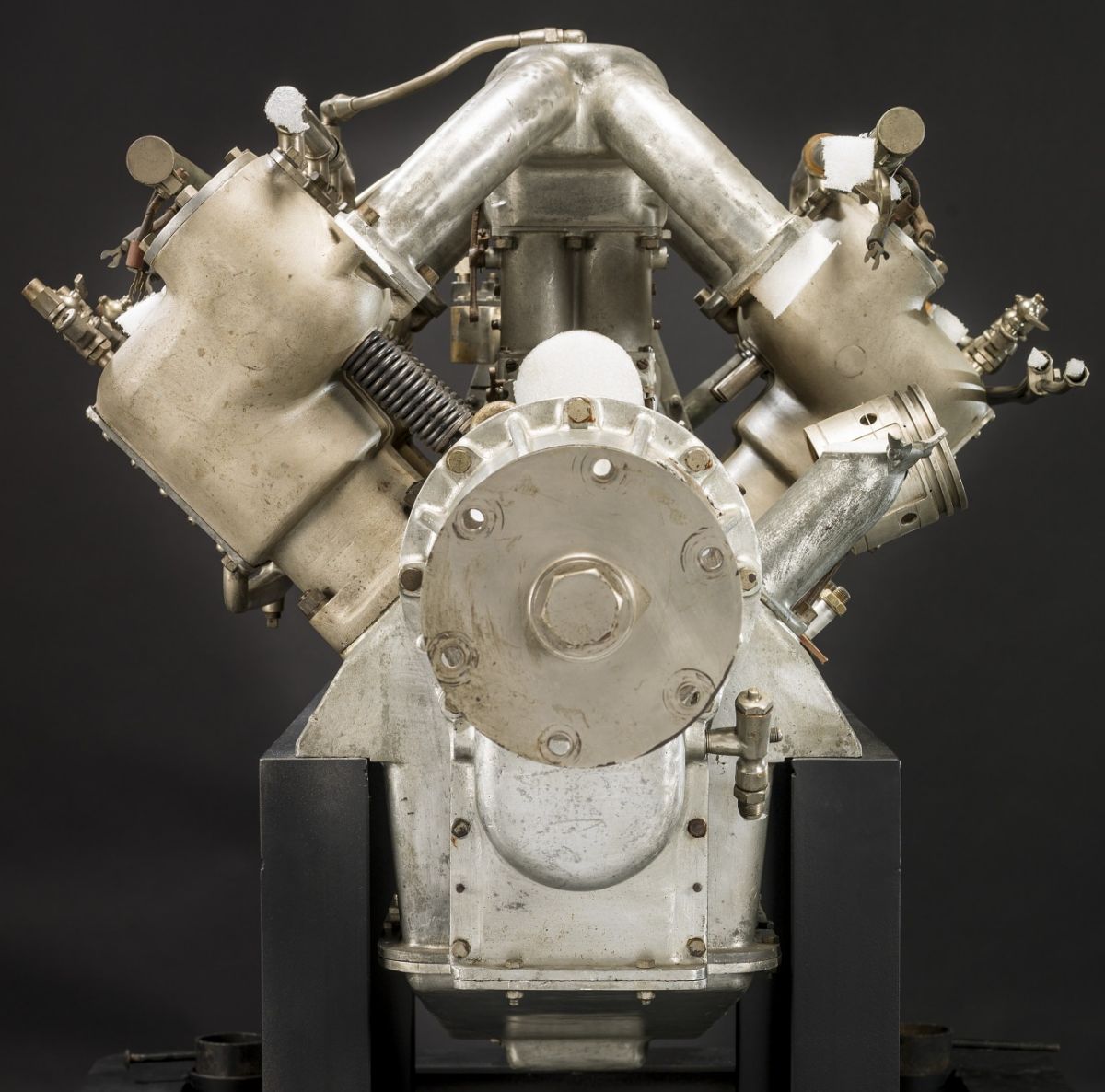
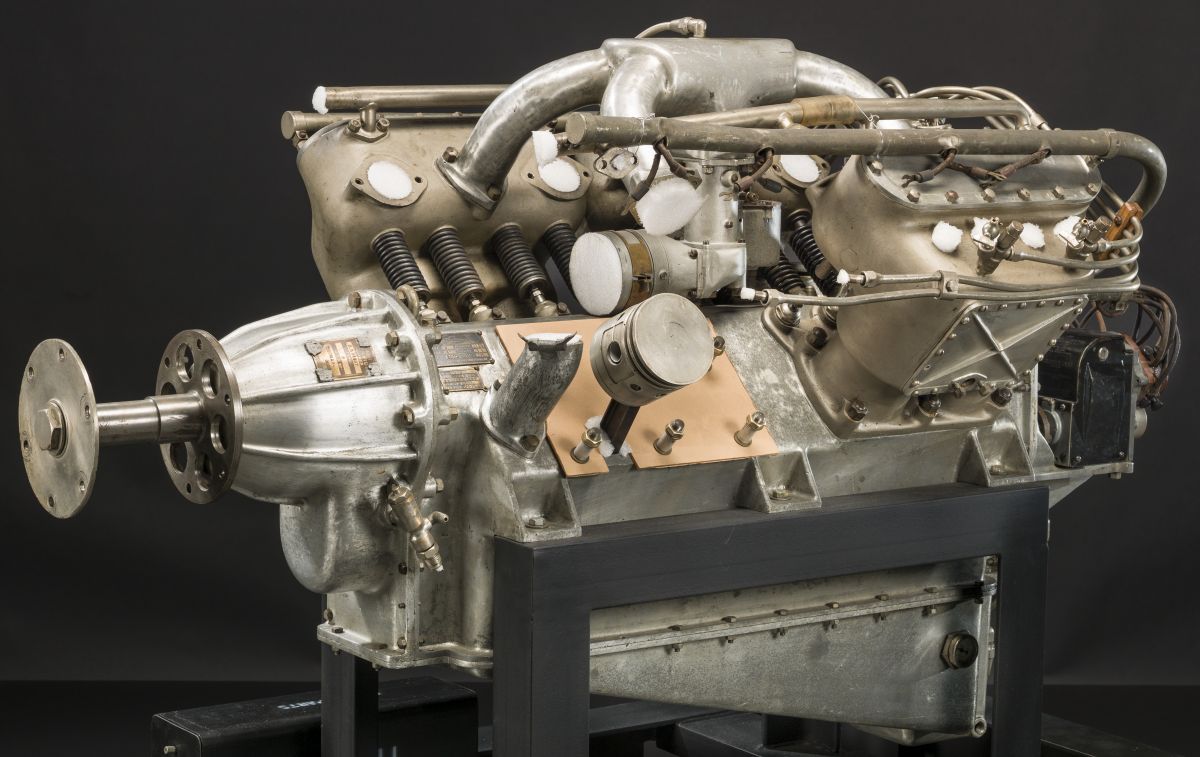
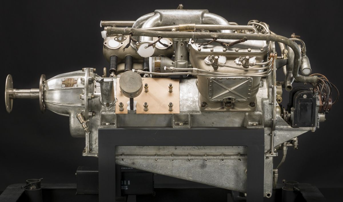
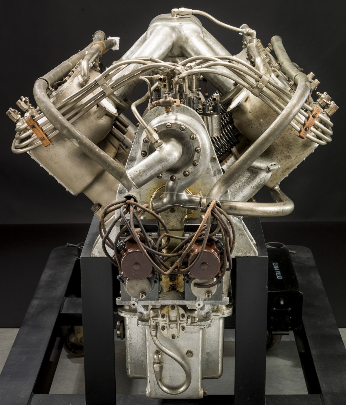
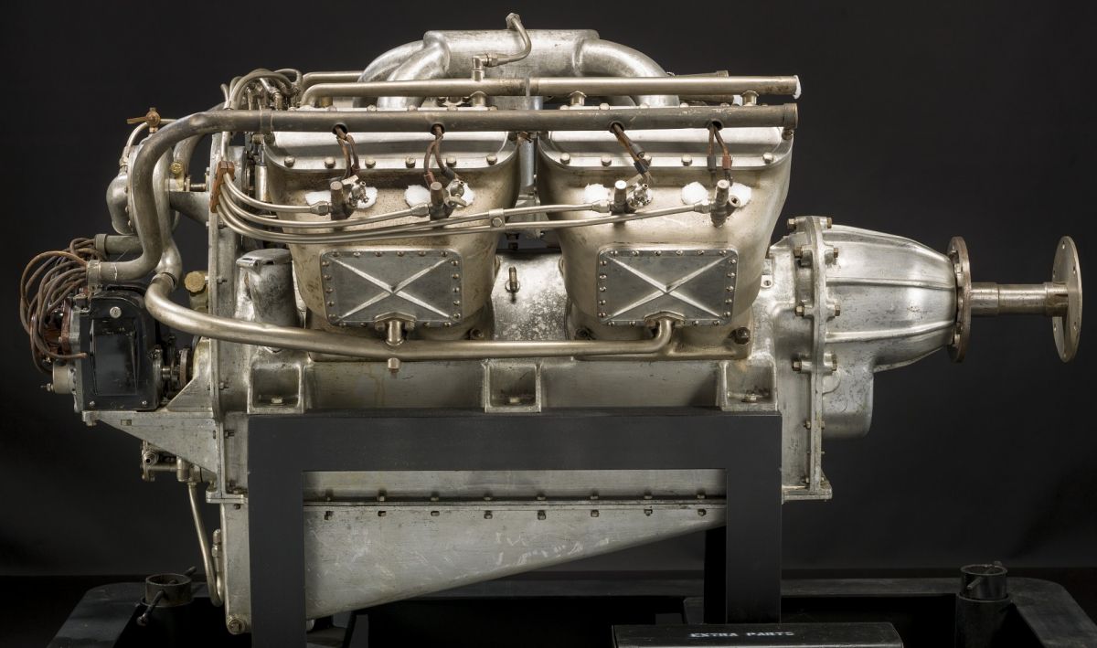
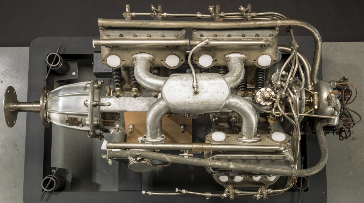
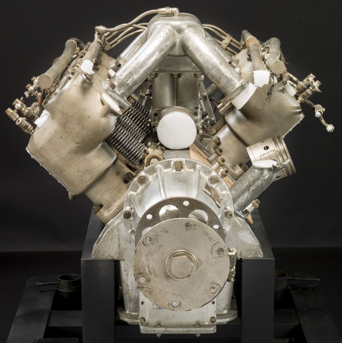
| Thomas Model 8 (NASM) | ||||||
The Model 8 was a 5:3-geared water-cooled 90° V-8 with a 4.000" (101.6 mm) bore, 5.500" (139.7 mm) stroke and 552.92 in³ (9.061 l) displacement that produced 135 hp at 2,000 rpm and weighed 600 lb (272 kg). The L-head cylinders were cast in pairs with integral water jackets from grey iron. The valves had a 2.125" (54 mm) clear diameter and 0.4375" (11.11 mm) lift. The four-throw crankshaft had three main bearings and the connecting rods were arranged on the crankpins side-by-side. The lubrication system was pressure-fed, a 2.0" (50.8 mm) duplex Zenith carburetor furnished the mixture, and two four-cylinder magnetos supplied ignition. The Model 8 was the first aircraft engine equipped with a self-starter.
 |
 |
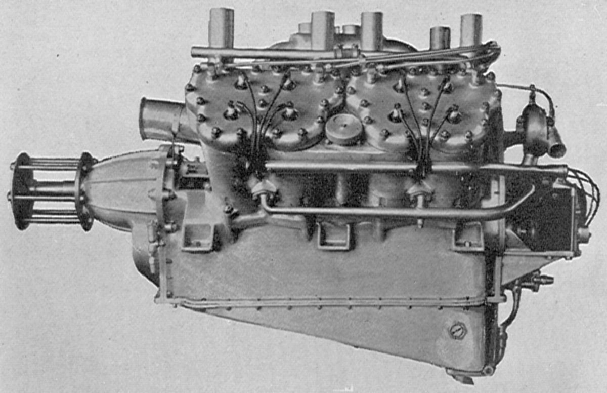
| Thomas Model 88 (AEE) | |
A more refined Model 88 was marketed in 1916. With a 4.125" (104.78 mm) bore, 5.500" (139.7 mm) stroke and 588.02 in³ (9.636 l) displacement, it was rated 150 hp at 2,000 rpm and weighed 525 lb (238 kg). Although similar to the Model 8, it used cast aluminum alloy lined with steel sleeves for the paired cylinders and the cylinder heads were detachable. Fuel and oil consumptions were 0.6 and 0.06 lb/hp/hr. Duplex Zenith carburetors supplied the mixture, and a gear pump maintained a 50-psi oil pressure at the bearings. Two Dixie magnetos supplied ignition.
The Model 890 was a 16:11-geared water-cooled V-8 with a 4.8125" (122.24 mm) bore, 6.000" (152.4 mm) stroke and 873.12 in³ (14.308 l) displacement that was rated 250 hp at 2,200 rpm and weighed 590 lb (268 kg). The L-head type cylinders were cast with integral water jackets from aluminum alloy in blocks of four and fitted with cast iron liners. The detachable cylinder heads had inlet and exhaust valves with 2.8125" (71.44 mm) clear diameters. The four-throw three-main-bearing crankshaft had side-by-side H-section connecting rods with the big-end bearing white metal applied directly to the steel. The aluminum pistons were ribbed underneath the head and fitted with two top compression rings and one lower oil-scraper ring. A Stromberg duplex carburetor supplied the mixture. Fuel and oil consumptions were 0.54 and 0.04 lb/hp/hr. Two Dixie magnetos provided dual ignition and a gear pump maintained oil pressure. Either a hand starting magneto or a Christensen air starter could be supplied.
Tips
 |
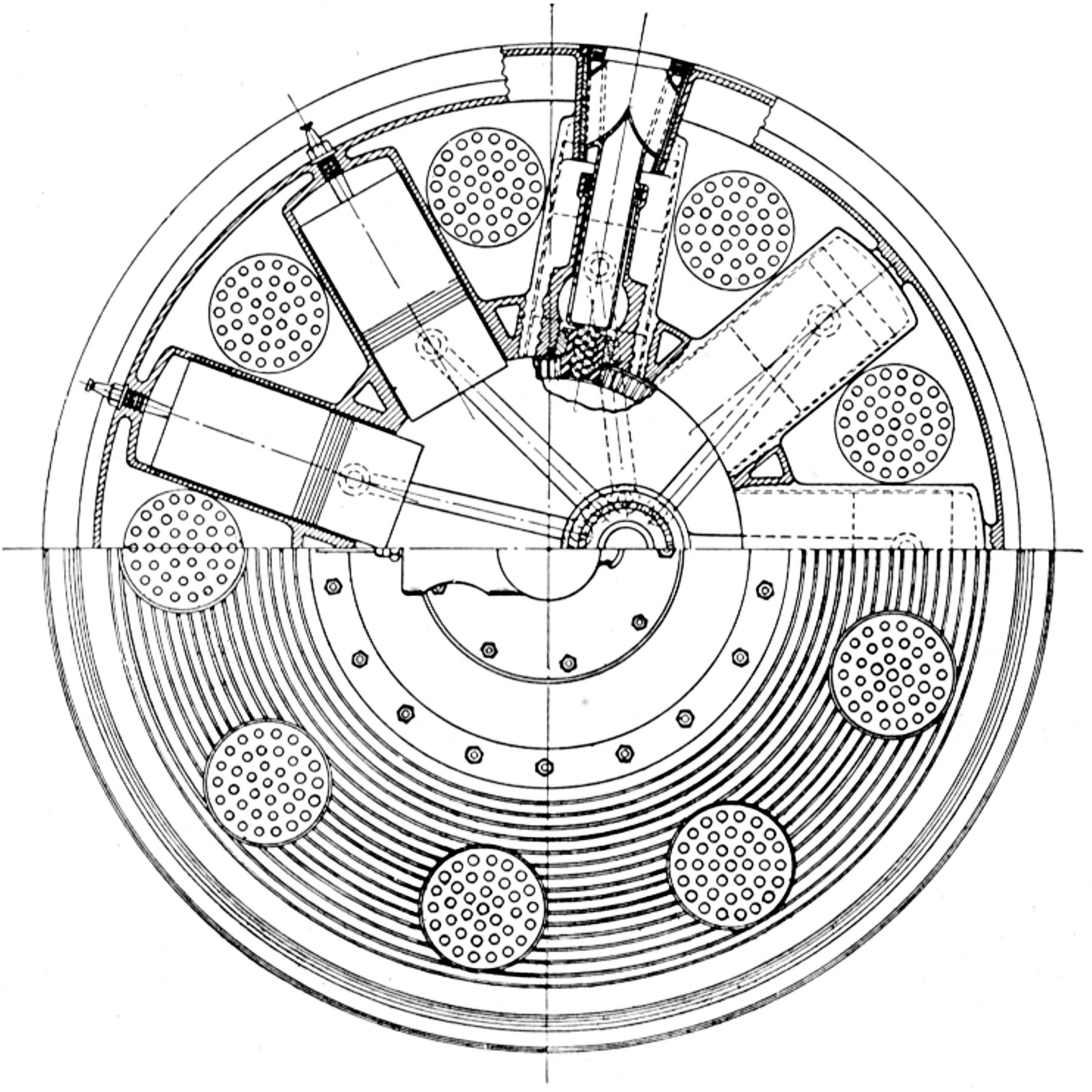 |
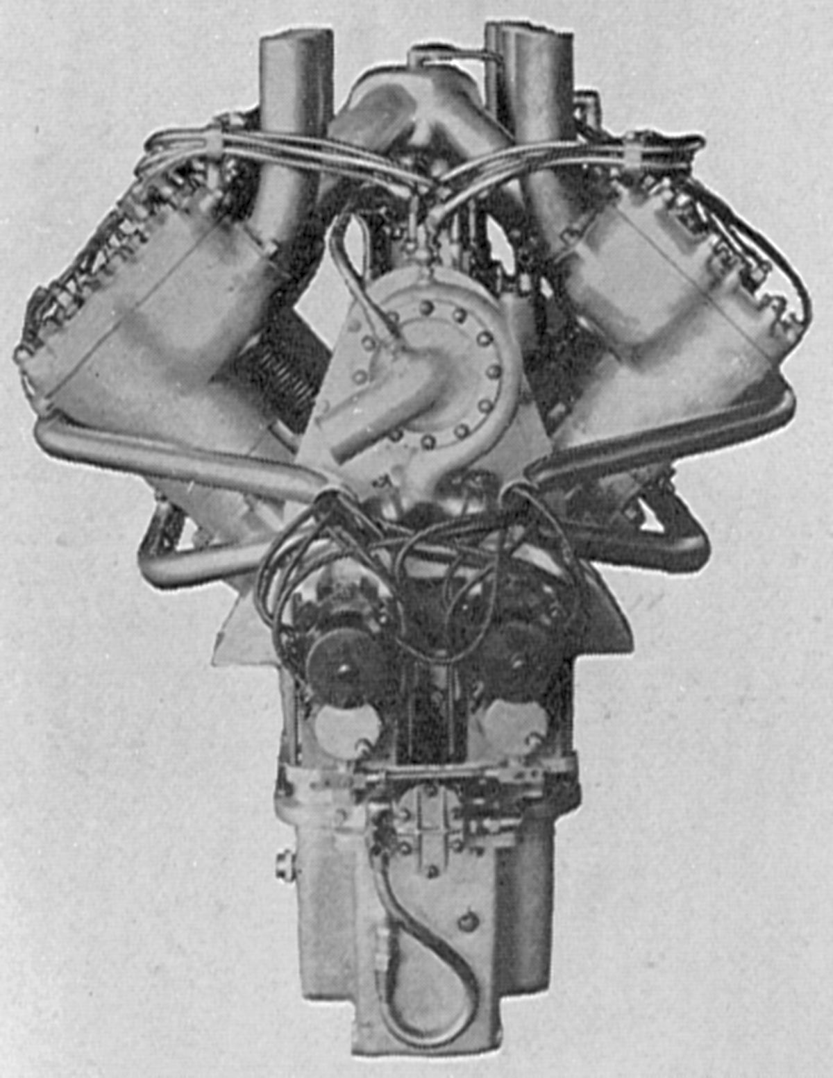
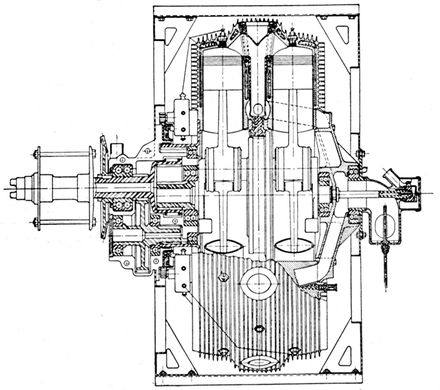
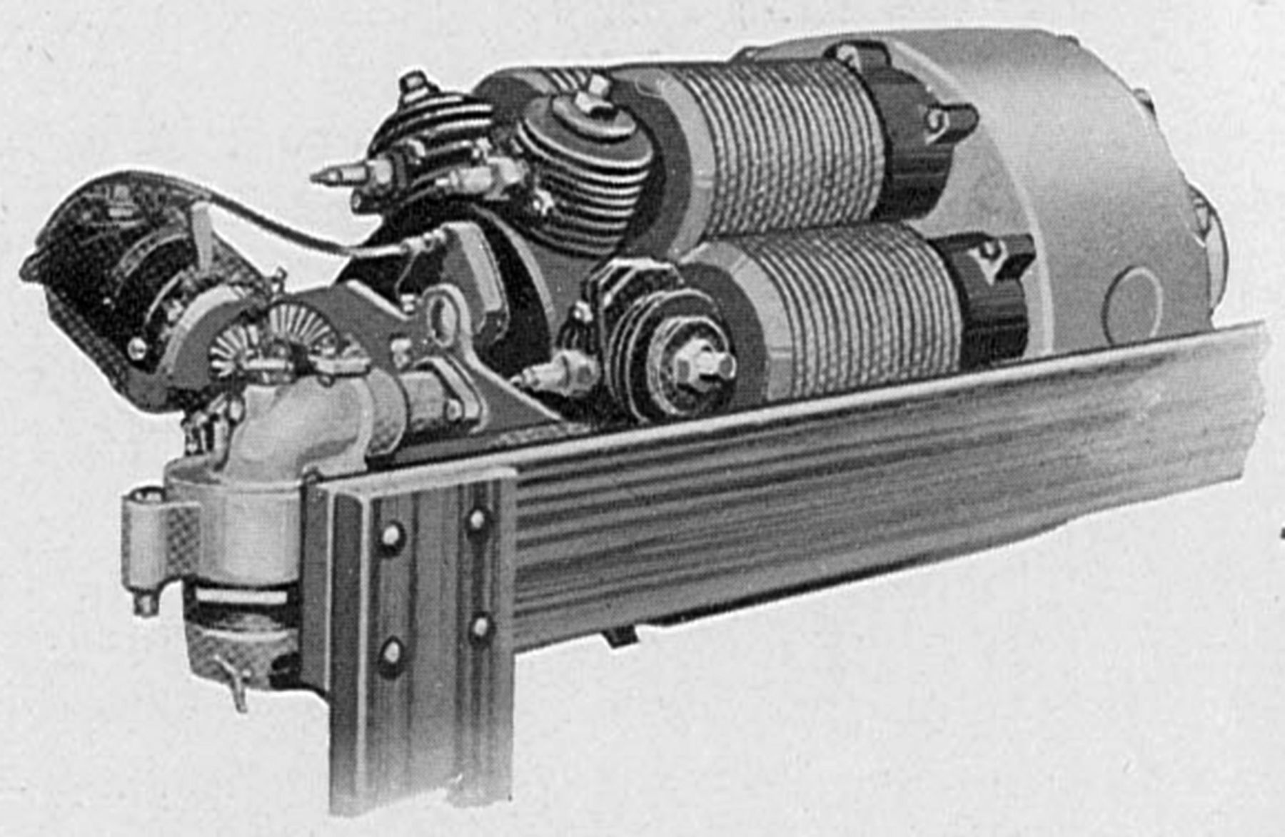
| Tips Differential Rotary (AEE) | |
Maurice Tips built his first rotary aircraft engine, a geared differential with both water and air cooling, in Belgium around 1911. As the cylinders/crankcase slowly rotated, the cooling water circulated via convection between the cylinder cooling jackets and nine tubular radiators placed between the cylinders. A self-adjusting water-cooled self-lubricated tapered rotary sleeve valve was driven from the main planetary gear mechanism. Each valve sleeve operating in a cast iron housing was lubricated with graphite and supplied a cylinder pair with both inlet and exhaust. William Pearce provides detailed Tips engine coverage in his superb article.
Tosi
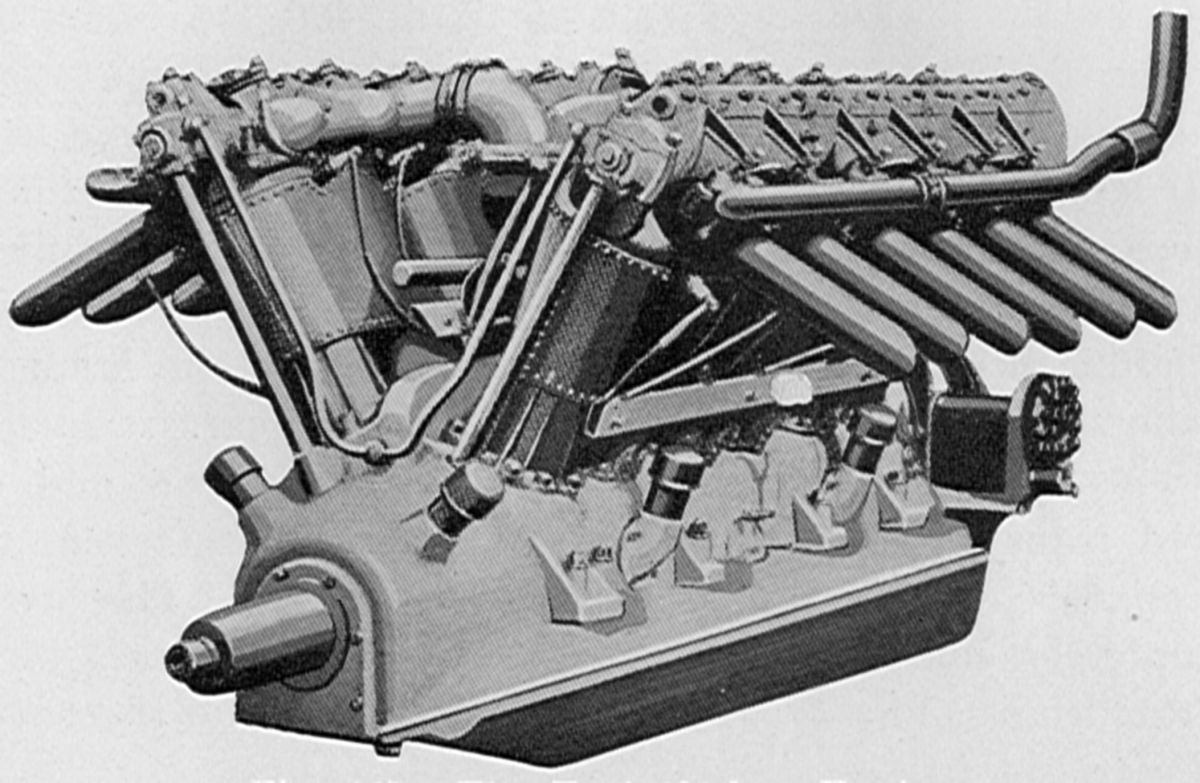 |
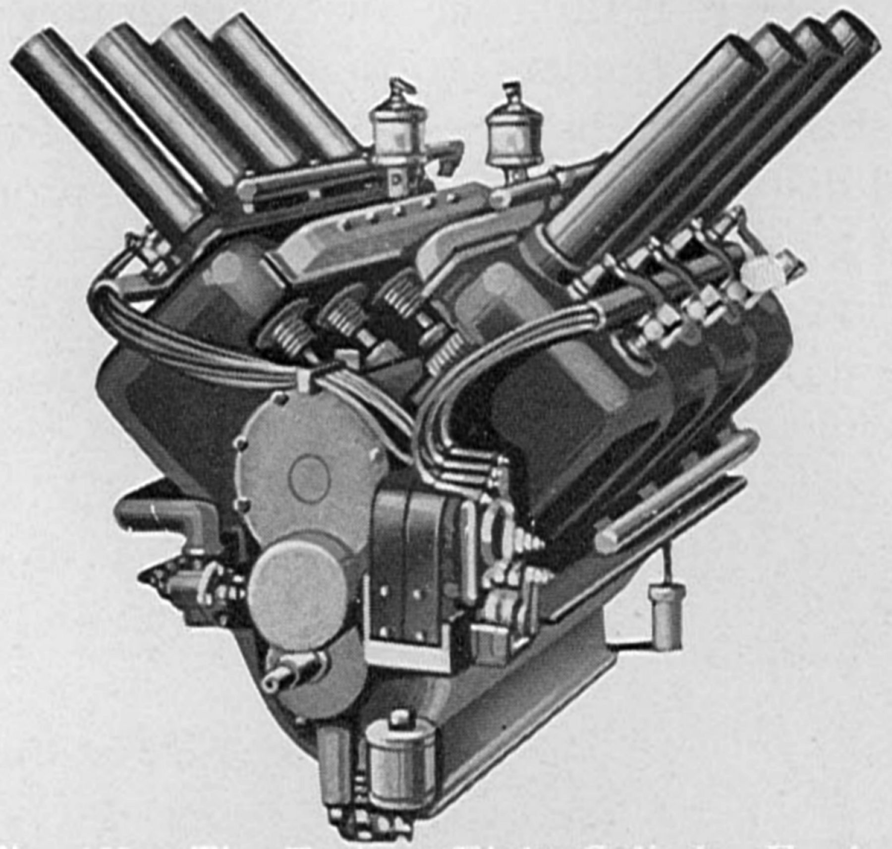
| Tosi 400 hp V-12 (AEE) |
In 1876 the young engineer Franco Tosi (1858 ‑ 1898) joined Cantoni Krumm & C. in Legnano, Italy, to manage its steam engine and boiler manufacturing. Tosi studied and built reciprocating steam engines that gained Italian and international reputation.
In 1884, Tosi became the sole owner of the Tosi Works. Before WWI, the Tosi Works increased military airplane engine production by building, under license, the Isotta-Fraschini V4-B. Later, Tosi built its own design, which was similar to the Isotta-Fraschini.
The Tosi Model V-12 was a direct-drive water-cooled 60° V-12 with a 130 mm (5.118") bore, 190 mm (7.480") stroke, 30.263 l (1,846.76 in³) displacement and 5.5:1 compression ratio. Rated 400 hp, the engine developed 440 hp at 1,600 rpm and 500 hp at 1,700 rpm. Weight was 550 kg (1,212 lb). length was 1,448 mm (57"), width was 884 mm (34.8"), and was height 940 mm (37"). Fuel and oil consumptions were 0.478 and 0.026 lb/hp/hr. Two duplex carburetors were situated in the Vee. Pressure lubrication was employed, and two twelve-cylinder magnetos supplied dual ignition. The cylinders were made in pairs and encased in street-steel water jackets secured by screws. Single inlet and exhaust valves were operated through rocker arms and an overhead camshaft. The six-throw four-main-bearing crankshaft used fork-and-blade connecting rods with tubular shank sections. The aluminum pistons were fitted with three compression rings above the pin and a single oil scraper ring below the pin.
Franco Tosi Meccanica, as it is now known, is still located in Legnano near Milan. It concentrates on turbine, boiler, heat exchanger and pump production.
Trebert
 |
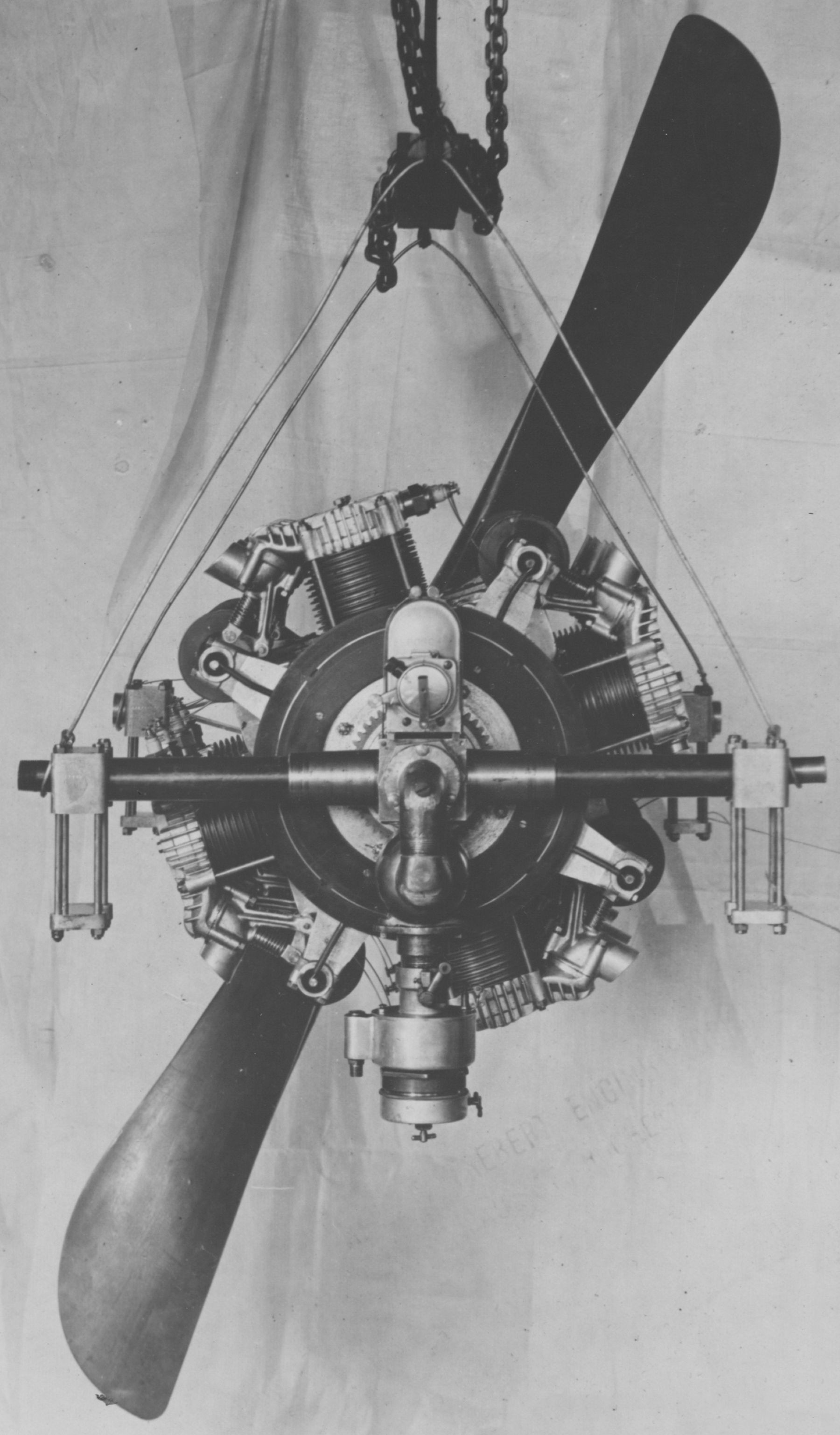
| Trebert Rotary Six (AEE) |
Henry L. F. Trebert of the H.L.F Trebert Motor Works, Rochester, New York, designed several unique aircraft engines beginning with an air-cooled axial rotary six (U.S. Patent 1,215,434) during 1911. This engine concept used a separate crankshaft for each cylinder, that was then bevel-geared to a fixed central gear, causing the engine cylinders to rotate at half the crankshafts' speed. A Panhard carburetor on the anti-propeller end supplied the air/fuel mixture through a rotary valve scheme that also scavenged the exhaust gasses. A Mea magneto at the propeller end furnished ignition to the firing cylinder's spark plug as it passed. With a 3.75" (95.25 mm) bore, 4.25" (107.95 mm) stroke and 281.64 in³ (4.615 l) displacement it produced 60 hp and weighed 230 lb (130 kg). It was 22" (559 mm) long and 15.5" (394 m ) in diameter. The cast-iron cylinders each had a radial extension that communicated with a central chamber that, comprising the rotary valve, provided both inlet and exhaust. Douglas Self provides a clever animation of this engine.
 |
| Trebert V-8 (AEE) |
Next was a water-cooled 90° V-8 with a 4.875" (123.83 mm) bore, 5.000" (127 mm) stroke, and 746.62 in³ (12.235 l) displacement rated 100 hp at 1,200 rpm. Weight was 350 lb (159 kg), length was 48" (1,219 mm), width 26.5" (673 mm), and height 30" (762 mm). The individual cast-iron L-head cylinders with integral water jackets featured a pecular piston-valve design. A port communicating with the cylinder was normally blocked by the valve piston edge, but on the intake stroke the piston was pushed above the port, opening a passage to the intake manifold; on the exhaust stroke, the valve piston descended below the port, thereby communicating with the exhaust stack. The crankshaft was supported in five bearings, and the articulated connecting rods employed H-section shanks. The cast-iron pistons were fitted with three rings. Panhard carburetors supplied the mixture, and Mea magnetos the ignition. A splash lubrication system was used and the valves were lubricated by oil in the fuel.
 |
 |
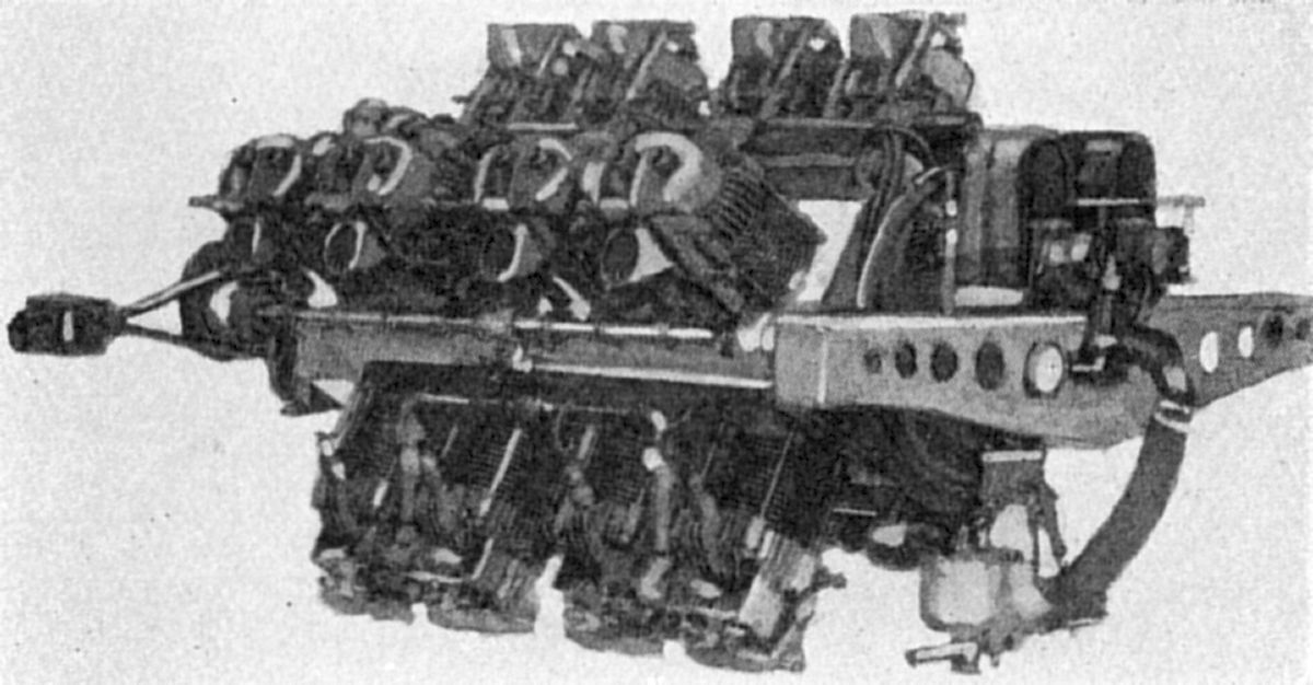
| Trebert X-16 Rotary (A39, NARA) | |
In 1922 Trebert announced an air-cooled X-16 rotary with cylinders arranged in four rows of four each, with a 90° angle between adjacent banks. A Scotch yoke rigidly connected the pistons of opposite cylinders (See U.S. Patent 1,509,885). The Scotch yoke axes were slightly offset from the cylinder axes so the yokes of two cylinder pairs (whose axes were in the same plane), could pass one another. The crankpin bearing was contained in a square box that slid within the two adjacent yokes. Each of the four bearing blocks was 2" (50.8 mm) wide and all four pistons in a row were connected to a single throw of the stationary crankshaft. The Scotch yokes had case-hardened plates working against the hardened bearing surfaces, and it was by this means that the engine rotated, thus leaving the pistons and cylinders free of the usual side-thrust loads. In addition to the cylinder cooling fins a scoop was secured over the exhaust valve to direct air flow upon the valve stem and head as the engine rotated.The valves were held in their seats by centrifugal force and mechanically opened against the entrifugal force. Fuel/air mixture from the carburetor passed through an elbow connected to the hollow crankshaft, into a distributing chamber separate from the crankcase and then through manifolds to the cylinders. The manifolds were of equal length to assure equal distribution. Two two-pole magnetos driven at twice engine speed and delivering four sparks for each revolution of the engine. Sparks were delivered to the cylinders via a distributor located at the engine forward end and consisting of contact brushes and a distributor ring, in which metal segments were embedded in insulating material. Oil was forced into the hollow crankshaft under slight pressure, and passed through radial holes drilled at the centers of the crank-pin bearings. Other parts of the engine were oiled by splash. Trebert claimed the engine had perfect rotating balance, simple design and low weight' it was never produced.
References
Angle, Glenn D, ed. Aerosphere 1939 (New York, New York: Aircraft Publications, 1940).
Anble, Glenn D, ed. Airplane Engine Encyclopedia (Dayton, Ohio: Otterbein Press, 1921).
Image Sources: A39 = Aerosphere 1939; AEE = Airplane Engine Encyclopedia; Flt = Flight Magazine; NARA = U.S. National Archives and Records Administration; UKNA = United Kingdom National Archives; Wiki = Wikimedia Commons (mouse over for details).
Send mail to
![]() with questions or comments about this web site.
with questions or comments about this web site.
![]()