Selected Early Engines
Salmson, Sauda, S.H.K., Siddeley-Deasy, Siemens-Halske,
Smith, S.P.A., Sturtevant, Sunbeam
Compiled by Kimble D. McCutcheon
Published 27 Apr 2023; Revised 29 May 2023
Salmson
In 1890, Emile Jean Jules Salmson (1858 ‑ 1917) opened a small Paris shop that made compressors and centrifugal pumps for rail applications and the French military. In 1896, Swiss engineers Georges Henri Marius Canton and Pierre Georges Unné joined Salmson to build motorized lifts and gasoline engines. In 1908, the trio began developing aircraft engines as the Société des Moteurs Salmson of Billancourt, Seine. A period of intense development ensued, resulting in numerous one-off engines.
Author's Note: Salmson engine designations can be confusing. Not only did Salmson's own designation system change toward the end of WWI to be in compliance with the French standard (number of cylinders, upper-case letter(s) model designation, followed by lower-case model variant), but some designations are reused. Salmson engines built under license outside France often received new designations, and Glenn Angle appears to have made up his own. The author has tried to retain the Salmson designation system where possible.
Water-Cooled Engines [A39, Wikipedia]
|
|
|
| Salmson C (AEE) | Salmson E (A39) | Salmson K (A39) |
The first Salmson engines were opposed-piston barrel test engines. An inlet valve, single spark plug and exhaust valve at the cylinder centers provided inlet, ignition and exhaust; one example of each was built.
The 7-cylinder Salmson A and B (1908 and 1910) had 75 mm (2.953") bores, 125 mm (4.921") strokes, 7.731 l (471.79 in³) displacements and produced 50 hp at 800 rpm.
The 7-cylinder Salmson C and D (1910) were geared 2:1, had 85 mm (2.953") bores, 95 mm (4.921") strokes, 7.547 l (460.55 in³) displacements and produced 60 hp at 1,100 rpm; these featured rotary inlet valves.
The 9-cylinder Salmson E and F (1911) had 110 mm (4.331") bores, 130 mm (5.118") strokes, 22.238 l (1,357.03 in³) displacements and produced 75 hp at 1,200 rpm; these featured cam-actuated poppet valves.
The 7-cylinder Salmson K (1912) had an 85 mm (3.346") bore, 105 mm (4.134") stroke, 8.342 l (509.03 in³) displacement and produced 85 hp at 1200 rpm; automatic inlet valves were used. Unlike earlier geared Salmson barrel engines, the K drove its propeller directly.
Unhappy with its barrel engine output and reliability, Salmson turned its attention to water-cooled radial designs. These all employed the Canon-Unné true-motion connecting rod scheme, a patent [GB 190,927,672] for which Canton and Unné applied on 15 Dec 1908. These engines also included patented "hairpin" valve springs [GB 191,109,454A].
 |
 |
 |
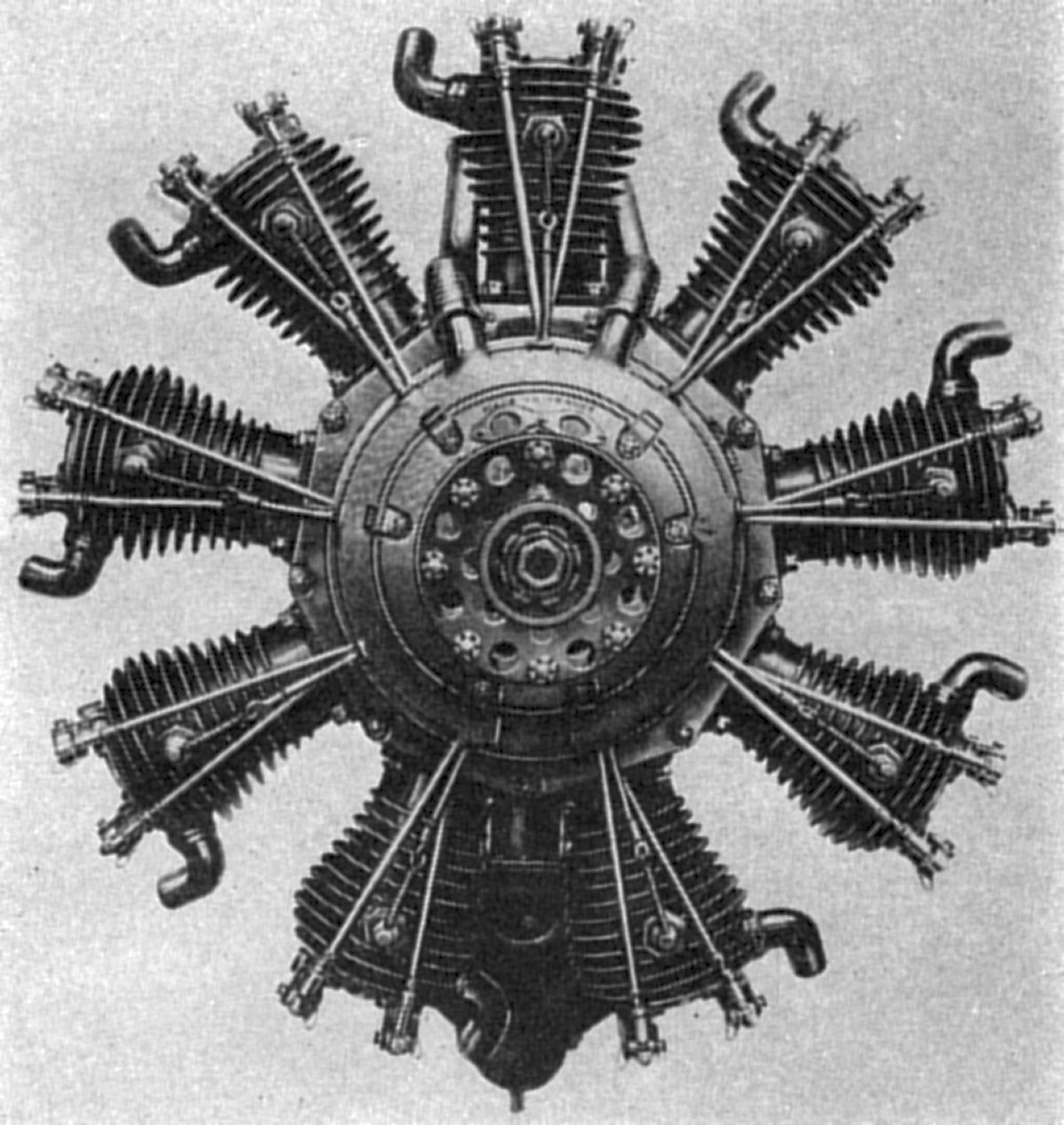
| A7 (NARA) | A9 (NARA) | AZ9 (A39) |
The A7 (1911), a radial 7 with a 120 mm (4.724") bore, 140 mm (5.512") stroke and 11.084 l (675.75 in³) displacement produced 80 – 100 hp. Five test engines were built.
The A9 (1912), a radial 9, was Salmson’s first “production” engine. With a 122 mm (4.803") bore, 140 mm (5.512") stroke and 14.729 l (898.83 in³) displacement, it produced 110 – 130 hp; certified to 47 hours running by 1914, 30 were built.
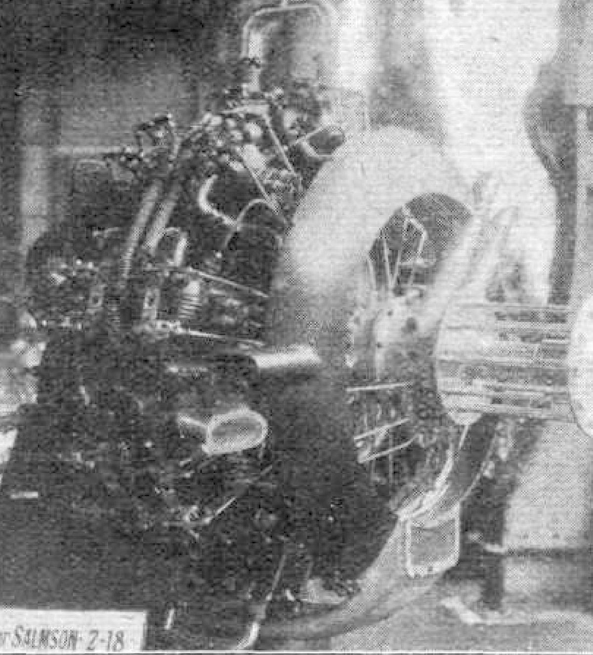
The 2A9 (1913) was a 2-row radial 18 with a 122 mm (4.803") bore, 140 mm (5.512") stroke and 29.458 l (1797.67 in³) displacement that produced 313 hp at 1,500 rpm; 1 test engine was built.
The A2C, with the same characteristics as the A9, was capable of delivering power from either end. Rated 260 hp at 1,350 rpm, 300 were constructed during 1916.
The AZ9 was a radial 9 with a 140 mm (5.512") bore, 170 mm (6.693") stroke and 23.552 l (1,437.26 in³) displacement that was rated 300 hp at 1,500 rpm. While this engine had the same dimensions as the A9, it followed more closely the design of the Z types. The cylinders, however, were bolted to the crankcase and had four valves. A plain master rod bearing was used. Several AZ9 engines were built from 1920 to 1923, some with 3:2 propeller reduction gearing.
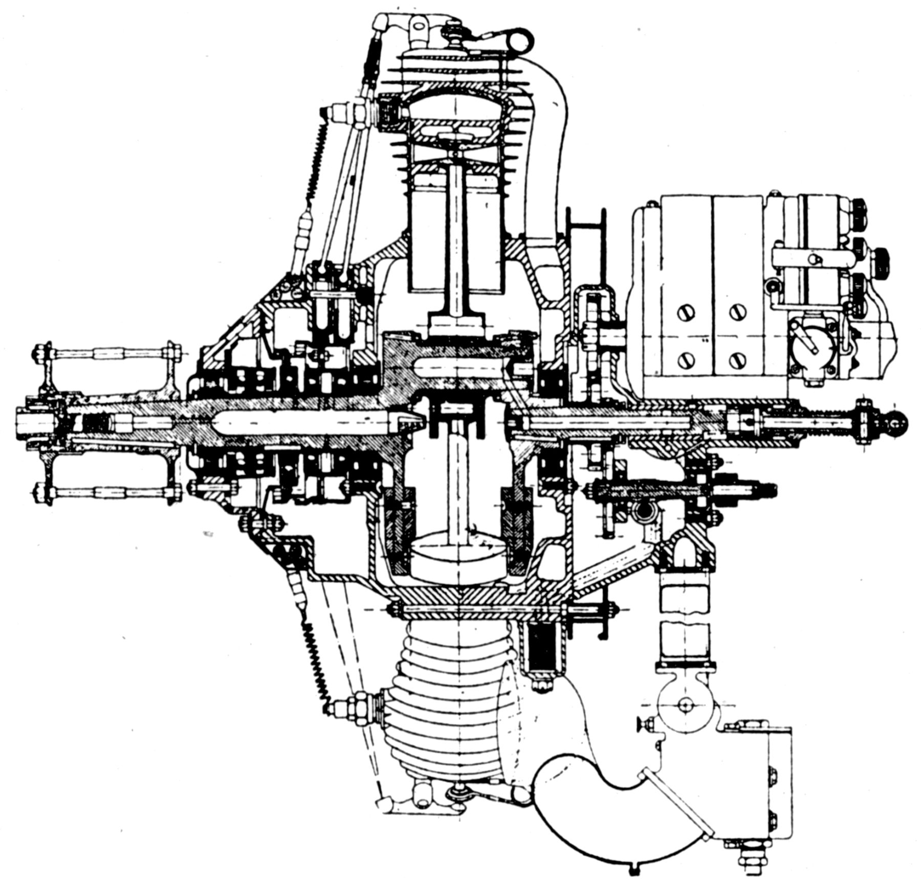
 |
| Salmson B (AEE) |
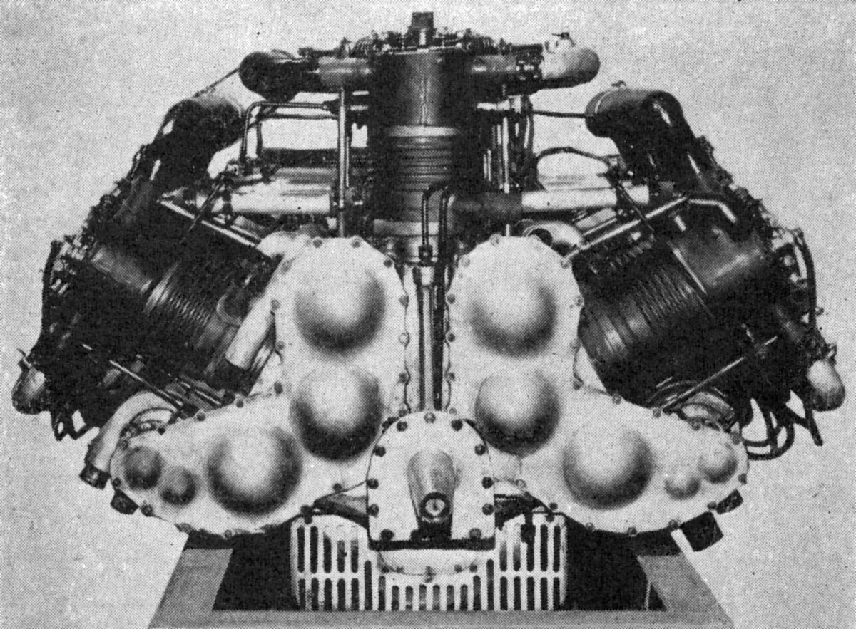
The B (1913 – 1914) was a radial 9 with its cylinders in the horizontal plane and the propeller driven at a 9:5 ratio through bevel gears. Used in dirigibles and seaplanes, it had a 110 mm (4.331") bore, 150 mm (5.906") stroke and 12.829 l (782.90 in³) displacement.
The C9 (1912), a horizontal radial 9 with a 150 mm (5.906") bore, 180 mm (7.087") stroke and 28.628 l (1746.97 in³) displacement, it produced 300 hp; 1 test engine was built.
The D9 was a horizontal radial nine with a 150 mm (5.906") bore, 200 mm (7.874") stroke and 31.809 l (1,941.08 in³) displacement that was rated at 200 hp.
The OD9 was a horizontal radial nine with a 150 mm (5.906") bore, 210 mm (8.268") stroke and 33.399 l (2,038.14 in³) displacement that was rated 300 hp at 1,200 rpm and weighed 449 kg (990 lb).
The 2D9 was a two-row radial 18 using D9 components that displaced 66.798 l (4,076.27 in³), was rated 600 hp at 1,200 rpm, and weighed 1,115.84 kg (2,460 lb).
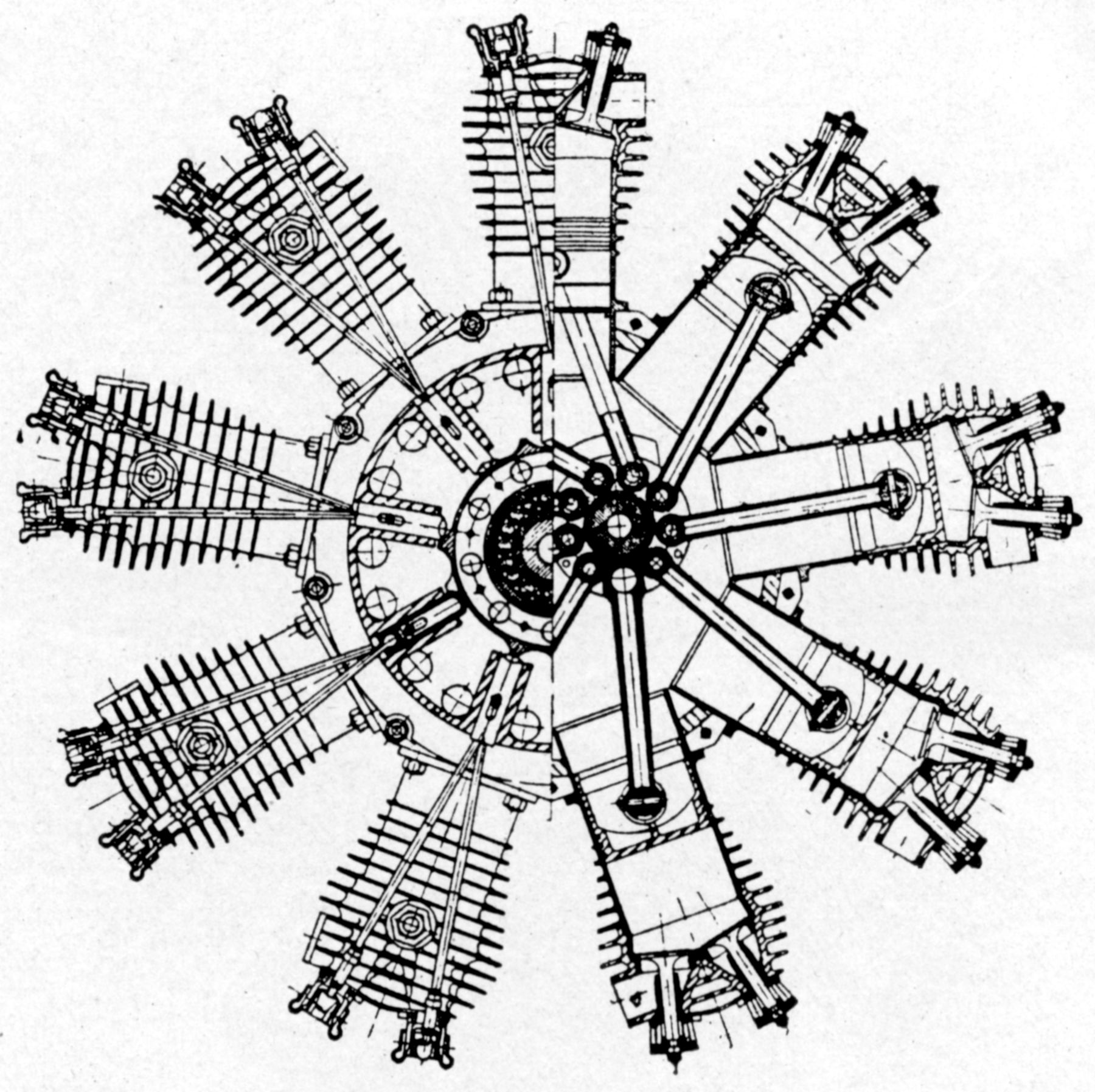
 |
| B9 (Wiki) |
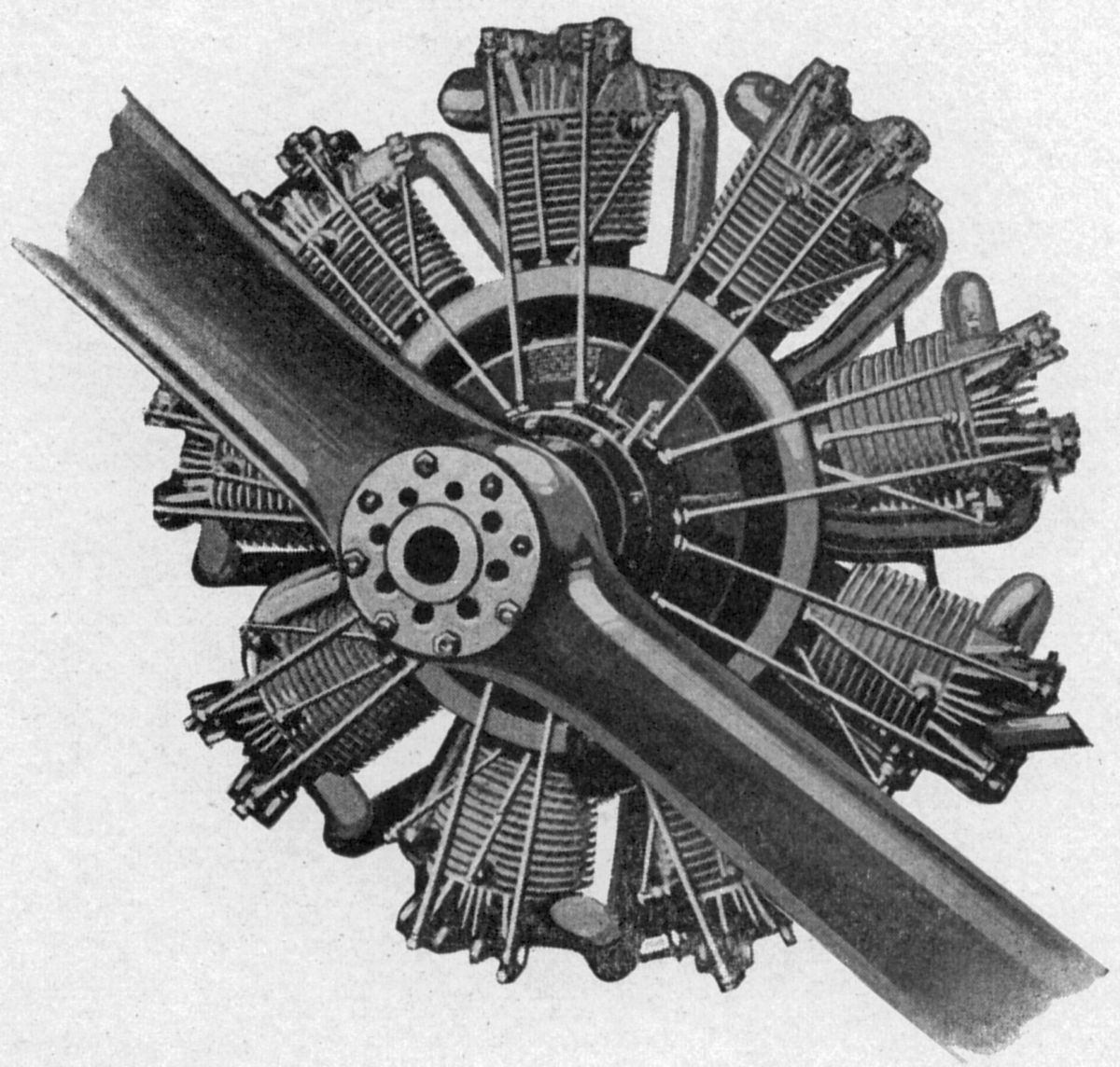
The B9 (1913) was a conventionally-mounted radial 9 with a 122 mm (4.803") bore, 140 mm (5.512") stroke and 14.729 l (898.83 in³) displacement that produced 140 hp at 1,250 rpm. Salmson built 300 and 106 were built in Great Britain.
The G9 was a conventionally-mounted radial 9 with steel cylinders and brazed-in-place spun-copper water jackets. The cast-iron pistons were fitted with three rings, and the two-piece aluminum alloy crankcase was joined in the cylinder plane, securely clamping the cylinders in place [US 1,099,424A]. The two crankshaft pieces were joined by a short taper on the crankpin held in the rear crank web by a key and nut. It was mounted on ball bearings, as were the other rotating parts. The H-shank connecting rods were hinged to a non-oscillating carrier that produced a circular path for each big end. The valves were vertically in the cylinder heads and operated via tappets, push rods, and rockers. Separate cams for each valve pair were keyed to a sleeve driven by a gear train at 0.5 engine speed. The roller cam followers were at the outer ends of centrally-pivoted levers that successively lifted each valve tappet as the cam rotated, causing the inlet and exhaust valve opening periods to be equal.
The H9 was a 7:5-geared radial 9 similar to the G9. It had a 120 mm (4.724") bore, 140 mm (4.512") stroke and 14.250 l (869.60 in³) displacement.
 |
 |
 |
| M7 (NARA) | M9 (A39) | |
The M7 (1913), a radial 7 with a 122 mm (4.803") bore, 140 mm (5.512") stroke and 11.456 l (699.09 in³) displacement, produced 100 – 115 hp. Fuel consumption was 0.53 lb/hp/hr and it weighed 170 kg (375 lb); 50 test engines were built.
The OM7 was similar to the M7, but with a 160 mm (6.299") stroke and 12.667 l (772.98 in³) displacement.
The 2M7 (1913) was 2-row 6-stroke/cycle radial 14 with M7 cylinders, a 122 mm (4.803") bore, 140 mm (5.512") stroke and 22.912 l (1,398.18 in³) displacement. It produced 200 hp at 1,300 rpm. Fuel and oil consumptions were 0.53 and 0.07 lb/hp/hr, it weighed 424 kg (935 lb) and was 1,049 mm (41.3") in diameter. The 2M7 had a single-throw crankshaft and special gearing that rotated the cams at one-third crankshaft speed. Salmson built 15, and 300 were built in Great Britain by the Dudbridge Iron Works Ltd, Stroud, Gloucestershire.
The M9 (1914) was a radial 9 using M7 cylinders with a 122 mm (4.803") bore, 140 mm (5.512") stroke and 14.729 l (898.83 in³) displacement that produced 120 hp – 130 hp at 1,300 rpm. Fuel and oil consumptions were 0.61 and 0.059 lb/hp/hr, and it weighed 211 kg (465 lb), including radiator; 500 were built in France.
 |
| P9 (A39) |
The P9 (1915) was a radial 9 with a 122 mm (4.803") bore, 140 mm (5.512") stroke and 14.729 l (898.83 in³) displacement that produced 150 hp at 1,300 rpm; 300 were built in France and 300 in Russia
The R9 (1915) was a radial 9 with a 125 mm (4.921") bore, 140 mm (5.512") stroke and 15.463 l (943.58 in³) that produced 150 hp – 160 hp at 1,300 rpm. Fuel consumption was 0.5 lb/hp/hr and it weighed, complete with radiator, 319 kg (704 lb). France built 50 and Russia built 300.
The X9 or 9Rb was similar to the P9 and R9, but produced 160 hp at 1,350 rpm. During 1916 and 1917, more than 300 X9 engines were built and installed in Russian Air Service airplanes.
The A9 was a radial 9 with a 140 mm (5.512") bore, 170 mm (6.693") stroke and 23.553 l (1437.26 in³) displacement that was rated 230 hp at 1,280 rpm. Fuel consumption was 0.5 lb/hp/hr and weight, including radiator, was 439 kg (968 lb). Diameter was 1,181 mm (46.5"). During 1916, 350 A9 engines were constructed.
 |
 |
 |
 |
| Early 9Z (NARA) |
Later 9Z (Wiki) |
Later 9Z (A39) |
|
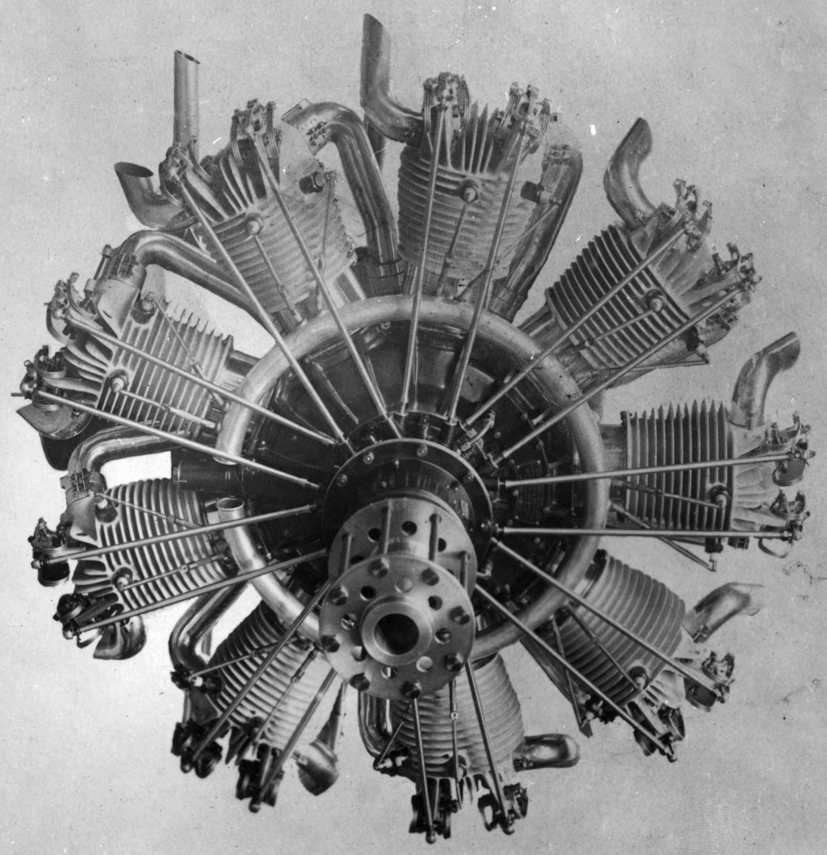
The 9Z (also Z9 and Z-9, 1917) was a radial 9 series. The early engines had a 125 mm (4.921") bore, 165 mm (6.496") stroke and 18.224 l (1,112.08 in³) displacement and were rated 230 hp at 1,500 rpm. Later versions, with 125 mm (4.921") bores, 170 mm (6.693") strokes, 18.776 l (1,145.78 in³) displacements and 5.4:1 compression ratios, produced 250 hp at 1,550 rpm. Fuel and oil consumption was 0.495 and 0.077 lb/hp/hr, and weight was 214.5 kg (473 lb). France built 3,000 and Great Britain built 56. The 9Za, 9Zm and 9Zc were all variants.
Early 9z engines were the last Salmson radials to employ the Canton-Unné true-motion connecting rod scheme; later versions had an H-section master rod with a solid big end running on two ball bearings and located in a lower cylinder. The link rods had tubular shanks that were hinged via knuckle pins in the master rod big ends. The two-piece single-throw crankshaft was joined by a taper, key and nut. The aluminum alloy pistons were fitted with four top compression rings and one lower oil-scraper ring. The steel cylinders had welded-on sheet-steel water jackets and lower flanges that were captured between the two crankcase sections. Exterior wedging rings pulled the cylinder tightly against the crankcase. The inlet and exhaust valves were inclined slightly in the cylinder head and operated via push rods and rocker arms by three inlet and three exhaust cams turning in the crankshaft direction 0.25 crankshaft speed. Inlet valves opened at top center and closed 55° late; exhaust valves opened 65° early and closed at top center. Two nine-cylinder magnetos supplied dual ignition, and Claudel or Zenith duplex carburetors furnished the mixture. Oil was circulated by two oscillating plunger pumps; the small plunger forced oil to the bearings under pressure and the large one was a scavenge pump.
 |
| 18Z (Wiki) |
The 18Z (1918) was a 2-row inline radial 18 with a 125 mm (4.921") bore, 170 mm (6.693") stroke, 37.552 l (2,291.55 in³) displacement and 5.4:1 compression ratio that produced 500 hp at 1,600 rpm and 560 hp at 1,700 rpm. Fuel and oil consumptions were 0.485 and 0.086 lb/hp/hr. Weight was 453.6 kg (1,000 lb) and diameter was 1,003 mm (39.5"). Between 1918 and 1919, 25 18Z engines were built.
 |
| C12 (A39) |
The C12 was an experimental W-12, believed to be the first such type ever built. With a 140 mm (5.512") bore, 180mm (7.087") stroke and 33.251 l (2,029.08 in³) displacement, it was rated 380 hp at 1,330 rpm.
The 9CM was introduced in 1923 to replace the 9Z. With a 125 mm (4.921") bore, 170 mm (6.693") stroke and 18.776 l (1,145.78 in³) displacement, it delivered 260 hp at 1,650 rpm. Except for the cylinders, 9CM parts were mostly interchangeable with 9Z parts. The steel cylinders had welded-in-place sheet-metal water jackets.
The 18CM was a double 9CM version that was developed about the same time. It produced 500 hp at 1,650 rpm and weighed 459 kg (1,012 lb). The paired cylinders were mounted in tandem on a common bracket.
The 18CMb was an improved 18CM engine introduced in January 1927. While many parts were interchangeable with the 18CM, it was built with special attention to reliability and was used extensively for long distance flights. With a 5.4:1 compression ratio, it produced 520 hp at 1,650 rpm and 565 hp at 1,740 rpm and weighed 459 kg (1,012 lb).
Air-Cooled Engines [A39, Wikipedia]
 |
 |
 |
| Air-Cooled 9Z (A39) |
9Ab (A39) |
18Ab (A39) |
During 1917, Salmson built an experimental air-cooled 9Z that produced 230 hp at 1,500 rpm and weighed 226.8 kg (500 lb). The aluminum alloy cylinders had screwed-in steel liners. Push rods and rocker arms operated the valves. Salmson also experimented with an 11-cylinder air-cooled radial with a 105 mm (4.134") bore, 160 mm (6.299") stroke and 15,240 l (929.99in³) displacement that was rated at 280 hp, weighed 170 kg (375 lb) and was 1,499 mm (59") in diameter.
The 9Ab, a later and refined air-cooled 9Z, was introduced in August 1924. With a 125 mm (4.921") bore, 170 mm (6.693") stroke, 18.776 l (1,145.78 in³) displacement and 5.4:1 compression ratio, it was rated 230 hp at 1,700 rpm. Fuel and oil consumptions were 0.539 and 0.044 lb/hp/hr , dry weight was 264.4 kg (583 lb), the diameter was 1,000 mm (39.37") and the length 1,180 mm (46.45"). The steel cylinders were fitted with shrunk-on aluminum cooling fins. The articulated connecting rod had a white-metal lined bearing. The slightly inclined valves were operated by push rods and roller tappets from cam rings in the nose case. An inlet tube connected each cylinder to a cored passage at the crankcase rear. Two Salmson GG9 type 25 magnetos supplied dual ignition. An optional circular exhaust manifold was attached to the engine front.
The 18Ab, a two-row inline radial 18 using 9AB cylinders, had a 125 mm (4.921") bore, 180 mm (7.087") stroke, 39.761 l (2,426.35 in³) displacement and 5.2:1 compression ratio. Producing 500 hp at 1,700 rpm and 565 hp at 1,780 rpm, it weighed 449 kg (990 lb), was 1,200 (47.24") in diameter and 1,370 mm (53.93") long. The cylinders were arranged in tandem, mounted in pairs on a common bracket attached to the crankcase by studs. The crankshaft had one throw with the master connecting rods placed side-by-side on the crankpin. A common circular intake manifold cored in the crankcase rear distributed the fuel/air mixture to the cylinders through heated induction pipes. Two rear-mounted double carburetors were fitted with altitude control. Compressed air acting on the nine rear cylinders started the engine. Two Salmson 4G 18 magnetos furnished dual ignition. Gear-type pumps provided dry-sump lubrication.
The 18Abs was practically identical to the 18Ab except that it had a two-speed centrifugal supercharger that ran at 10.6 times crankshaft speed in high gear. It produced 600 hp at 1,700 rpm for takeoff and a 650 hp at 1,880 rpm maximum. It could deliver 500 hp up to 3,000 m (9,843 ft). Dry weight was 464 kg (1,023 lb).
 |
| 9Nc (A39) |
The 9Na was a radial 9 with a of 140 mm (5.512") bore, 160 mm (6.299") stroke, 22.167 l (1,352.72 in³) displacement and 5.1:1 compression ratio that was rated 300 hp at 1,800 rpm and weighed 291.4 kg (642.5 lb).
The 9Nas, derived front the 9NA, featured a two-speed centrifugal supercharger and 5.0:1 compression ratio. At sea level and in low blower (8.0:1) it produced 450 hp at 1,980 rpm. In high blower (11.0:1) it could maintain 300 hp up to 3,000 m (9,843 ft). Dry weight was 314.3 kg (693 lb).
The 9Nc was a radial 9 with a , 9.896 l (603.89 in³) displacement and 5.0:1 compression ratio rated 135 hp at 1,800 rpm and 156 hp at 1,900 rpm. Its dry weight was 154 kg (339 lb) its diameter 935 mm (36.8") and its length 768 mm (30.23").
The 9Nct was a 9NC fitted with a centrifugal supercharger that could maintain 135 hp at 1,800 rpm up to 2000 m (6,562 ft). Sea level output was 160 hp at 1,800 rpm and 170 hp at 1,980 rpm. Compression ratio was 5.0:1, the supercharger impeller turned at 11 times crankshaft speed and dry weight was 164.7 kg (363 lb).
Starting in June 1924, Salmson introduced an engine series based on cylinders with 100 mm (3.937") bores and 130 mm (5.118") strokes.
 |
 |
| 7Ac (A39) | 9Ac (A39) |
The 9Ac (1924) was a radial 9 displacing 9.189 l (560.76 in³) and rated 120 hp at 1,800 rpm. Fuel and oil consumptions were 0.539 and 0.044 lb/hp/hr. Its diameter was 950 mm (37.4"), its length 899 mm (35.4") and its weight 169.6 kg (374 lb).
The 7Ac (1927) was a radial 7 displacing 7.147 l (436.14 in³) and rated 95 hp at 1,800 rpm. Its diameter was 940 mm (37.0"), its length 820 mm (32.28") and its weight 129.7 kg (286 lb).
The 5Ac was a radial 5 displacing 5.105 l (311.53 in³) and rated 60 hp at 1,800 rpm. Its diameter was 940 mm (37.0"), its length 820 mm (32.28") and its weight 109.8 kg (242 lb).
The 3Ad, a radial 3 introduced in June 1923, had a 70 mm (2.756") bore, 86 mm (3.386") stroke, 0.993 l (60.59 in³) displacement and 5.6:1 compression ratio. It produced 12 hp at 1,800 rpm and 15 hp at 2,400 rpm. Its diameter was 630 mm (24.8"), its length 570 mm (22.44") and its weight 34 kg (75 lb). A single Salmson magneto provided single ignition.
The 6Ad, introduced about the same time as the 9Ad, was a 9Ad minus three cylinders and associated parts. The vertical top cylinder and the two cylinders 120° to either side were omitted, but the cycle regularity was preserved. The result was a 25 hp engine that met the limited demand without the need to design and build an entirely new type. The 6Ad displaced 1.986 l (121.18 in³), produced 25 hp at 1,900 rpm and weighed 60 kg (132 lb). Its diameter was 630 mm (24.8") and its length was 690 mm (27.16").
 |
 |
 |
 |
| 3Ad (Wiki) | 9Ad (A39) | ||
The 9Ad, introduced in June 1925, was a radial 9 displacing 2.979 l (181.77 in³). With a 5.6:1 compression ratio, it was rated 40 hp at 2,000 rpm and weighed 68 kg (150 lb). Its diameter was 630 mm (24.8") and its length was 690 mm (27.16"). The cast iron cylinders had integral cooling fins. The inlet ports faced aft and were connected with a pipe from the circular inlet passage cored in the crankcase. The exhaust ports pointed to the cylinder side. The inclined valves were actuated by push rods and rocker arms by a double cam ring in the crankcase nose section. The master rod was located in a lower cylinder and was fitted with a plain bearing. The link rods had tubular shanks The two-piece crankshaft was joined by a taper, key and nut at the crankpin rear. A joint in the cylinder plane along with a bolt between each cylinder pair held the two main aluminum alloy crankcase sections together. The 9Ad engines were used extensively in light airplanes throughout Europe, and several were sold by the Aeromarine-Klem Corporation of Keyport, New Jersey.
Salmson continued making aircraft engines and introduced many new types until 1951. In 1960, the company returned to making pumps and was eventually absorbed by a conglomerate.
Sauda
 |
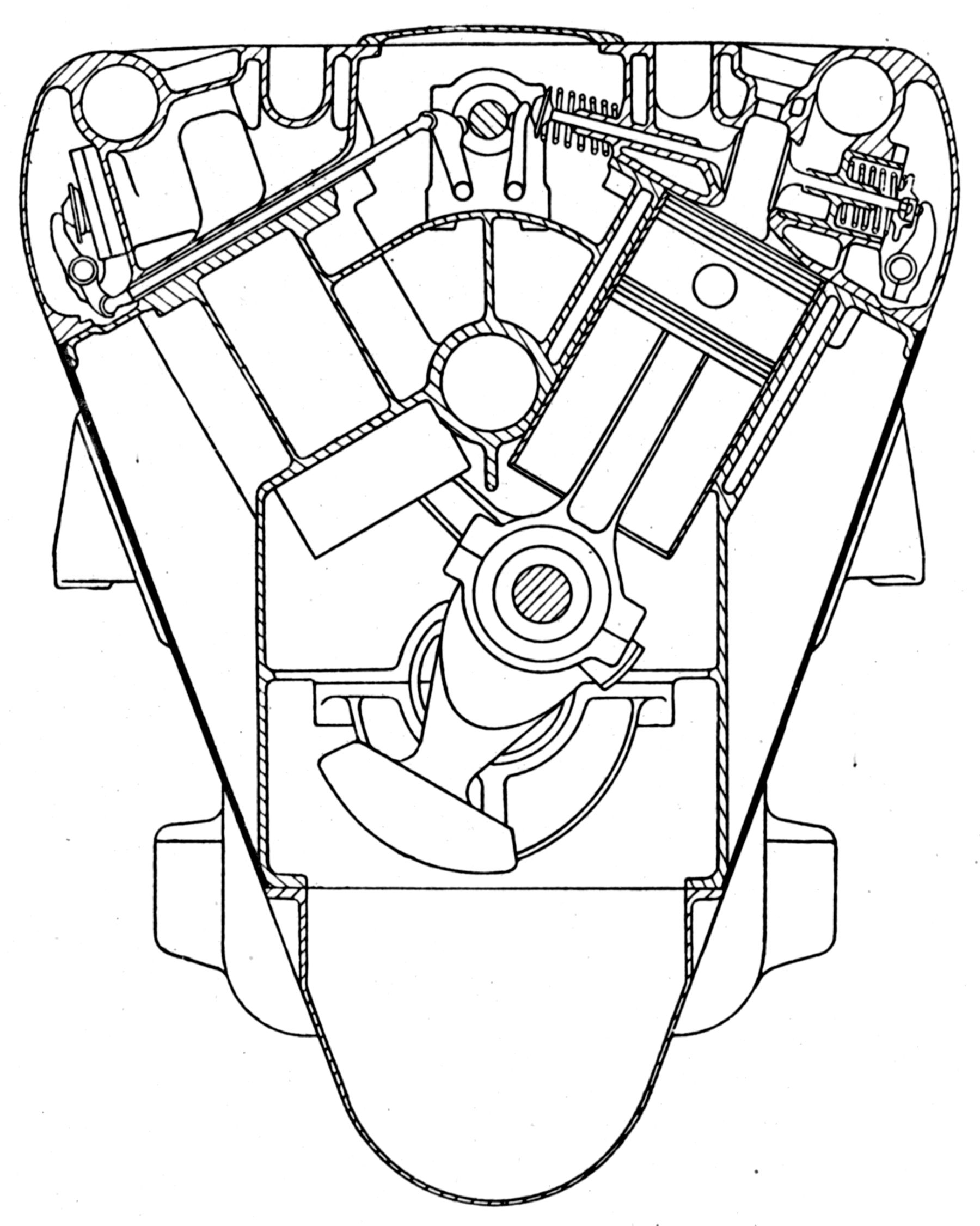 |
| Sauda Cappa 18 (A39) | |
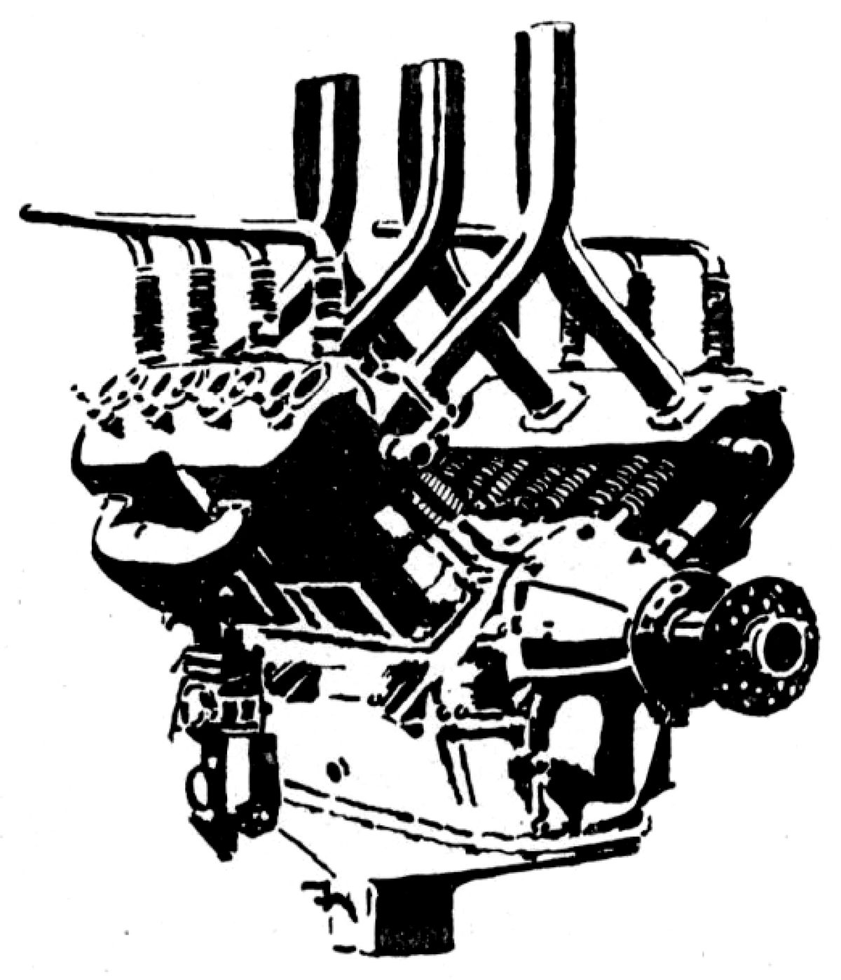
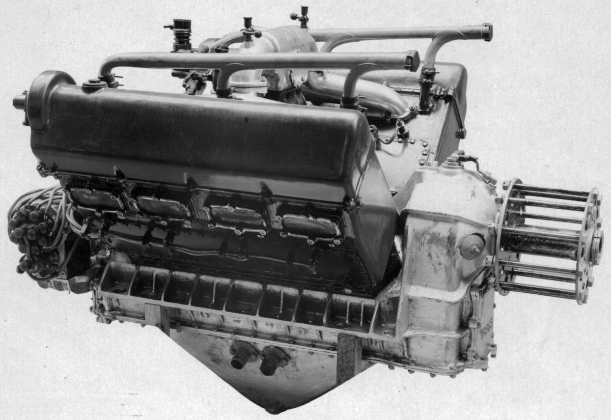
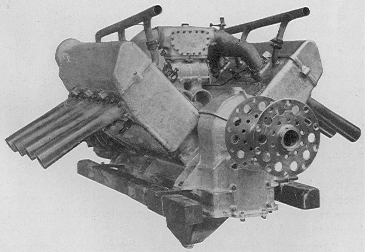
M. L'ing. Sauda of Italy exhibited the Cappa 18 engine at the 1926 Paris Show. Incorporating several unusual combustion chamber and valve gear design features, this engine presented an exceptionally clean exterior.
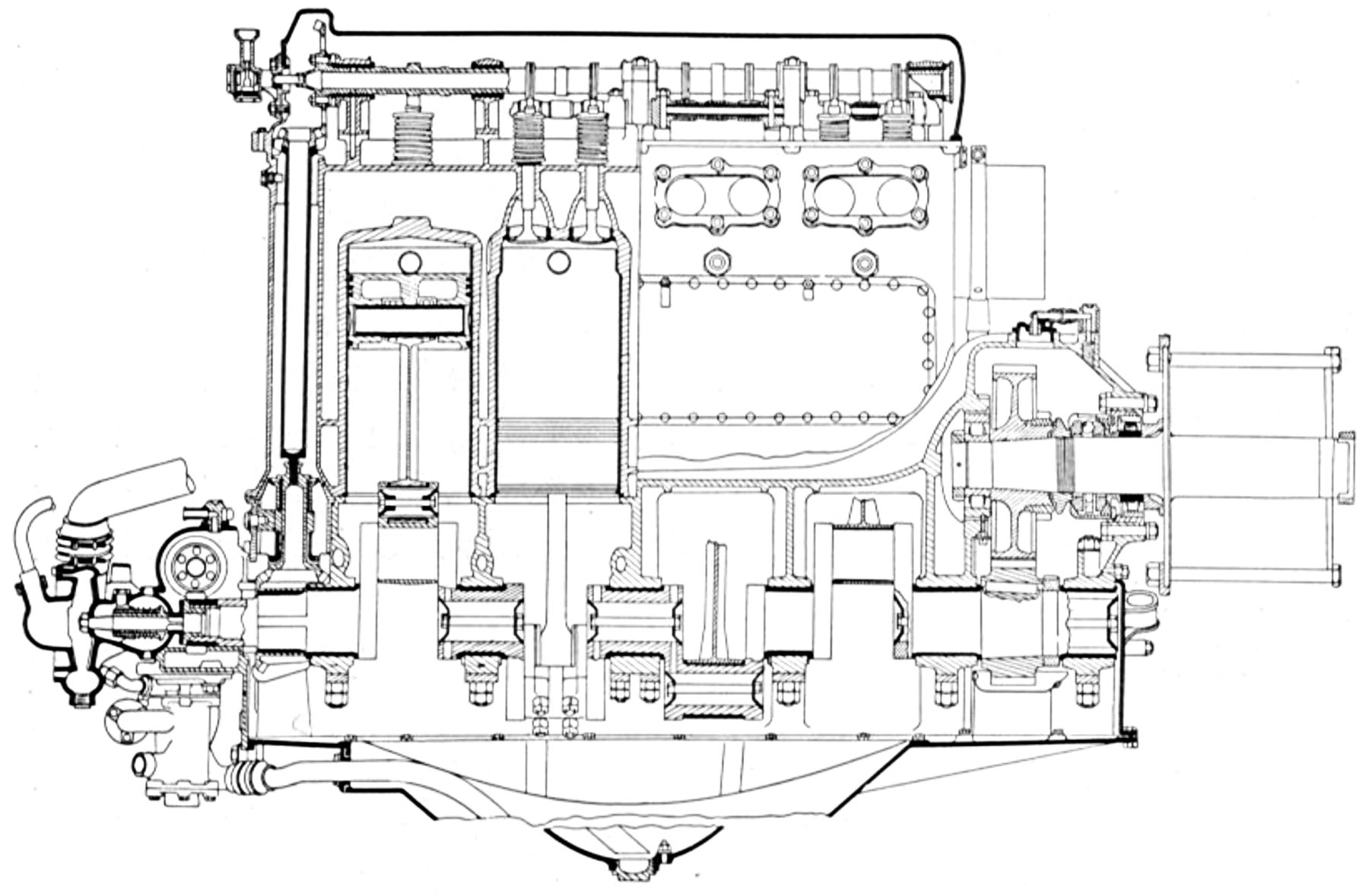
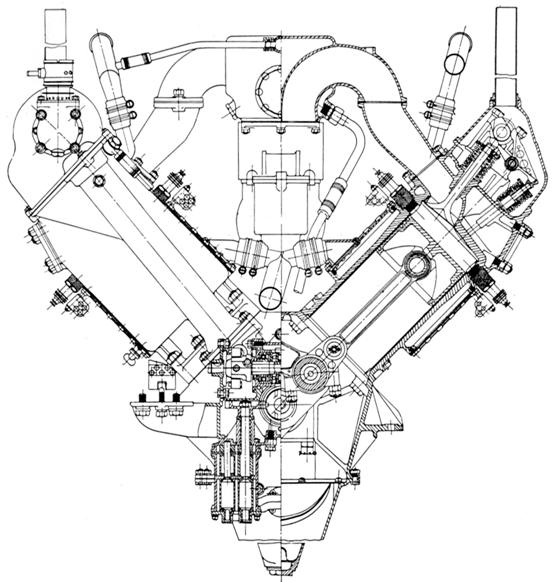
The Cappa 18 was a 1.4:1-geared water-cooled 60° V-12 with a 120 mm (4.724"), 135 mm (5.315") stroke, 18.322 l (1,118.06 in³) displacement and 6.0:1 compression ratio that produced 400 hp at 2,300 rpm. Fuel consumption was 0.47 lb/hp/hr and dry weight was 380 kg (838 lb). A single aluminum alloy casting comprised the cylinders and crankcase, which extended well below the crankshaft centerline. Wet cylinder liners were case-hardened seamless steel tubes pressed into the block. The semi-slipper aluminum alloy pistons had three compression rings above the full-floating piston pin and a wide ring below. Sturdy blade-and-fork connecting rods featured the fork rod running upon a bronze shell on either side of the blade big end. The big ends were split and a bridge connected the fork cap to ensure rigidity. The blade big end enclosed roller bearings contained in a split cage borne upon the outer race to reduce centrifugal loading. The crankshaft may have run on roller bearings although the longitudinal section drawing does not show this. Two symmetrical forgings comprised the crankshaft, and the end flanges were bolted to the reduction gear pinion in the engine center. The reduction gears had helical teeth with a 20° pressure angle. The aft propeller shaft end and the driven gear were supported on roller bearings, and a spline joint drove the propeller shaft, which was supported in front by a ball thrust bearing. The crankshaft pinion also drove, through an idler, the pump spindle located in the sump. The oil and water pumps were combined in a single unit. The camshaft was driven by a spur gear train along side the main reduction gear, and the supercharger was driven by a quill shaft splined to the propeller shaft aft end. The auxiliaries were driven by a spur gear train at the engine center. Shafts at right angles to the camshaft, driven through bevel gears, drove the two-coil distributors.
Each cylinder bank had a single cast aluminum alloy head that included the valve ports and water passages. The four valves in each cylinder were positioned so their stem axes were perpendicular to the camshaft axis and nearly perpendicular to the cylinder axes. The exhaust valve stems pointed toward the central camshaft and the outer intake valves operated through push rods and rocker arms. Cored passage extending through the cylinder head from the Vee interior provided the mixture Each camshaft had a fore and aft section, each driven by a gear at the engine center. Each exhaust cam actuated the opposite valve pairs of corresponding cylinders. Only one inlet cam was required for both valves of corresponding cylinders. Consequently, there were 18 cams in all. The exhaust valves used bronze seats and service required removal of the opposite intake valve cage. Ignition was provided by two coil systems, and the distributors were enclosed by the metal covers that also enclosed the spark plugs and inlet valve operating mechanism. The camshaft and the tappets operating the exhaust valves were readily accessible upon the removal of a top cover plate.
The engine was available with an optional centrifugal supercharger mounted at the engine rear and driven by an internal spur gear on the main reduction gear through a friction clutch. Two ratios were available ‑ one that produced 12,000 rpm and was intended for maximum power at low altitudes, and another that produced 20,000 rpm, which maintained full power up to 5,182 m (17,000 ft). Two floatless Cappa-Astra carburetors attached to the supercharger inlet when the supercharger was used. Otherwise, four carburetors were attached to the cylinder block outside. An electric generator drive was provided at the crankshaft front, and at the rear were five drives for tachometer, gun synchronizer, etc. Starting was accomplished by means of a crank that operated on the pump shaft through a reduction gear.
The engine was supported by aluminum castings bolted to the block sides against rubber pads, which were supposed to dampen vibration. The overall dimensions were comparatively small for an engine of this output, and the clean exterior permitted the engine to be mounted without a cowling.
S.H.K.
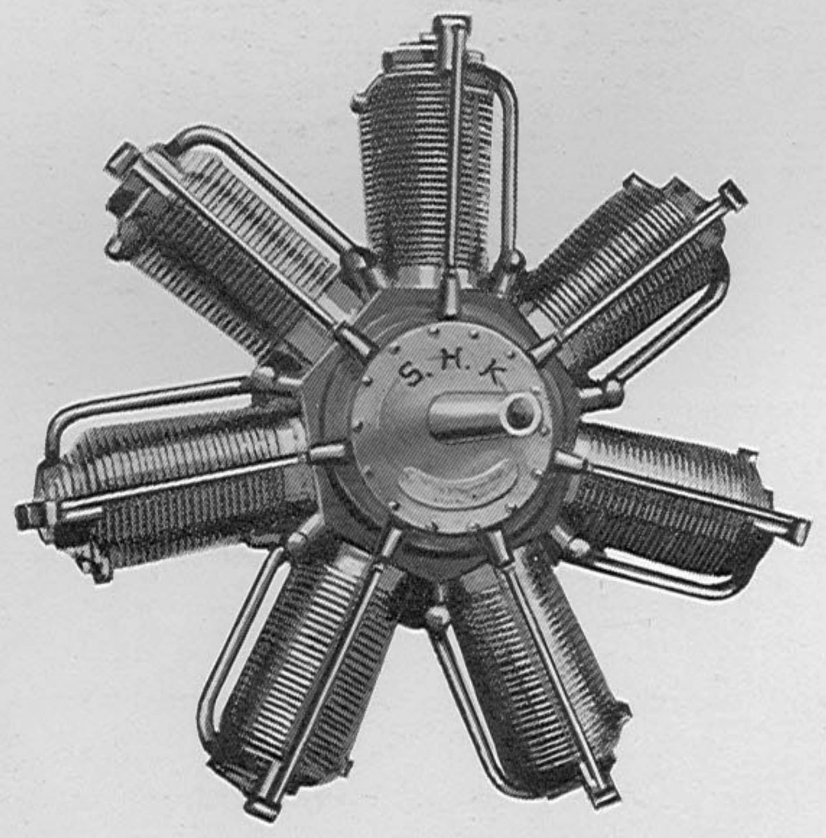 |
| S.H.K. 70 hp (AEE) |
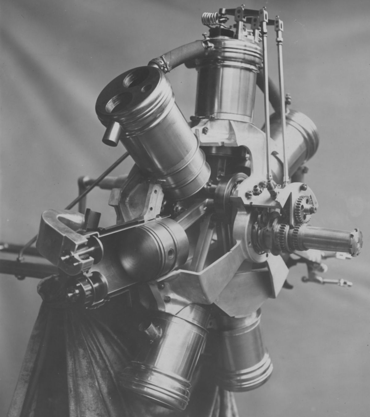
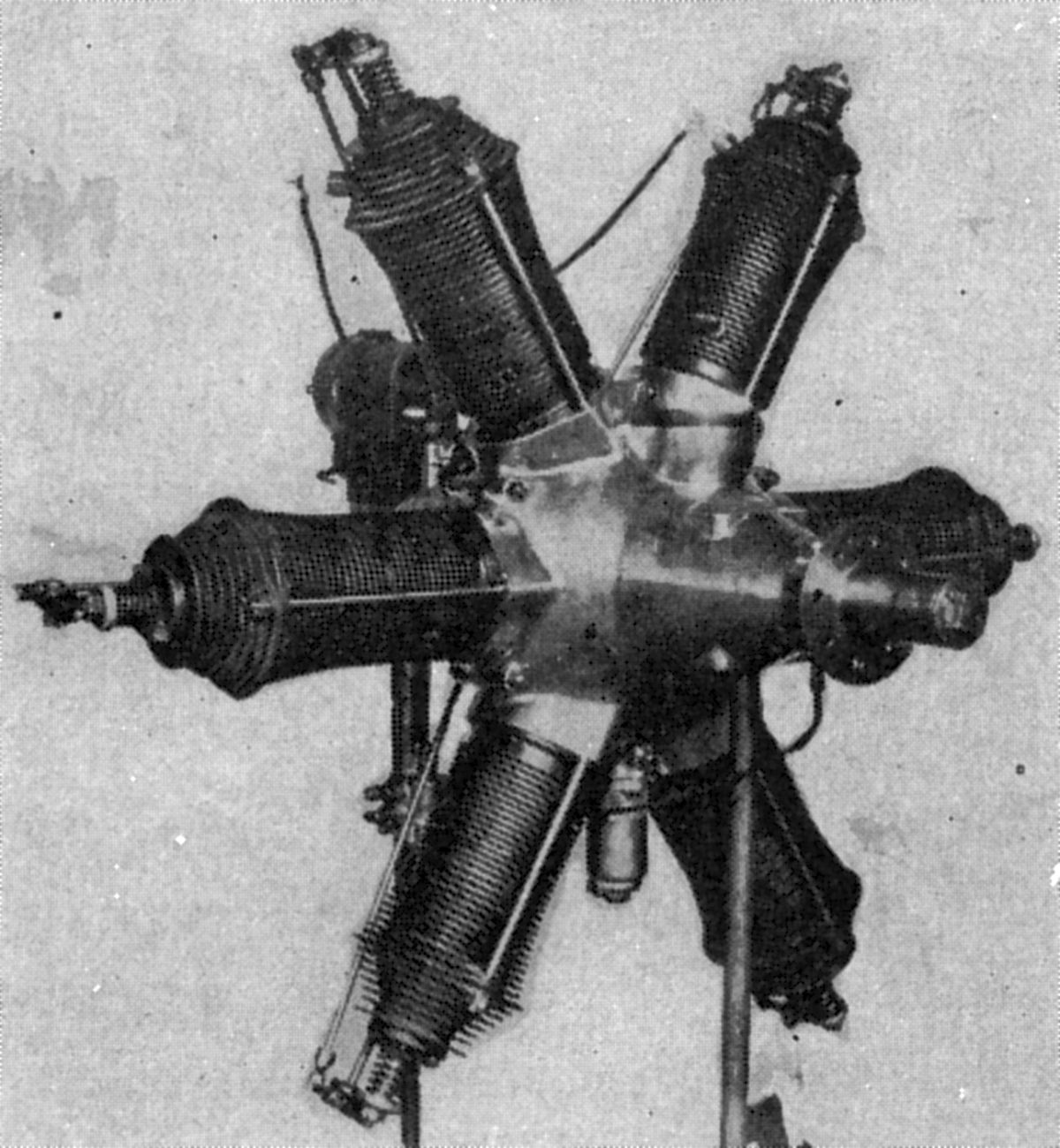
The French S. H. K. Company exhibited four air-cooled rotary engines at the 1913 Paris Show. The steel cylinders had circumferential cooling fins and were secured to the steel crankcase by a gland nut that screwed into the case, capturing a flange at the cylinder base. The gland nut was secured by a locking ring. The connecting rods contacted the crankpin by feet to which bronze shoes were riveted. Two U-shaped rings encircled the lateral crankshaft extensions and secured them in position. No piston rings were used, as gas tightness was meant to be enforced by three shallow grooves around the piston. The two-piece crankshaft was fitted with ball bearings to support the rotating crankcase and cylinder mass. Concentric valves were operated by a single push rod. A plunger pump delivered oil under pressure to the crankpin, cams, and gears. A high-tension magneto furnished ignition.
Siddeley-Deasy [A39, Wikipedia]
Henry Hugh Peter Deasy (29 Jun 1866 ‑ 24 Jan 1947) was an Irish Army officer, adventurer, automobile record setter, writer and founder of several manufacturing concerns. In 1906, he formed the Deasy Motor Car Manufacturing Co., which took over the factory formerly used by the Iden Car Co. at Parkside, Coventry. On 9 Mar 1908, Deasy resigned after adispute with car designer and chief engineer Edmund W Lewis. In 1910 the Deasy directors appointed J.D. Siddeley managing director; Siddeley had previously managed Wolseley. Pleased with his success, the shareholders changed the company name to Siddeley-Deasy Motor Car Company Limited on 7 Nov 1912.
During WWI Siddeley-Deasy expanded to 5,000 workers producing ambulances and aircraft engines. After WWI conditions for manufacturers were difficult, and in 1919 Siddeley merged with Sir W.G.Armstrong Whitworth & Co Limited Motor Car Department. Armstrong-Whitworthhad been a supplier of Siddeley-Deasy engine castings. Armstrong Whitworth acquired a controlling interest in The Siddeley-Deasy Motor Car Company Limited and changed its name to The Armstrong Siddeley Company Limited. Armstrong Siddeley produced radial aircraft engines through WWII, turbojets and rocket engines thereafter.
 |
 |
 |
 |
|
| (Wiki) | (AEE) | (Wiki) | (AEE) | (AEE) |
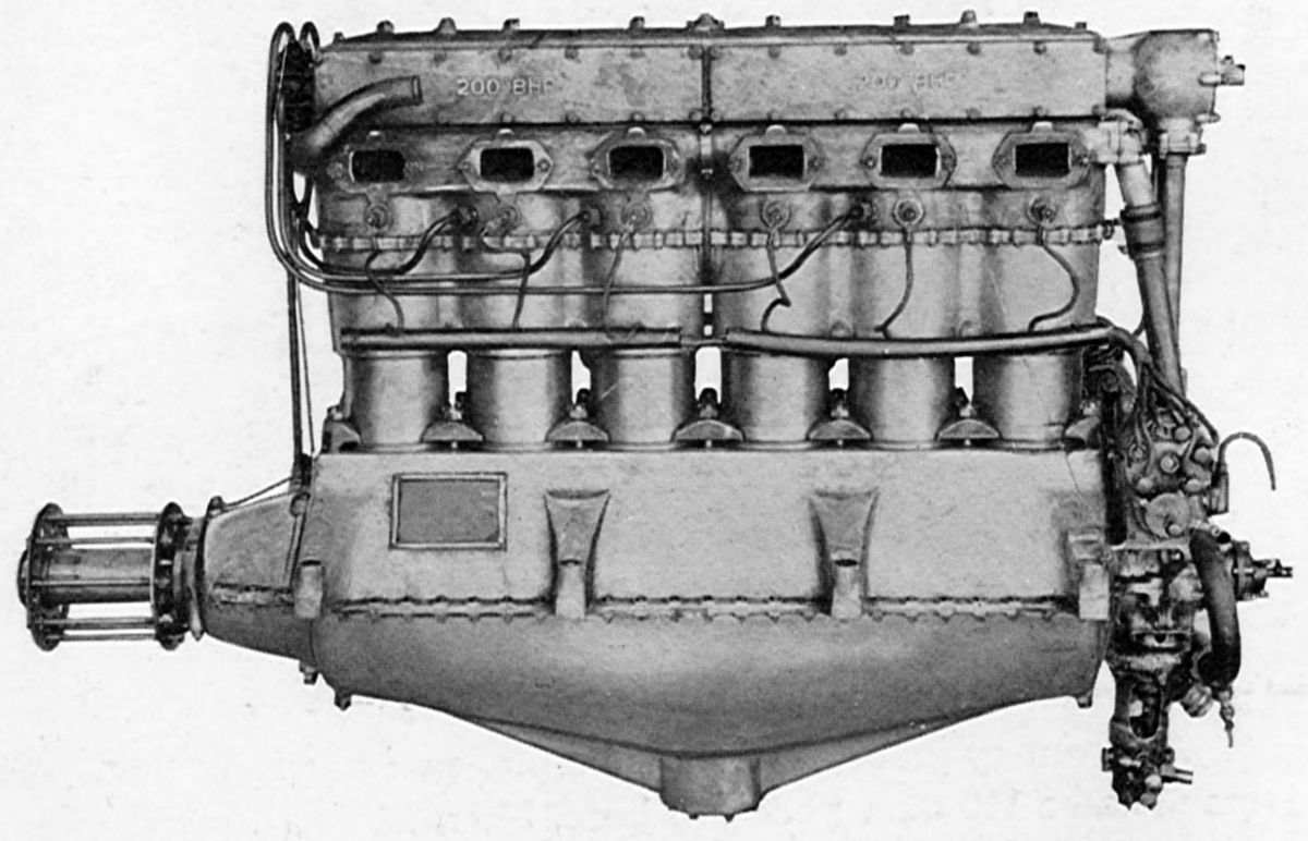
The Puma was a water-cooled vertical 6 with a 145 mm (5.109") bore, 190 mm (7.480") stroke, 18.825 l (1,148.76, in³) displacement and 4.96:1 compression ratio that was take-off rated 250 hp at 1,400 rpm; short-duration maximum power was 265 hp at 1,500 rpm Fuel and oil consumptions were 0.519 and 0.045 lb/hp/hr. Weighing 294 kg (648 lb), it was 1,778 mm (70") long, 613 mm (24.13") wide and1,183 mm (42.625") high. The cylinders were cast in blocks of three. Steel sleeves, open at both ends, were screwed into an aluminum casting that formed the heads and manifolds for three cylinders. The separate aluminum waterjacket that surrounded the cylinder barrels was bolted to the head casting and sealed by rubber gaskets. Bronze valve seats were expanded into place. Two exhaust valves and one inlet valve stood vertically in each cylinder. An overhead camshaft, enclosed by an oil-tight housing, directly operated the exhaust valves, and actuated the inlet valves via rocker arms. The inlet valve clear diameter was 66 mm (2.598") and the lift 11.2 mm (0.441");exhaust valve clear diameter was 44 mm (1.732") and the lift 9.5 mm (0.374"). Both valves had 45° seat angles . Inlet valves opened 7° late and closed 43° late; exhaust valves opened 58° early and closed 12° late. Two Zenith carburetors with 36 mm (1.417") venturis were bolted to the inlet-manifold flange on the cylinder head. A dry-sump pressure-fed lubrication system with gear-type pumps furnished 15 ‑ 20 psi oil pressure.
The crankshaft was carried in seven plain hearings. The connecting rods had H-section shanks and four-bolt caps. The aluminum alloy pistons were fitted with two compression and one oil scraper rings above the piston pin and one oil scraper below. Two Fellows EM-6 magnetos, mounted crosswise and driven from the vertical camshaft driveshaft, supplied dual ignition. Puma engines began production in August 1917 and continued until December 1918; at least 4,288 were delivered. Production continued as the Armstrong Siddeley Puma.
 |
 |
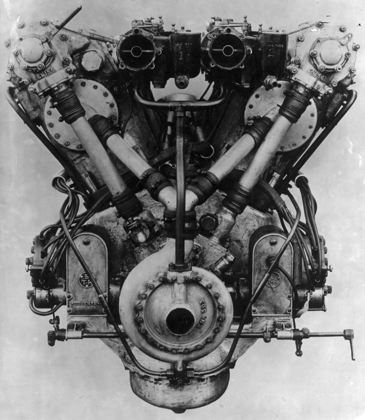 |
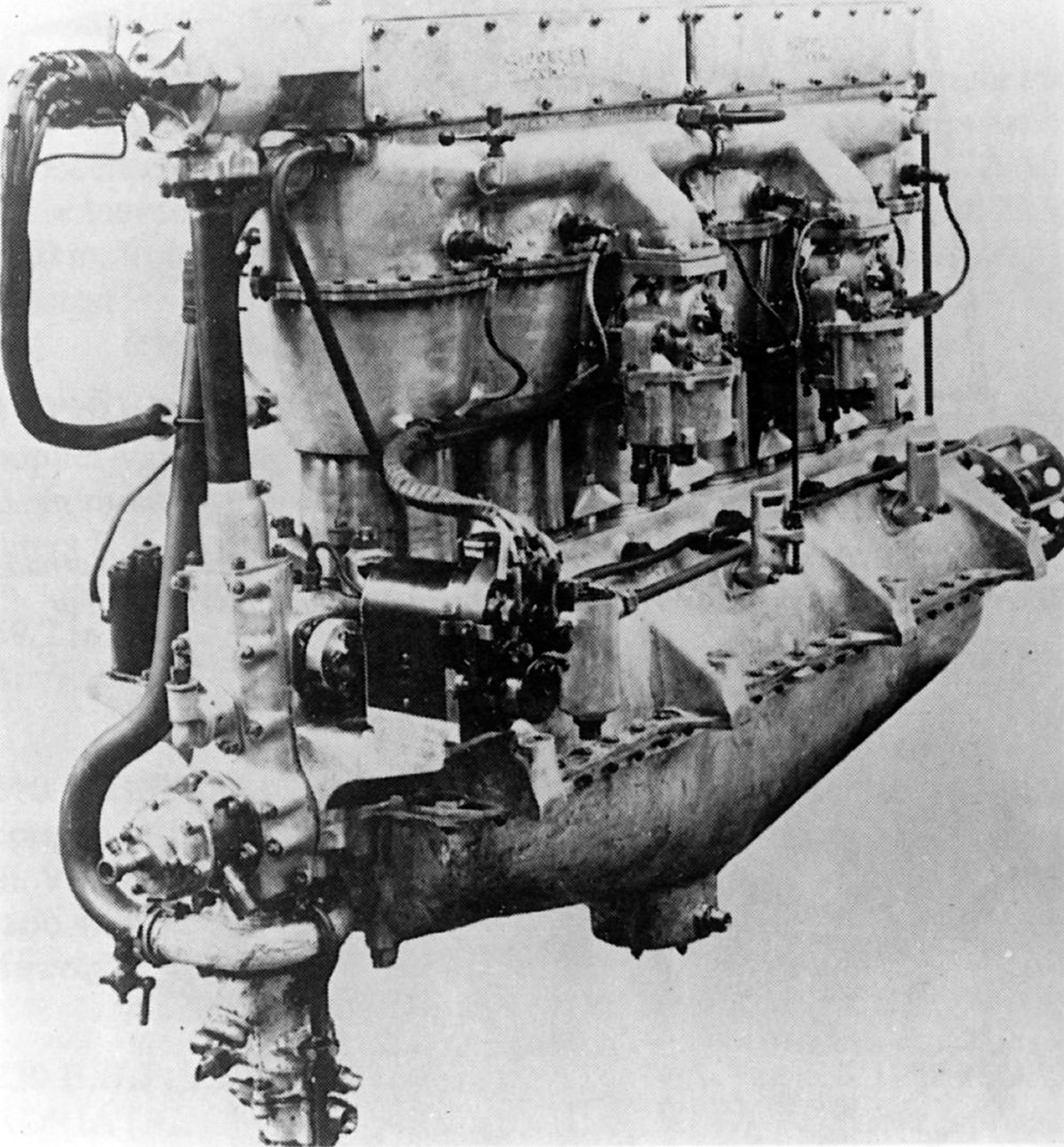
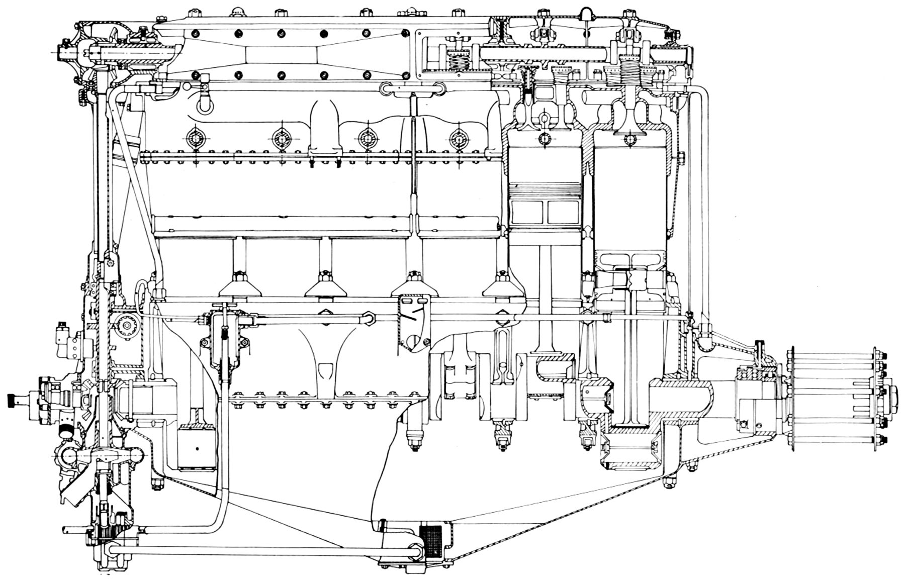
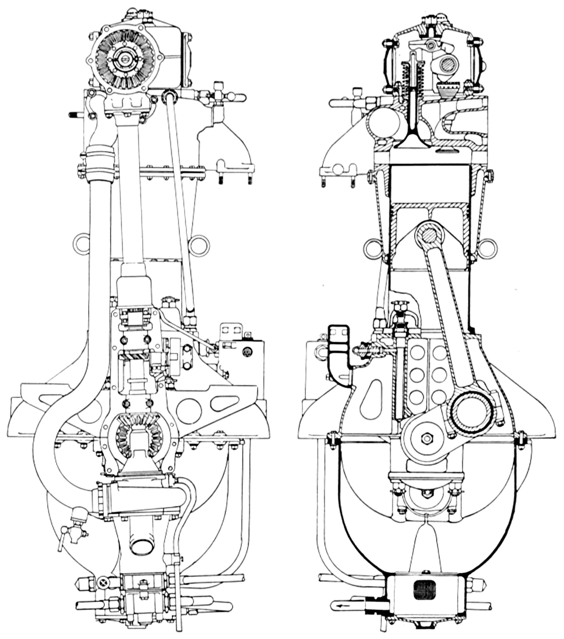
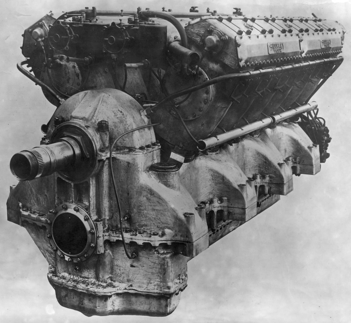
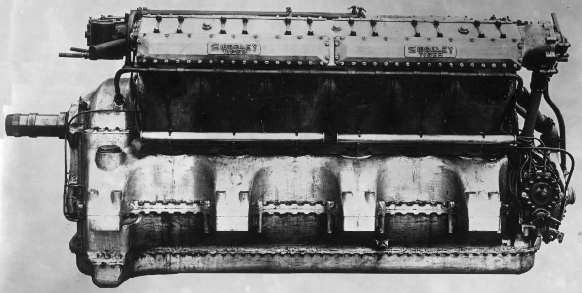
| Siddeley-Deasy Tiger (NARA) | ||
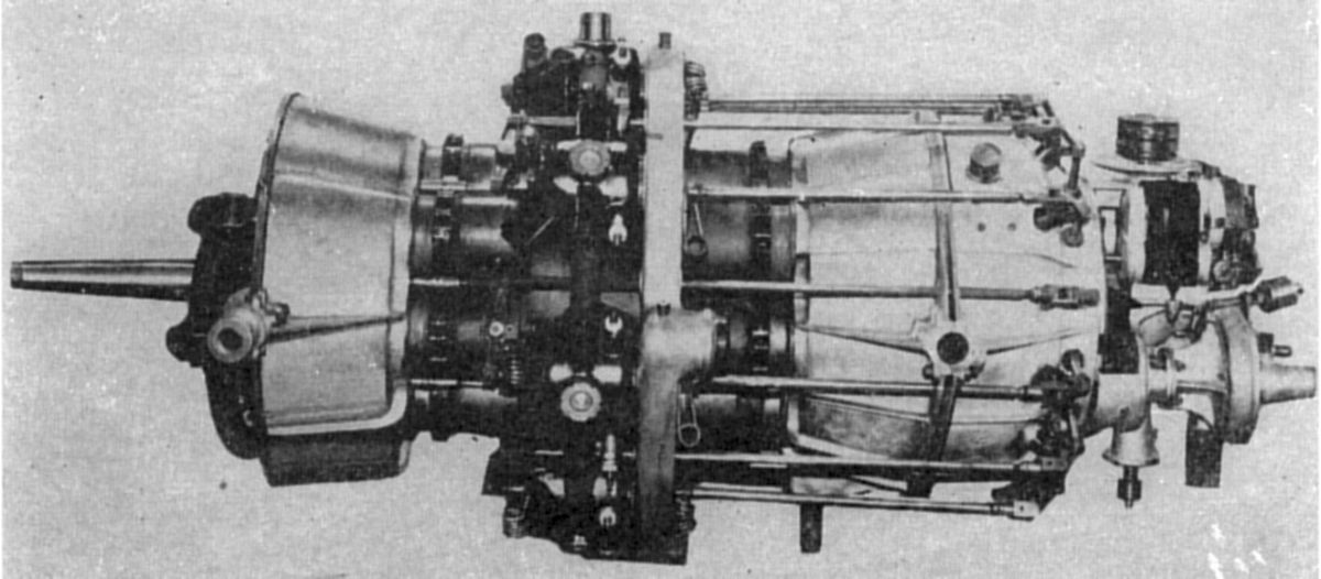
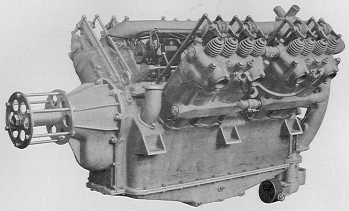
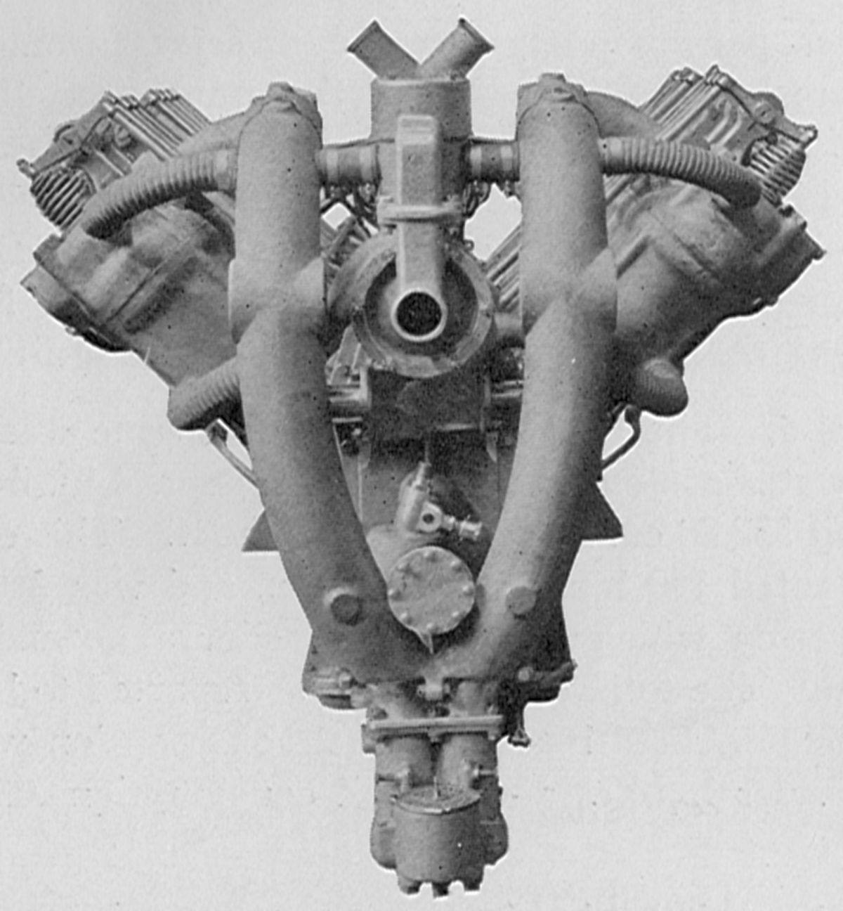
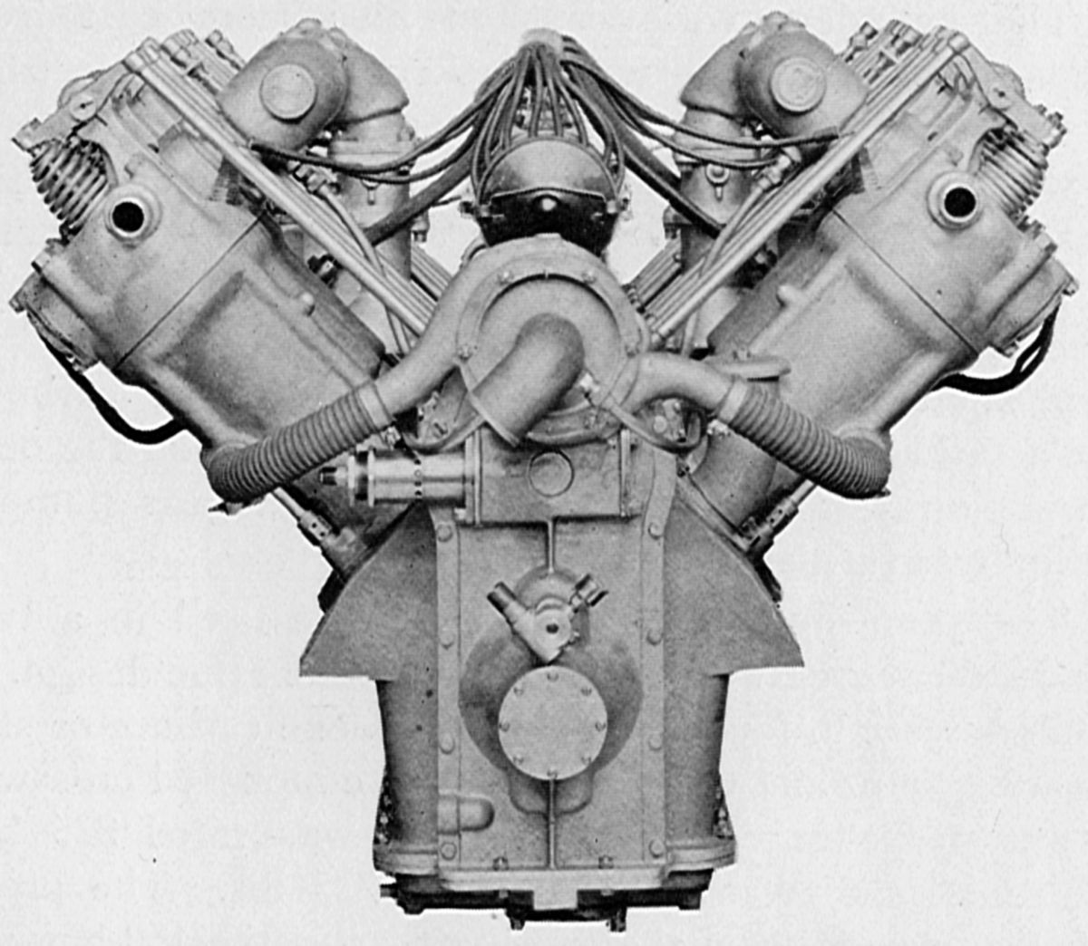
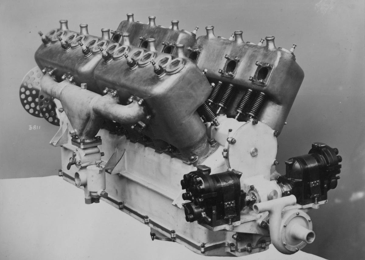
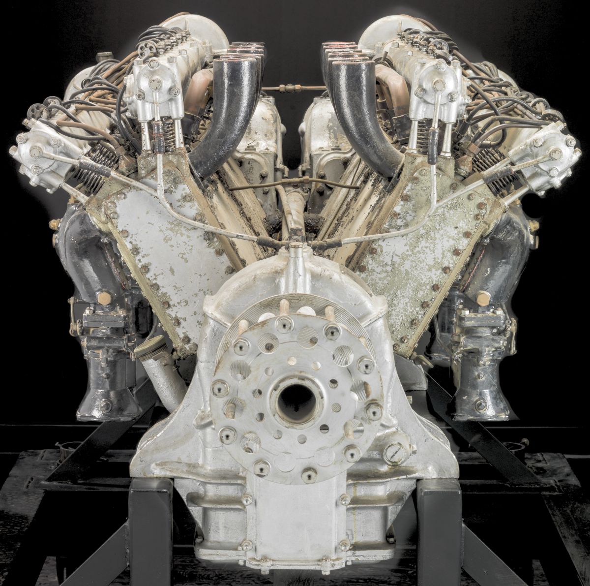
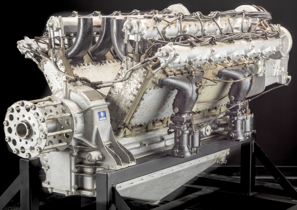
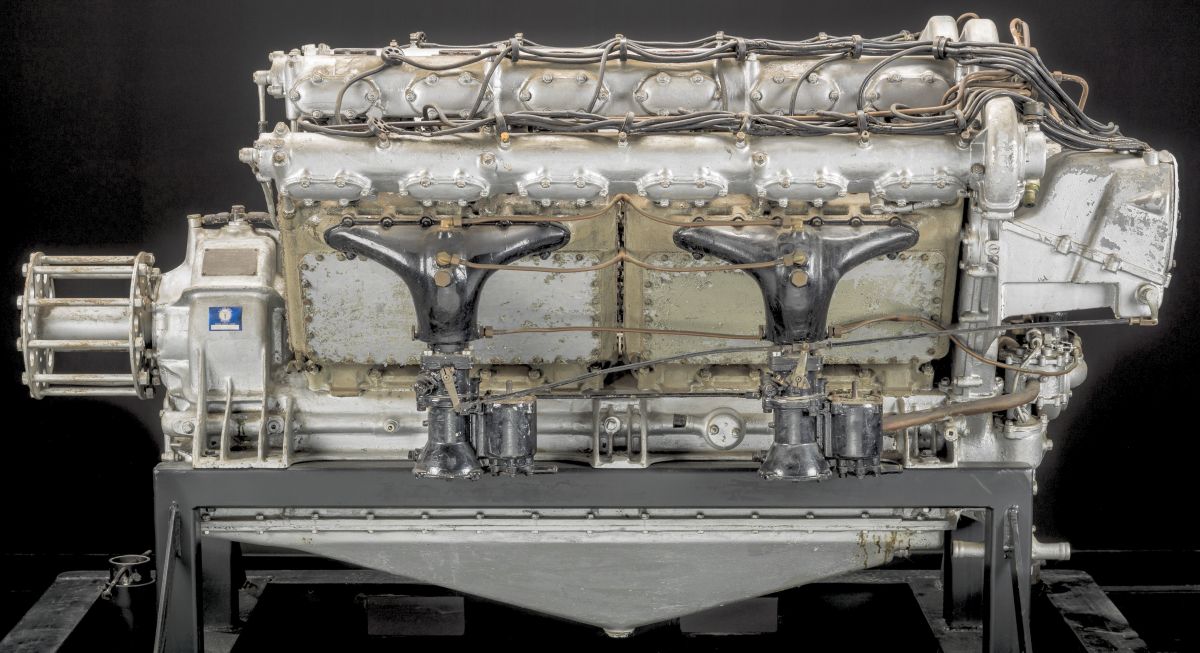
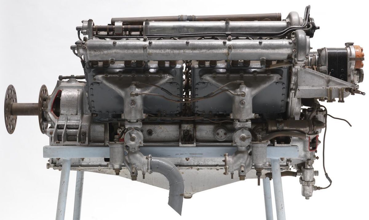
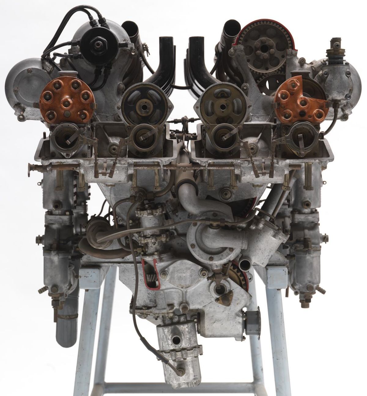
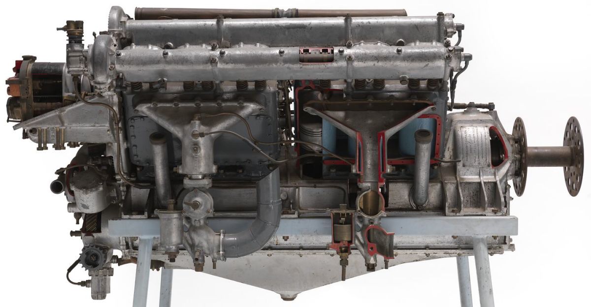
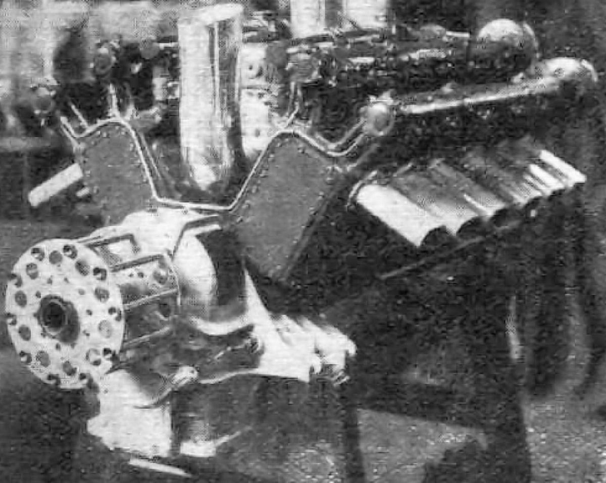
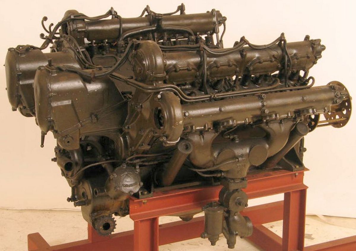
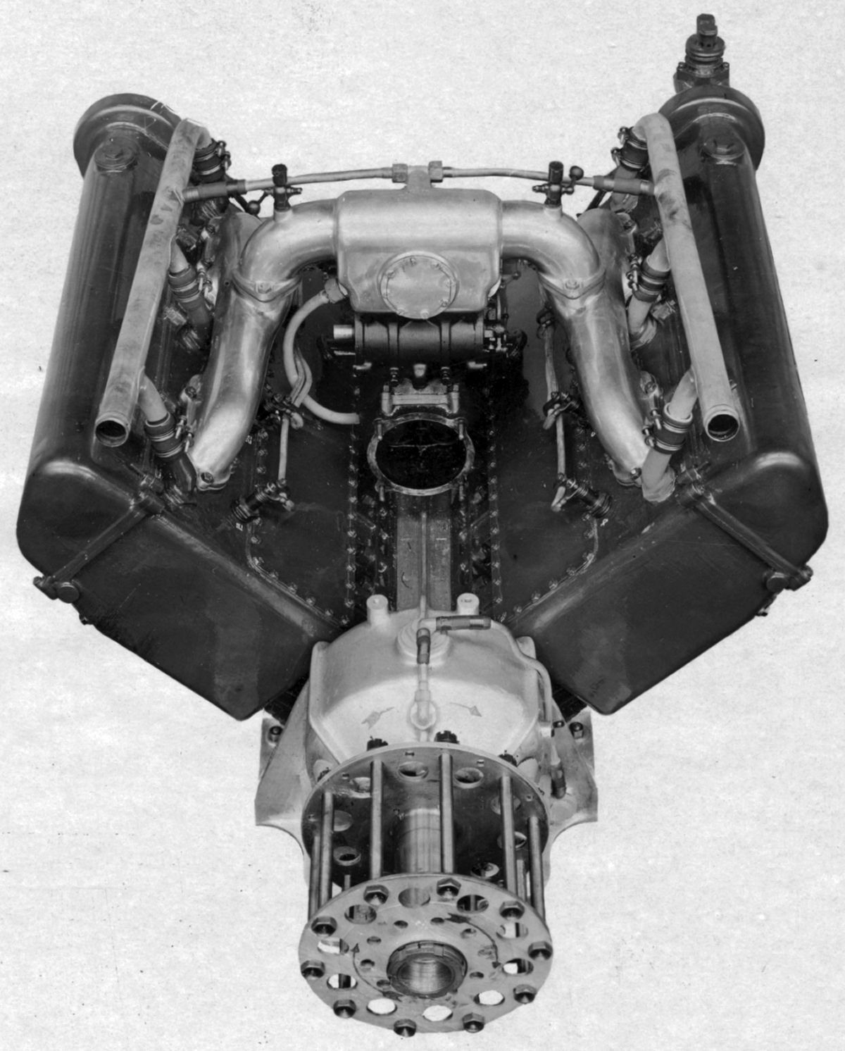
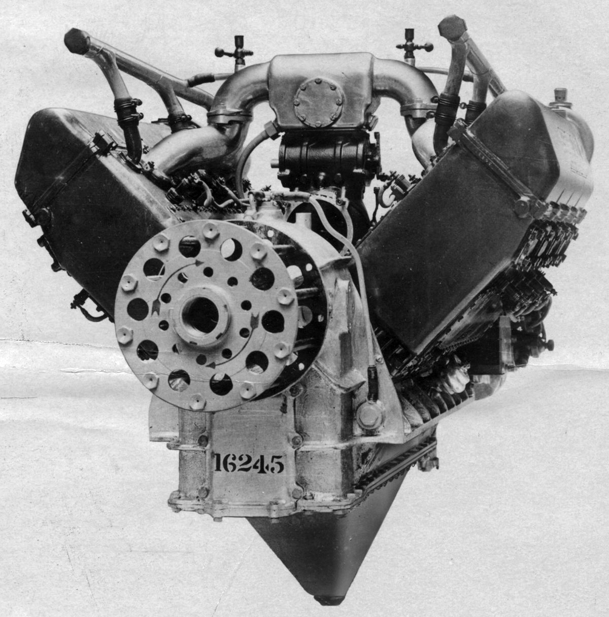
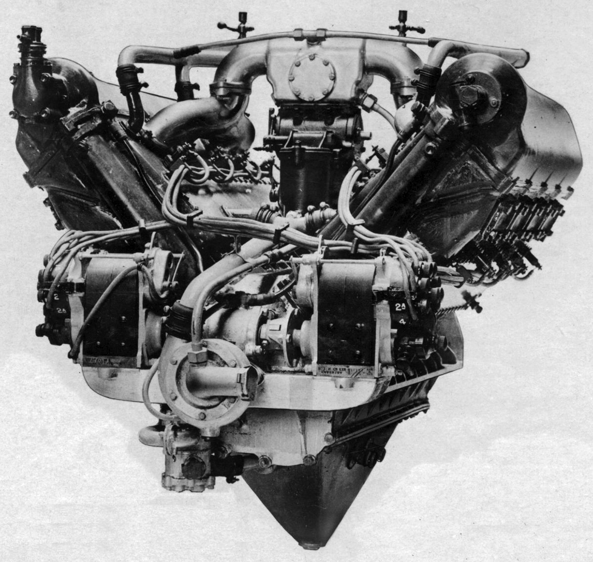
The Tiger, developed shortly after WWI using two modified Puma cylinder banks, was a 1.7889:1 spur-geared water-cooled 60° V-12 with a 160 mm (6.299") bore, 180mm (7.087") stroke, 43.429 l (2,650.22 in³) displacement and 5.2:1 compression ratio that was rated 600 hp at 1,650 rpm and 685 hp at 1,640 rpm. Weighing 612.4 kg (1350 lb), it was 2,066 mm (81.34") long, (850 mm (33.46") wide and 1,005 mm (39.57") high. While the cylinders were separate, the cylinder head, with intake ports, exhaust ports and water jacket, was an aluminum alloy casting. Steel liners, open at both ends, screwed into the head for a short distance, and the water jacket joint at the lower end was sealed by a round rubber ring pressed against the steel liner by an annular aluminum nut. The bronze valve seats were expanded into place. Two inlet and two exhaust valves were inclined in each cylinder. Each valve pair was actuated by a rocker arm from a central overhead camshaft, which could be moved longitudinally to provide a starting compression release. The tulip valves used volute springs and had 48 mm (1.890") clear diameters. The valve mechanism was enclosed by an oil-tight housing that extended over six cylinders. The six-throw seven-main-bearing crankshaft used fork-and-blade connecting rods. A dry-sump pressure-fed lubrication system used two scavenging and one pressure gear-type pumps and maintained 25 – 40 psi oil pressure at the main bearings. Two twelve-cylinder magnetos supplied dual ignition. Twin carburetors supplied the mixture. Starting could be either by an electric starter or compressed air. The centrifugal waterpump was driven through a small plate clutch.
Problems encountered during flight testing, including lowr eliability and insufficient power, resulted in the Tiger's cancellation.
Siemens-Halske
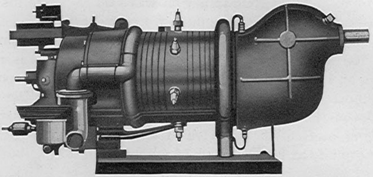
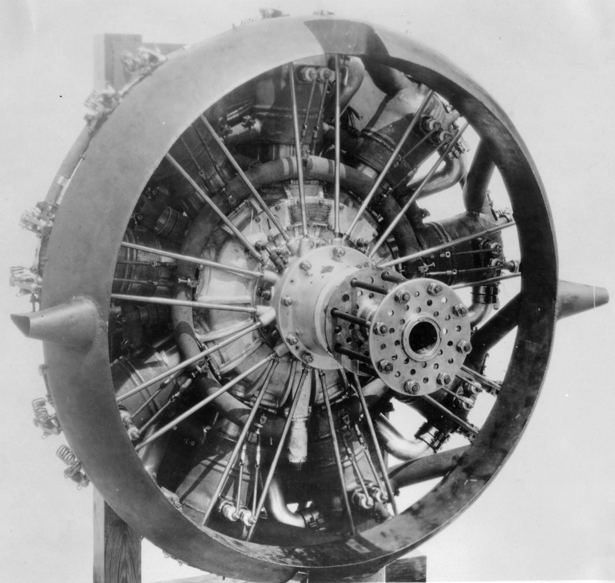
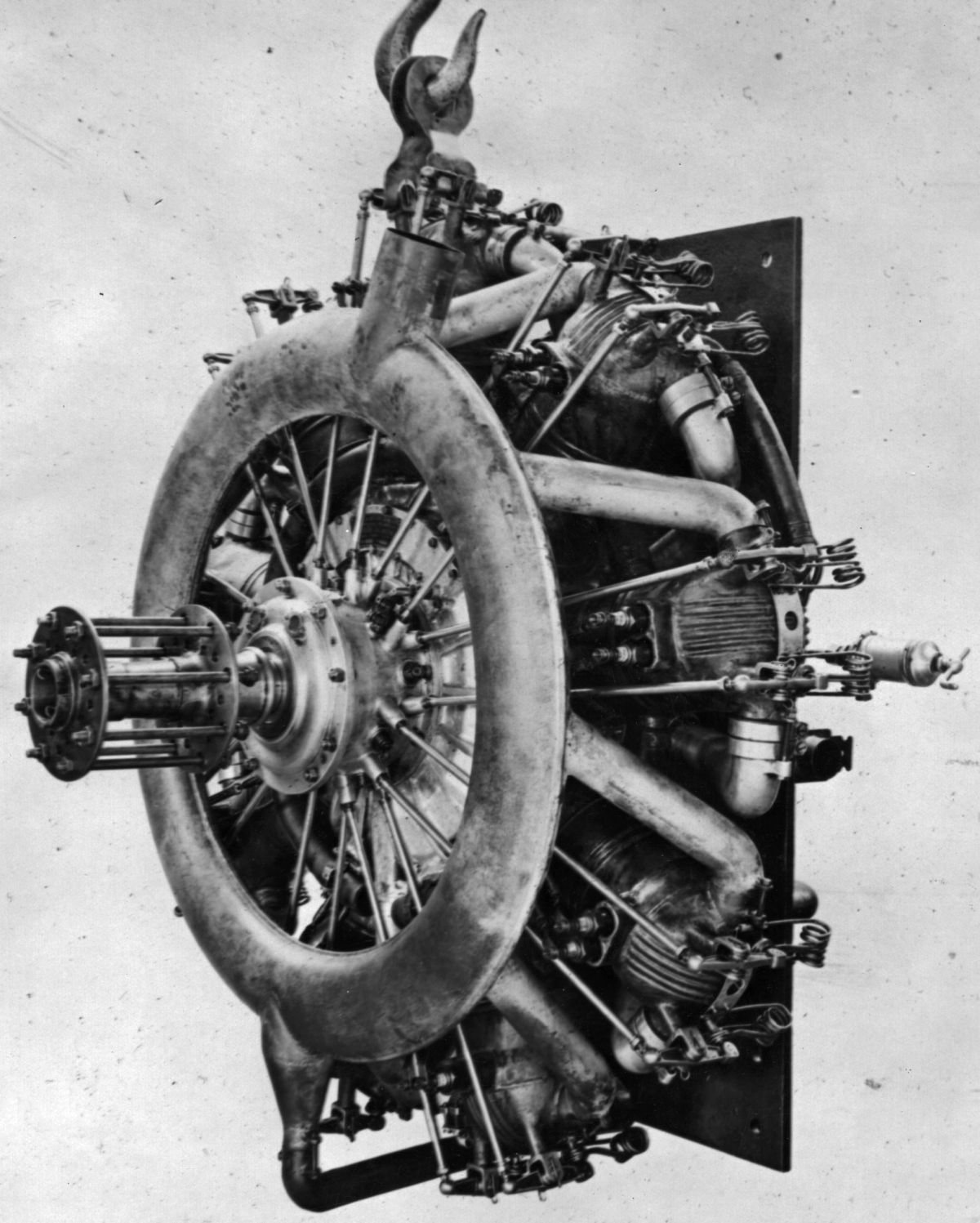
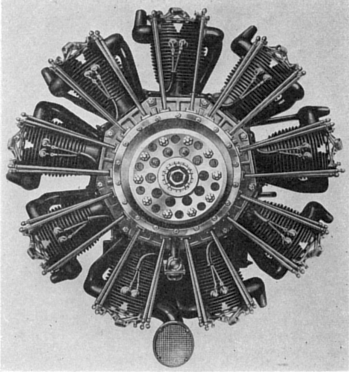
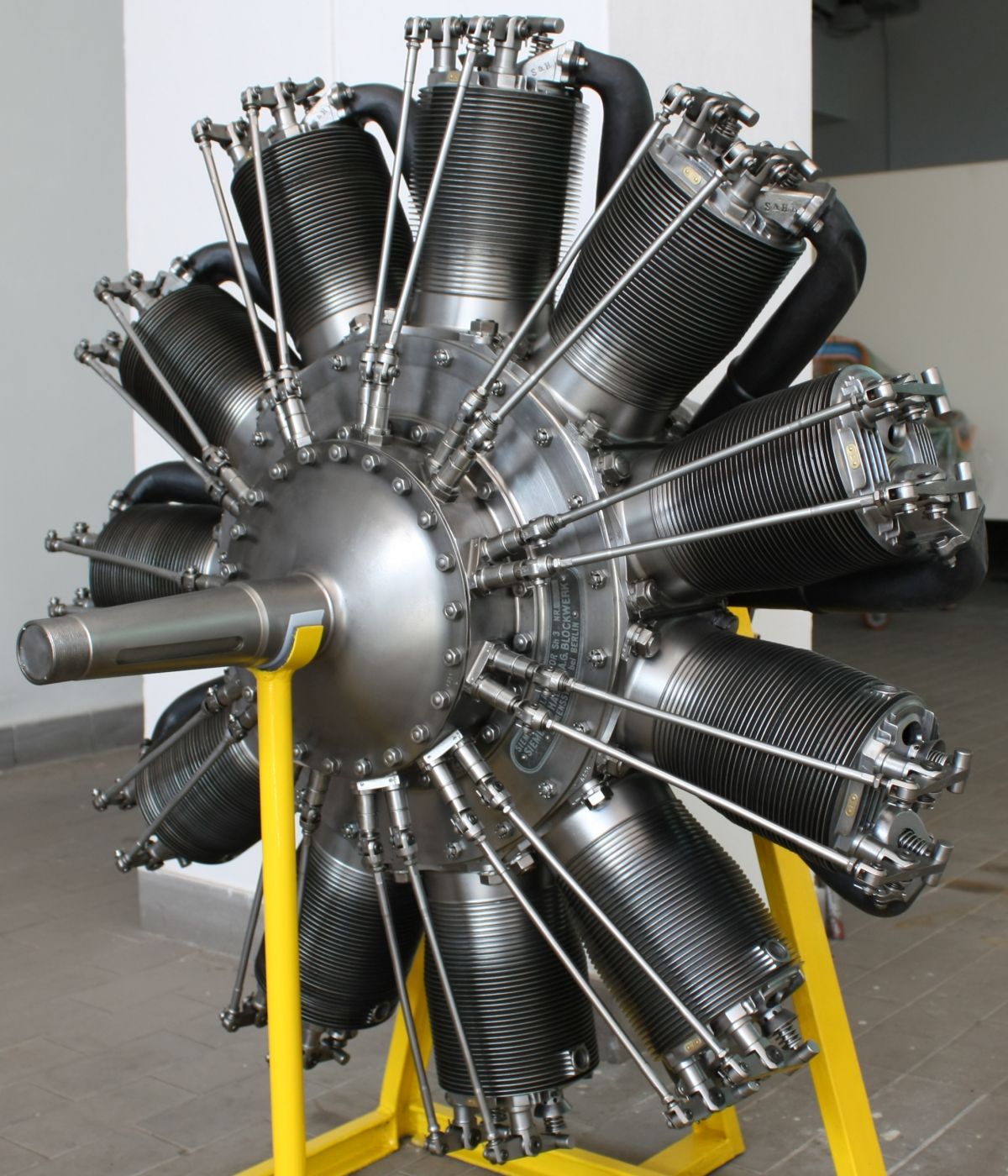
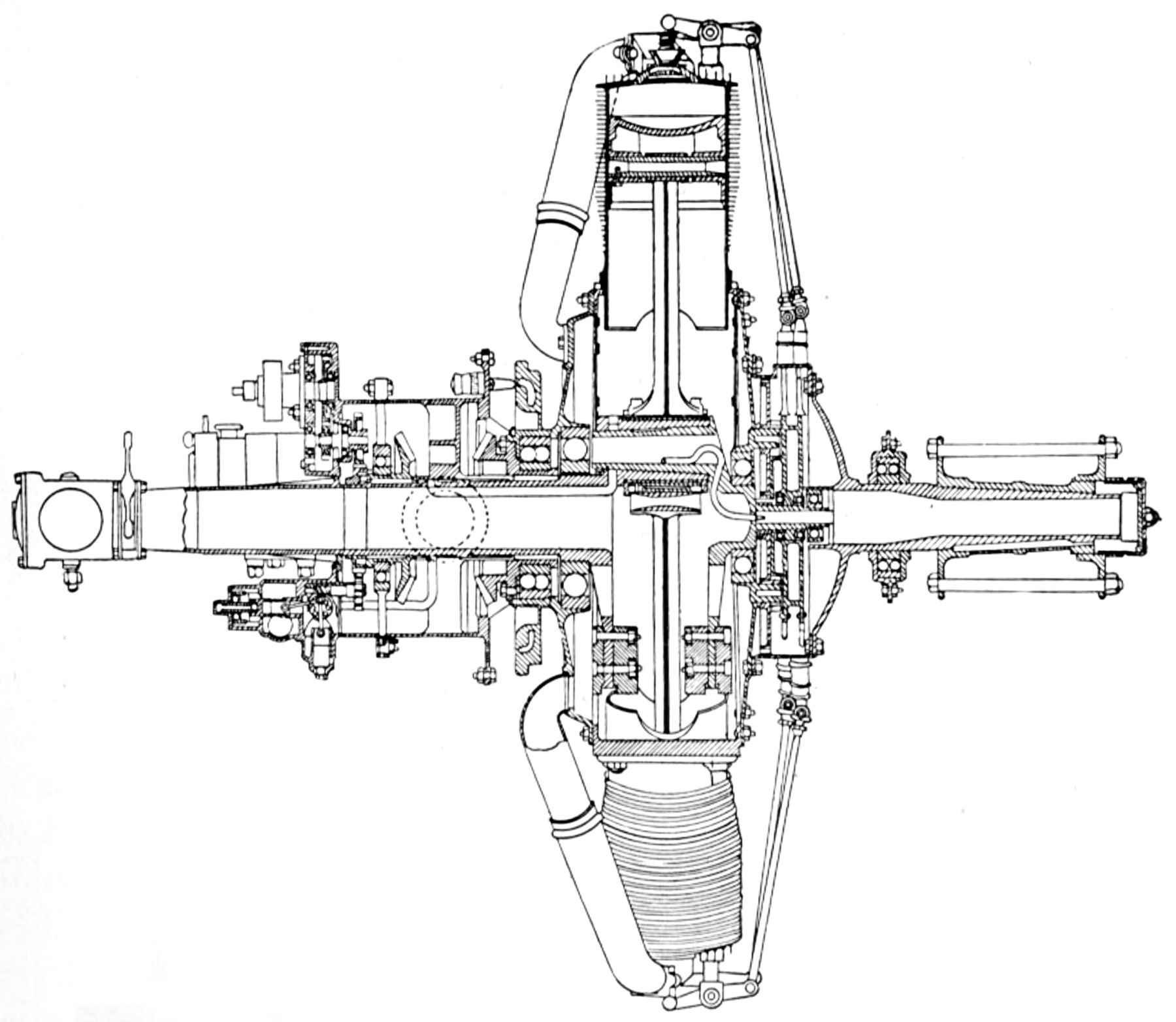
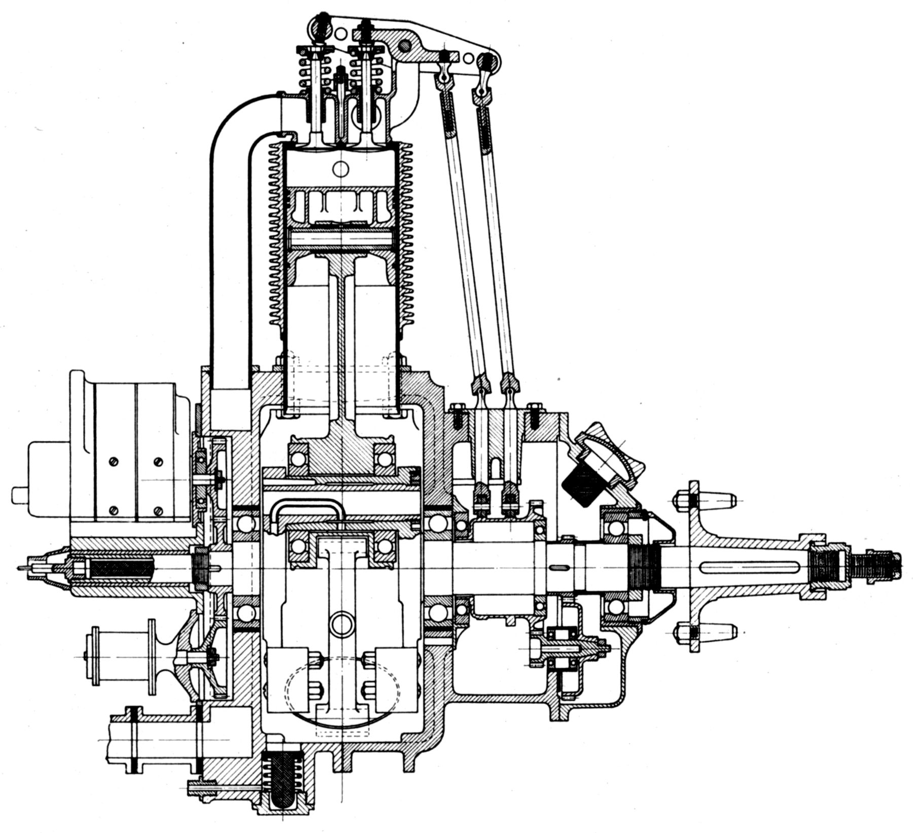
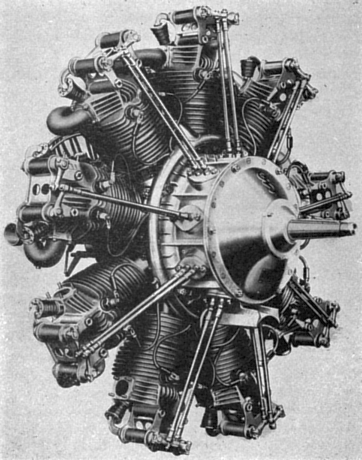
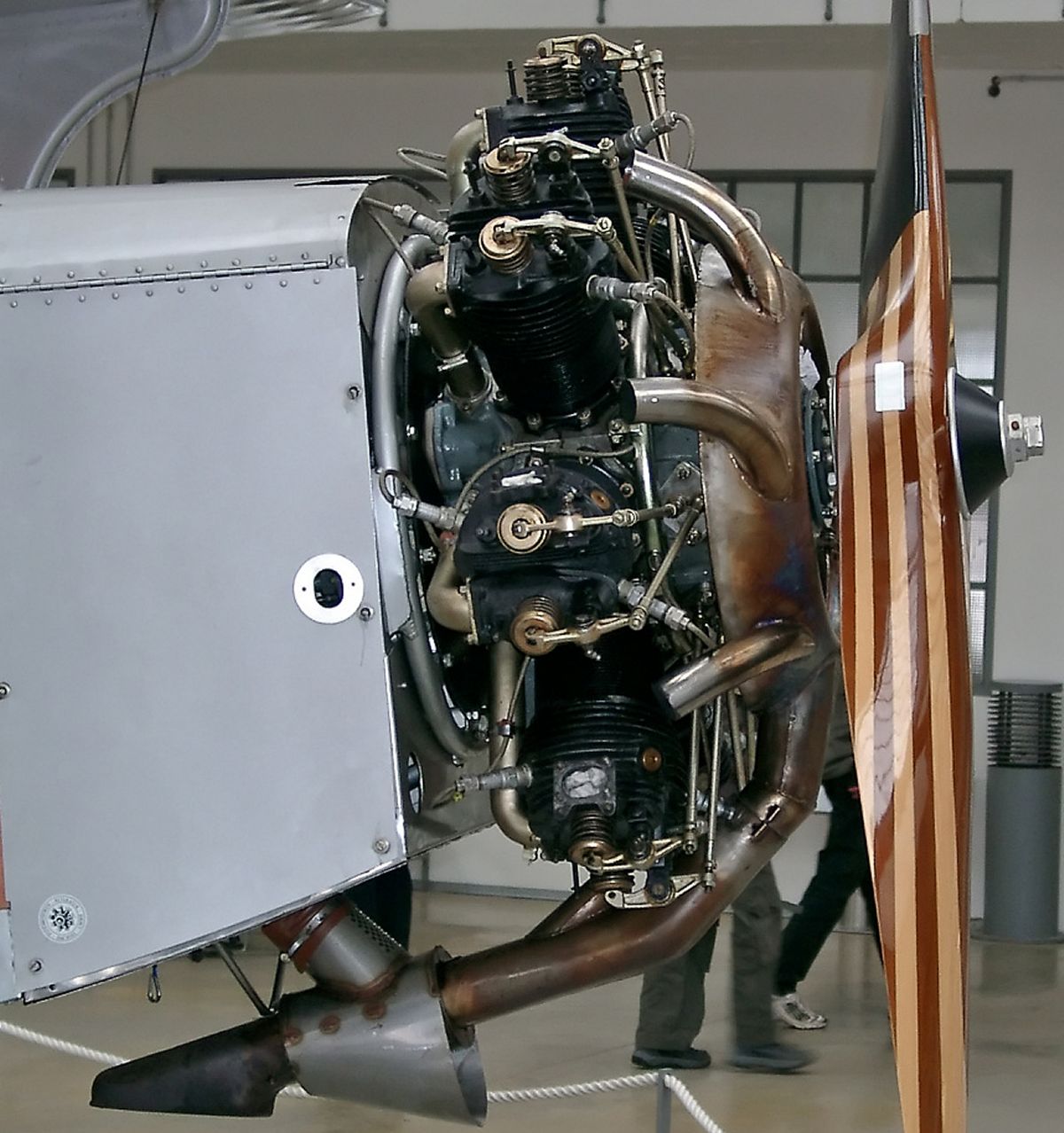
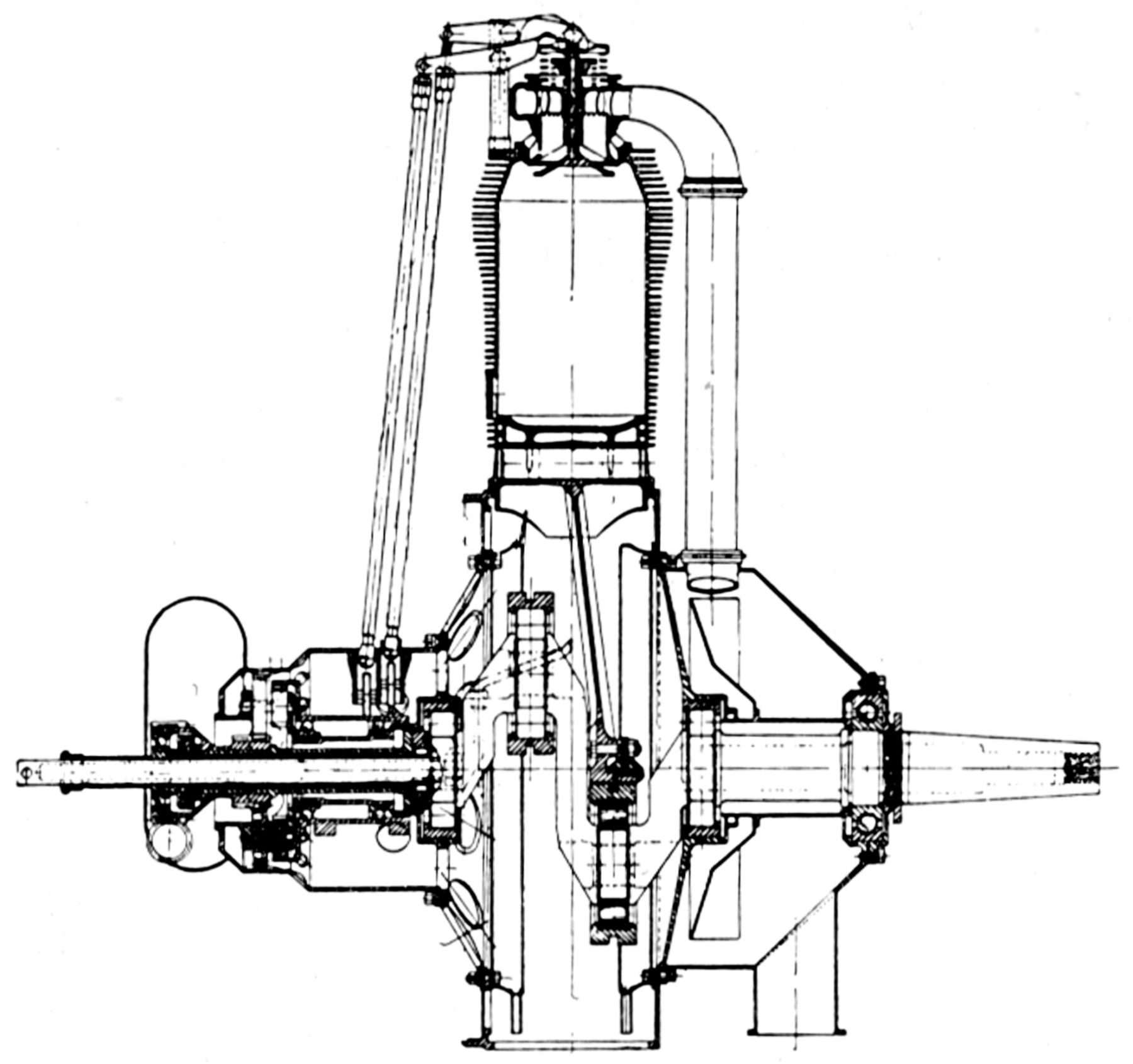
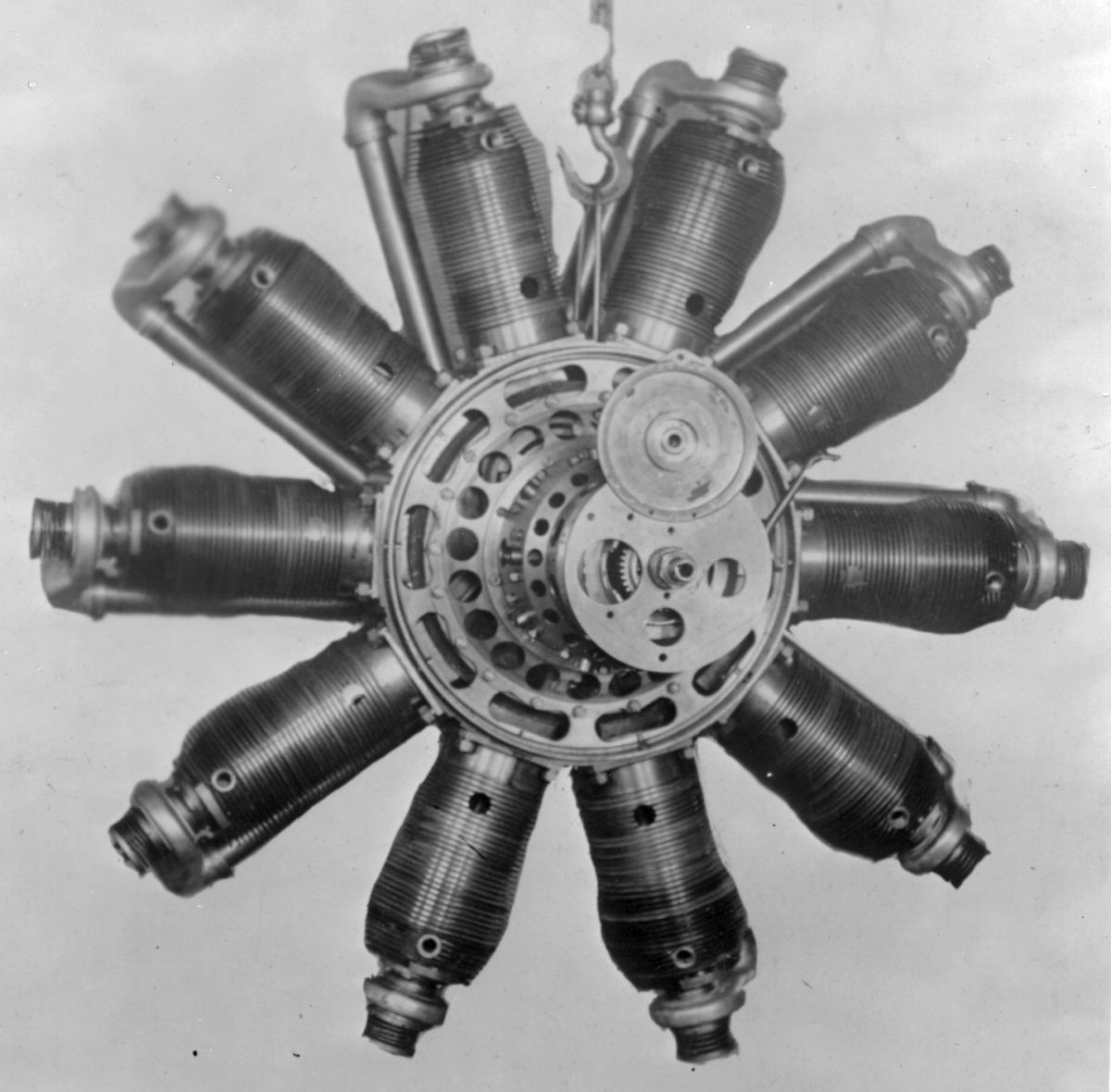
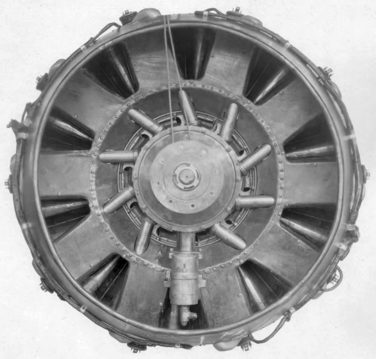
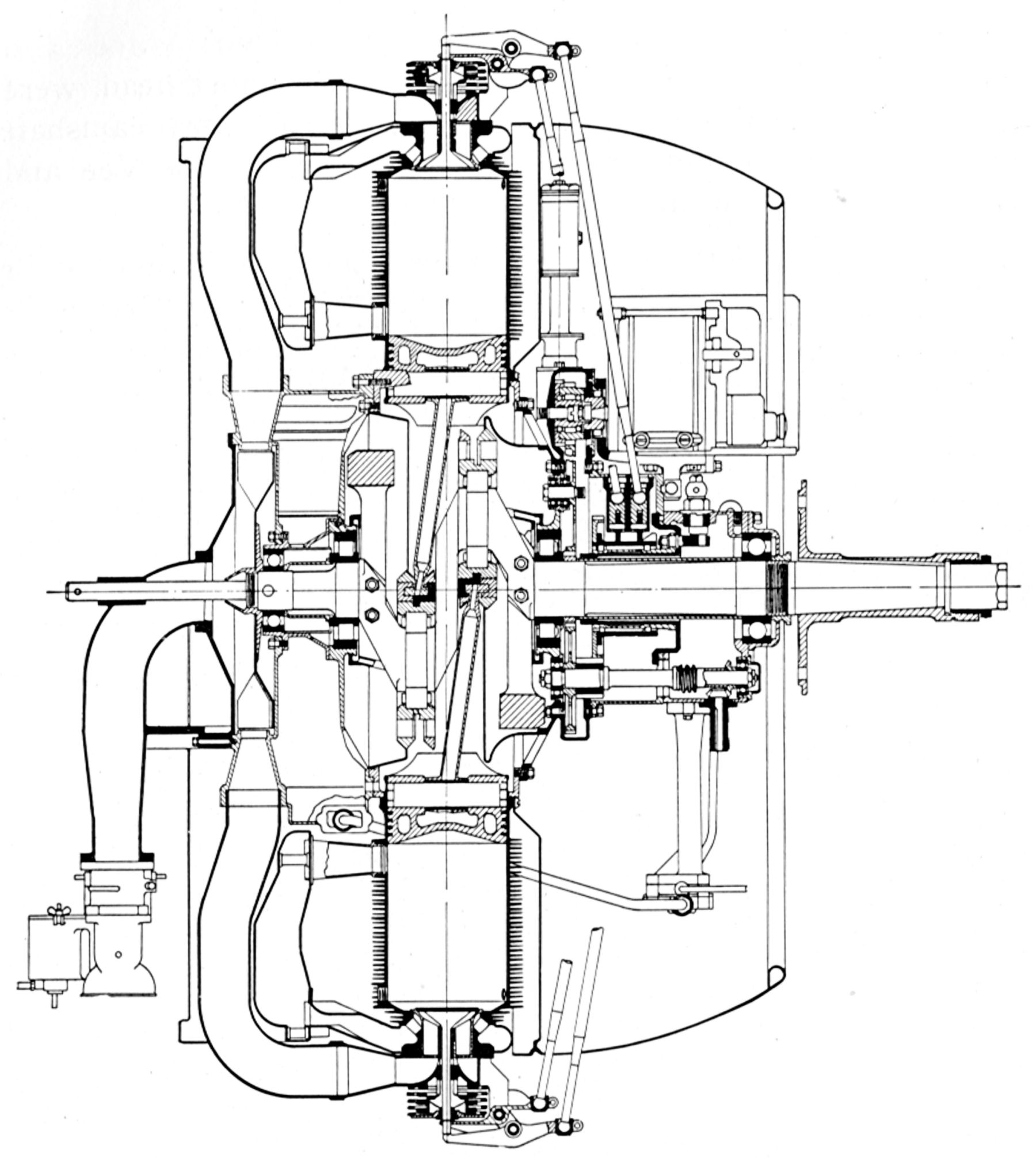
Ernst Werner Siemens (13 Dec 1816 ‑ 6 Dec 1892), a German electrical engineer, inventor and industrialist, and Johann Georg Halske (30 Jul 1814 ‑ 18 Mar 1890), a German master mechanic, founded Telegraphen-Bauanstalt von Siemens & Halske on 12 Oct 1847. Siemens-Halske manufactured telegraph equipment under Charles Wheatstone's 1837 patent and built an early European telegraph line from Berlin to Frankfurt. During WWI, Siemans-Halske built air-cooled differential rotary engines (US 1,084,192A) that geared the crankshafts to the crankcase and cylinders so that the propeller rotated in one direction and the cylinders in the other. This achieved the same number of firing impulses as a standard rotary engine running at twice the speed, with only minimal added complexity. Reducing the propeller speed allowed the use of larger, more efficient propellers and reducing the cylinder speed cut down the cylinder drag, along with the rotating mass gyroscopic precession effects.
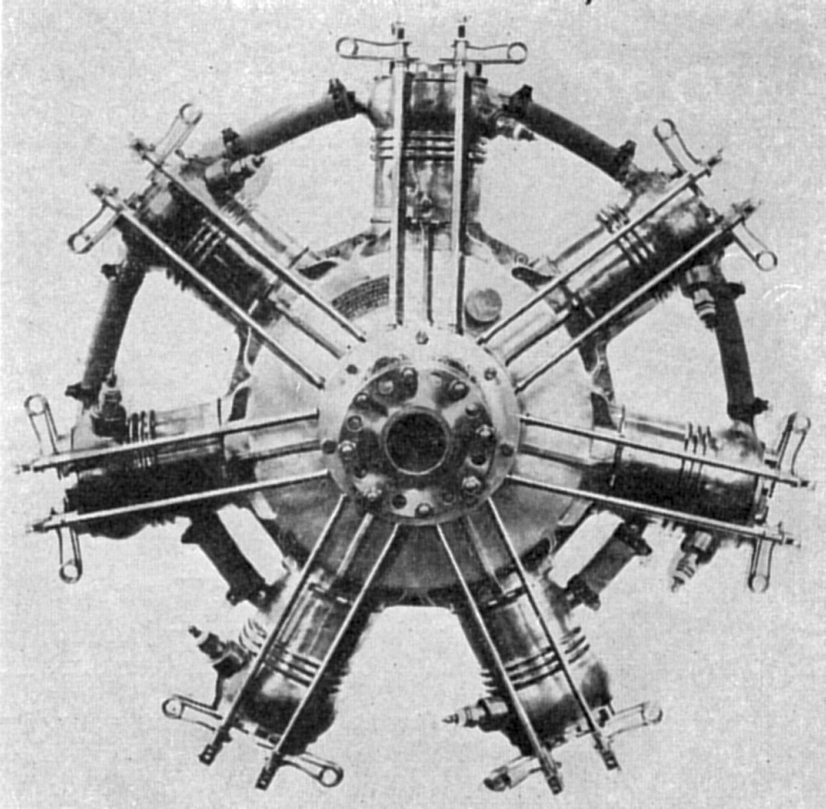
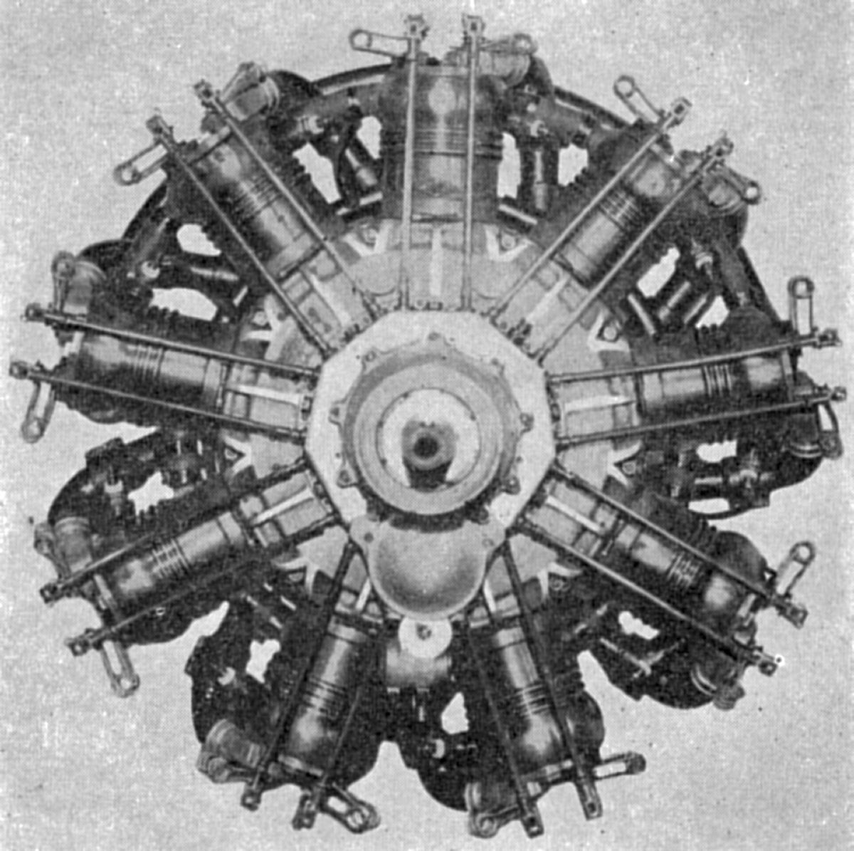
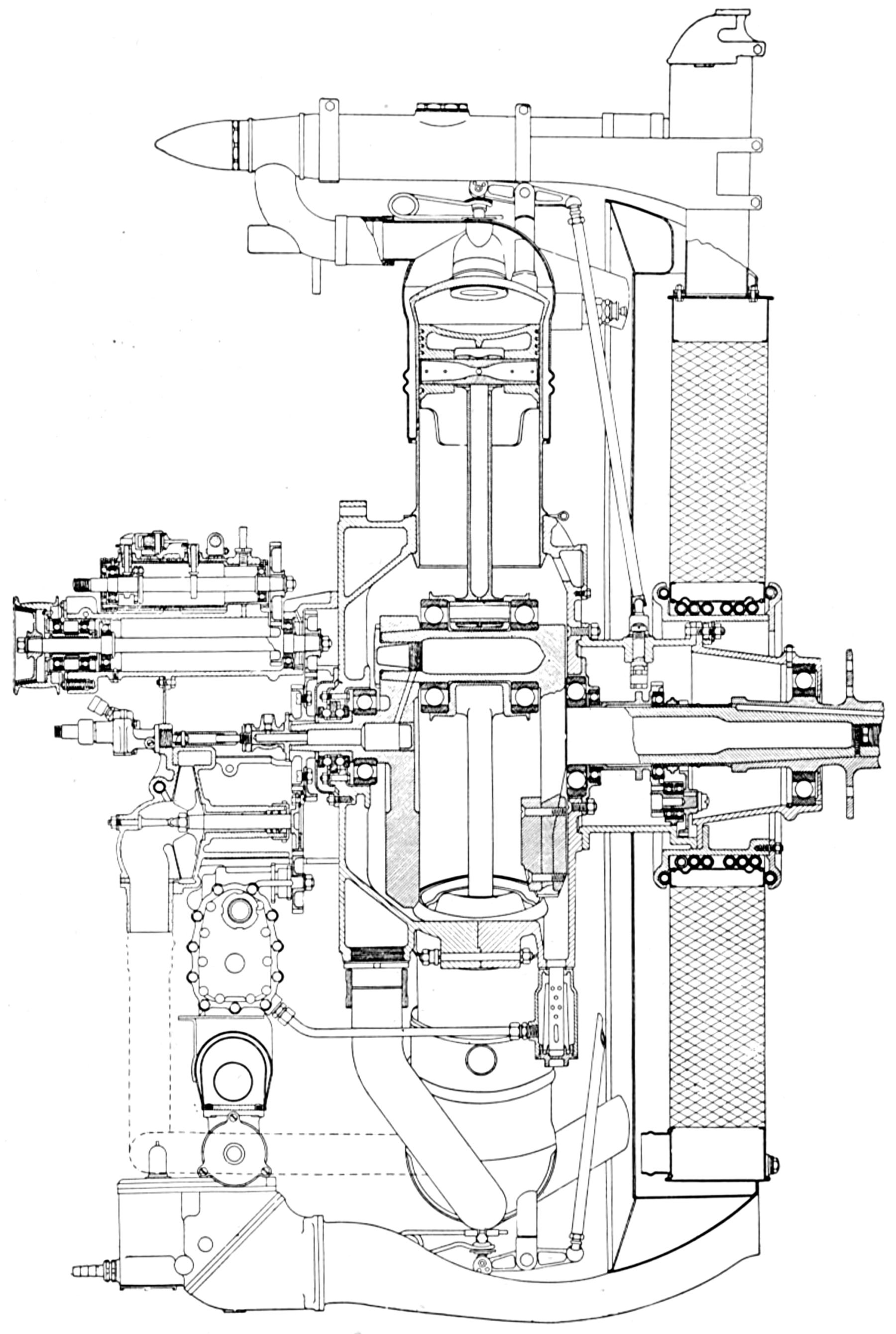
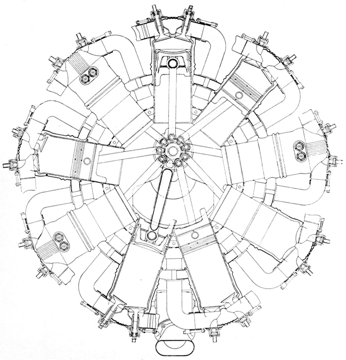
The 110-hp model was a rotary 9 with a 114 mm (4.488") bore, 130 mm (5.118") stroke, 11.942 l (728.76 in³) displacement and 3.96:1 compression ratio that delivered 110 ‑ 115 hp at 900 propeller rpm. Fuel and oil consumptions were 0.581 and 0.077 lb/hp/hr. Weight was 194 kg (428 lb), diameter was 965 mm (38") and length was 930 mm (36.6"). The steel cylinders had integral cooling fins, and the exhaust valves in the cylinder head centers were operated by push rods and rocker arms. The inlet valves, located in the piston crowns, were opened mechanically by cams on the connecting rods. A bevel gear on the crankshaft and a similar gear attached to the crankcase both meshed with pinions in the stationary transmission housing, effecting the differential rotation. The single-throw two-piece crankshaft was joined by a taper at the crankpin end. Mounted in large radial ball bearings were counterweighted disc sections that served as crank cheeks. Articulated connecting rods attached pistons fitted with two sets of double rings above the piston pin. Two magnetos were mounted cross-wise on brackets attached to the stationary transmission housing. Below the transmission housing was a two-piston oil pump.
 |
 |
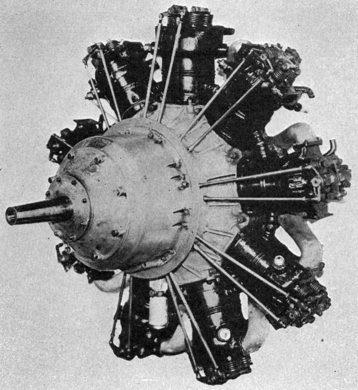
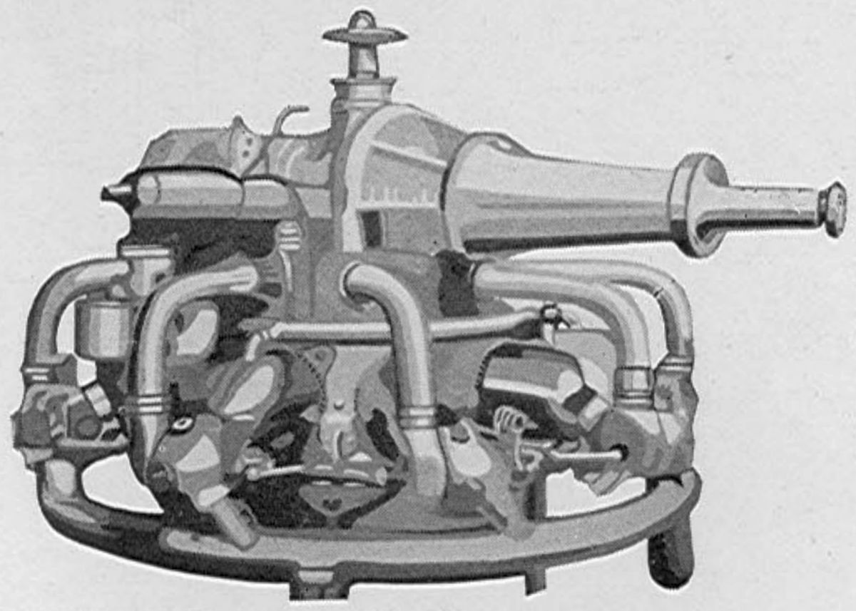
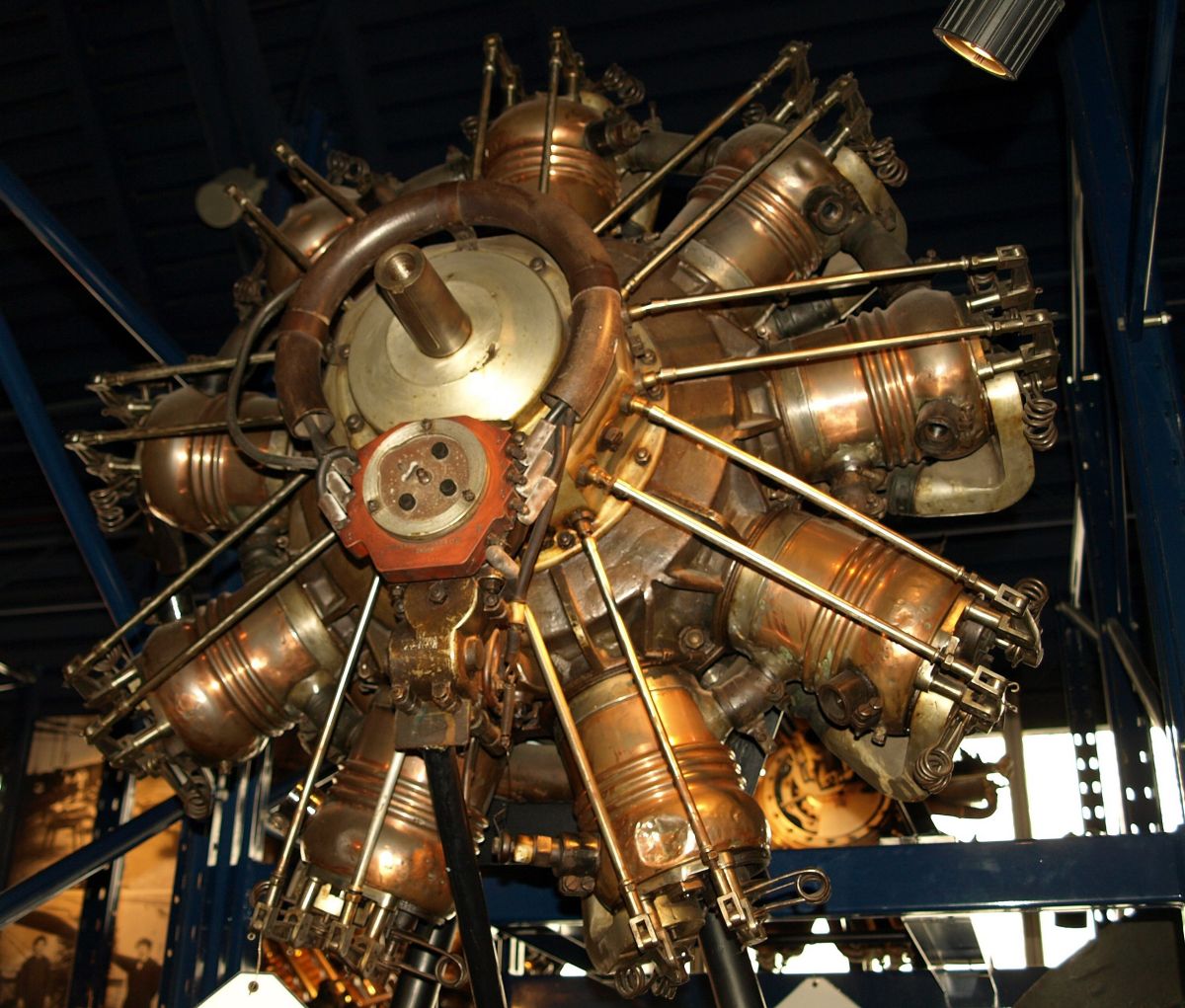
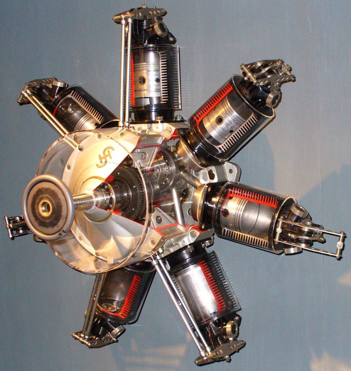
| Sh.IIIa (Wiki, A39) | |
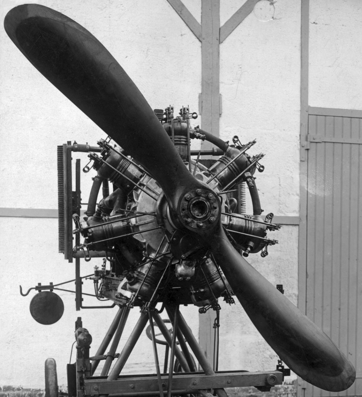
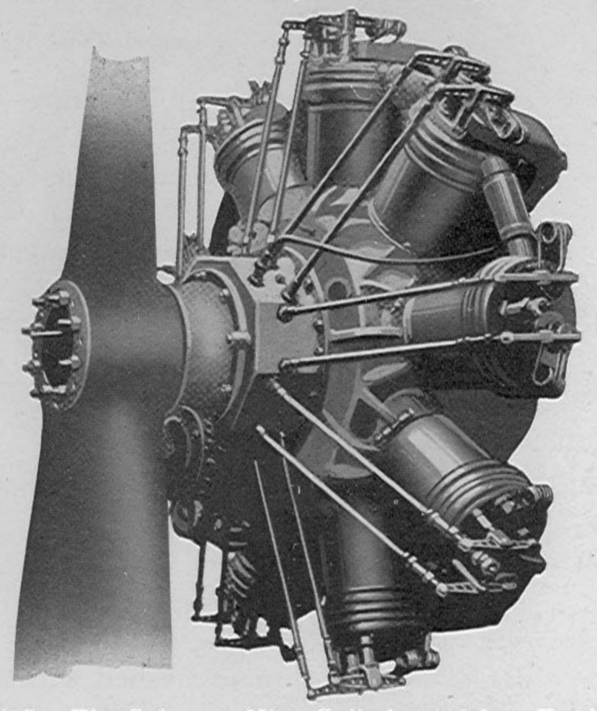
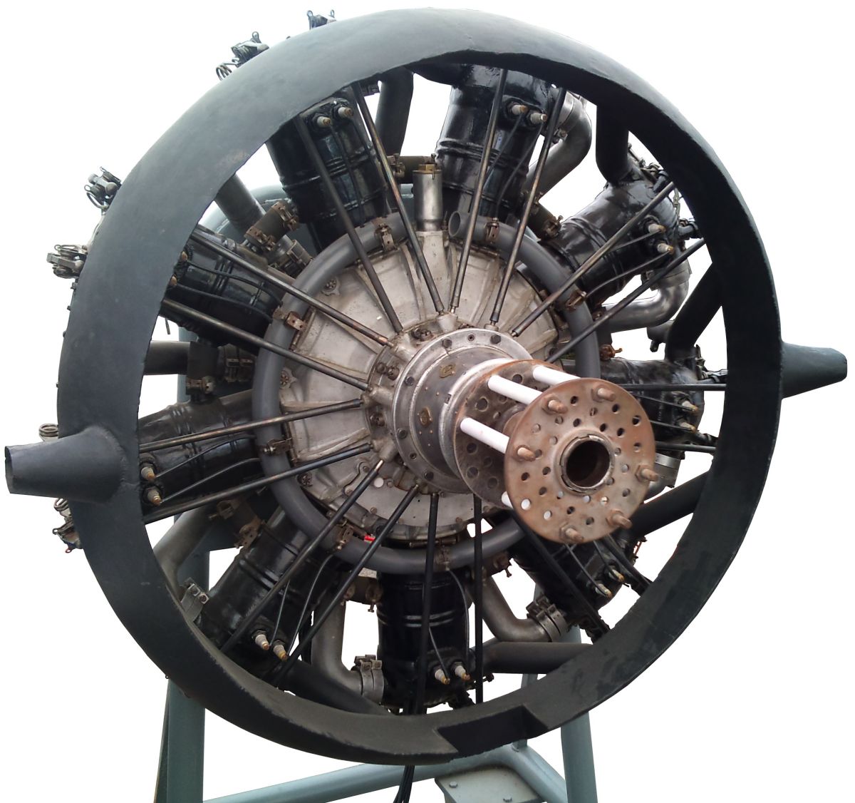
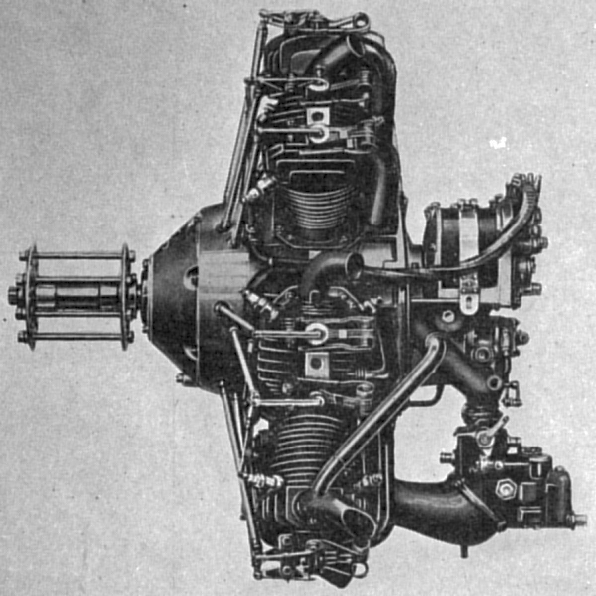
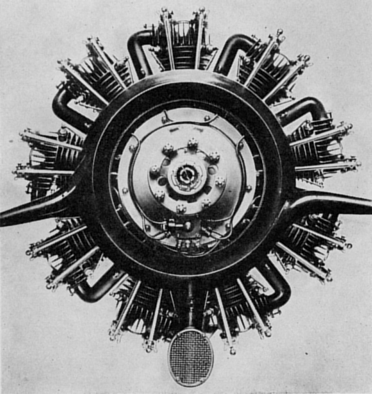
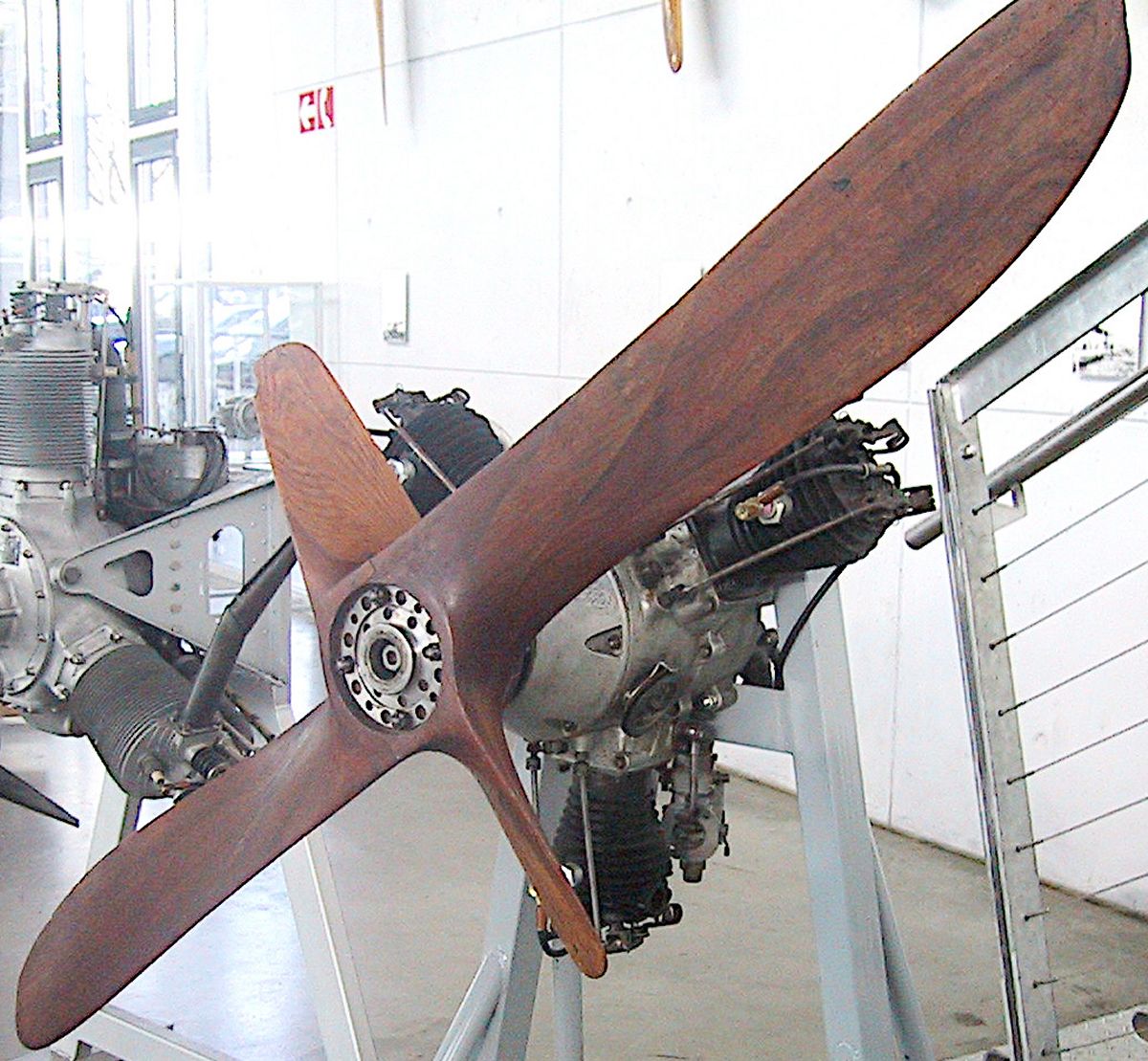
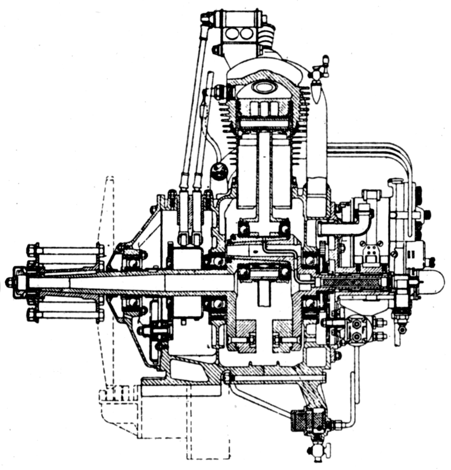
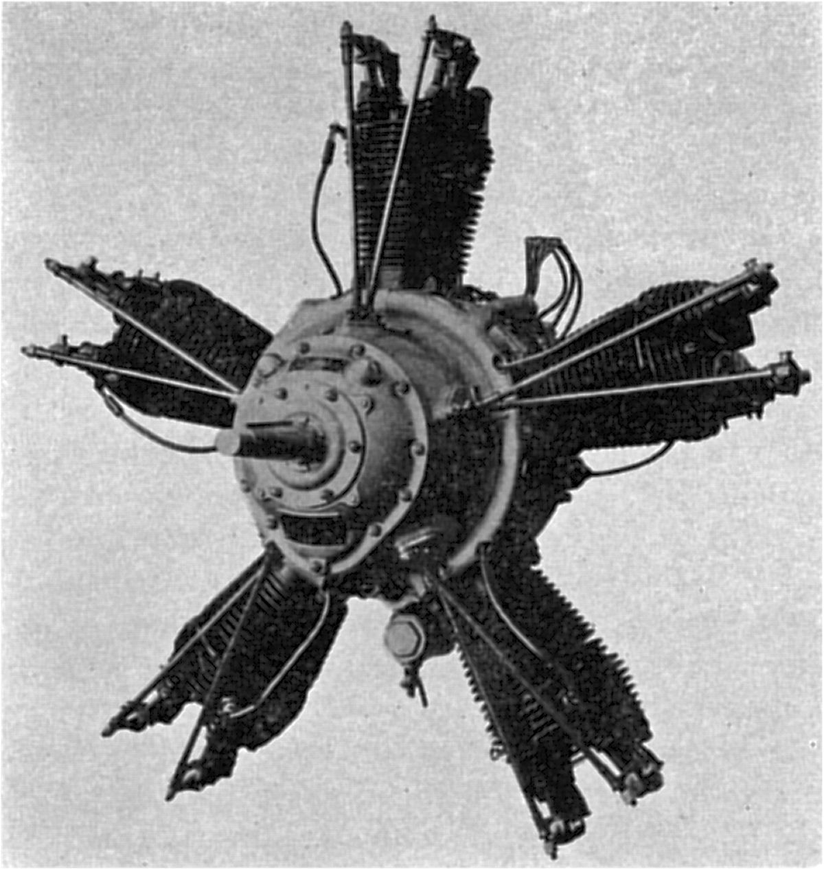
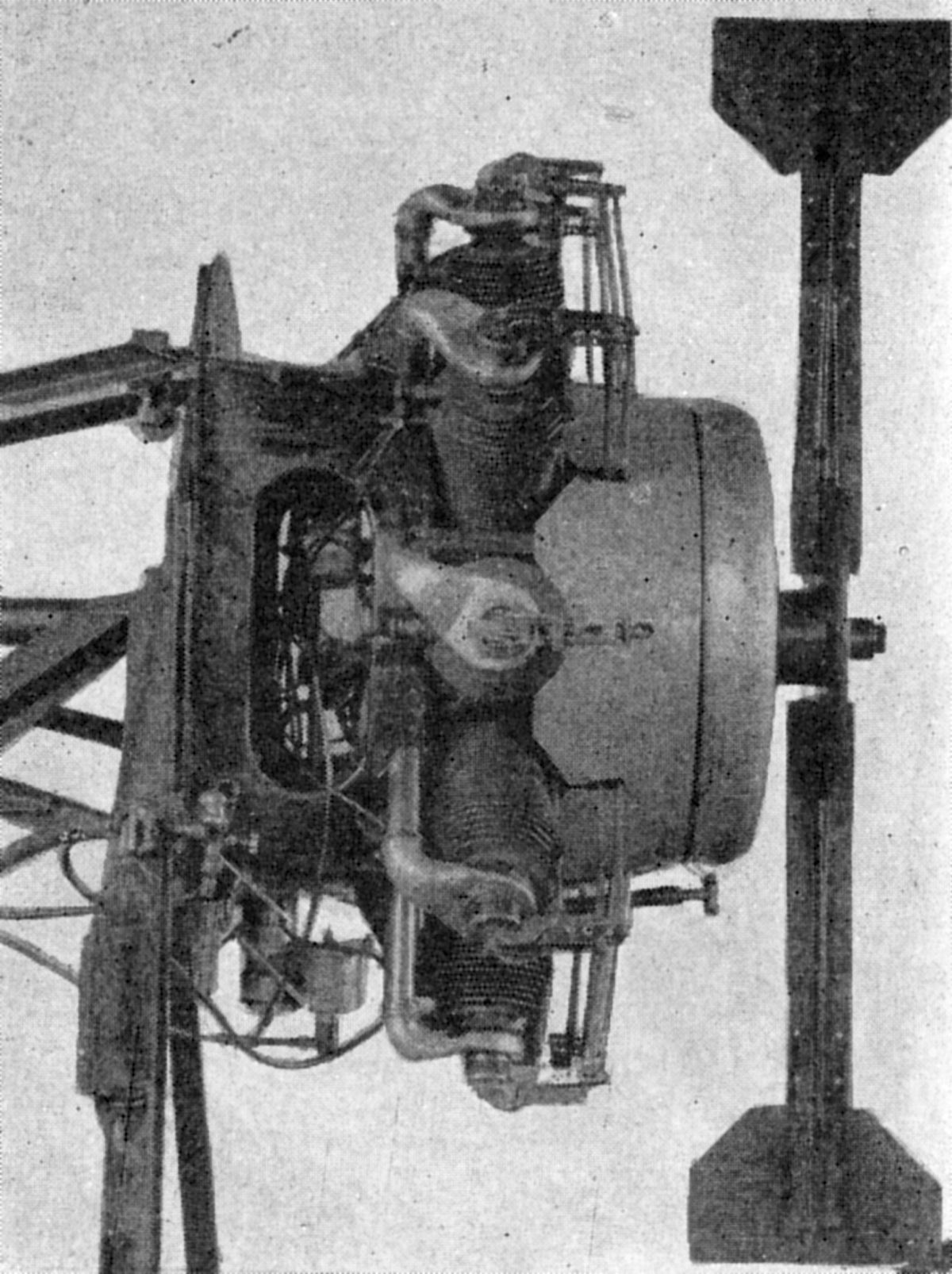
The Sh.III was a rotary 11 with a 124 mm (4.882") bore, 140 mm (5.512") stroke, 18.597 l (1,130.01 in³) displacement and 5.1:1 compression ratio that produced 160 hp at 900 propeller rpm. The Sh.III could be throttled, idling as low as 350 propeller rpm. Fuel and oil consumptions were 0.62 and 0.165 lb/hp/hr, and weight was 194 kg (428 lb). Unlike the 110-hp model, the propeller was mounted to a crankcase extension. The aft stationary transmission housing served as an engine mounts. The ball main bearings were smaller in diameter and were placed adjacent to the crank cheeks. The single-throw two-piece crankshaft was joined by a taper at the crankpin end, and the articulated connecting rods had H-section shanks. The inlet and exhaust valve stems were parallel to the cylinder centerlines and operated by push rods and rocker arms. The cylinder heads were nearly flat and had vertical fins running parallel to the rotation direction across the top; the cylinder barrels had horizontal circumferential fins. The aluminum alloy pistons had concave heads with ribs underneath, and were fitted with four top rings.
Following WWI's end, Siemens-Halske, apparently having done everything it could with differential rotaries, turned its attention to air-cooled engines, mostly fixed radials.
 |
 |
| Sh4 (A39) | Sh5 (Wiki) |
In 1921, Siemens-Halske introduced three air-cooled radials based on a common cylinder design using 100 mm (3.937") bores, 120 mm (4.724") bores, and 4.7:1 compression ratios. These closed-end steel cylinders were fitted with an aluminum sleeve that had circumferential cooling fins. The valves seated directly upon the flat cylinder head and were operated by push rods and rocker arms. The exhaust valve was located forward and the inlet valve aft. Their rocker arms were supported on brackets that extended from the valve ports. This casting had exhaust outlets on both sides and was held to the cylinder head by studs and clamps. The inlet rocker arm consisted of two flat steel straps, drilled for lightness, that straddled the single exhaust rocker arm.
The two-section crankcase was joined by flanges and bolts in the cylinder plane. The front section had an extension housing the cam ring and supporting a casting containing guides for inlet and exhaust cam followers. The cam ring carried two rows of cams and was supported on ball bearings. The spur gear drive was through an idler shaft supported on ball bearings. The rear section contained an induction manifold passage, which was led to each cylinder through a pipe with flanged joints. The two-piece crankshaft was joined at the crankpin by a taper, key, and nut. It was supported on three ball bearings, with the forward bearing carrying thrust loads. A spur gear at the rear drove the magnetos, which were above and parallel to the crankshaft axis. The one-piece master connecting rod ran on two ball bearings that were assembled from the ends. The master rod shank was either H-section or tubular, while the link rod shanks were always tubular. The cast aluminum alloy pistons were fitted with two compression rings and an oil scraper above the piston pin.
The Superior, an air-cooled opposed twin appeared during 1924, had a 78 mm (3.071") bore and stroke, displaced 0.745 l (45.49 in³) and was rated 16 hp at 1,500 rpm. This engine was used in German light aircraft.
 |
 |
| Sh12 (A39) | |
In 1925, Siemens-Halske introduced and engine series that retained the bore and stroke of the Sh4, Sh5, and Sh6 series, but increased the compression ratio to 5.6:1. While the general arrangement was similar to the earlier models, the cylinder and valve gearing designs were new. The cylinder was a steel sleeve with integral cooling fins screwed into an aluminum alloy cylinder head with bronze valve seats. The hemispherical combustion chamber accommodated tulip-shaped valves that were inclined to the cylinder axis and actuated via roller tappets, push rods and rocker arms. The valve guides were steel, and the spark plug bushings bronze. Roller rocker arm shaft bearings were employed and were packed in high-viscosity oil. The arm shaft brackets were supported by bolts passing through bosses on the cylinder head. The valve mechanism was designed so that the push rods could be switched on the rocker arms if engine rotation reversal was desired.
In 1927, T. Claude Ryan of the Ryan Aeronautical Corporation in San Diego, California obtained rights to manufacture and distribute Siemens-Halske engines in the U.S. These were known its the Ryan-Siemens models 5, 7, and 9. Evidently, actual production never began as Sh10, Sh11 and Sh12 imported from Germany were actually sold. This contract was later discontinued, and K. G. Frank of New York City, general representative of Siemens-Halske A. G., became the agent for these engines, as well as some later models. The engines distributed were known as the Yankee 5 (Sh13), Yankee 7 (Sh14), and Yankee 9 (Sh12).
 |
 |
 |
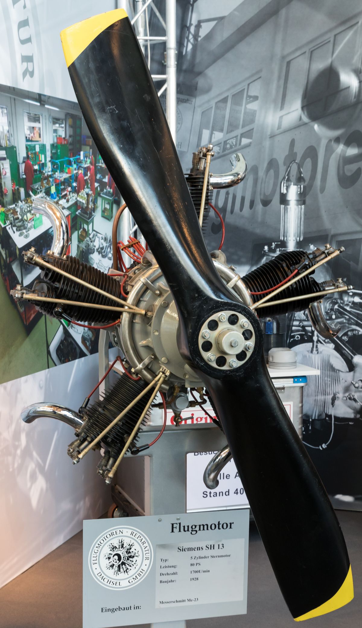
| Sh13 (A39, Wiki) | Sh14 (Wiki) | |
The Sh13 and Sh14, both released in 1928, were nearly identical to the previous models except for the cylinders, which were constructed differently and had a larger bore. The removable aluminum alloy cylinder heads were fastened by studs that were screwed into the cylinder. The rocker arms were supported independently on brackets formed by a stud that screwed into the cylinder head. The inlet port faced aft and the exhaust port was on the cylinder side. The bore was 105 mm (4.134"), the stroke 120 mm (4.724") and the compression ratio 5.3:1.
Siemens formed Brandenburgische Moternwerke G.m.b.H during 1936 to take over aircraft engine manufacture. The new company continued to build a few Siemens-Halske engines, along with new aircraft engine designs under the Siemens-Bramo brand.
Smith
 |
| 1911 Smith (A39) |
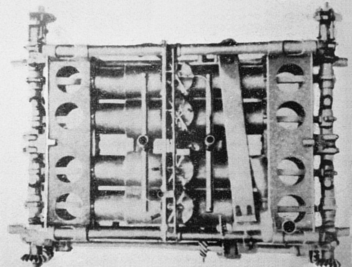
John William Smith (1871 ‑ ?) designed some of the first, if not the first, American air-cooled fixed radials. The first Smith engine, a radial six, appeared in Chicago during 1910. Between 1910 and WWI, Smith also designed aircraft (US 1,136,560A, US 1,396,974A) powered by his engine. The Smith engine featured a number of ground-breaking innovations, including an even number of cylinders in the same plane and a two-throw crankshaft with every other cylinder connected to a common crankpin via offset connecting rods (US 1,214,837A). The fuel/air mixture passed through the hollow crankshaft into the crankcase, then into the combustion chambers past valves located in the piston heads. A single exhaust valve in each cylinder head worked in conjunction with auxiliary exhaust ports in the cylinder barrel that were uncovered by the piston near the end of its stroke. The cylinders and pistons were cast iron. The two-piece crankcase, joined in the cylinder plane, captured the cylinders and two long fore-and-aft studs additionally secured each cylinder to the crankcase. The propeller hub included a puller nut.
 |
 |
| 140 hp Smith (A39) | |
The first Smith air-cooled radial 10, built in 1914, had a 4.500" (114.3 mm) bore, 5.500" (139.7 mm) stroke and displaced 874.74 in³ (14.334 l). Smith took the engine to England in January 1915, where he formed the British Static Motor Company in Birmingham with Charles Schofield as a partner. [An American Engine for the Vickers Gunbus in 1915]. Tests by the Royal Flying Corps showed an output of 140 hp at 1,250 rpm. It was installed and flown in a Vickers Gunbus (later FB5), where it became the highest-power air-cooled engine ever successfully flown. Despite the engine's successes and glowing reviews, Smith was unable to successfully manufacture it in the UK or France. Smith sold his share of the business, consisting mostly of the UK patent rights, to Richard Hammersley Heenan of Heenan & Froude Ltd in early 1916, and returned to the U.S. in August 1917. There he formed the Static Engine Company of Philadelphia, Pennsylvania, and accepted an order from the U. S. Army Signal Corps to construct two engines similar to the one delivered to England. With the same displacement and rated output, these engines weighed 372 lb (168 kg ) and had a 0.52 lb/hp/hr specific fuel consumption.
These Smith engines had steel cylinders and a forged-steel crankcase that was machined all over, which proved lighter than the aluminum crankcase design used in the preceding models. During tests in 1918, this design, with a 5.2:1 compression ratio, delivered 260 hp at 1,650 rpm when operated on commercial gasoline.
The particular feature common to all Smith designs was placing the six or ten cylinders in one plane about a two-throw crankshaft. Either three- or five-slipper connecting rods, with H-section shanks operated upon each crankpin. Shoes at the inner ends of these rods had a bearing on a spool supported upon the crankpin by roller bearings. Since the plane of the cylinders was midway between the crankpins, the rod axes were inclined relative to the plane of rotation. This unconventional arrangement achieved simplicity, reduction in overall length, and the elimination of heavy crankshaft counterweights.
The steel cylinders had integral circumferential cooling fins, and used concentric valves fitted co-axially in the head for operation by two push rods and rockers. A hole in the cylinder wall near the end of the stroke served as an auxiliary exhaust port. The engine was throttled by controlling the inlet valve closing time.
Another original Smith engine feature was the use of an impeller turning at crankshaft speed within the induction system (US 1,229,340A) that helped homogenize the air/fuel mixture; this was a precursor to the modern supercharger (US 1,329,811A). The mixture was then distributed to the cylinders by pipes that extended a short distance into the rotor housing so that liquid fuel could not drain into the lower cylinders.
 |
 |
 |
| 260hp Smith (A39) | 300hp Smith (A39) | |
The Smith engine was submitted for test by the Army Air Service Engineering Division at McCook Field, Ohio. With a 4.53125" (115.1 mm) bore, 6.250" (158.8 mm) stroke, 1,007.87 in³ (16.516 l) and 4.57:1 compression ratio, it produced 145 hp at 1,500 rpm from a 487 lb (221 kg) weight. Fuel consumption was 0.7 lb/hp/hr. This engine had a trunk-type cast-iron pistons with two rings above the piston pin. The inlet valve clear diameter 1.75" (44.45 mm), and the exhaust valve outside diameter, in which the intake valve seated, was 2.5" (63.50 mm). The lubricating system operated at about 2.5 psi pressure.
Under U.S. Army Contract, Smith built a larger experimental air-cooled radial 10 with a 5.500" (139.7 mm) bore, 6.500" (165.1 mm) stroke and 1,544.29 in³ (25.306 l) displacement. It was designed to deliver 300 hp at 1,600 rpm but ran very little.
S.P.A.
Matteo Ceirano and Michele Ansaldi founded The Societa Piemontese Automobili (S.P.A.) of Turin, Italy, in 1906. Aristide Faccioli (23 Dec 1848 ‑ 28 Jan 1920), an Italian mechanical engineer who had served as FIAT’s first technical director, came to S.P.A. around 1908, where he designed a series of aircraft and aircraft engines. [SPA-Faccioli Opposed-Piston Aircraft Engines]
 |
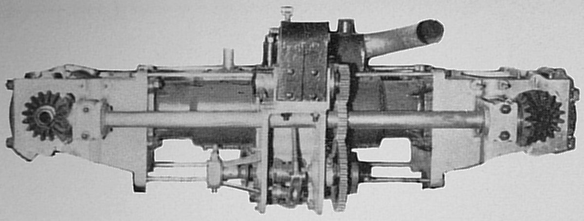
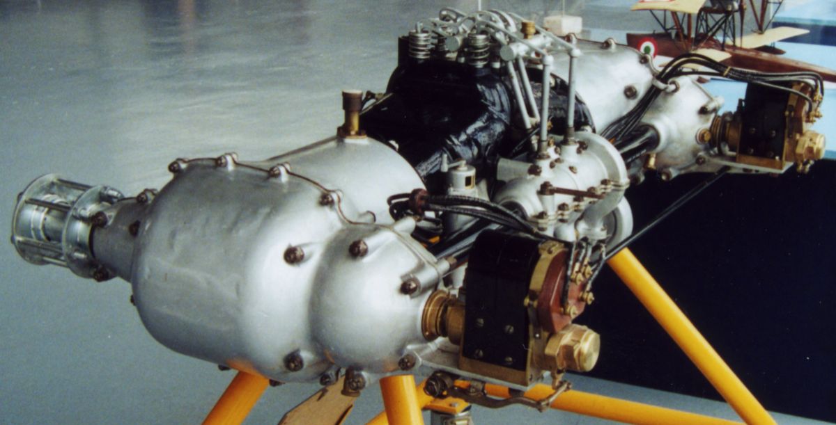
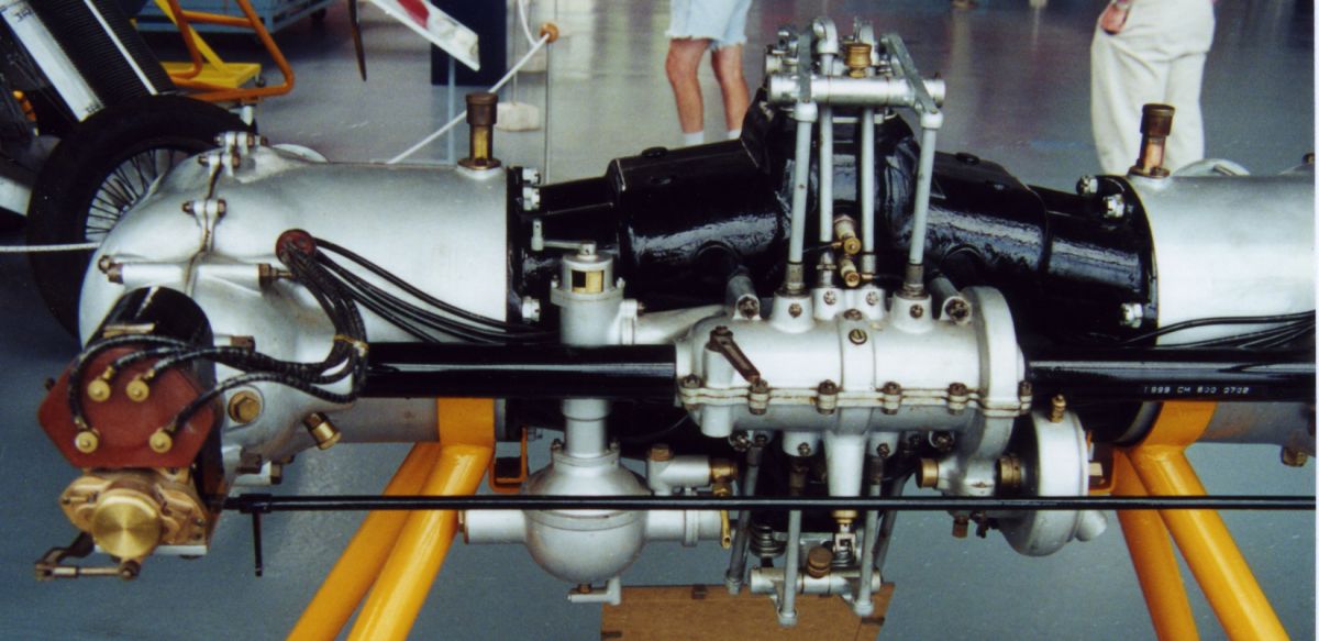
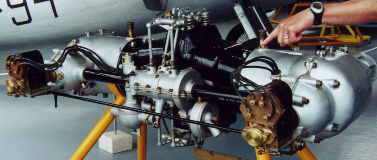
| SPA-Faccioli N.1 (OMP) |
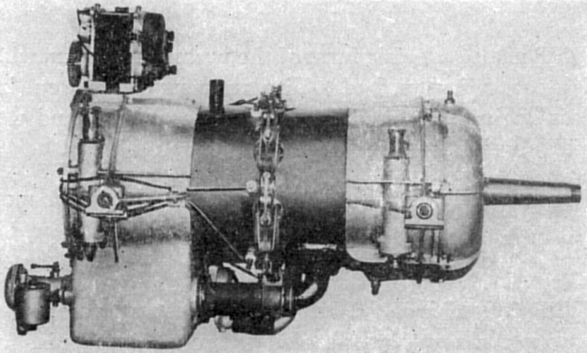
The SPA-Faccioli N.1 was a 1908 water-cooled opposed-piston horizontal four with crankshafts on either side, each driving a propeller. The counter-rotating propellers were phased so that one was horizontal when the other was vertical, a scheme intended to reduce propeller torque effects and vibration. The two crankshafts were synchronized via a cross shaft and bevel gears. A camshaft geared to the cross shaft operated inlet and exhaust valves at each cylinder’s center. A spark plug, also located in each cylinder center, provided ignition. With a 112 mm (4.409”) bore, 150 mm (5.906”) stroke and 11.822 l (721.45 in³) displacement, it developed 80 hp at 1,200 rpm and weighed 240 kg (529 lb). The N.1 was the first Italian-designed engine to successfully power an Italian-designed airplane (the Faccioli N.1) on 13 Jan 1909.
 |
 |
| SPA-Faccoili N.2 (OMP) | |
The SPA-Faccioli N.2 was a 1909 water-cooled opposed-piston horizontal single similar to the N.1. A magneto, driven by the cross shaft, supplied ignition. The intake was on the bottom and the exhaust on top. With a 100 mm (3.937”) bore, 130 mm (5.118”) stroke and 2.042 l (124.61 in³) displacement it produced 20 hp at 1,200 rpm, 25 hp at 1,500 rpm and weighed 48 kg (106 lb).
 |
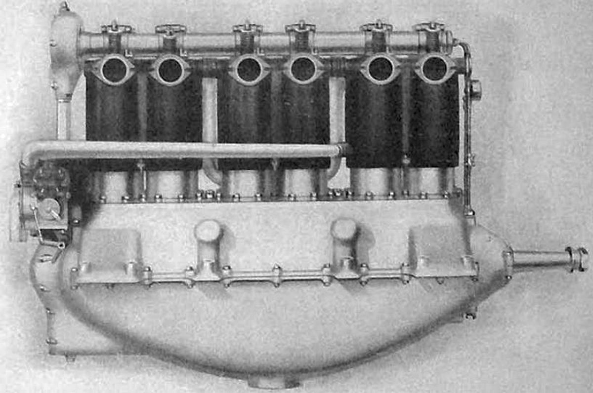
| SPA-Faccoili N.3 (OMP) |
The SPA-Faccioli N.3 was a 1911 water-cooled eight-cylinder engine sharing much with the previous engines. However, instead of directly opposed-pistons, the N.3 featured what amounted to twin horizontal 20° V-4s sharing four combustion chambers. Two magnetos driven by the cross shaft produced a single spark per cylinder pair. A camshaft, driven from the cross shaft, extended forward through the rhomboidal space between the cylinder banks and actuated one inlet and one exhaust valve per cylinder pair via push rods and rocker arms. An intake manifold at the engine front distributed the fuel/air mixture on the engine right while the exhaust ports were on the left. With a 75 mm (2.953”) bore, 150 mm (5.906”) stroke and 5.301 l (323.51 in³) displacement, it produced 40 hp at 1,400 rpm, 50 hp at 1,600 rpm and weighed 90 kg (198 lb).
 |
 |
 |
 |
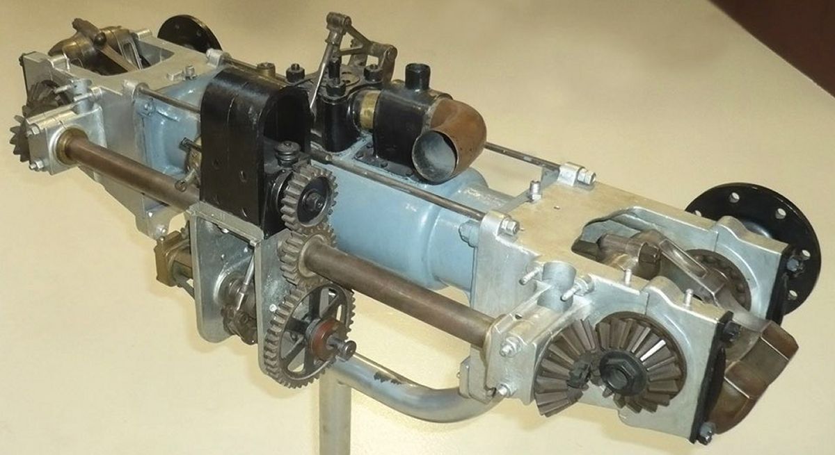
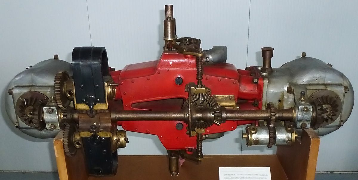
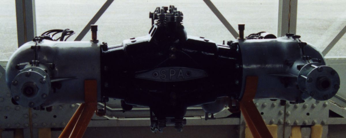
| SPA-Faccoili N.4 (Author) |
The SPA-Faccioli N.4 was a refined and enlarged N.3 from late 1911 or early 1912. Two magnetos, one at each crankshaft aft end, provided dual ignition. The cross shaft now carried the cams, which operated the valves via push rods and rocker arms. The intake manifold was now at the engine left aft and the exhaust ports were on the right. With a 95 mm (3.740”) bore, 150 mm (5.906”) stroke and 8.506 l (519.06 in³) displacement, it produced 80 hp at 1,200 rpm , 90 hp at 1,600 rpm and weighed 200 kg (441 lb). It was 813 mm (32”) long, 1,372 mm (54”) wide and 559 mm (22”) high.
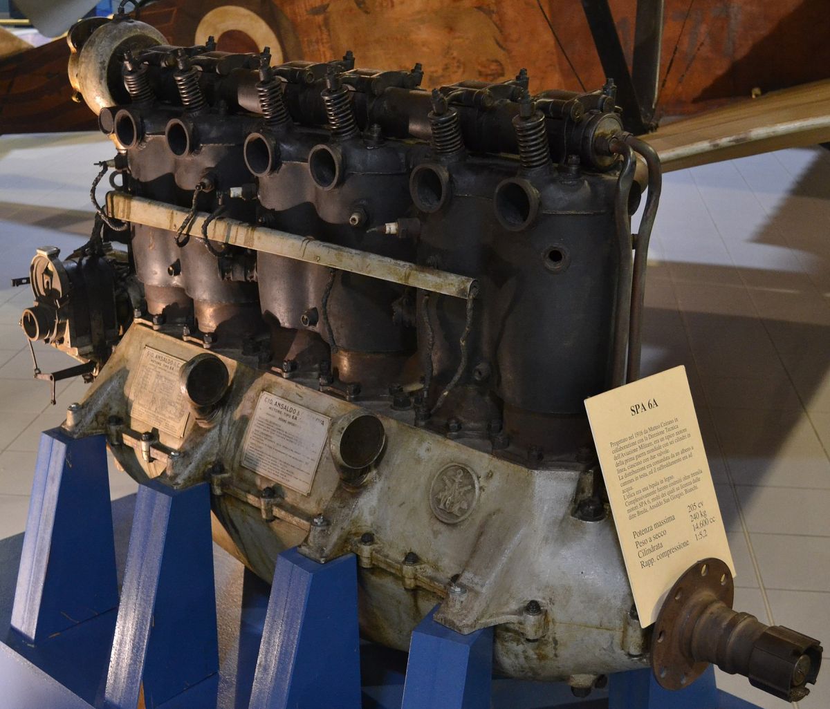
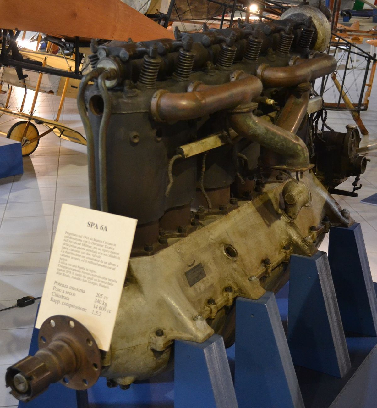
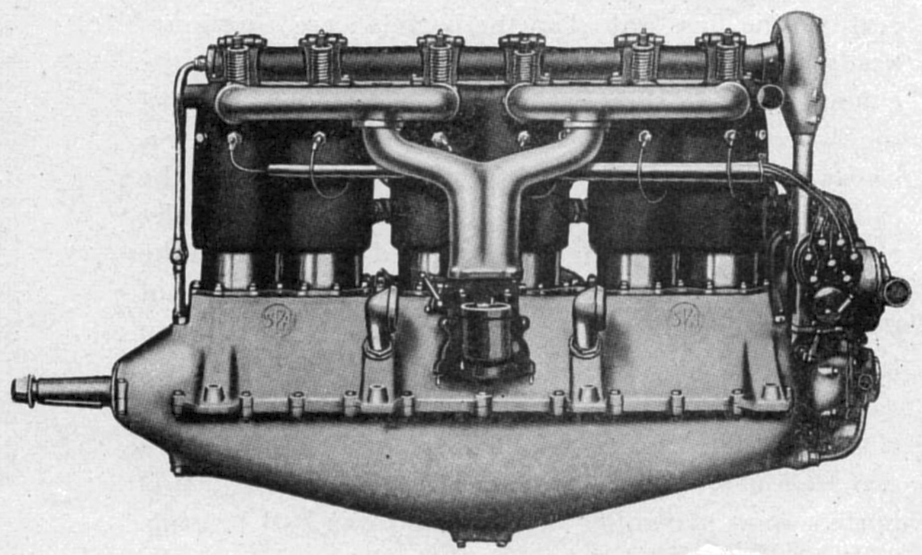
In 1915, S.P.A. built a ten-cylinder radial. In 1916, the plant was enlarged to manufacture the S.P.A. 6-A. This engine also has been built by Ansaldo San Giorgio, Breda, Talomona, and the Industrie Mecchaniche e Ferroviarie of Arezzo. The 6-A was built in three versions: Normal, Semi-Super-Compressed, and the Super-Compressed.
The 6-A Normal was a water-cooled vertical six with a 135 mm (5.315") bore, 170 mm (6.693") stroke and 14.600 l (890.96 in³) displacement rated 150 hp at 1,600 rpm and weighing 255 kg (562 lb). Fuel and oil consumptions were 0.473 and 0.033 lb/hp/hr. It was fitted either with two single Zenith carburetors or one Zenith type 55-DC duplex carburetor. The dry-sump pressure-fed lubrication system circulated the oil with gear pumps. Two H-2 or EM-6 Marelli magnetos supplied dual ignition, and a double inlet centrifugal pump circulated the water. The steel cylinders were arranged in pairs, with mounting flanges welded together, and encased by a common welded-on three-part water jacket. The overhead camshaft was driven by bevel gears from a vertical drive shaft. Single inlet and exhaust valves in each cylinder were inclined to the vertical axis. Each valve had a 55.6 mm (2.1875") clear diameter, a 11.9 mm (0.46875") lift and 45° seats. Inlet valves opened 8° late and closed 50° late; exhaust valves opened 62° early and closed 14° late. The six-throw crankshaft was supported by four plain hearings, and the H-section connecting rods had four-bolt caps. Modified hour-glass aluminum alloy pistons were ribbed underneath the head and fitted with two compression rings above the pin and one oil scraper ring below.
The 6-A Super-Compressed engine had a 137 mm (5.394") bore, 170 mm (6.693") stroke and 15.036 l (917.55 in³) displacement. It was rated 200 hp at 1,600 rpm but developed 235 hp at 1,750 rpm. It was identical to the 6-A Normal except for a 2 mm (0.0787") bore increase, higher compression and tubular-shank connecting rods.
 |
 |
 |
 |
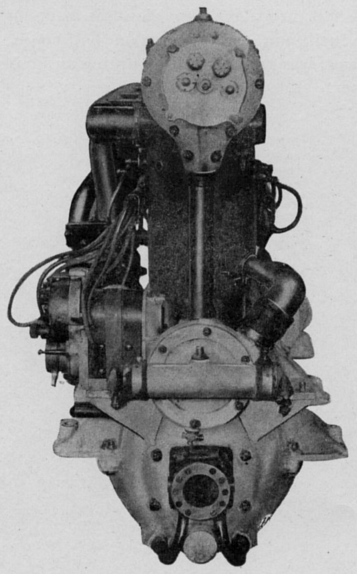 |
| S.P.A. 6-A Normal (Public Domain, Wiki, Wiki, A39, A39) | ||||
The 6-2-A was a water-cooled vertical six with a 140 mm (5.512") bore, 180 mm (7.087") stroke and 16.625 l (1,014.5 in³) displacement that was rated 250 hp but delivered 270 hp at 1,700 rpm. It weighed 270 kg (595 lb).
The 1-A was a water-cooled 45° V-16 with a 135 mm (5.315") bore, 170 mm (6.693") stroke, 38.934 l (2,375.88 in³) displacement and 5.0:1 compression ratio. It was rated 500 hp at 1,500 rpm and weighed 579 kg (1,276 lb). The cylinders and pistons were practically identical to those in the 6-A Normal. The eight-throw crankshaft had two throws 180° apart between each main bearing. The articulated connecting rods had master rods four-bolt caps. Four carburetors were fitted.
The 2-A, a water-cooled vertical eight using the same cylinders as the 6-A Super-Compressed, had a 137 mm (5.394") bore, 170 mm (6.693") stroke, 20.048 l (1,223.40 in³) displacement and 5.3:1 compression ratio. It was rated 300 hp at 1,600 rpm.
Sturtevant
Benjamin Franklin Sturtevant (1833-1890) founded the Boston-based B.F. Sturdevant Company in 1860 to produce wooden shoemaking pegs. The manufacturing process created volumes of airborne sawdust, so Sturdevant invented an industrial fan to remove the dust. By 1866, more than 50 workers exclusively made fans and blowers. In 1869, the “Sturdevant System” of hot blast indoor heating using ductwork to distribute warm air was taking hold. Further work for the U.S. Navy ventilating ship hulls led to mechanical draft fans that improved boiler fuel efficiency to the extent that back-up sail systems were retired. In 1903, a new plant was built at Hyde Park to manufacture equipment for what had become the world's largest electric fan producer. In 1906, Sturdevant installed the first industrial air conditioning system.
When B.F. Sturtevant died, his son-in-law, Eugene Foss, took over the company. With its background in heating, ventilation and air conditioning, it seems surprising that the Sturdevant Company would became an aircraft engine manufacturer, but Foss’s son, Noble became interested in aviation. In 1911, with the help of engine developers Harold N. Bliss and George Abel, Sturdevant began building water-cooled engines and later aircraft. This continued until 1918, when like many other post-WWI engine makers, Sturtevant succumbed to the glut of war-surplus Curtiss OX-5s and Liberty 12s. The foundry moved to Framingham, Massachusetts and continued providing castings to Pratt & Whitney during the 1920s and 1930s. During WWII, the Sturtevant Company provided ignition coils for aircraft engines and ventilation fans for aircraft heaters. [Wikipedia, Sturtevant Fan Company]
 |
| D-4 (AEE) |
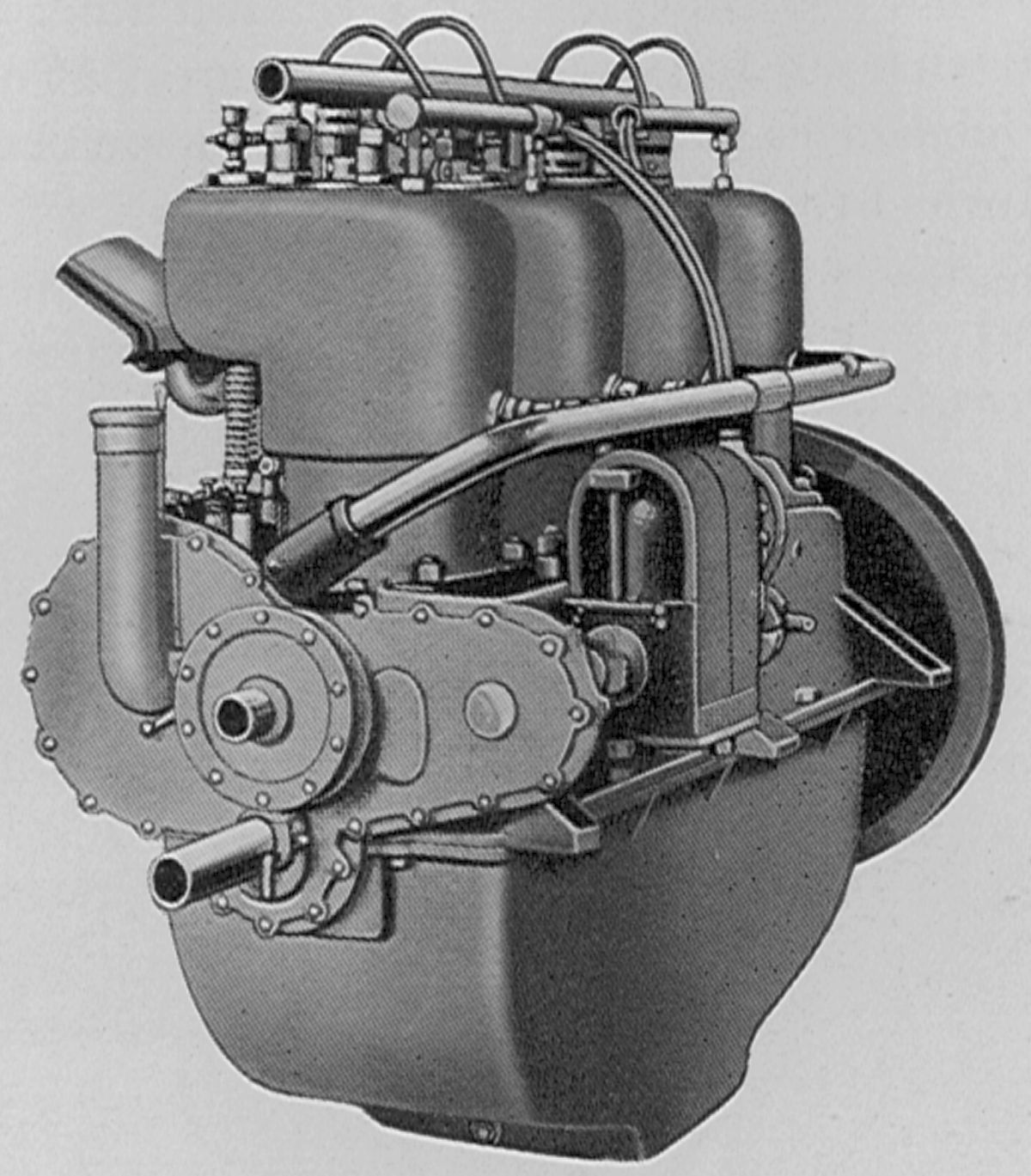
The D-4, Sturtevant’s first aircraft engine, was an inline four with 4.500" (114.3 mm) bore and stroke that displaced 286.28 in³ (4.691 l). It developed 48 hp at 1,300 rpm, 55 hp at 1,700 rpm and weighed 220 lb (99 kg). Fuel and oil consumptions were 0.57and 0.058 lb/hp/hr. Separate L-head cylinders with integral water jackets were cast from semi-steel. The crankshaft ran in five plain hearings, and the connecting rods had H-section shanks. The cast iron pistons were fitted with three rings. Mea magnetos furnished ignition and a Zenith carburetor the mixture. A gear pump maintained 20 psi oil pressure. The D-4 was 38.5" (978 mm) long, 19.875" (505 mm) wide and 23.625" (600 mm ) high.
 |
 |
 |
| D-6 (AEE) | D-6 (NASM (CC0)) | |
The D-6, which used cylinders similar to the D-4 with identical dimensions, displaced 429.42 in³ (7.037 l), was rated 73 hp at 1,300 rpm and produced 86 hp at 1,700 rpm. It weighed 320 lb (145 kg), was 51.625" (1,300 mm) long, 19.875" (505 mm) wide and 25" (635 mm) high.
 |
| E-4 (AEE) |
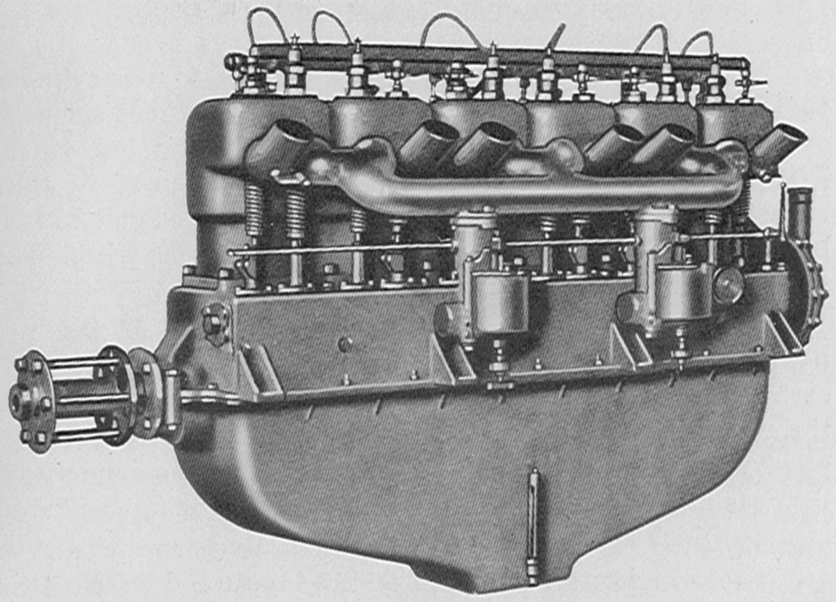
The E-4, a 1915 vertical four with a 4.500" (114.3 mm) bore, 6.000" (152.4 mm) stroke and 381.70 in³ (6.255 l) displacement, was rated l00 hp at 1,800 rpm and weighed 420 lb (190.5 kg), including flywheel. Fuel and oil consumptions were 0.552 and 0.05 lb/hp/hr. The spur-geared propeller shaft was mounted on two ball bearings and ran at half crankshaft speed. A Zenith carburetor bolted to the lower crankcase half received heated air through the oil cooler. Either a fuel or air pump was supplied with the engine. A rotary pump took oil from the sump, which included an oil cooler, and circulated it at 50 psi. The T-head cylinders were cast in one block from semi-steel with jackets integral. Four valves per cylinder were operated directly through tappets from a camshaft on each crankcase side. The five-main-bearing crankshaft had manganese bronze bearing caps held in place by long through bolts that also secured the cylinders. The connecting rods had H-section shanks. The pistons were made from cast iron and fitted with three rings. A Bosch magneto furnished ignition.
The 1915 Model 5 was a 5:3-geared 90° V-8 with a 4.000" (101.6 mm) bore, 5.500" (139.7 mm) stroke and 552.92 in³ (9.061 l) displacement that was rated 140 hp at 2,000 rpm and weighed 580 lb (263 kg). Fuel and oil consumptions were 0.51 and 0.032 lb/hp/hr. The L-head cylinders were cast in pairs from semi-steel with integral water jackets. The camshaft, situated in the Vee, operated each cylinder's single inlet and single exhaust valve through tappets. The three-main-bearing crankshaft had side-by-side H-section connecting attached to semi-steel pistons.
 |
 |
 |
 |
 |
 |
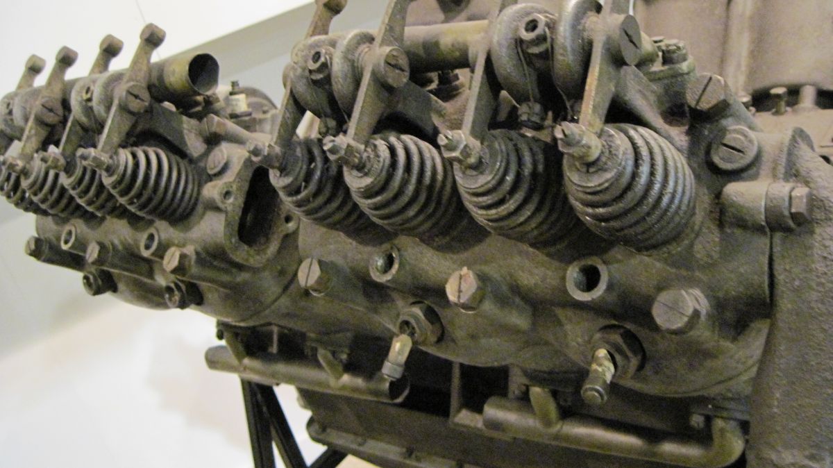 |
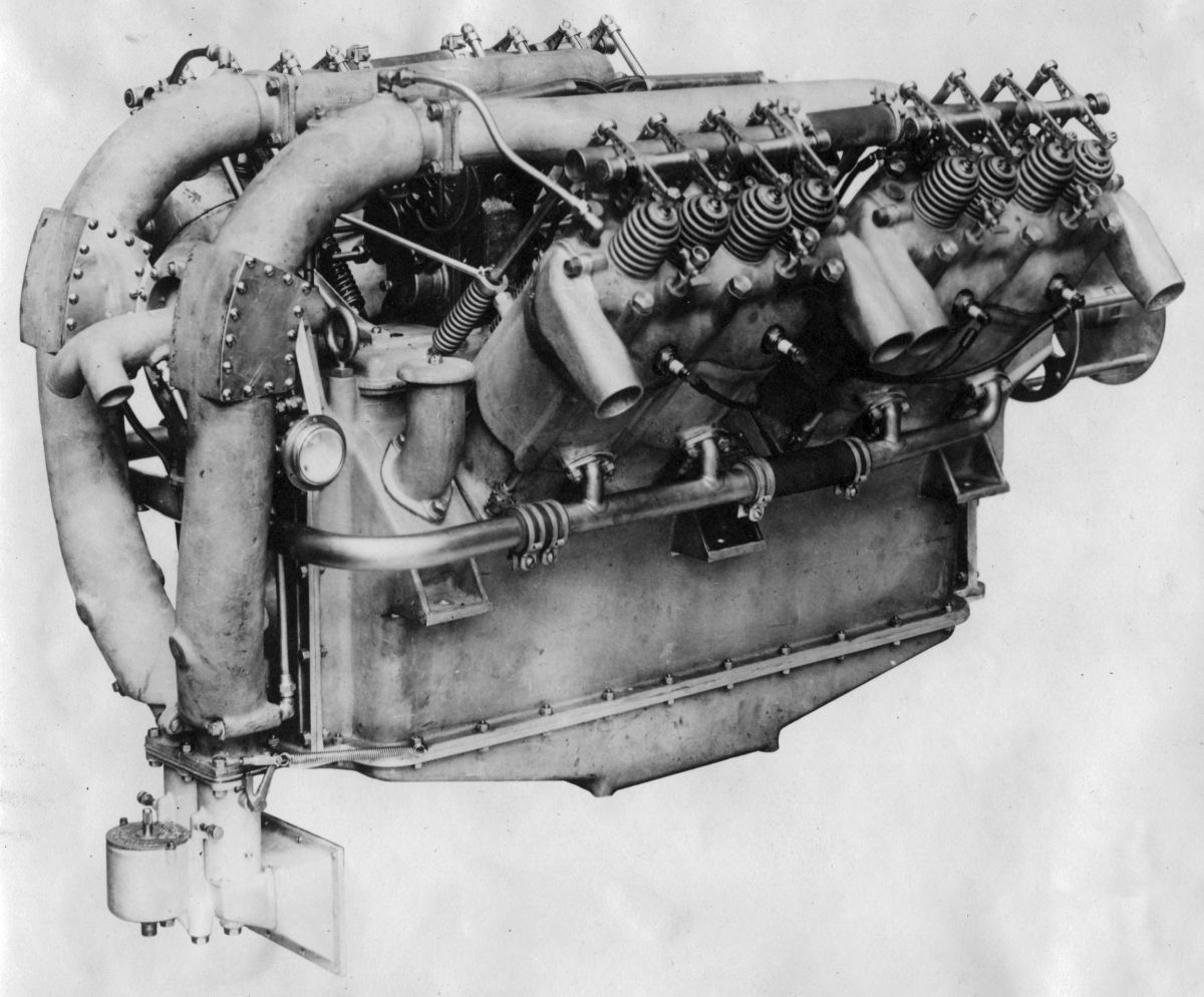
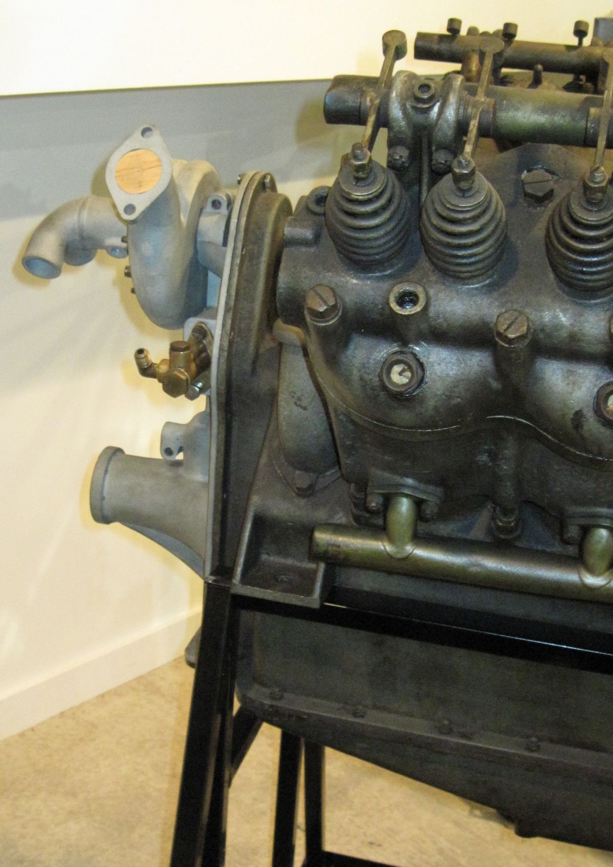
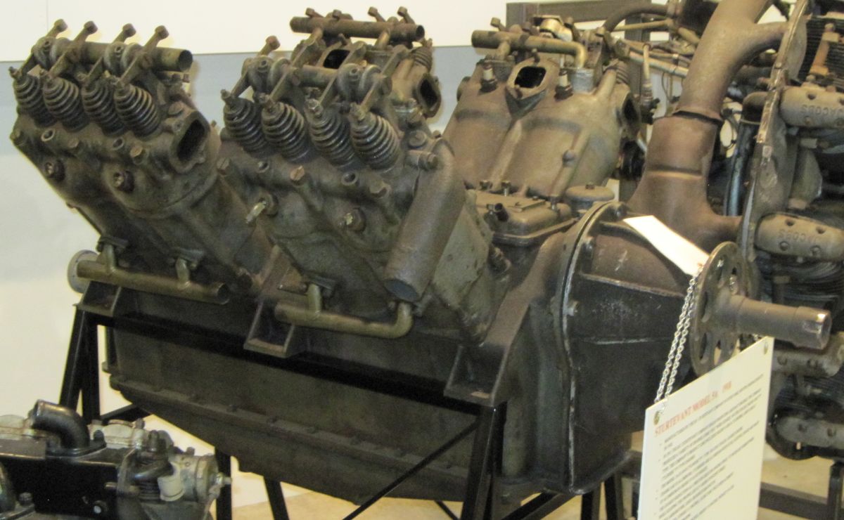
| 5A (Author) | 5A (AEHS) | 5A (AEE) | 5A (Author) | |||
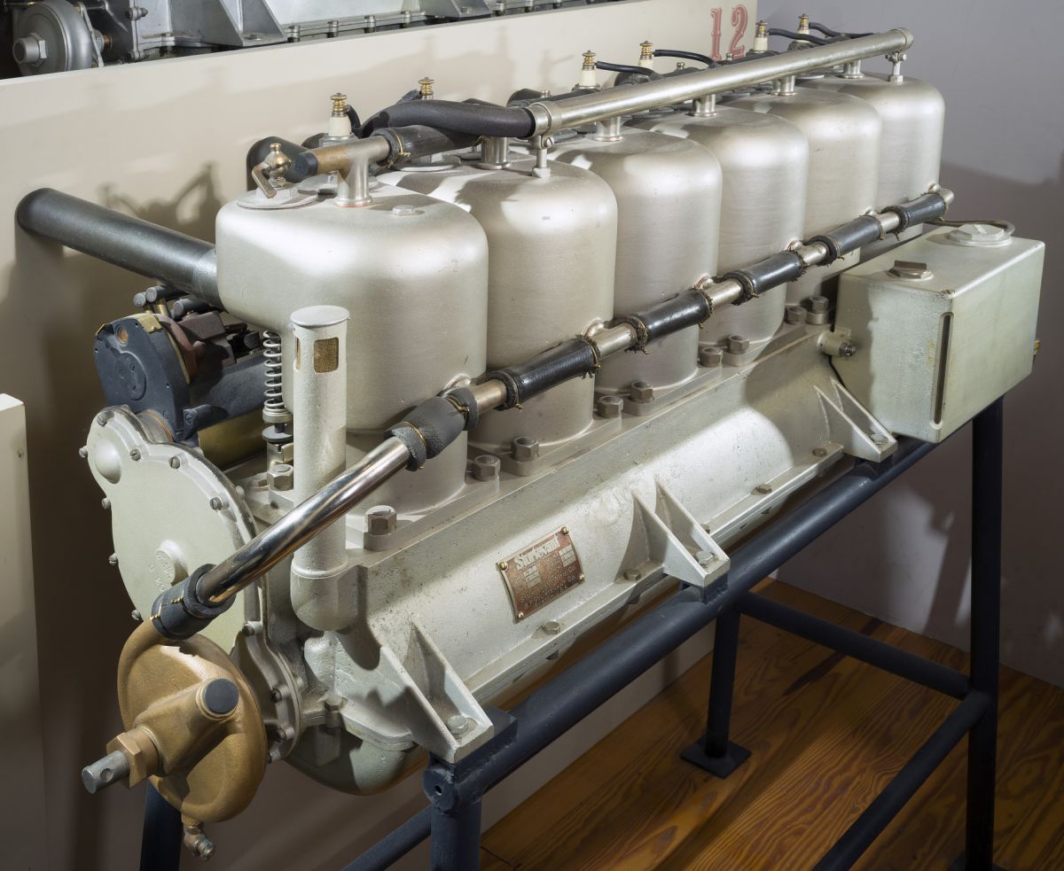
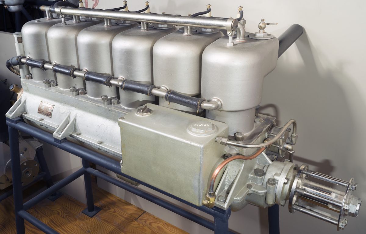
The Model 5A retained the Model 5's cylinder dimensions and displacement, but could be had with either direct or 5:3-geared propeller drive. It was rated 140 hp at 2,000 rpm and weighed 514 lb (233 kg), not including the 36 lb (16 kg) water content. It was 50" (1,270 mm) long, 34" (864 mm) wide and 35" (889 mm) high. A duplex Zenith carburetor furnished the mixture, and a gear pump provided pressure lubrication. The cylinders were cast in pairs from aluminum alloy and fitted with steel liners. The detachable aluminum alloy cylinder heads were also cast in pairs. The camshaft, situated in the Vee, operated the vertical single inlet and single exhaust valves in each cylinder head through push rods and rocker arms. Inlet valves opened 15° early and closed 45° late; exhaust valves opened 45° early and closed 10° late. The four-throw three-main-hearing crankshaft was supported by separate bearing caps. The H-section connecting rods ran side-by-side upon the crankpins. The deeply-ribbed aluminum alloy pistons were and fitted with two rings. Cooling water was circulated by a centrifugal pump, and either Dixie or Bosch magnetos supplied dual ignition.
 |
 |
 |
| Normal Induction Layout | Overhead Carbs | |
The Model 5A-4 1/2 was a 5:3-geared 90° V-8 that closely resembled the 5A, but with a 4.500" (114.3 mm) bore, 5.500" (139.7 mm) stroke and 699.79 in³ (11.468 l) displacement. It was rated 210 hp at 2,250 rpm but could deliver 240 hp. Dry weight was 480 lb (218 kg) and the cooling water weighed 35 lb (16 kg). Fuel and oil consumptions were 0.55 1b and 0.038 lb/hp/hr. Duplex Zenith carburetors and two eight-cylinder Dixie magnetos were fitted.
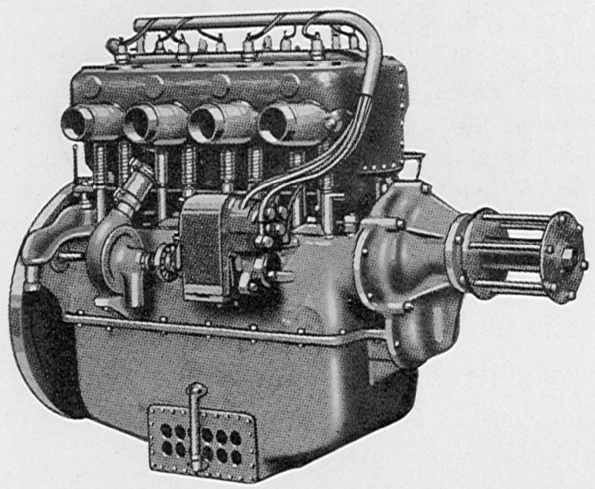
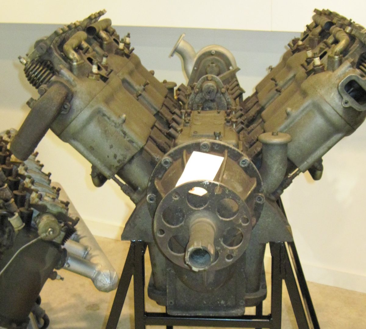
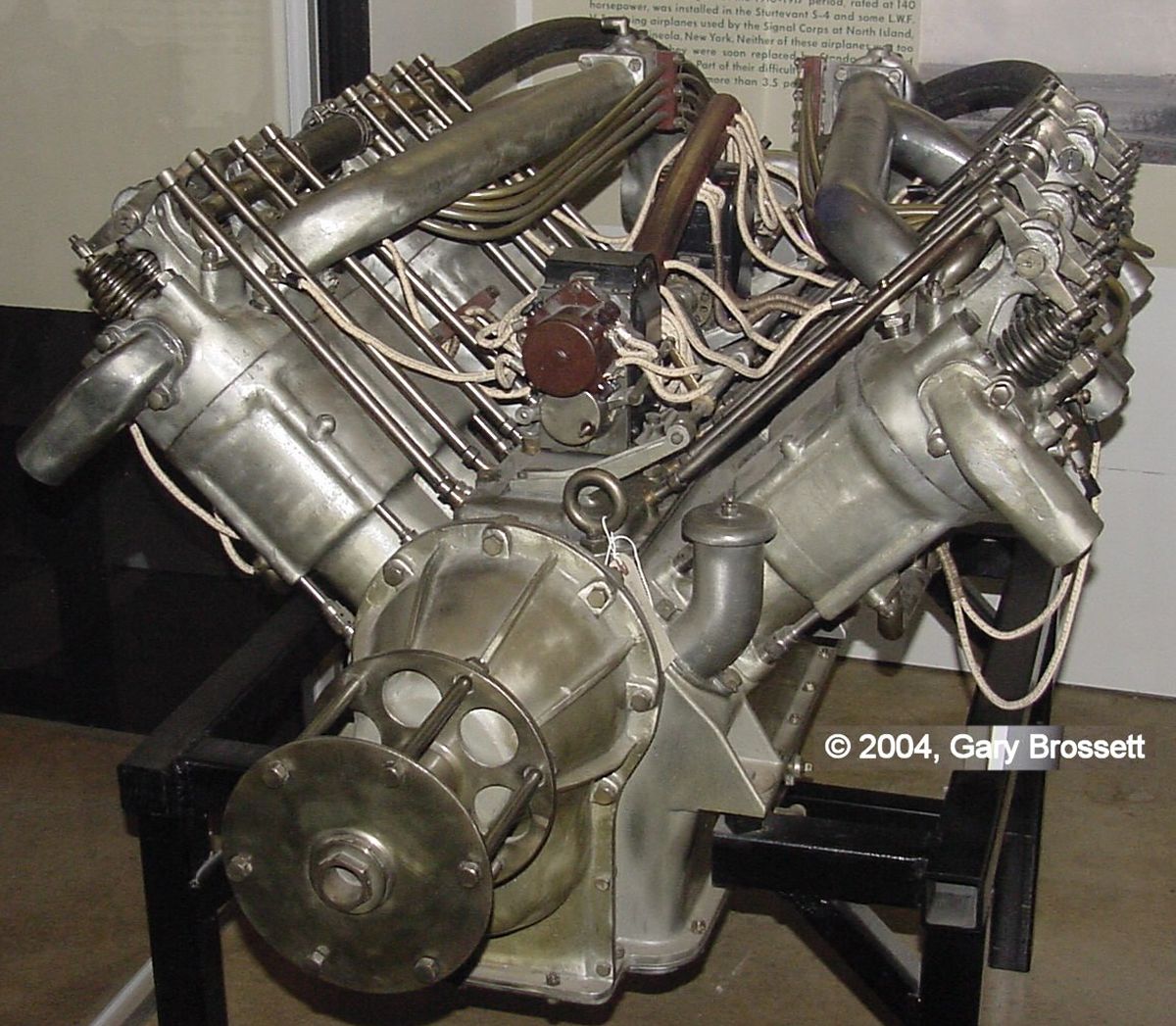
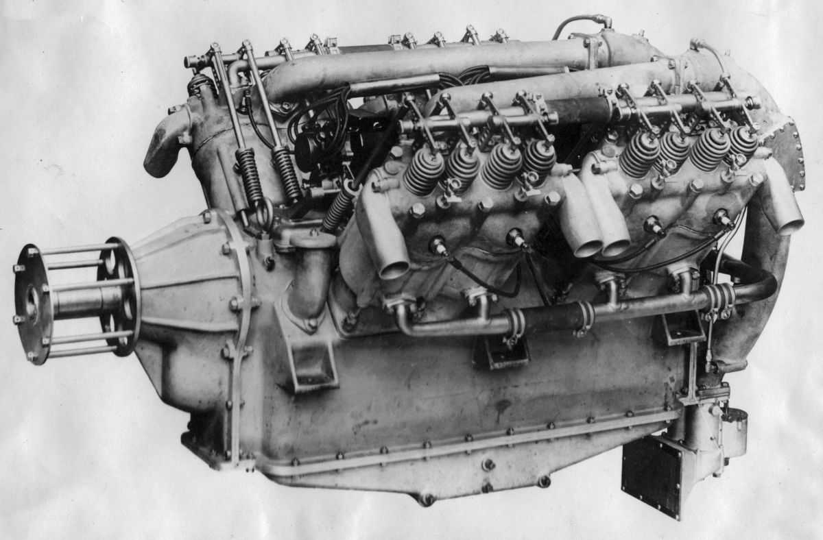
The Model 7 was a 60° V-12 with the same cylinder dimensions and construction as the Model 5A-4 1/2. Displacing 1,049.68 in³ (17.201 l), it produced 300 hp.
Sunbeam
John Marston, founder of John Marston and Sons, Ltd., a bicycle manufacturer, registered the moniker "Sunbeam" in 1888. Marston began producing motor cars in 1901, and formed The Sunbeam Motor Car Company, Ltd., of Wolverhampton, England in 1905. The Breton automobile and engine designer, Louis Coatalen, joined Sunbeam in 1909 as Chief Engineer. In 1912, Sunbeam began designing an aircraft engine.
The Sunbeam 110 of 1913 evolved from successful Coatalen auto racing engine designs. A 2.0:1-geared water-cooled 90° L-head V-8 with an 80 mm (3.150”) stroke, 150 mm (5.906”) stroke and 6.032 l (368.09 in³) displacement variously produced 100, 110 and 120 hp. The propeller shaft was driven from the camshaft.
 |
| Crusader (A39) |
The Crusader, a more refined late-1914 2.0:1-geared water-cooled 90° V-8 with a 90 mm (3.543") bore, 150 mm (5.906") stroke and 7.634 l (465.86 in³) displacement was rated 150 hp at 2,000 rpm but was also available in a 135 hp version. The propeller was driven from the camshaft. This engine was named Crusader in 1917 after production had stopped. Fuel and oil consumptions were 0.49 and 0.032 lb/hp/hr. Weight was 218 kg (485 lb). The L-head cylinders were cast en-bloc from iron in groups of four and had electrolytically deposited copper water jackets. The pistons were machined from solid aluminum alloy with the piston pin supported by the piston head. Opposite cylinder rows were staggered, permitting side-by-side connecting rods on each crankpin. The crankshaft was carried in five plain bearings, and the propeller shaft in ball bearings. Claudel-Hobson carburetors were attached to four-cylinder inlet manifolds placed on the outside. A gear pump provide pressure lubrication and one magneto furnished ignition.
The Zulu, developed during 1915 and initially called the Sunbeam 160, was a 24:13-geared water-cooled upright L-head 60° V-8 with a 100 mm (3.937") bore, 150 mm (5.906”) stroke that displaced 9.425 l (575.14 in³). Producing 160 hp at 2,000 rpm, 75 were built.
 |
| Mohawk (UKNA) |
The Sunbeam 200 hp was a water-cooled 60° V-12 used Sunbeam 110 hp cylinders with an 80 mm (3.150”) stroke, 150 mm (5.906”) stroke and 9.048 l (552.13 in³) displacement. When the Royal Navy required more power, Coatalen designed a three-cylinder casting with one carburetor supplying each cylinder group; two magnetos mounted crosswise at the anti-propeller engine end furnished ignition. This Sunbeam 225 hp, with its 90 mm (3.543") bore, 150 mm (5.906") stroke and 11.451 l (698.79 in³) displacement was rated 225 hp at 2,000 rpm and weighed (329 kg) 725 lb. As before, the propeller shaft was driven from the camshaft at 1/2 crankshaft speed. The Sunbeam 225 hp was renamed Mohawk in 1917; 287 were delivered.
The 1916 Gurkha was developed as a Mohawk replacement. As 2.0:1-spur-geared water-cooled upright L-head 60° V-12 with a 100 mm (3.937") bore, 150 mm (5.906") stroke and 14.137 l (862.70 in³) displacement, it produced 240 hp at 2,000 rpm; 83 were delivered.
The 1916 Cossack I [Wikipedia] was a 2.0:1-geared water-cooled dual-overhead-camshaft four-valve-per-cylinder 60° V-12 with a 110 mm (4.331") bore, 160 mm (6.299") and 14.825 l (904.69 in³) displacement that produced 310 hp at 2,000 rpm. Two magnetos provided ignition.
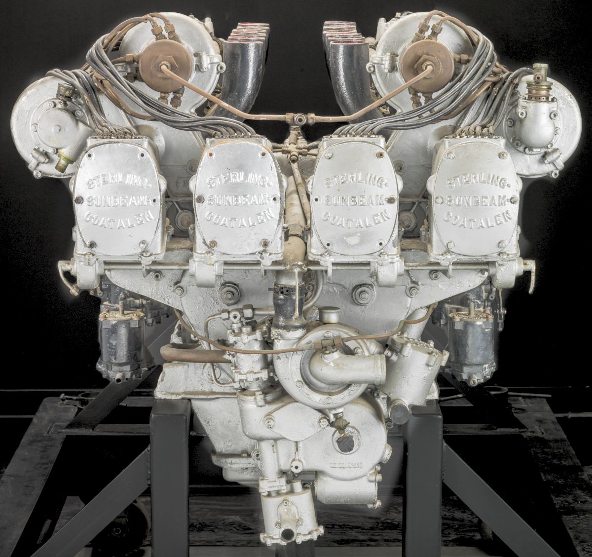
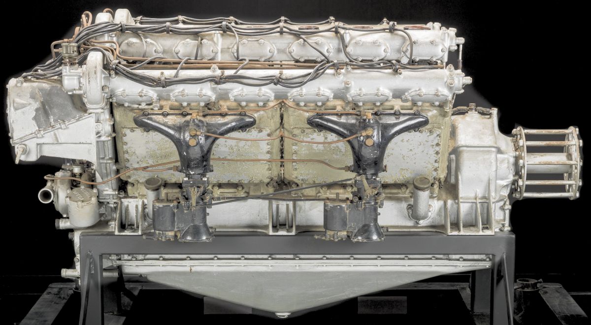
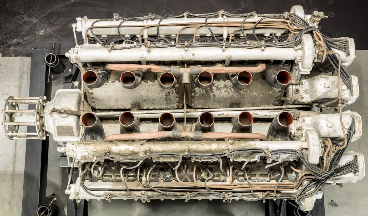
The Cossack II was a refined Cossack I with a 110 mm (4.331") bore, 160 mm (6.299") stroke, 5.0:1 compression ratio and 18.246 l (1,113.46 in³) displacement that produced 320 hp at 2,000 rpm. The Cossack II was 1,569 mm (62") long, 960 mm (38") wide, 988 mm (39") high and weighed 623 kg (1,373 lb). Four magnetos furnished ignition, four Claudel-Hobson CZS 42 carburetors provided the mixture, and a pressure-fed dry-sump lubrication system kept things oiled. The Cossack II was built under license in the U.S. by the Stirling Engine Company of Buffalo, New York.
 |
 |
 |
 |
 |
 |
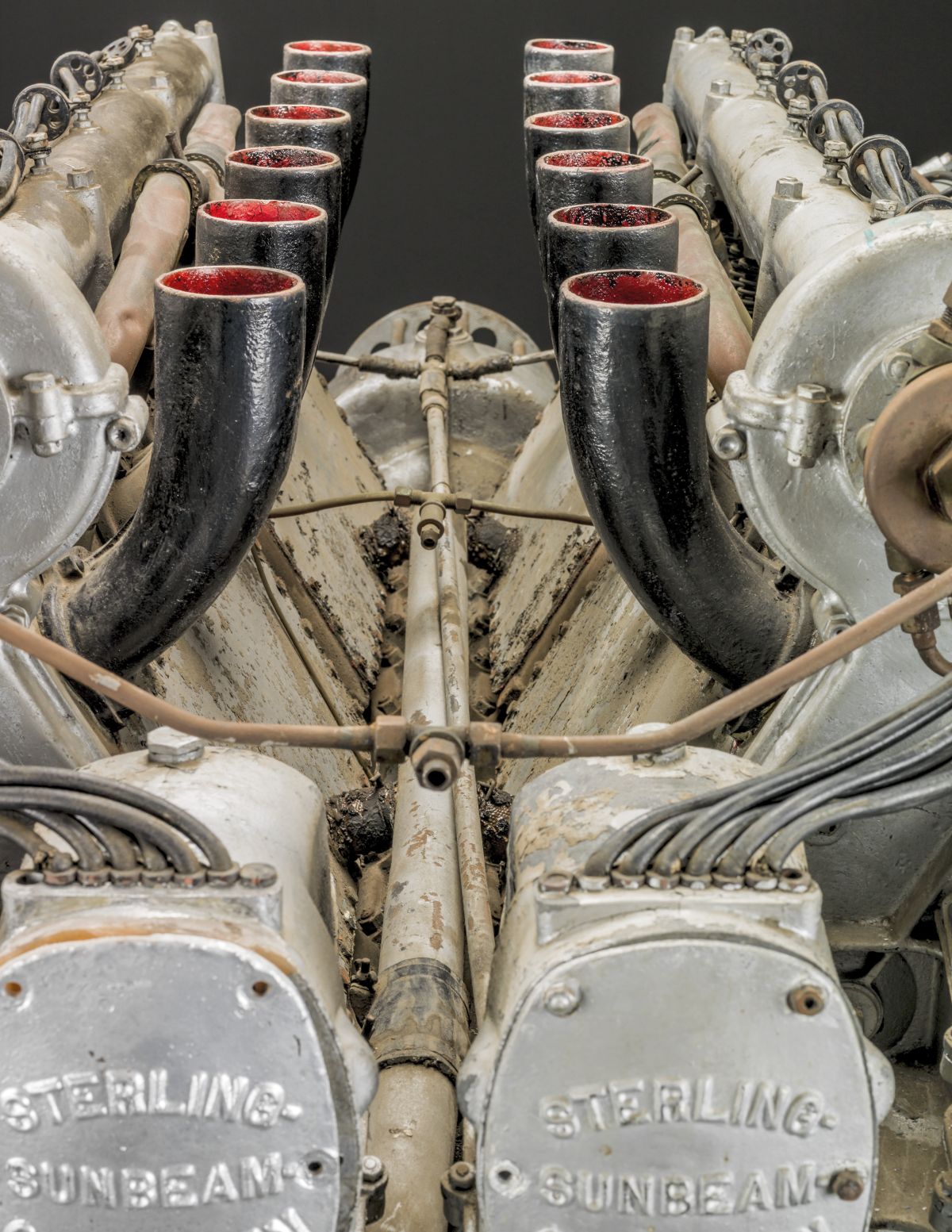 |
| Stirling Sunbeam Cossackk II (Wiki) | ||||||
The Cossack III, intended for Royal Navy airships that were cancelled, had a flywheel, hand or air starter, engine-mounted controls, a speed governor, and water-cooled exhausts. Only 14 Cossack IIIs were built, while 350 Cossack I and IIs were built.
The 1916 Amazon, a half-Cossack, was a 27:17-geared water-cooled dual-overhead-camshaft four-valve-per-cylinder vertical six with a 110 mm (4.331") bore, 160 mm (6.299") stroke, 5.0:1 compression ratio and 9.123 l (556.73 in³) displacement that produced 160 hp at 2,000 rpm. The Mk.I Amazon, a flight engine, had two magnetos while the Mk.II Amazon, a non-flight engine, had one. Two 42 mm Claudel-Hobson B.Z.S. carburetors were provided. The Amazon retained iron cylinder blocks cast in threes. The Amazon was 1,430 mm (56.29") long, 485 mm (19.1") wide, 980 mm (38.6") high and weighed 262 kg (578 lb); 77 were delivered.
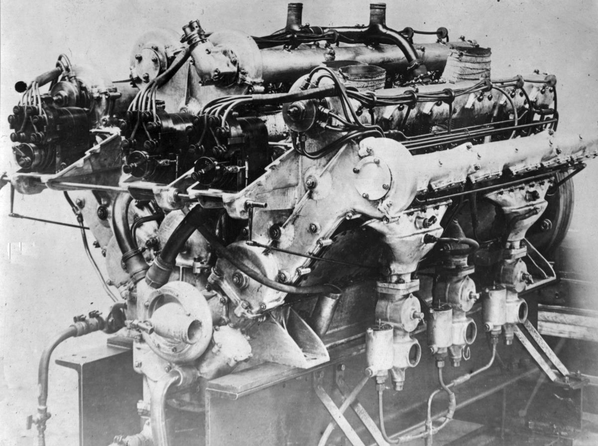 |
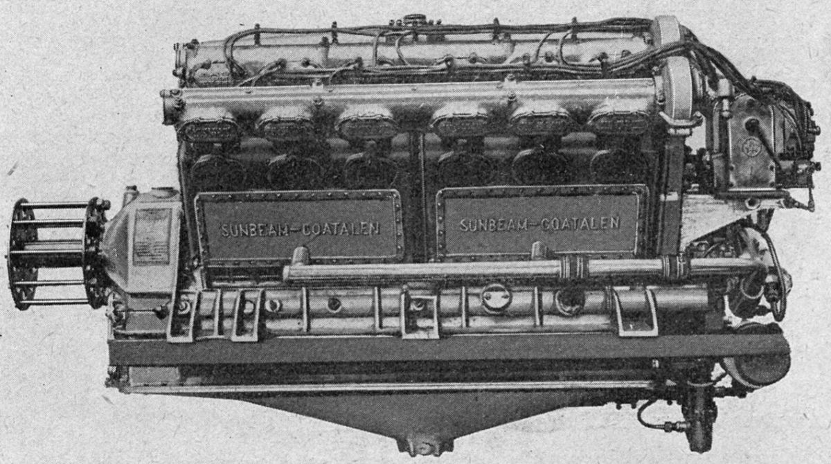
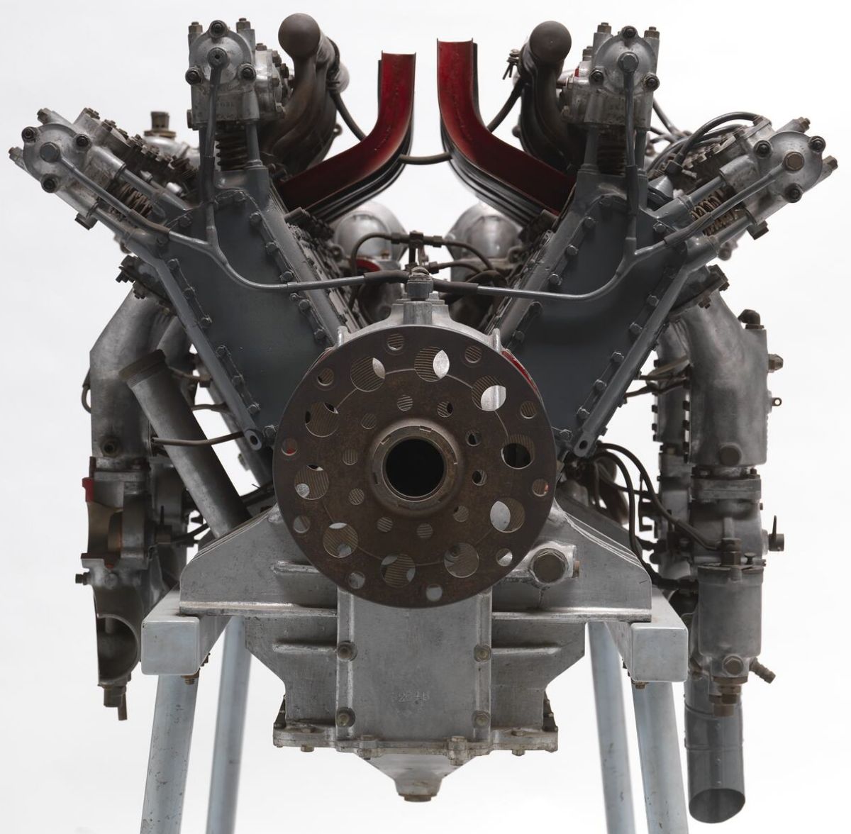
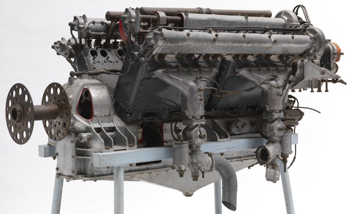
| Viking (NARA) |
The Viking was a 2.0:1-geared water-cooled W-18 built using Cossack and Amazon parts. With its 110 mm (4.331") bore, 160 mm (6.299") stroke, 5.0:1 compression ratio and 27.370 l (1,670.19 in³) displacement, it was rated 450 hp but produced 475 hp and weighed 648.64 kg (1,430 lb). It was 1,600 mm (63") long, 1,181 mm (46.5") wide and 1,130 mm (44.5") high; nine were produced.
The Saracen was a revised Amazon with 2.0:1 propeller reduction gearing, cast aluminum alloy blocks and 122 mm (4.803”) bores. Displacing 11.222 l (684.83 in ³), it produced 200 hp at 2,000 rpm and weighed 240 kg (530 lb). It was 1,428 mm (56.29") long, 485 mm (19.09") wide and 980 mm (38.58") high. Only prototypes were built.
 |
| Matabele (Wiki) |
The Matabele was a 27:17-geared water-cooled 60° V-12 that used Saracen cylinder blocks and displaced 22.445 l (1,369.65 in³). Rated 420 hp at 2,000 rpm, it weighed 454 kg (1,000 lb). Carburetors were located in the Vee. The Matabele I, an aircraft version, had four magnetos that provided dual ignition. The Matabele II, intended for non-aviation use, had single ignition from two magnetos. A pair of Matabele I engines were salvaged from the Maple Leaf VII power boat and fitted in tandem within the chassis of the Sunbeam 1000 hp racing car, which on 29 Mar 1927 was the first automobile to exceed 200 mph.
The 1916 Afridi [Wikipedia] was a 2.0:1-geared water-cooled 60° V-12 intended as a smaller Cossack companion. With a 92 mm (3.622”) bore, 135 mm (5.315”) stroke, 10.769 l (657.17 in³) displacement and 5.0:1 compression ratio, it produced 200 hp at 2,000 rpm and weighed 338 kg (745 lb). It was 1,420 mm (55.9") long, 851 mm (33.5") wide and 861 mm (33.9") high. The iron cylinders were cast in groups of three. Four valves per cylinder were actuated via spur-gear-driven dual overhead camshafts. Two Claudel-Hobson carburetors placed outside the Vee provided the fuel/air mixture, and four six-cylinder magnetos furnished dual ignition. Sunbeam delivered 299 Afridis, 100 of which were converted to Sunbeam Maori models. Afridi design concepts formed the basis of several other model lines.
 |
 |
 |
 |
 |
| Maori I (Wiki) | ||||
The 1917 Maori Mk.I, converted from Afridis, was a 2.0:1-geared water-cooled 60° V-12 with a 100 mm (3.937”) bore, 135 mm (5.315”) stroke, 12.723 l (776.43 in³) displacement and 5.3:1 compression ratio that produced 250 hp at 2,000 rpm and weighed 338 kg (745 lb). The four valves per cylinder were actuated via spur-gear-driven dual overhead camshafts. Four 38 mm Claudel-Hobson CZS carburetors placed outside the Vee provided the fuel/air mixture. The exhausts were inside the Vee. Four six-cylinder magnetos furnished dual ignition.
The Maori Mk.II, newly-built designs with the same characteristics as the Maori I, delivered 260 hp at 2,000 rpm. This design was 1,613 mm (63.5”) long, 851 mm (33.5”) wide and 874 mm (34.4”) high and weighed 490 kg (1,080 lb).
The Maori Mk.III introduced a new cylinder design with the exhaust ports facing outward and the intake ports facing inward. With a 5.2:1 compression ratio, two Claudel-Hobson H.C.7 carburetors and four magnetos, it produced 275 hp at 2,000 rpm. It was 1,664 mm (65.5”) long, 851 mm (33.5”) wide and 874 mm (34.4”) high.
The 1919 Maori Mk.IV, designed for airship use, was geared 2.0:1, fitted with a flywheel, water-cooled exhaust, and rear-mounted engine controls.
A total of 974 Maori engines were delivered.
 |
| Manitou (Wiki) |
The 1917 Manitou, a further Maori Mk.III development, was an 11:7-geared water-cooled 60° V-12 with a 110 mm (4.331:) bore, 135 mm 5.315" stroke, 15.395 l (939.48 in³) displacement and 5.0:1 compression ratio that was rated 300 hp at 2,000 rpm. It was 1,656 mm (65.2") long, 853 mm (33.6") wide, 894 mm (35.2") high and weighed 383 kg (845 lb). The cast aluminum alloy cylinder blocks were fitted with pressed-in steel liners. Two Claudel-Hobson H.C.7 carburetors provided the mixture and two British Thomas-Houston (BTH) A.V.12 magnetos supplied dual ignition; 13 were delivered.
 |
| Nubian (Wiki) |
The 1916 Nubian was a 39:24-geared water-cooled 90° V-8 with a 95 mm (3.740”) bore, 135 mm (5.315”) stroke, 7.555 l (461.05 in³) displacement and 5.0:1 compression ratio that produced 155 hp. It was 1,052 mm (41”) long, 765 mm (30”) high and weighed 310 kg (683 lb); 36 were delivered. This engine used double overhead camshafts and four valves per cylinder, all derived from pre-WWI Grand Prix and Time Trial racing car engines. The Nubian I had a 60° bank angle, but vibration problems caused Coatalen to choose a 90° bank angle for the Nubian II.
 |
 |
 |
 |
 |
 |
 |
| Arab I (NARA) | ||||||
The Arab [Wikipedia] originated due to a WWI need for 200-hp-class engines. Designed and first run in 1916, it attracted much attention and was soon ordered in profusion for multiple manufacturing organizations. The Arab I, a 5:3-geared 60° V-8 with a 120 mm (4.724") bore, 130 mm (5.118") stroke, 11.762 l (717.77 in³) displacement and 5.3:1 compression ratio, produced 208 hp at 2,000 rpm. It was 1,105 mm (43.5") long, 810 mm (31.9") wide, 902 mm (35.5") high and weighed 240 kg (530 lb). Its four-cylinder banks were aluminum alloy castings with pressed-in steel liners and screwed-in valve seats. Each cylinder had one intake and two exhaust valves, all operated by a single overhead camshaft. The exhaust ports were on the exterior and intake ports inside the Vee. The aluminum alloy pistons were fitted with three compression rings and one oil scraper. The H-section articulated connecting rods used link rods that were 141 mm (5.551") center-to-center. A single Claudel-Hobson H.C.7 carburetor was fitted, as were two A.V.8 or Dixie magnetos. Rushed into production, the Arab I suffered from severe vibration and was unreliable. Of the 2,110 ordered, only 590 were delivered.
The Arab II, a direct drive engine with specifications essentially otherwise identical to the Arab I, was 1,031 mm (40.6") long and weighed 235 kg (518 lb). The Arab II, which was supposed to have fixed the Arab I's woes, had its own problems. Of the 3,050 ordered, only 585 were delivered.
Sunbeam introduced the Sikh engine line in 1919. These were large, slow-turning engines intended for airship power. William Pearce has covered these engines in detail.
References
Angle, Glenn D, ed. Aerosphere 1939 (New York, New York: Aircraft Publications, 1940).
Anble, Glenn D, ed. Airplane Engine Encyclopedia (Dayton, Ohio: Otterbein Press, 1921).
Image Sources: A39 = Aerosphere 1939; AEE = Airplane Engine Encyclopedia; Flt = Flight Magazine; NARA = U.S. National Archives and Records Administration; OMP = Old Machine Press; UKNA = United Kingdom National Archives; Wiki = Wikimedia Commons (mouse over for details).
Send mail to
![]() with questions or comments about this web site.
with questions or comments about this web site.
![]()