Selected Early Engines
Packard, Panhard, Peugeot, Pipe, Potez, Prini-Berthaud, Pratt & Whitney
Compiled by Kimble D. McCutcheon
Published 1 Feb 2023; Revised 9 Feb 2023
Packard
Packard engines have been covered extensively by the AEHS. For further information, please use the home-page search feature.
Panhard
|
| Panhard 4M (AEE) |
The Panhard-Levassor Automobile Works of Paris, France introduced the 4M in 1905. It was a water-cooled vertical four rated 60 ‑ 70 hp at l,000 rpm that powered the airship Patrie, launched in 1906. The same engine, delivering 80 hp, was used in the 1908 airship Republic. The Russie and La Liberte, launched in 1909, also used 70 hp Panhard engines.
The 4I, a water-cooled vertical four with a 110 mm (4.331") bore, 140 mm (5.512") stroke and 5.322 l (324.76 in³) displacement was introduced in 1908 . It was rated at 35 hp, developed 43 hp at 1,100 rpm and weighed 99.8 kg (220 lb). It employed steel cylinder barrels, cast-iron heads, and corrugated sheet-copper water jackets that were clamped by screws at the top and soldered at the bottom. Concentric valves were coaxially located in the separately-constructed cylinder heads. The valves were operated via a single push/pull rod, rocker arm and plus-and-minus cam. Both steel and cast iron pistons were used.
A water-cooled vertical four with a 125 mm (4.921") bore, the 150 mm (5.906") stroke and 7.363(449.32 in³) displacement was rated 48.5 hp at 900 rpm and weighed 211.4 kg (466 lb).
A water-cooled vertical four with a 170 mm (6.693") bore and stroke displacing 16.435 l (941.88 in³) was rated 90 hp at 900 rpm and weighed 237.2 kg (523 lb).
The largest Panhard water-cooled vertical four had a 185 mm (7.284") bore, 200 mm (7.874") stroke and 21.504 l (1,312.27 in³) displacement. It was rated 112 hp at 900 rpm, and weighed 379.2 kg (836 lb). Output was increased to 135 hp and two such engines powered the 1910 airship Morning Post.
 |
| Panhard V8 (AEE) |
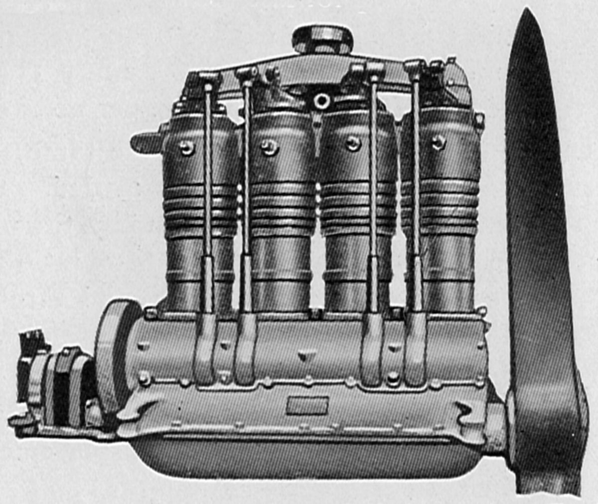
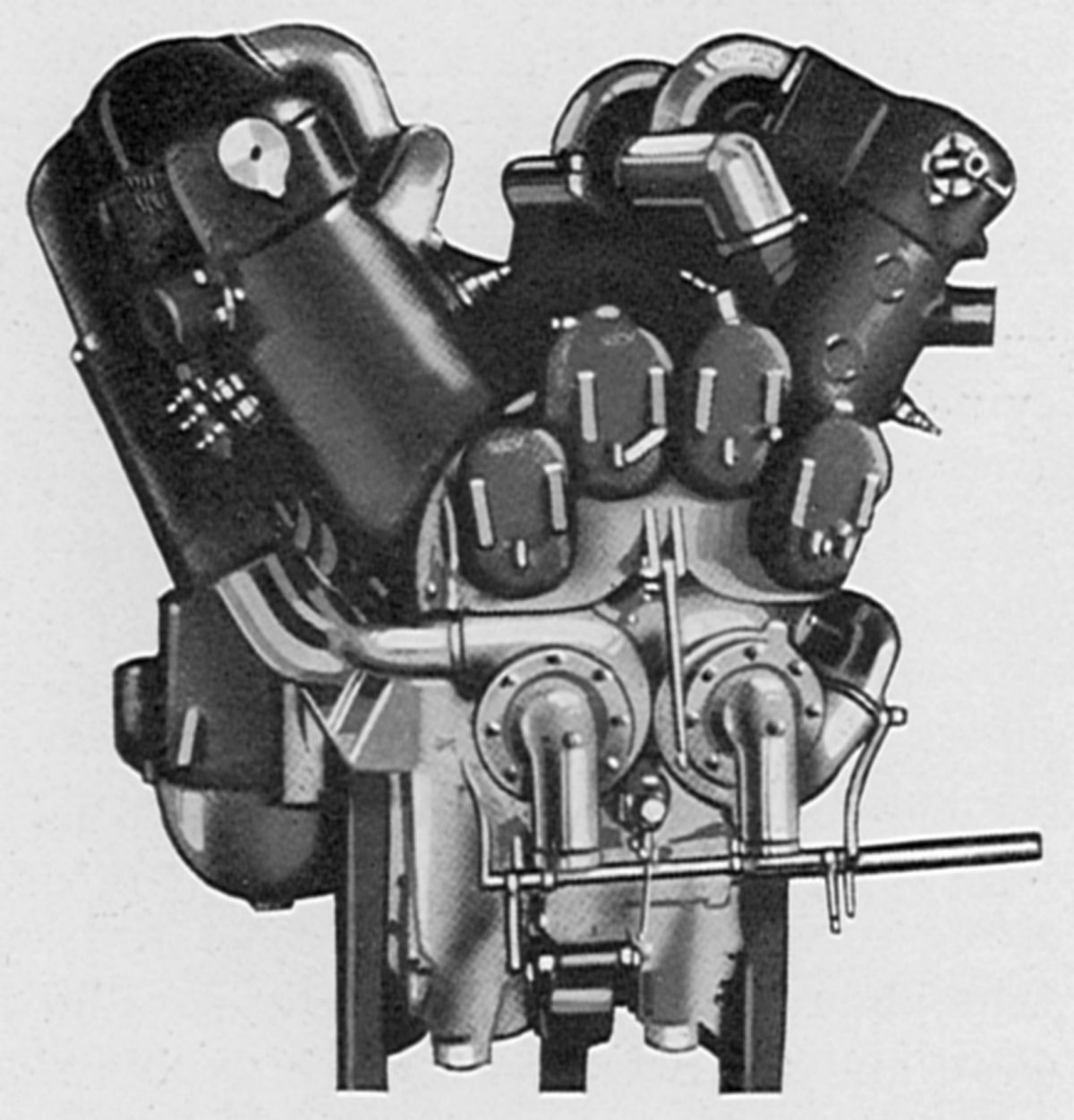
In 1912, Panhard built a water-cooled 90°V-8 with a 110 mm (4.331") bore, 140 mm (5.512") stroke and 10.644 l (649.52 in³) displacement that was rated 100 hp at 1,500 rpm and weighed 199.58 kg (440 lb). The iron cylinders were cast with integral water jackets in blocks of four. The side-by-side L-head valves were actuated via tappets from a camshaft in Vee. The pistons were of pressed steel and the connecting rods had H-section shanks. The camshaft was driven from both ends and the propeller was mounted on a camshaft extension.
 |
 |
 |
| Panhard V-12-J (AEE) | ||
The V-12-J, introduced in 1915, was a water-cooled 60° V-12 with a 115 mm (4.528") bore, 170 mm (6.693") stroke and 21.189 l (1,293.05 in³) displacement. The direct-drive version was rated 340 hp at 1,700 rpm, weighed 450 kg (992 lb) and had a 0.452 lb/hp/hr specific fuel consumption. The geared version was rated 350 hp at 1,800 rpm and weighed 489.9 kg (1,080 lb). The separate cast iron cylinders were mounted on the aluminum alloy crankcase offset 20 mm (0.787") from the crankshaft center. Valves with 56 mm (2.205") clear diameters were inclined in the cylinder head. A seven-bearing camshaft, enclosed in a long aluminum housing atop each cylinder bank, operated the valves through rocker arms. Inlet valves opened 5° early and closed 35° late; exhaust valves opened 50° early and closed 15° late. The cast aluminum pistons had six internal ribs and four top rings. The fork-and-blade connecting rods had H-section shanks. A six-throw seven-main-bearing crankshaft had thin disks as crank cheeks between each crankpin and large diameter main journals. Panhard carburetors were situated in the Vee, and two centrifugal pumps, mounted at right angles to the crankshaft and driven by spiral gears, circulated water. When equipped with air starters a distributing disc was mounted on a camshaft housing at the propeller end. The pressure lubrication system carried its oil supply in a large crankcase reservoir separated by large screens.
 |
| Panhard V-12 (AEE) |
An experimental direct-drive 60° V-12 with a 115 mm (4.528") bore, 170 mm (6.693") stroke, 21.189 l (1,293.04 in³) displacement and 5.3:1 compression ratio was rated 500 hp at 1,500 rpm and weighed 427.3 kg (920 lb).
Another Panhard 60° V-12, similar to the V-12-J design, had a 165 mm (6.496") bore, 180 mm (7.087") stroke, and 48.186 l (2,818.45 in³) displacement was rated at 500 hp.
 |
| Panhard W16 (AEE) |
The W16, a direct-drive water-cooled double-V-16 was exhibited at the Paris Aero Show in January 1920. It was the largest aircraft engine Panhard built. With a 145 mm (5.709") bore, 170 mm (6.693") stroke, 44.915 l (2740.9 in³) displacement and 5.0:1 compression ratio, it was rated 650 hp at 1,600 rpm and 700 hp at 1,700 rpm. Fuel consumption was 0.54 lb/hp/hr.
The cylinders were arranged in four rows of four cylinders each, all being located above the horizontal centerline and with 45° separating each adjacent row for a 135° total included angle between the outer rows. The separate steel cylinders had welded-on sheet-steel jackets. Four vertical valves in each head were operated by two push rods from one of the two camshafts in the crankcase outer Vees. A roller at one end of the rocker arm contacted a bridge between each valve pair. A four-throw five-main-bearing single-plane crankshaft was fitted. The articulated connecting rods attached aluminum pistons with five rings each. Mixture was furnished by four Panhard and Levassor carburetors, and three gear pumps maintained pressure lubrication. Two magnetos with double distributors were mounted crosswise at each engine end and fired four spark plugs per cylinder. The engine was 1,295 mm (51") long, 1,245 mm (49") wide and 1,092 mm (43") high.
The V-12-M, a water-cooled 60° V-12, appeared 1922. It had a 165 mm (6.496") bore, 170 mm (6.693") stroke, 43,620 l (2,661.87 in³) displacement and 6:1 compression ratio. With its high compression ratio, it was designed to be throttled at sea level and develop its full 500 hp at 1,500 rpm rated power at 3,048 m (10,000 ft). It weighed 587.4 kg (1,295 lb).
 |
| Panhard VK-122 (A39) |
The VK-122 was a water-cooled 60° V-12 using the Knight double sleeve valve scheme and successfully competing against poppet-valve engines, taking second prize in French Government engine competitions in 1925. With a 140 mm (5.512") bore, 170 mm (6.693") stroke, 31.403 l (1,916.35 in³) displacement and 5.4:1 compression ratio, its output was 450 hp at 1,500 rpm and 550 hp at 1,800 rpm. It weighed 545.2 kg (1,202 lb), was 2,035 mm (80.1") long, 889 mm (35") wide and 899 mm (35.4") high. Panhard claimed the VK-122 had less height due to no overhead valve gear.
The forged steel cylinders were fitted with welded-on sheet-steel water jackets. Each cylinder had two reciprocating steel sleeves driven by eccentrics. The eccentrics were mounted on two shafts, one in each aluminum crankcase side. The use of steel instead of cast iron sleeves resulted in weight savings. Three narrow compression rings replaced the single deep ring originally used on Knight engines. A special Panhard-Levassor developed feature was white-metalling of the outer sleeve inner face and the steel cylinder walls. Both crankshaft and eccentric shafts were carried in seven plain bearings. The fork-and-blade connecting rods had tubular shanks. Steel caps and white-metal-lined bearings were used, and the piston pins were fixed in the upper connecting rod ends.
A single centrifugal pump having one inlet and two outlets circulated cooling water. Water flowed from the pump to the rear cylinder upper edge just above the exhaust port. Part of the water passed straight to the front cylinder outlet , part took a circular path around the cylinder head, and another part passed around the cylinder barrels. This system reduced the number of connections by half.
A dry-sump pressure-fed lubrication system was employed. A scavenging pump for each engine end and a central pressure pump delivered oil into the hollow crankshaft. A separate oil pump supplied the connecting-rod bearings. Oil from this auxiliary pump was delivered through a gallery to each bearing in succession where some was diverted into eccentric collector rings on the crankshaft webs, from which it flowed to the connecting rod bearings by centrifugal force.
The inlet manifolds were straight pipes with flanges attaching it to each cylinder row's outside. Arranged in groups of three cylinders, a Panhard-Levassor carburetor at each manifold's inner end simplified control routing. Fuel was fed by two A.M. pumps mounted at the engine rear beside the water pump. Two S.E.V. 12-cylinder magnetos furnished dual ignition. Compressed air was employed for starting via a disk distributor placed at the right eccentric shaft rear end and a valve in the head of each cylinder in that row.
 |
| Clerget-Panhard Diesel (A39) |
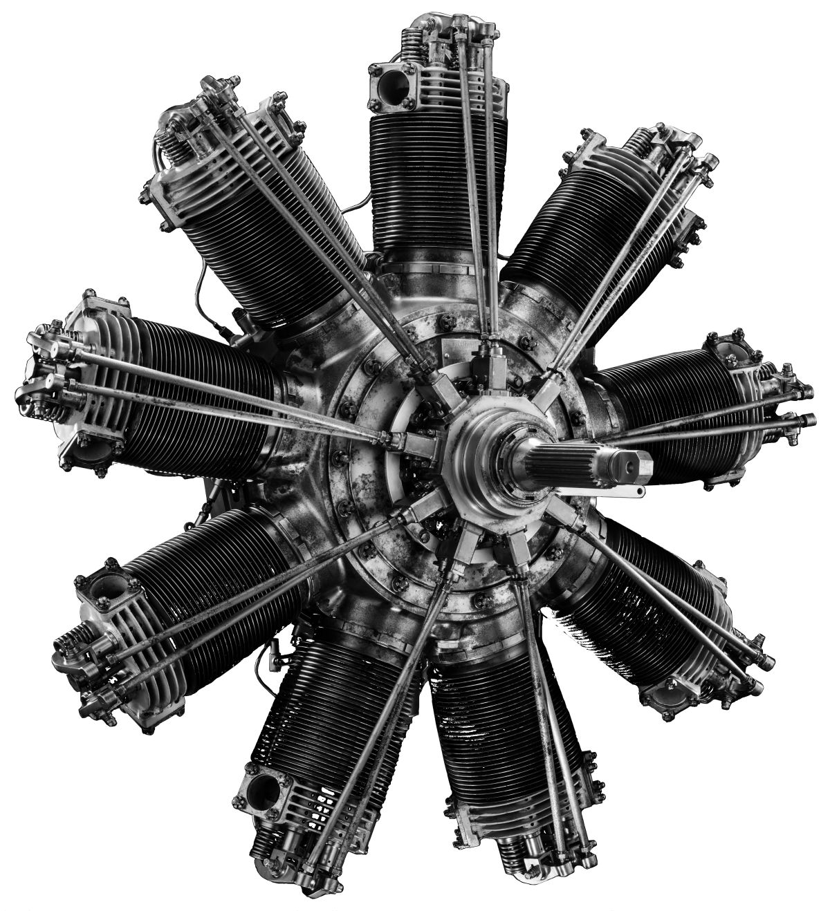
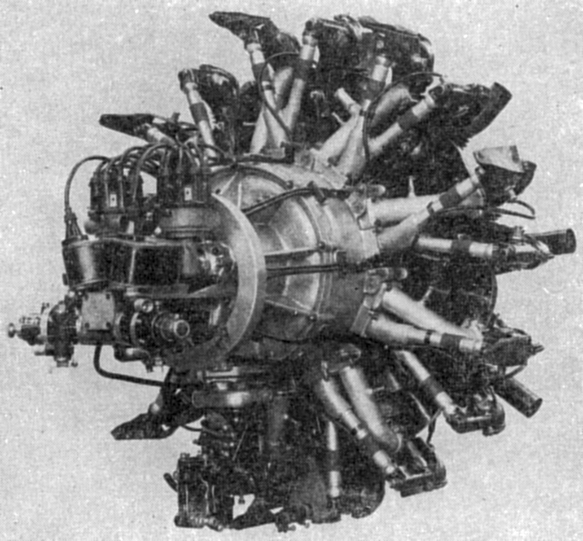
In 1928, Panhard and Levassor constructed air-cooled radial compression-ignition radials designed by Pierre Clerget. This smaller 9-cylinder engine had a 120 mm (4.724") bore, 130 33 (5.118") stroke, 13.232 l (807.49 in³) displacement, was rated 100 hp at 1,800 rpm and weighed 209.6 kg (462 lb). A larger air-cooled 9-cylinder radial had a 130 mm (5.118") bore, 170 mm (6.693") stroke, 20.308 l (1,239.27 in³) displacement and was rated at 200 hp.
The crankcase was made from pressed steel, not welded. The steel cylinder barrels, with integrally turned cooling fins and square threads, were screwed into the crankcase and then locked in place by large nuts. The aluminum cylinder heads, held to the barrel by four studs, contained an exhaust and an air inlet valve. An injector was placed between the valves. Two cylinder head studs supported the rocker arms that operated the valves via push rods and a front-mounted cam ring. The aluminum alloy pistons were fitted with five rings, the lower one acting as an oil scraper. These pistons had hemispherical cupped-shaped heads which, with the centrally located injectors, produced the necessary turbulence to secure good combustion. The articulated connecting rod system featured a one-piece, H-section master rod and interchangeable tubular-shank link rods. The crankshaft was made in two parts, the telescoping tapered and keyed crankpin joint made tight by a differential screw, which also separated the crankshaft parts when the engine was disassembled.
The dry sump lubrication system used one gear-type pressure pump to supply oil to engine bearings and one gear-type scavenge pump to remove used oil to a supply tank. The engines featured a decompression and oil drain valve. The exhaust valves were located at the cylinders' lowest point. Before the engine was started, all exhaust valves were simultaneously unseated by a manually-controlled mechanism, thereby draining any accumulated oil and providing compression release during starting. This same mechanism was also employed when the engine was stopped.
Fuel injection comprised a separate crankcase-mounted fuel pump for each cylinder, all driven at the crankshaft aft end. A soft copper tube capable of withstanding 14,000 psi carried fuel from each pump to that cylinder's injector. Another copper tube returned injector seepage back to the pump supply chamber. The pumps were operated by a single cam mounted on a helical crankshaft spline. By shifting the cam axially, the injection duration could be varied. The cam was in contact with four tappets located in a housing that rotated opposite the crankshaft direction at one-eighth speed. These pump plungers had circular segment-shaped feet that interfaced with the tappets. The tappets normally were returned by springs, but if a spring broke, the tappet would be returned by a stationary internal cam ring. The use of a single cam insured uniform fuel distribution, rapid injection with only a gradual cam contour change, and fuel injection rate independent of injection timing.
The injection pumps were completely immersed in a fuel chamber whose fuel supply was continuously circulated by small gear pump. Fuel passed through a filter and returned to the tank through a sight glass. The injector pump piston had a fixed stroke. Fuel entered through a port in the pump cylinder wall and was forced out through a check valve on the cylinder axis. A control lever moved the pump cylinder axially, changing the inlet port position relative to the plunger stroke and thus the effective pump volume. The pump control levers were connected by links to a control ring mounted on a cylindrical crankcase surface. The links and levers were adjustable so that fuel volume could be varied at both idle and full load. The injection valve housings could be independently removed so that piston position could be checked without engine disassembly.
The cylinder-head-mounted injectors' poppet valves were held their seats by coil springs. Grooves, which were almost tangential, were cut on the conical valve seat so that the high pressure fuel flow rotated the valve, cleaning the grooves of debris. These grooves were about 0.008" deep. The numerous shallow grooves assured high fuel velocity at all engine loads, and the nearly tangential injection direction produced a turbulence in proportion to the injection speed. The fuel used had a specific gravity of 0.86, although any heavy fuel oil could be used.
Peugeot
 |
 |
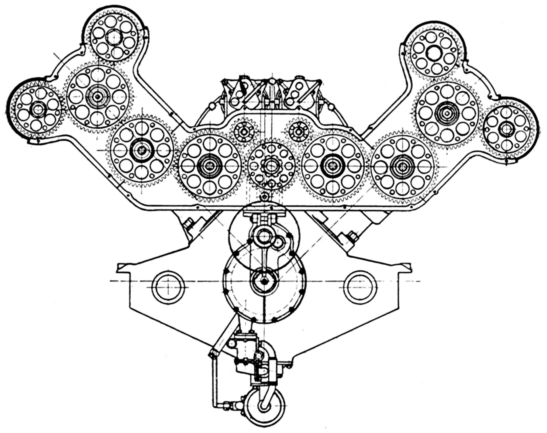 |
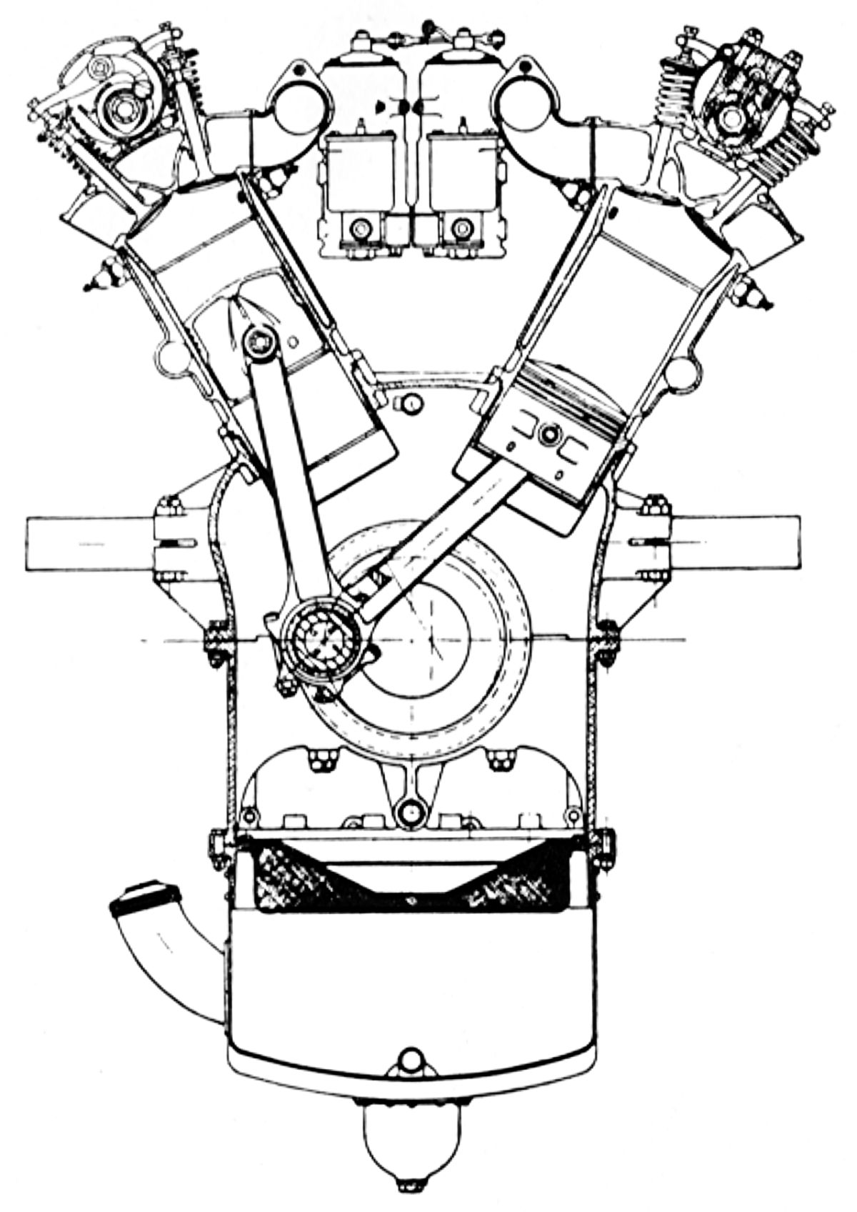
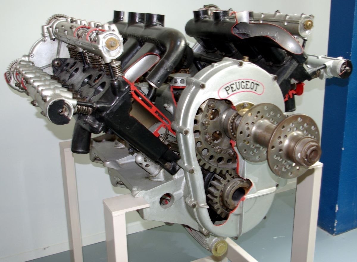
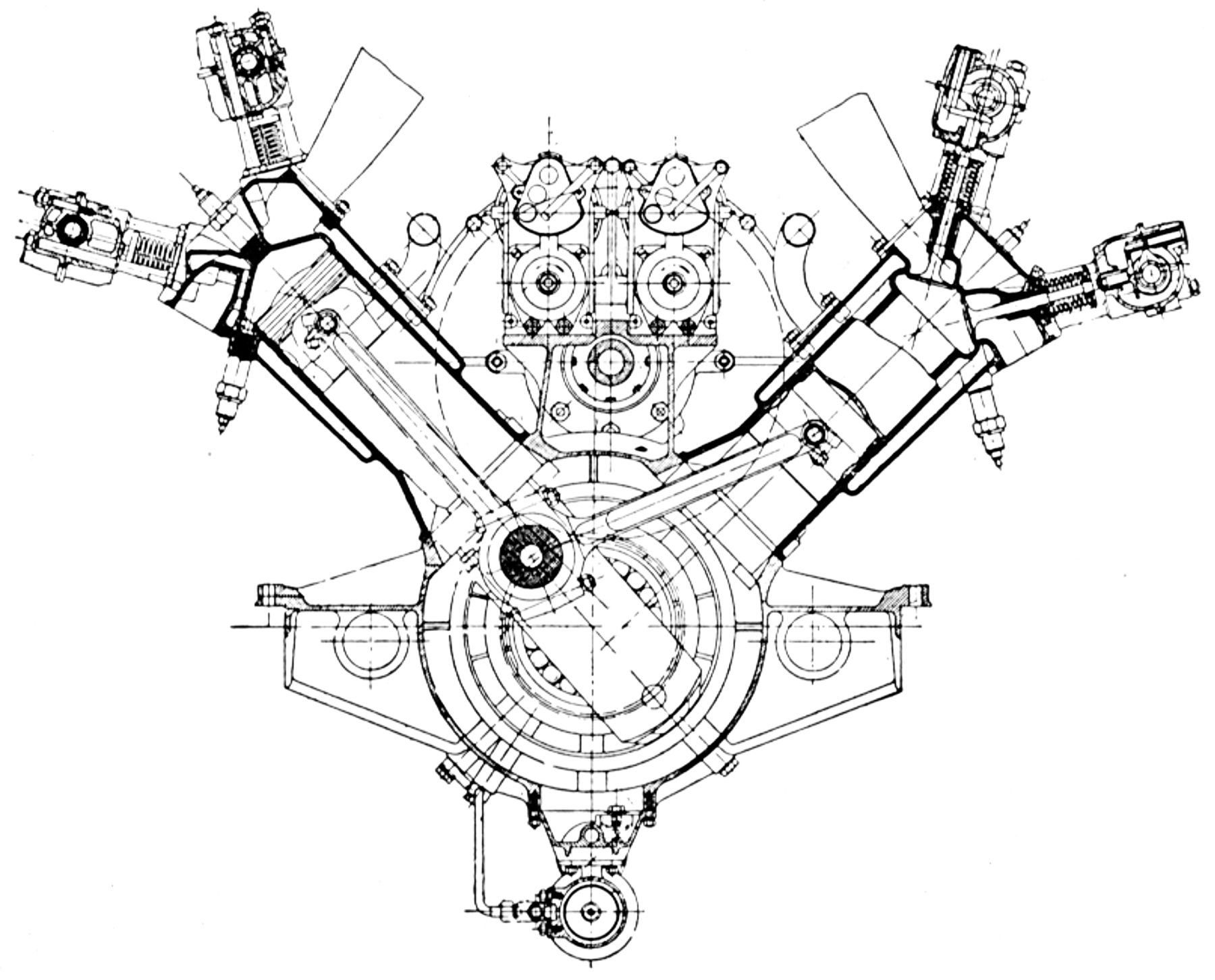
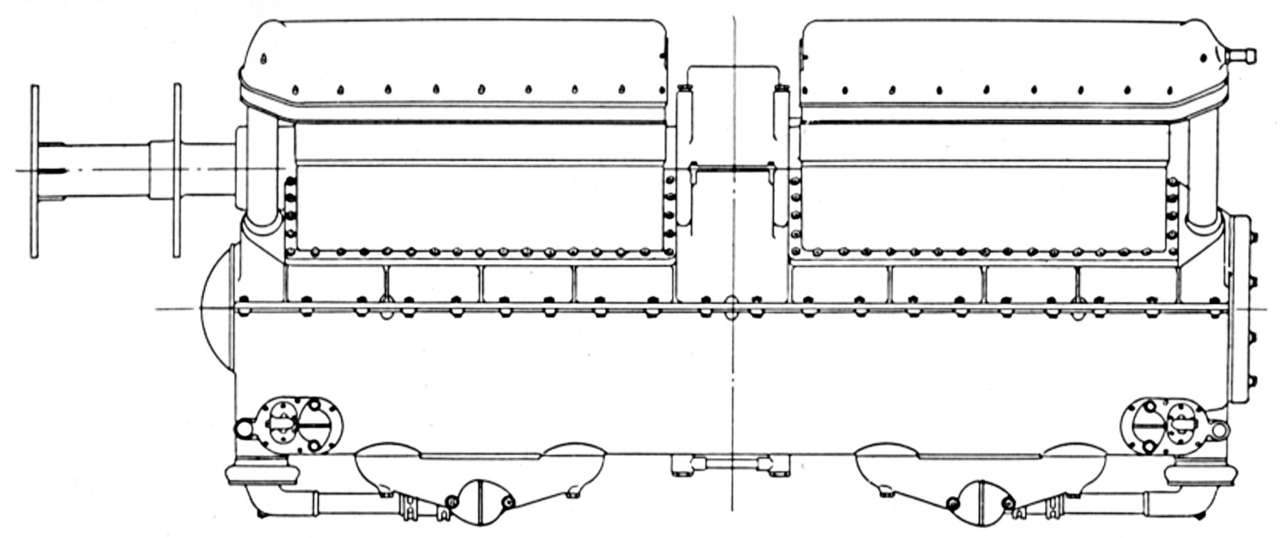
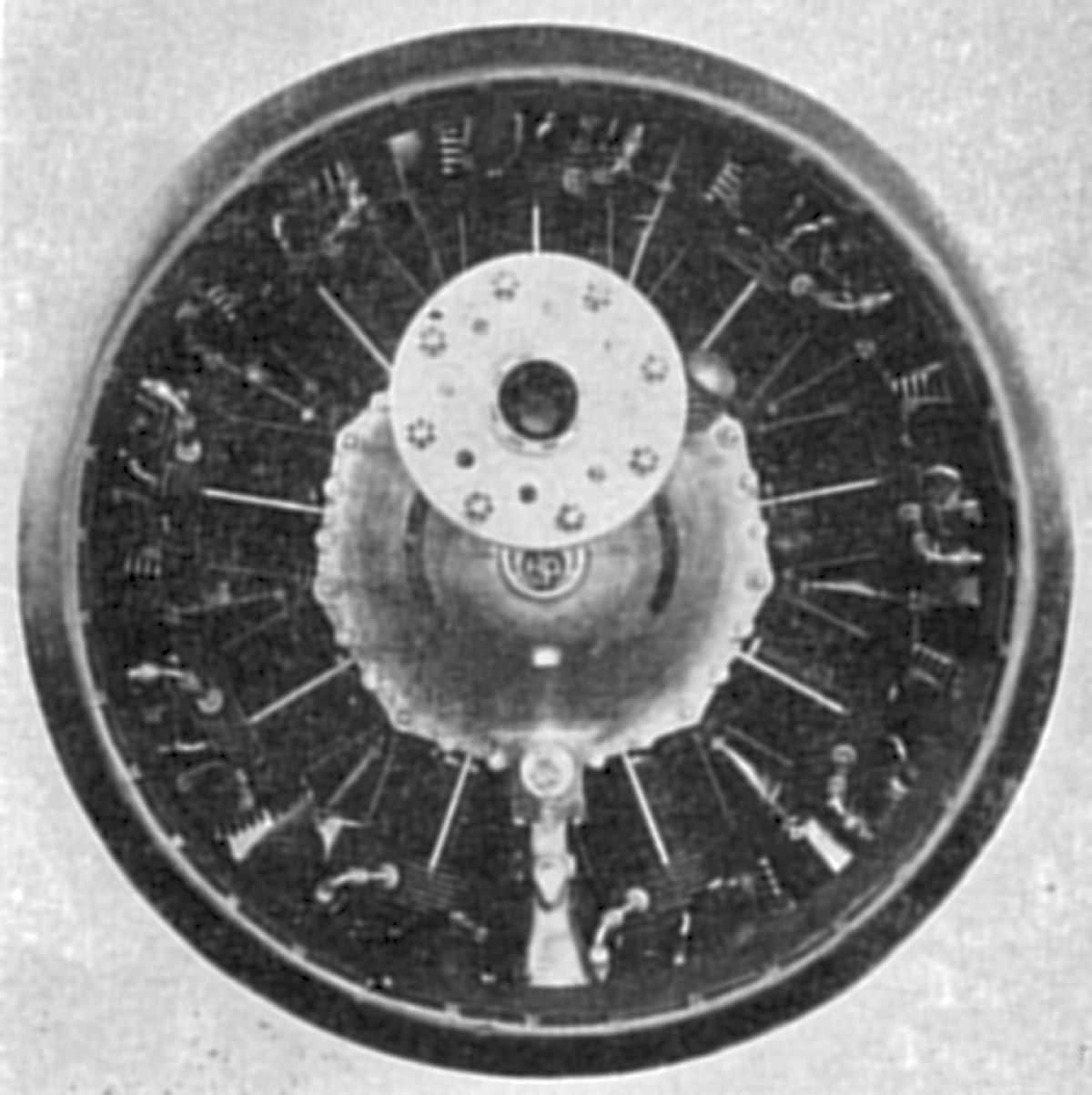
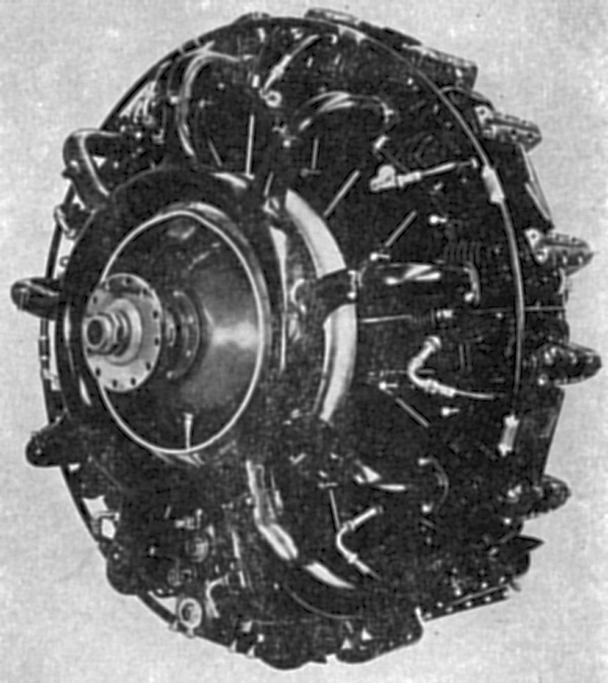
| L112 Cutaway (Wiki), Section, Gear Train (AEE) | ||
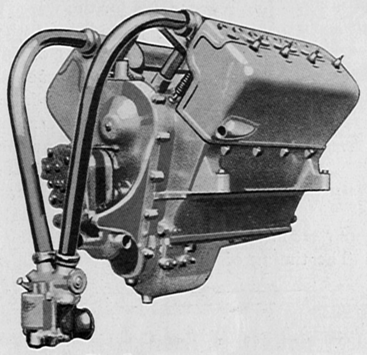
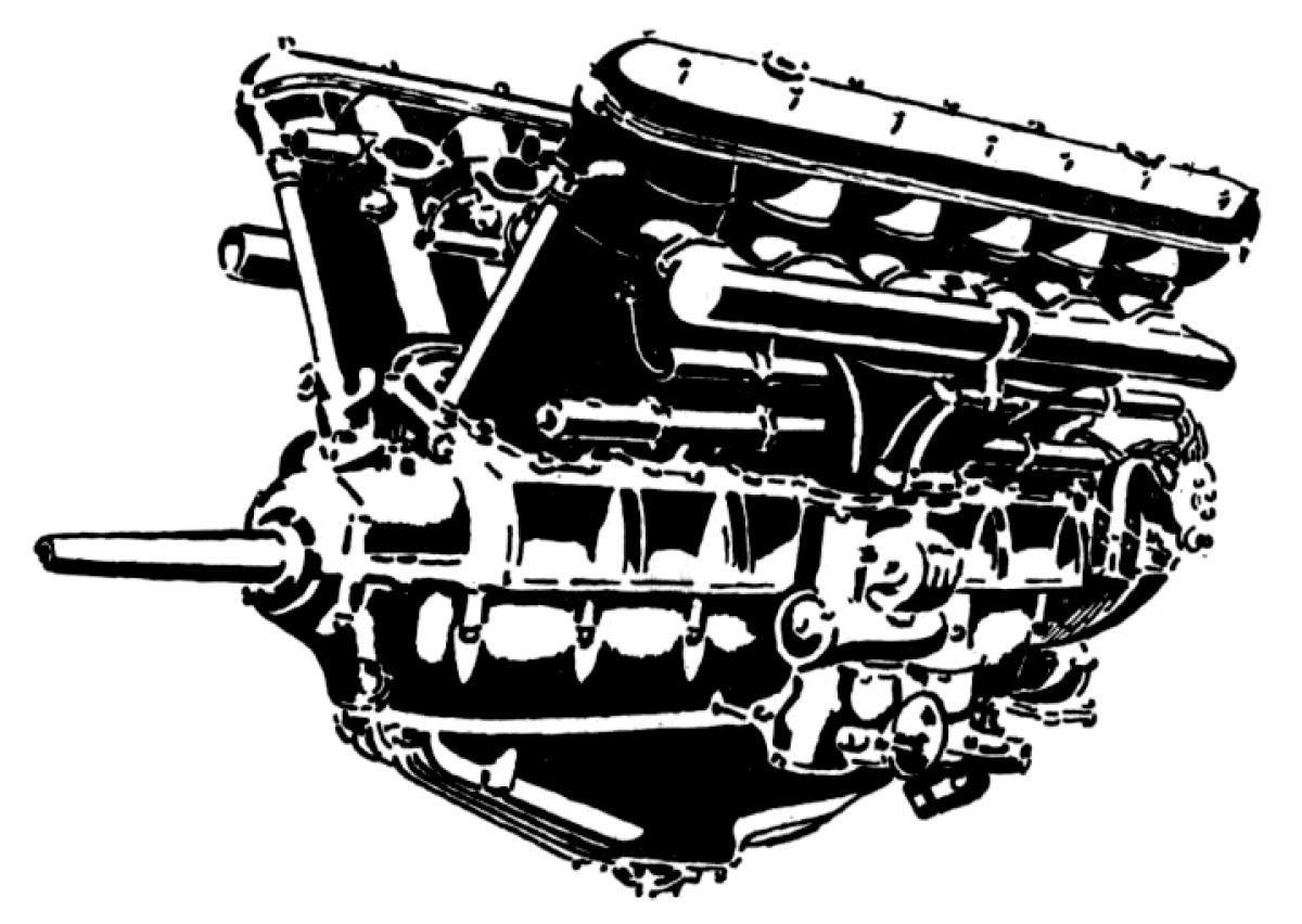
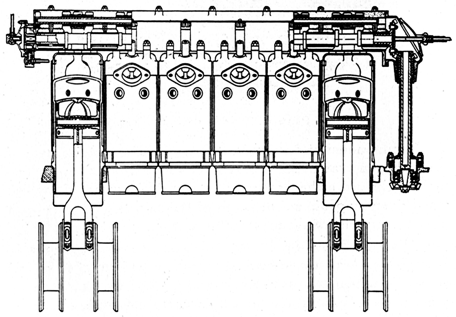
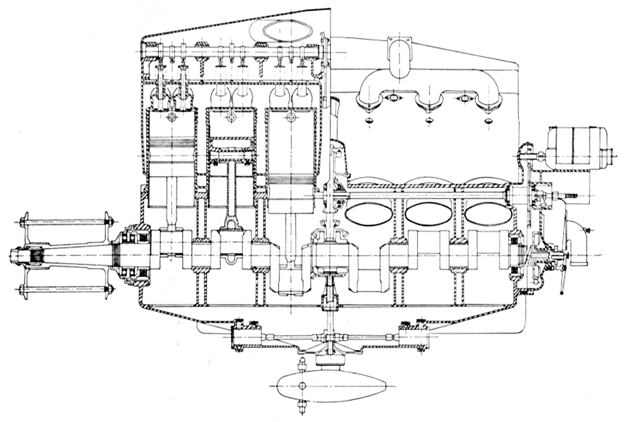
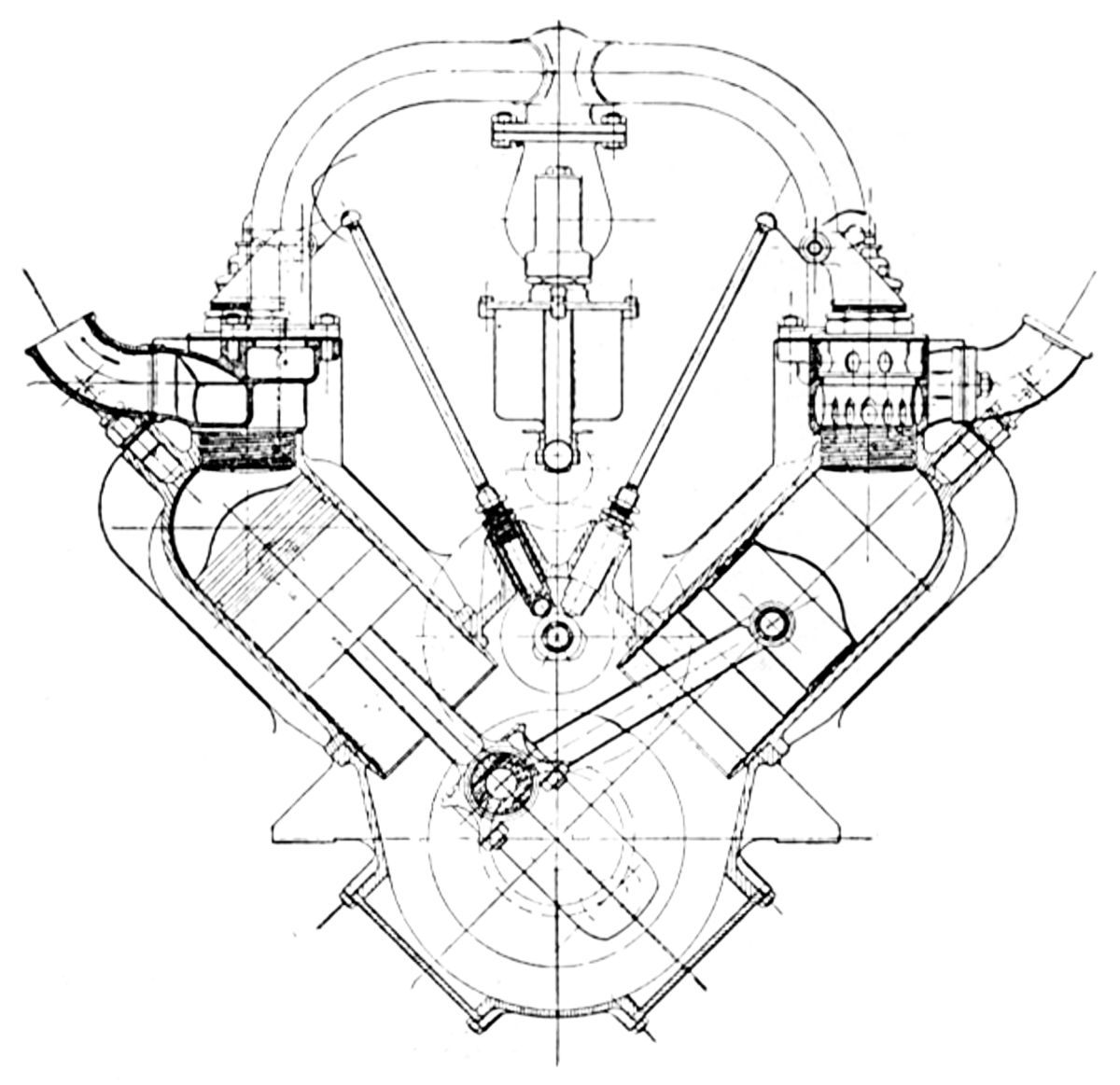
In 1905, Peugeot supplied a 14 hp V-twin to Alberto Santos-Dumont to power his dirigible No. 14. In 1910, the L112, a water-cooled 90° V-8 aircraft engine, evolved from Peugeot's automobile racing heritage. With a 100 mm (3.937") bore, 180 mm (7.087") stroke and 11.310 l (690.16 in³) displacement the L112 was rated 200 hp at 2,000 rpm and weighed 400 kg (882 lb). Spur reduction gears drove a propeller shaft mounted on ball bearings with a 2:1 reduction ratio. A shaft extending aft through the Vee drove the camshaft spur gear train and accessories. The barrel crankcase supported the four-throw crankshaft in three large double row ball bearings. The crankshaft was made in two sections, joined at the center bearing by a taper, key, and nut. The cylinders were cast from iron in blocks of four with integral water jackets. The large cored opening at the cylinder block ends were closed by aluminum plates secured by screws. The cylinder blocks were offset from the crankshaft centerline. Four inclined valves with 44 mm (1.732") clear diameters in each cylinder head ran in bronze guides. Four overhead camshafts, each enclosed in an aluminum housing, operated the valves through tappets. The inlet valves opened 11.75° late and closed 46.12° late; the exhaust valves opened 52.50° early and closed 7.75° late. The pistons were machined from steel forgings and fitted with two rings. The fork-and-blade connecting rods had H-section shanks. Each cylinder bank featured a Claudel carburetor attached to a jacketed inlet manifold that was heated by exhaust gases. Cooling water was circulated by two centrifugal pumps, and two eight-cylinder S.E.V. magnetos provided dual ignition. One spark plug was in the cylinder head center and the other was inverted just below the outboard inlet valves. A dry-sump pressure-fed lubrication system was provided.
 |
 |
 |
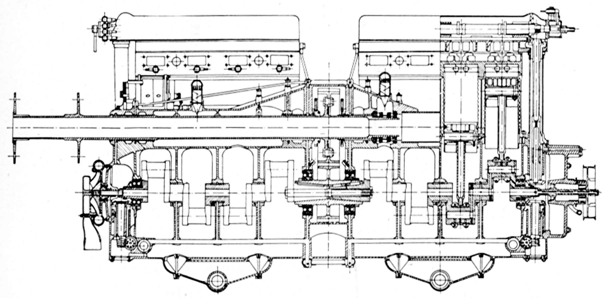 |
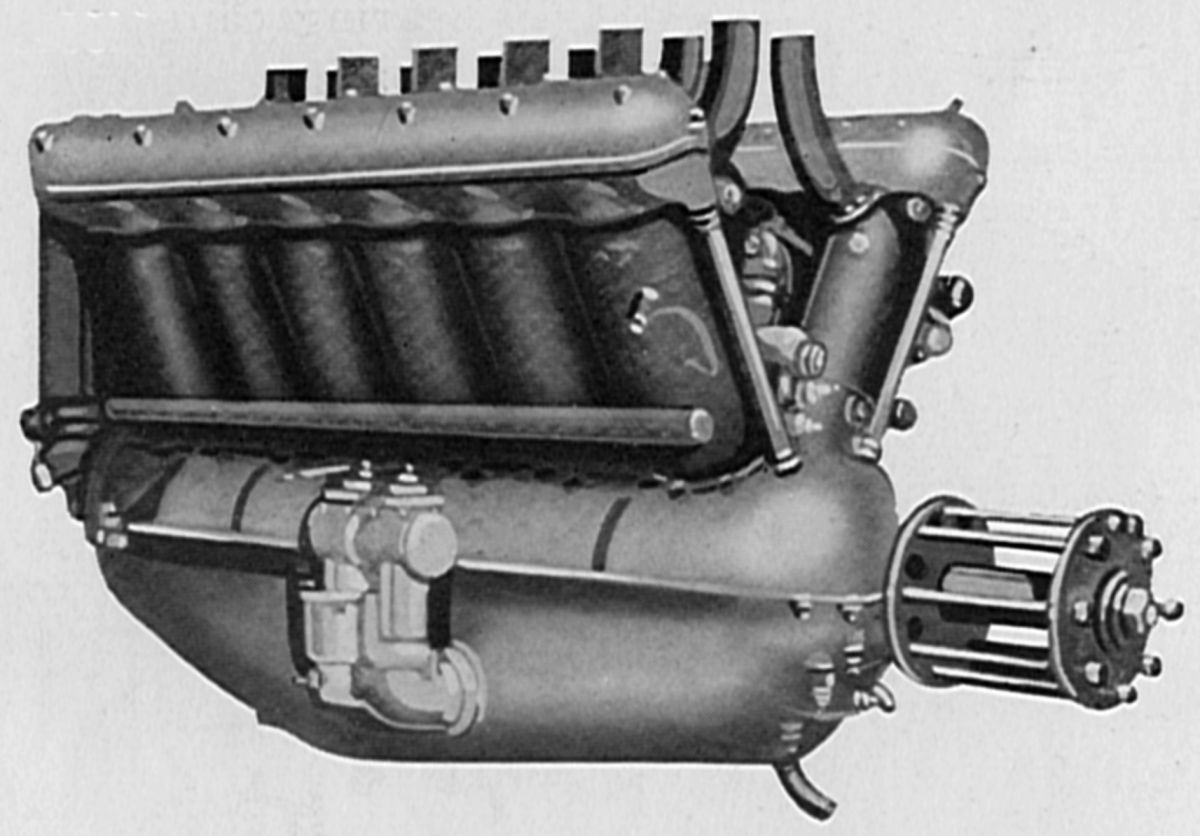
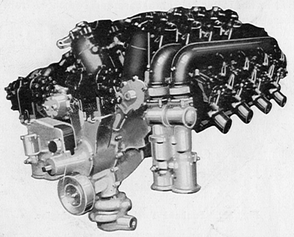
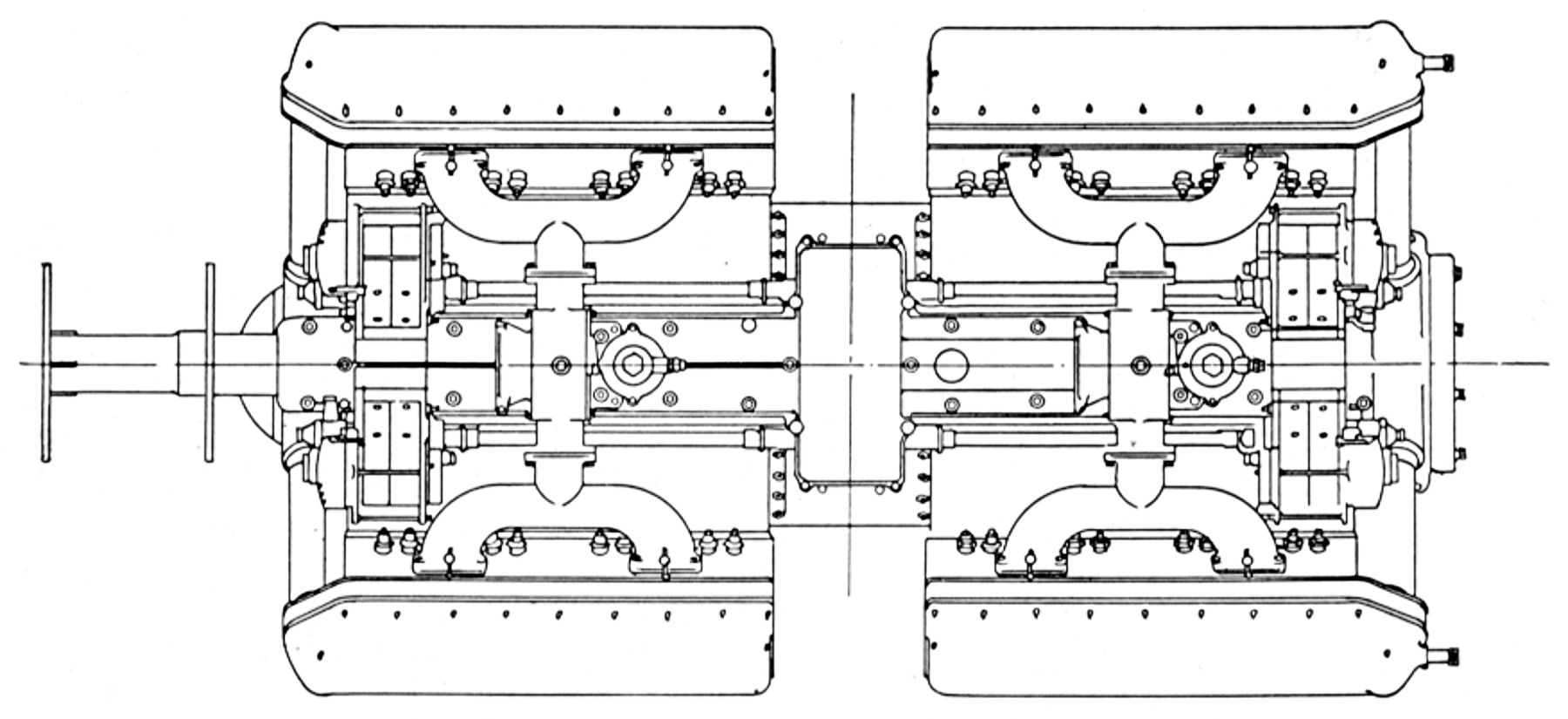
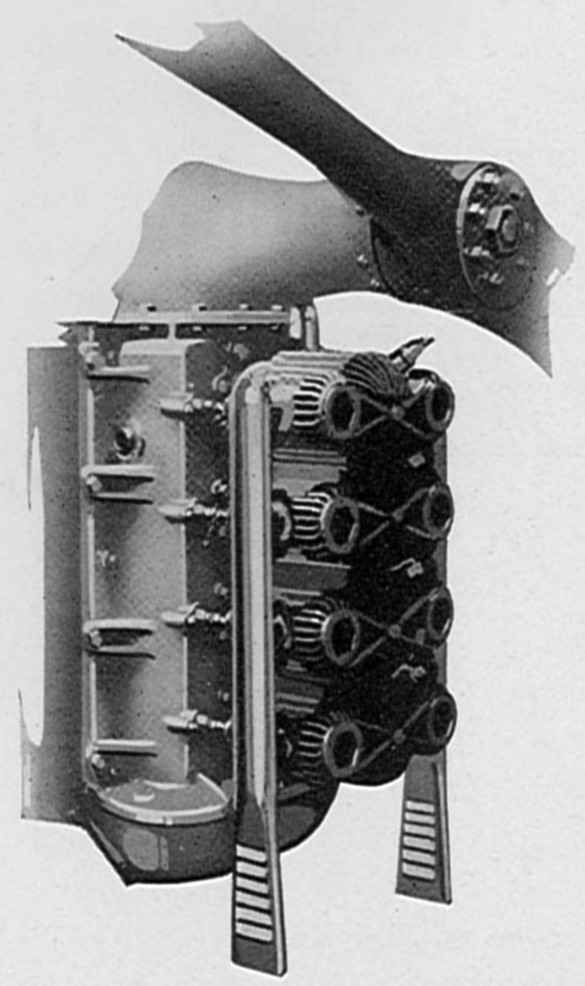
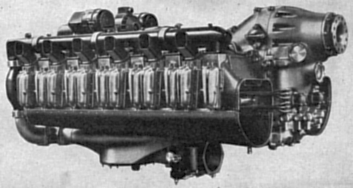
| 16AJ Left, Aft, Top, Longitudinal Section (AEE) | |||
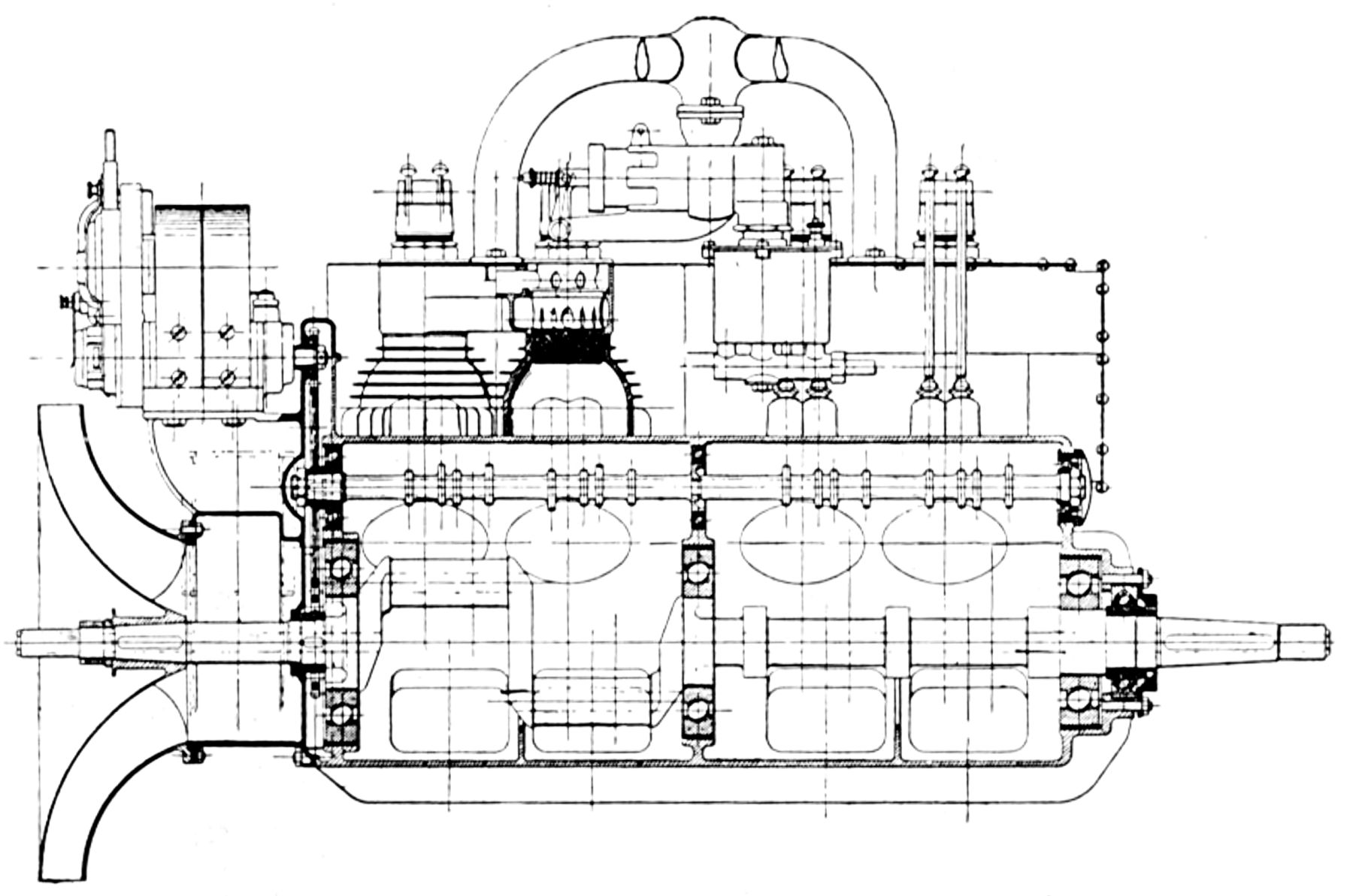
The 16AJ, based on the Henri Victor Jules Jouffret patent (US 1,318,209) appeared in 1919. This 90° V-16 drove its propeller shaft at a 1.333:1 ratio from the center of two V-8s placed end-to-end. With a 120 mm (4.724") bore, 160 mm (6.299") stroke, 28.953 l (1,766.82 in³) displacement and 5:1 compression, it delivered 440 hp at 1,800 rpm and weighed 476.8 kg (1,049 lb). It was 1,956 mm (77") long, 978 mm (38.5") wide and 800 mm (31.5") high. Steel cylinders were screwed into cast-iron cylinder heads and surrounded by aluminum water jackets. Each cylinder had four vertical valves with 37 mm (1.457") clear diameters and 45° seats. A single enclosed overhead camshaft on each bank operated the valves via double rocker arms. Each of the two four-throw flat-plane crankshafts were supported at the outer ends by double-row ball bearings and at the intermediate positions by three plain bearings. These shafts were joined to the driving gear at engine center by tapers and keys. Again, double-row ball bearings supported the crankshafts. The long propeller shaft ran on amply proportioned plain bearings. The aluminum pistons had five vertical internal ribs and were fitted with two sets of double compression rings and a single oil scraper ring. The fork-and-blade connecting rods had tubular shank sections. A large centrifugal water pump mounted at the crankcase fore end was driven from the crankshaft. Two duplex carburetors, situated in the Vee, led into water-jacketed four-cylinder manifolds. Four eight-cylinder magnetos supplied dual ignition. A double gear oil pumps at each engine end was driven by a worm gear and was adjusted to maintain a constant 10 psi pressure. A compressed air starter served each 8-cylinder group and the air distributor gears were fastened to the camshaft ends. A generator drive pulley was driven from the crankshaft aft end and arranged with a disengaging mechanism and hand clutch.
In 1922, Peugeot built another water-cooled V-16, which was an enlarged and improved 16AJ. With a 130 mm (5.118") bore, 180 mm (7.087") stroke and 38.227 l (2,332.75 in³) displacement it was rated 500 hp at 1,000 rpm. The propeller reduction gears were located at the engine center as before. However, the enclosed overhead camshafts were driven by gears from the engine center instead of the shaft and bevel gear drive at their ends. A carburetor was located at the cylinder block exterior and fed the inlet manifold through a cylinder block passage.
 |
 |
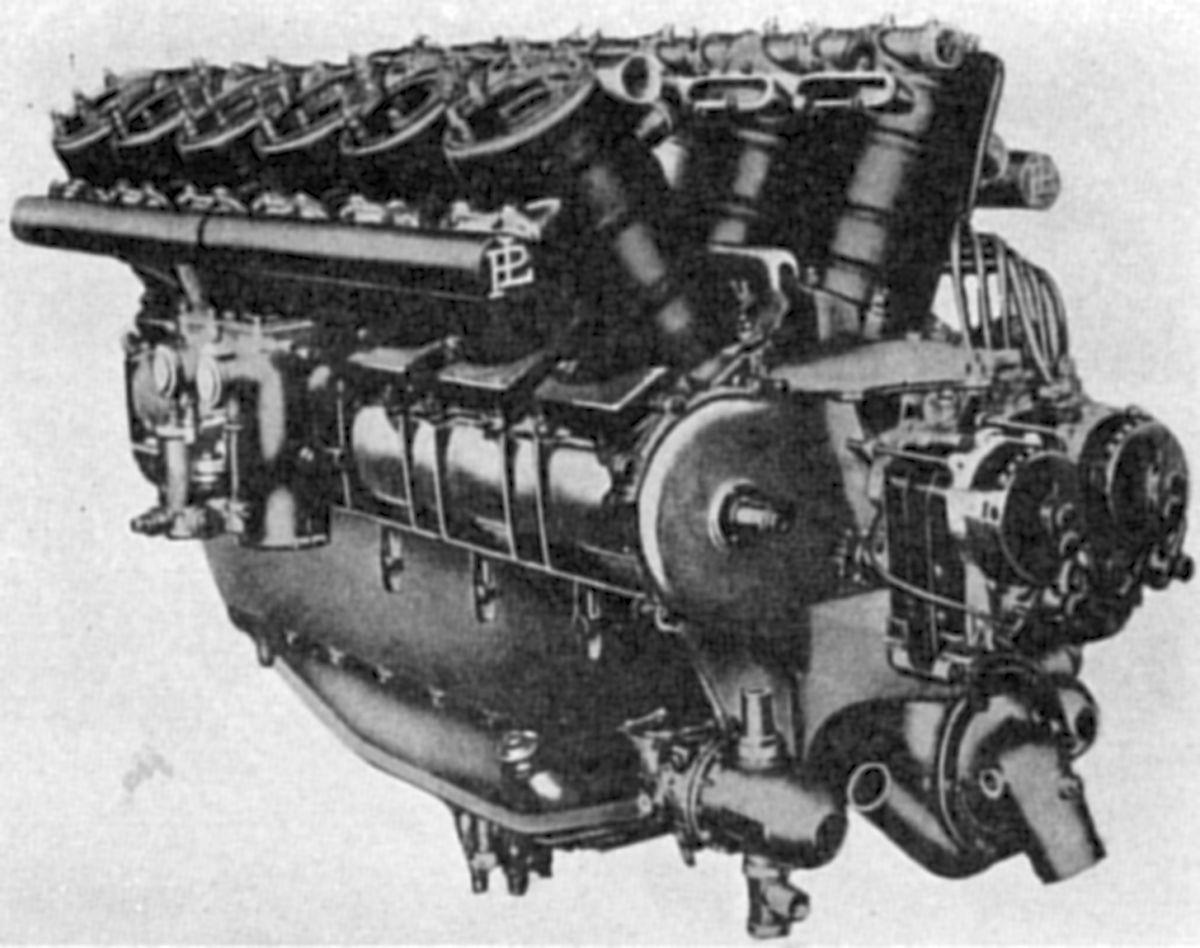
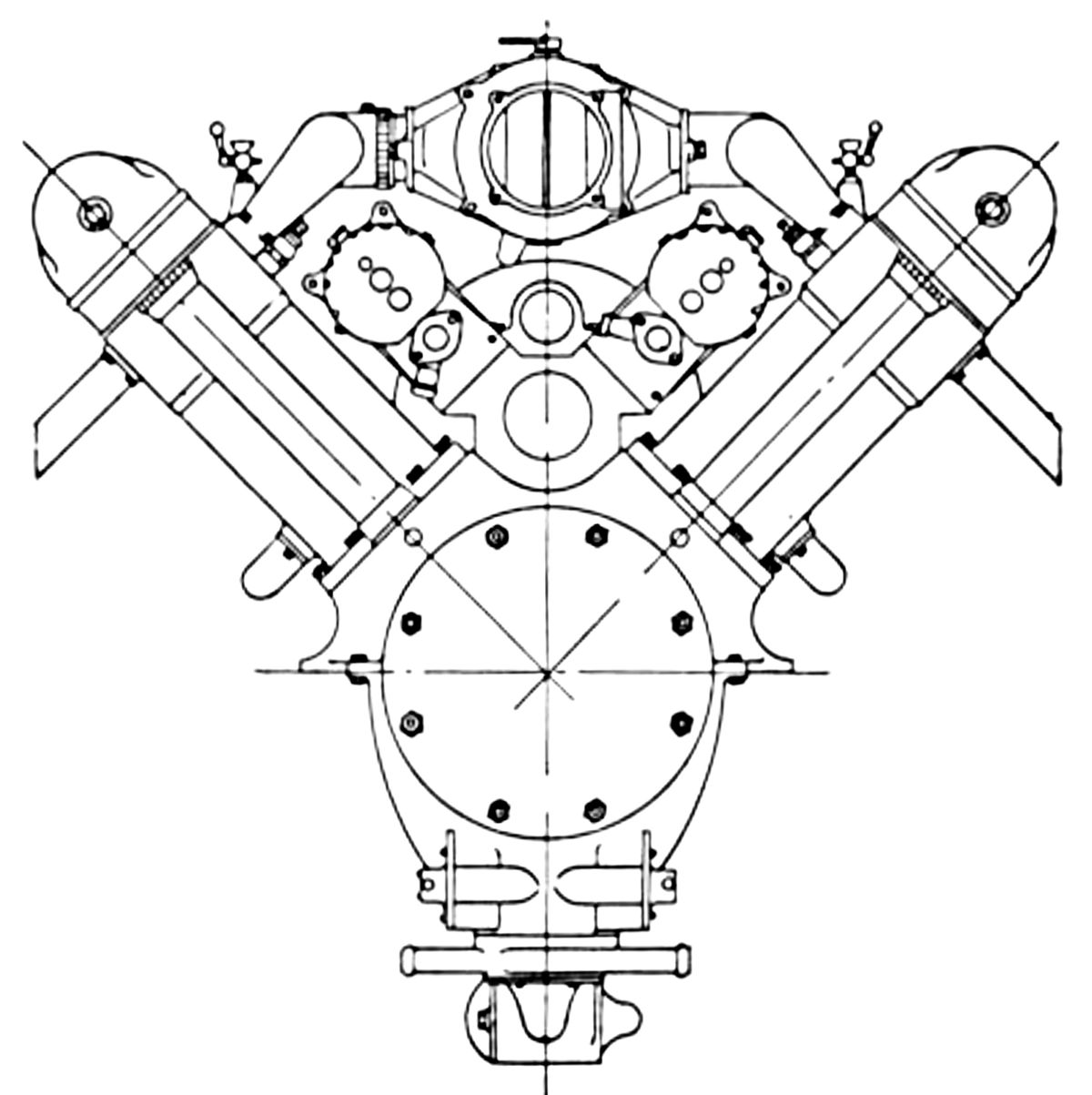
| L41 Aft, Longitudinal Section (AEE) | |
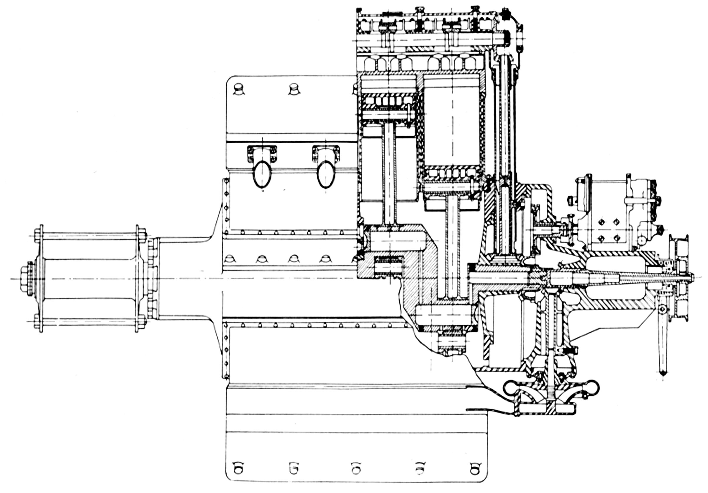
The Peugeot L41 was a direct-drive water-cooled 60° V-12 with a 160 mm (6.299") bore, 170 mm (6.693") stroke, 41.017 l (2,502.99 in³) displacement and 4.7:1compression ratio. It was rated 600 hp at 1,600 rpm and weighed 576.1 kg (1,270 lb). It was 2,032 mm (80") long, 1,067 mm (42") wide and 1,092 mm (43") high. The cylinders were enameled aluminum alloy cast in blocks of three, with closed-end steel liners screwed into place. Four vertical valves in each cylinder head with 52 mm (2.047") clear diameter and 45° seats were operated by rocker arms from an enclosed overhead camshaft in each bank, driven at their centers by vertical shafts and bevel gears. The six-throw seven-main-bearing crankshaft ran on plain hearings except at the ends where roller hearings were employed. The fork-and-blade connecting rods had tubular shank sections. The aluminum pistons had six parallel ribs underneath the head, and were fitted with three double-ring compression sets and one oil-scraper ring. Each cylinder bank was fed from a duplex carburetor outside the bank that received its intake air through a passage in the lower crankcase half. The inlet pipes crossed to inside the Vee through the camshaft covers. Cooling water was circulated by two centrifugal pumps at the engine rear. Just above the water pumps, in two separate planes, were four symmetrically-mounted S.E.V. six-cylinder magnetos that supplied dual ignition. Two double-gear oil pumps in the crankcase lower half, immediately below the center main bearing, were driven from a vertical shaft and bevel gears.
 |
 |
| 16X Aft, Longitudinal Section (AEE) | |
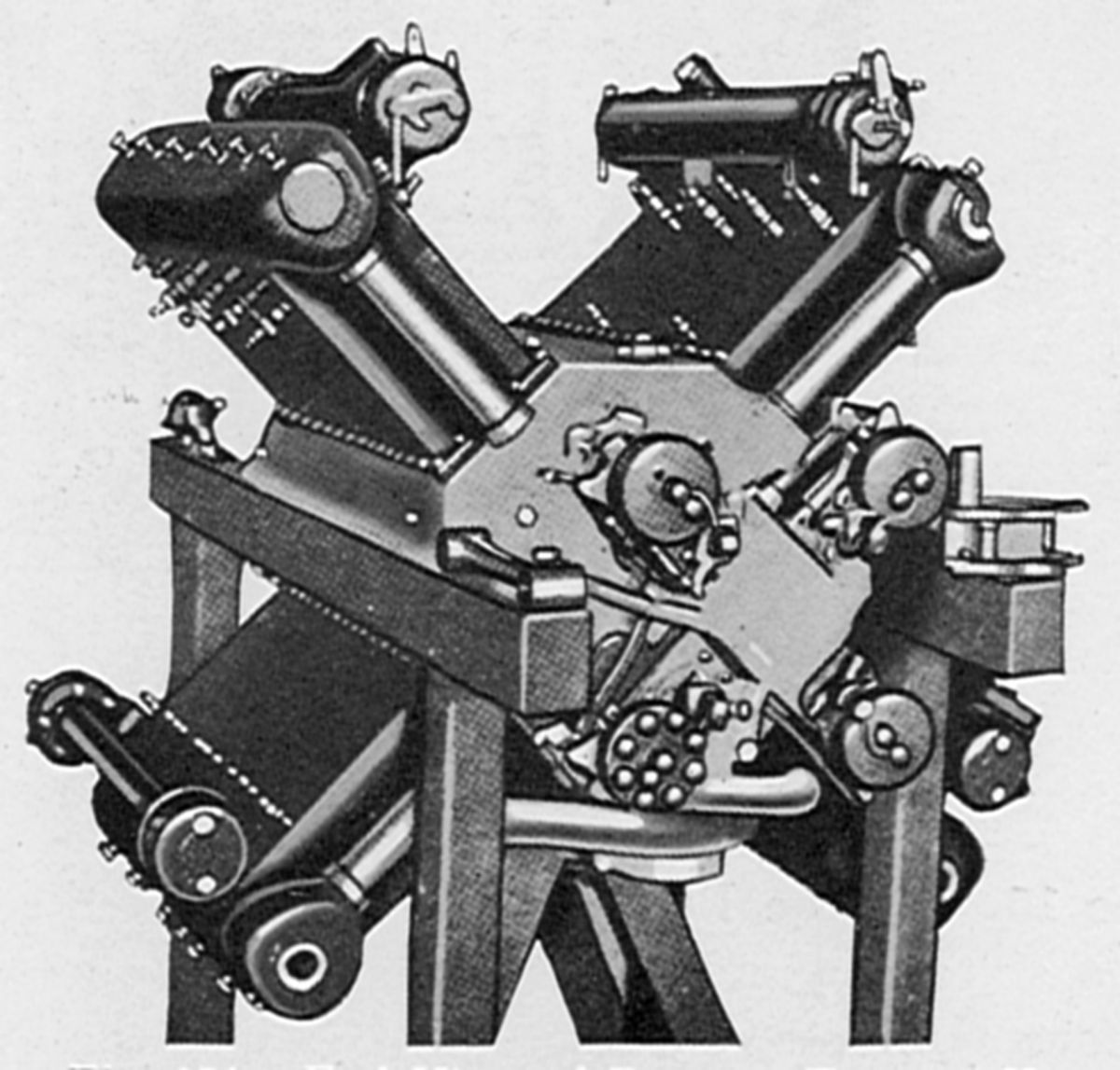
The 16X was a direct-drive water-cooled X-16 with four rows of four cylinders 90° apart. With a 130 mm (5.118") bore, 170 mm (6.693") stroke, 36.103 l (2,203.15 in³) displacement and 5.3:1 compression ratio, it developed 500 hp at 1,400 rpm and weighed 450.9 kg (994 lb). It was 1,600 mm (63") long, 953 mm (37.5") wide, and 953 mm (37.5") high. The cylinders, formed in blocks of four, consisted of steel barrels screwed and welded into a cast iron cylinder heads, and then encased in aluminum water jackets, which were bolted to the crankcase. Each cylinder had four vertical valves with a 40 mm (1.575") clear diameters and 45° seats operated by double rocker arms with an eccentric roller adjustment. The enclosed overhead camshafts were driven at the aft ends by shafts and bevel gears.
The two four-throw crankshaft sections were connected at the center hearing by a pinned cone blocked by a bolt. The crankshaft was supported by a large central ball bearing and two long plain end bearings. The articulated connecting rods had tubular shank sections. Aluminum pistons were fitted with two double and one single compression rings, plus a single lower oil scraper. One centrifugal pump, mounted under the engine rear, circulated cooling water to all four cylinder blocks. Forced lubrication was maintained by gear pumps, and dual ignition was provided by four magnetos at the engine rear in the cylinder planes. Each cylinder bank had a special carburetor attached to inlet manifold end and warmed by water circulation. A compressed-air starter was provided for the two upper cylinder banks.
The 12L was a water-cooled 60° V-12 similar to the L41. With a 160 mm (6.299") bore, 175 mm (6.890") stroke and 42.233 l (2,577.22 in³) displacement, it was rated 550 hp at 1,500 rpm and developed 600 hp at 1,600 rpm. Weight was 648.6 kg (1,430 lb). Fuel and oil consumptions were 0.506 and 0.044 lb/hp/hr. The six-throw seven-main-bearing crankshaft had plain bearings in the middle and roller bearings at the ends. The pistons were aluminum castings, and the connecting rods were fork-and-blade. The two inlet and two exhaust valves per cylinder were controlled by enclosed overhead camshafts. The cylinders were aluminum block castings fitted with steel liners. The pressure-fed dry-sump lubrication system used double pumps. Two centrifugal pumps circulated the cooling water, and a single duplex carburetor supplied the mixture. Four S.E.V. magnetos furnished dual ignition. A Dumannois device (US 1,396,322) in conjunction with an auxiliary magneto was used for starting. The 12L was the last aircraft engine constructed by Peugeot.
 |
 |
| Pipe Sections (AEE) | |
Pipe
The Pipe air-cooled V-8, designed and built in Belgium during 1910, was similar to the French Renault air-cooled engines. With 100 mm (3.397") bore and stroke, and 6.283 l (383.42 in³) displacement, it was rated 50 hp at 1,200 rpm, 70 hp at 1,950 rpm and weighed 131.1 kg (289 lb). Cast-iron cylinders, with integrally cast cooling fins, had concentric valves in the cylinder head. Opposite cylinder banks were staggered to permit the side-by-side connecting rods. The crankshaft ran on three large ball bearings, as did the single camshaft in the Vee. Forced air circulation was maintained through the aluminum baffling by two blowers. A later V-8 was reported to produce 110 hp.
 |
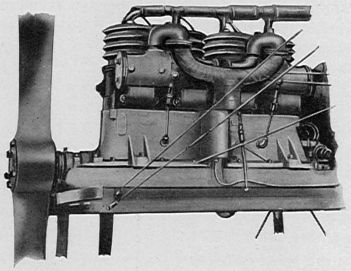
| A-4 (AEE) |
Potez
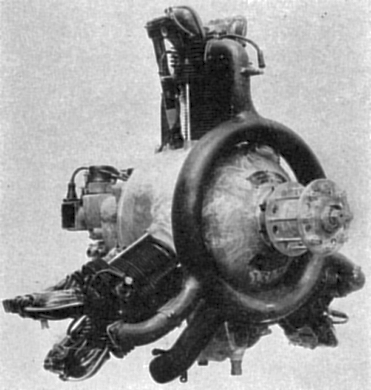
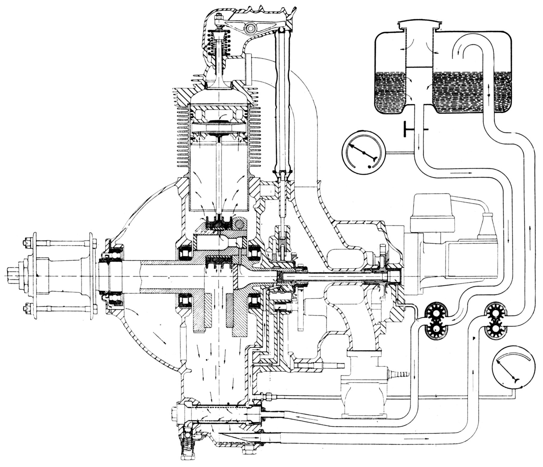
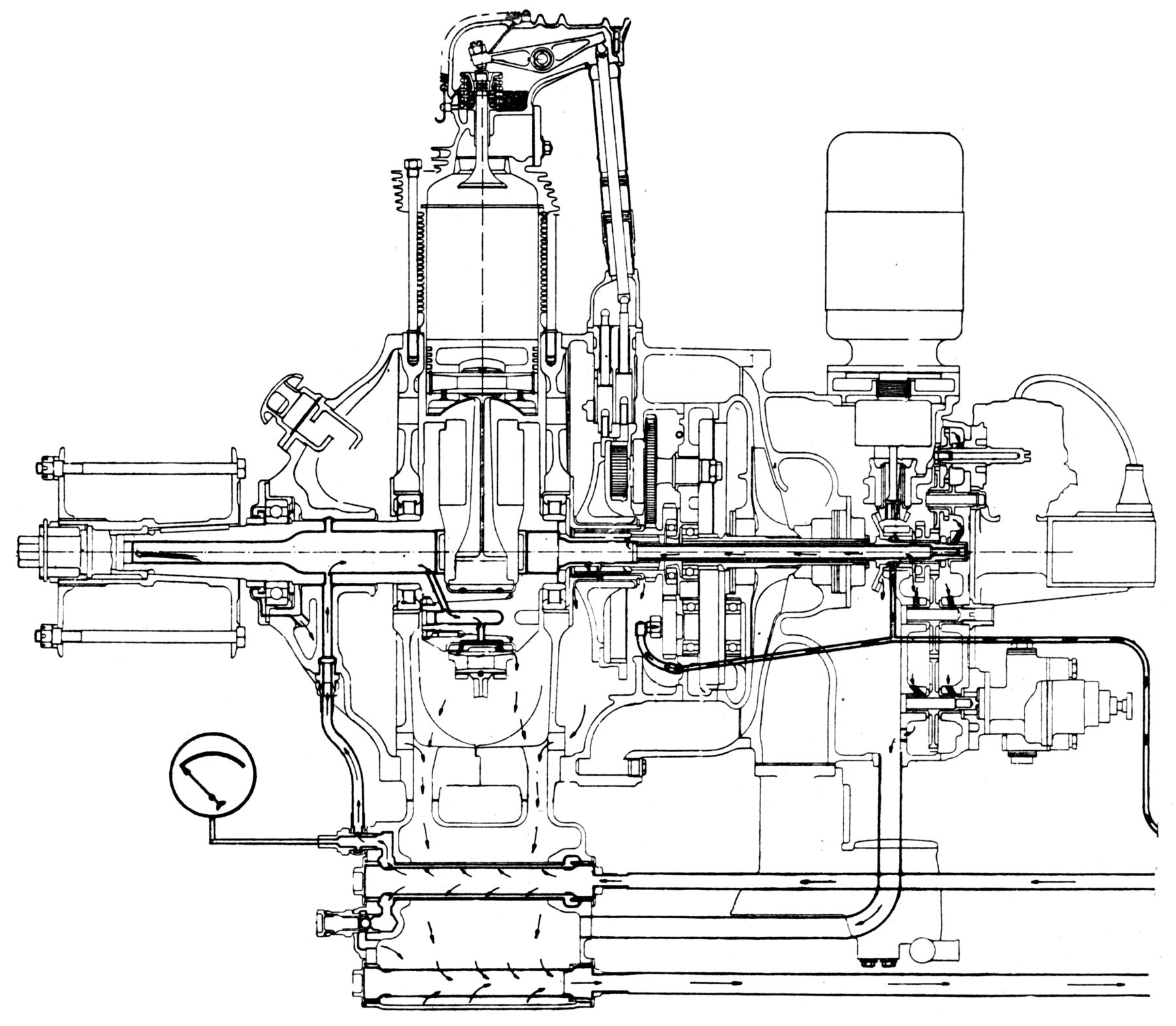
The Societé des Aeroplanes Henry Potez of Paris, France had an engine plant at Suresnes called Laboratoire d'etude de Moteurs, S.A., which built the A-4, an early air-cooled inline four for the Henry Potez Type VIII airplane. This unusual engine's crankshaft stood vertically, and the cylinder heads projected forward near the propeller, which, driven at one-half engine speed via bevel gears, blew an air blast on them, directly cooling the hottest points. With a 100 mm (3.937") bore, 120 mm (4.724") stroke and 3.770 l (230.05 in³) displacement, it was rated 50 hp at 2,200 rpm. Fuel consumption was 0.529 lb/hp/hr. Separate T-head steel cylinders were fitted with aluminum cooling fins. An oil tank was formed at the engine's timing end.
Henry Potez purchased the Anzani factory in 1929 and began to modernize the 70 hp air-cooled two-row radial six Anzani into the 1933 Potez 6Ab, which was rated 90 hp. Further development, while retaining the same cylinders, resulted in the 100 hp model 6Ac.
A new model 6B was introduced in 1933. With a 105 mm (4.134") bore, 125 mm (4.921") stroke, 6.494 l (396.30 in³) displacement and 5.5:1 compression ratio, the 6B was rated 120 hp at 2,100 rpm and weighed 119.75 kg (264 lb). It had a 993 mm (39.09") diameter and was 1,015 mm (39.96") length. The inlet valves opened 25° early and closed 45° late; exhausts opened 60° early and closed 20° late. The cylinder heads and pistons were cast from Y alloy. Cupro-Nickel (Monel Special) valve seats and bronze valve guides were used. Slipper type interchangeable connecting rods, patterned after the original Anzani design, were used. A dry-sump pressure-fed lubrication system employed a gear-type pressure pump and a gear-type scavenging pump. Two Vertex magnetos supplied ignition, and a Stromberg NAIL 50 carburetor furnished the fuel/air mixture. A compressed air starter was used.
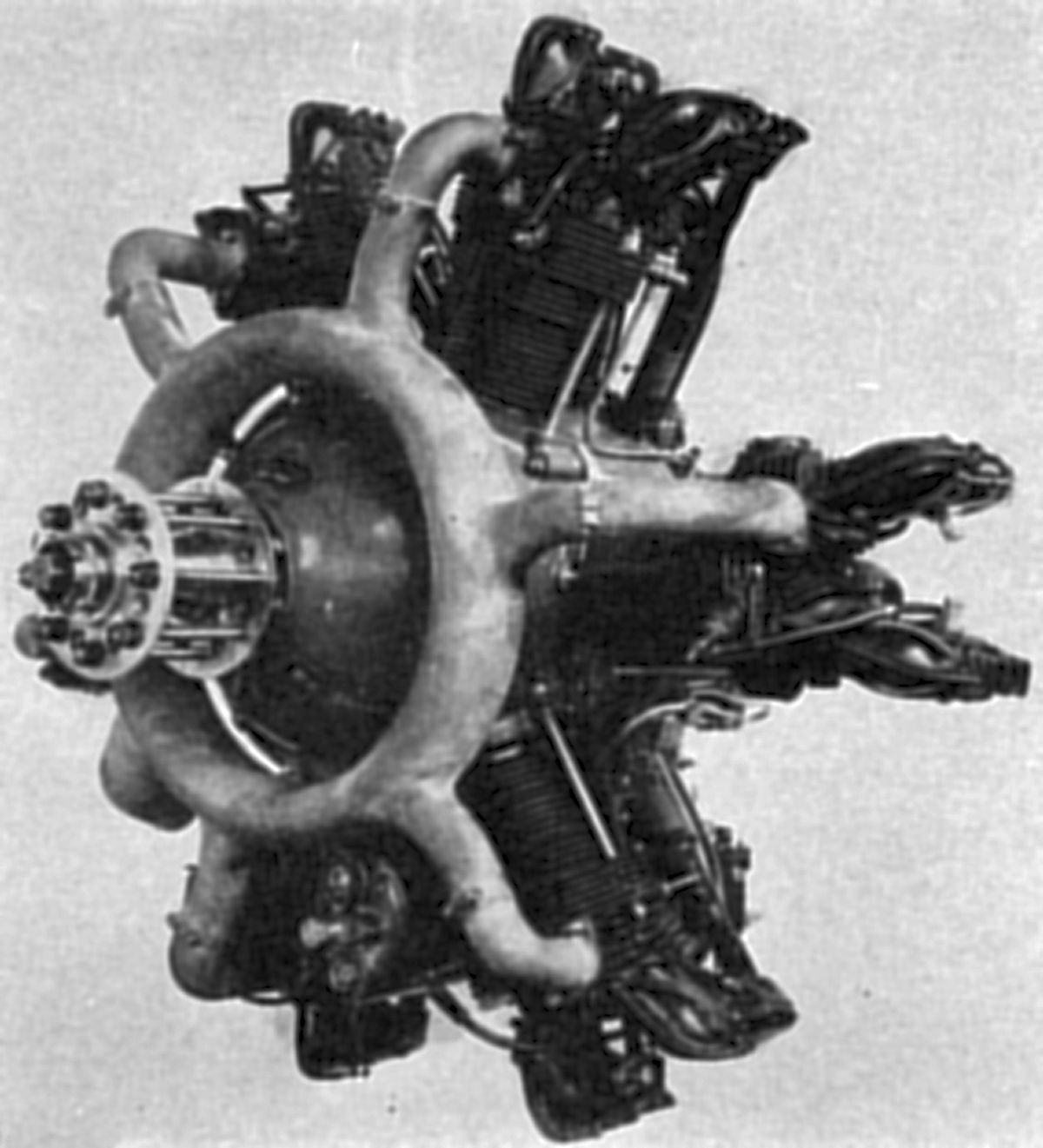 |
| Model 6Ba (A39) |
The 1934 model 6Ba six-cylinder radial was rated 130 hp at 2,200 rpm, weighed 123.83 kg (273 lb), had a 940mm (37") diameter and 860 mm (33.86") length. Excluding detailed refinements, the 9B was practically identical to the 6B model.
 |
 |
 |
| Model 3B (A39) | Model 9Ab (A39) | |
The 3B, a three-cylinder companion to the 6B, appeared in 1933. Model 3B and 6B engine parts were interchangeable to the extent possible. The 3B was rated 60 hp at 2,200 rpm and weighed 78.02 kg (172 lb). Diameter was 925 mm (36.41") and length was 760 mm (29.92").
The 9A, an air-cooled single-row radial nine with bore and stroke the same as the three- and six-cylinder engines, displaced 9.741 l (594.46 in³) and was rated 180 hp at 2,000 rpm. The later 9Ab model, which employed a 6:1 compression ratio and used 85 octane fuel, was rated 185 hp at 2,100 rpm up to 1,000 m (3,280 ft) and weighed 178.26 kg (393 lb). It had a 1,025 mm (40.35") diameter and was 879 mm (34.6") long. It employed a split crankcase, one-piece master rod, a two-piece crankshaft, and articulated connecting rods.
 |
| Model 9B (A39) |
Potez developed the model 9B based on experience with the 9A and 9Ab engines, and with it won the 1933 Deutsch Cup Races. In order to meet the 8 l (488.19 in³) displacement limit rule, the direct-drive 9B was made with a 98 mm (3.858") bore, 117 mm (4.606") stroke, 7.943 l (484.70 in³) displacement and 6:1 compression ratio. Except for a new supercharger geared 11.4:1, the design closely followed the proceeding models. It was rated 300 hp at 2,500 rpm, weighed 169.64 kg (374 lb), and had a 950 mm (37.4") diameter.
The Potez 9Ba and 9Bb engines, developed primarily for the 1934 Deutsch Cup Races, were almost identical to the 9B. The 9Ba delivered 315 hp at 2,550 rpm, while the 9Bb delivered 350 hp at 2,800 rpm. Both engines were 960 mm (37.79") in diameter, 905 mm (35.62") long and weighed 179.62 kg (396 lb). The aluminum alloy cylinder heads were screwed and shrunk onto finned steel barrels. The valve gear was completely enclosed. The aluminum pistons had box-shaped ribs under the head and were fitted with three compression rings above the piston pin and an oil-scraper ring below. The two-piece crankshaft employed a keyed aft split-clamp joint. It was supported by a roller bearing at each crank cheek and a deep-groove ball bearing at the propeller end, together with a plain bushing for oil introduction. The articulated connecting rod system used a one-piece, H-section master rod and tubular link rods operating on knuckle pins held n place by two side flanges on the master rod big end.
The aluminum crankcase had six major sections, two of which were joined in the cylinder plane. A front nose section contained a breather and crankshaft bearings. The rear section contained mixture passages, inlet pipes bosses, and cam-follower guide openings. The double ring cam, each ring with four lobes, was driven through an internal gear. The supercharger housing was mounted at the engine rear, followed by an accessory housing. The supercharger impeller was driven through a torsion shaft and friction clutch that engaged by centrifugal force. Speed multiplication was accomplished through three evenly spaced lay shafts and spur gears.
 |
| 9C-01 (A39) |
The 9C-01, a geared 9Ab version also known as the model 9Abr, was rated 220 hp at 2,500 rpm and weighed 200.49 kg (442 lb). Aside from the spur reduction gears, the structural details were nearly identical to the 9Ab.
 |
| 9E (A39) |
The Potez 9E was an air-cooled supercharged radial nine derived from the 9Ab design. With a 105 mm (4.134") bore, 125 mm (4.921") stroke, 9.741 l (594.46 in³) displacement and 6.0:1 compression ratio, it produced 222 hp at 2,450 rpm at sea level and 240 hp at 2,575 rpm at 2000 m (6,562 ft). It had a 995 mm (39.17") diameter, 1,063 mm (41.85") length and weighed 203.7 kg (449 lb). Fuel and oil consumptions were 0.55 and 0.0175 lb/hp/hr. Improvements over the 9Ab included lubricated valve gear, newer magnetos and carburetors with automatic mixture control. The 9E propeller rotation could be changed in the field; 9E-00 engines rotated clockwise when viewed from the anti-propeller end while 9E-01 engines rotated anti-clockwise.
 |
| Model 12D (A39) |
The 12As (later 12D series) was a water-cooled horizontally-opposed twelves, also known as the Rateau-Potez 12As, whose development was announced in 1932. It was fitted with a Rateau exhaust-driven supercharger, which routed some exhaust from the cylinder tops through a top-mounted turbine. A centrally-located vertical shaft connected the turbine at its upper end to a centrifugal compressor below the crankcase where it received mixture from a bottom-mounted carburetor. A bottom-mounted pump forced water into the cylinder cooling jackets at two points. The water exited around the compressor inlet pipes.
It had a 115 mm (4.528") bore, 120 mm (4.724") stroke, 14.957 l (912.74 in³) displacement and 6.0:1 compression ratio. It was rated 350 hp at 2,400 rpm, and turbosupercharging allowed it to maintain its normal power up to 5,500 m (18,045 ft). It was 1,120 mm (44.1") long, 1,063 mm (42.1") wide, 578 mm (26.77") high and weighed 326.13 kg (719 lb). The six steel cylinder barrels of each bank had cooling fins at their base while the upper ends entered an aluminum alloy cylinder head with an enclosed overhead camshaft. All accessories were driven from the engine front. The cast magnesium-alloy crankcase was split vertically, with symmetrical main bearing saddles in the case. The articulated connecting rods had H-section shanks and the link rods were hinged between the master rod cap flanges. Four rings were fitted to each piston above the piston pin.
In 1936, Potez began a line of auxiliary power units. In the following years, Potez also refined its radial engines, introduced air-cooled in-line inverted fours and sixes, and a geared inverted air-cooled V-8. The company lost its original identity when it was nationalized in 1936.
 |
| Prini-Berthaud (A39) |
Prini-Berthaud
The 1909 French Prini-Berthaud was a water-cooled two-stroke vertical four using crankcase compression. With a 100 mm (3.937") bore, 110 mm (4.331") stroke and 3.456 l (210.0 in³) displacement, it developed 50 hp at 1,400 rpm and weighed 95.8 kg (209 lb). The cylinders were fitted with deeply corrugated sheet-copper water jackets.
Pratt & Whitney
Pratt & Whitney engines have been covered extensively by the AEHS. For further information, please use the home-page search feature.
References
Angle, Glenn D, ed. Aerosphere 1939 (New York, New York: Aircraft Publications, 1940).
Angle, Glenn D, ed. Airplane Engine Encyclopedia (Dayton, Ohio: Otterbein Press, 1921).
Hartman, Par Gérard. Les moteurs Panhard & Levassor.
Image Sources: A39 = Aerosphere 1939; AEE = Airplane Engine Encyclopedia; Flt = Flight Magazine; NARA = U.S. National Archives and Records Administration; UKNA = United Kingdom National Archives.
Send mail to
![]() with questions or comments about this web site.
with questions or comments about this web site.
![]()