Selected Early Engines
N.A.G, Napier, N.E.C., Novus
Compiled by Kimble D. McCutcheon
Published 14 Jan 2023; Revised 21 Jan 2023
N.A.G.
N. A. G. engines were built by the Neue Automobil Gesellschaft in Germany starting in 1912.
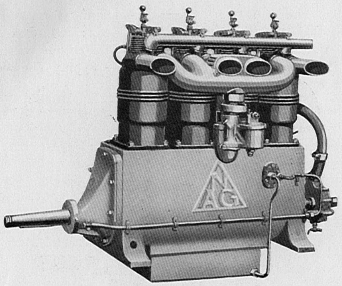
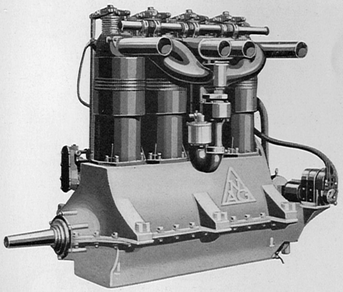
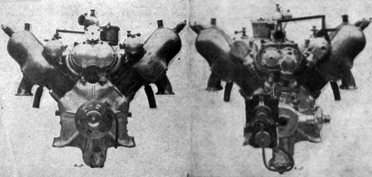
The Model F-1 a was water-cooled in-line four with a 118 mm (4.646") bore, 100 mm (3.937") stroke, and 4.374 l (266.94 in³) displacement. It was rated 55 hp at 1,600 rpm, and weighed 95.7 kg (211 lb).
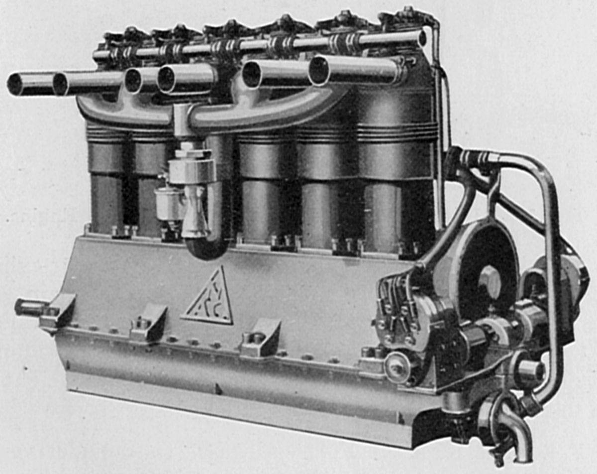
The Model F-2 was a water-cooled in-line four with a 120 mm (4.724") bore and stroke that displaced 5.429 l (331.28 in³). It was rated 55 hp at 1,400 rpm, 60 hp at 1,600 rpm, and weighed 96.2 kg (212 lb). Its cast-iron cylinders with copper water jackets held in place by spring rings were offset from the crankshaft center line. The overhead valves were operated by push rods and rocker arms. Pressure lubrication was used and a magneto furnished ignition. A compression release helped starting.
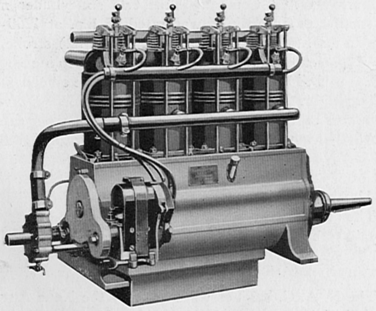
The Model F-3 was a water-cooled in-line four with a 135 mm (5.315") bore, 165 mm (6.496") stroke and 9.447 l (576.50 in³). It was rated 100 hp at 1,250 rpm, weighed 160.1 kg (353 lb), and had a 0.473 lb/hp/hr specific fuel consumption.
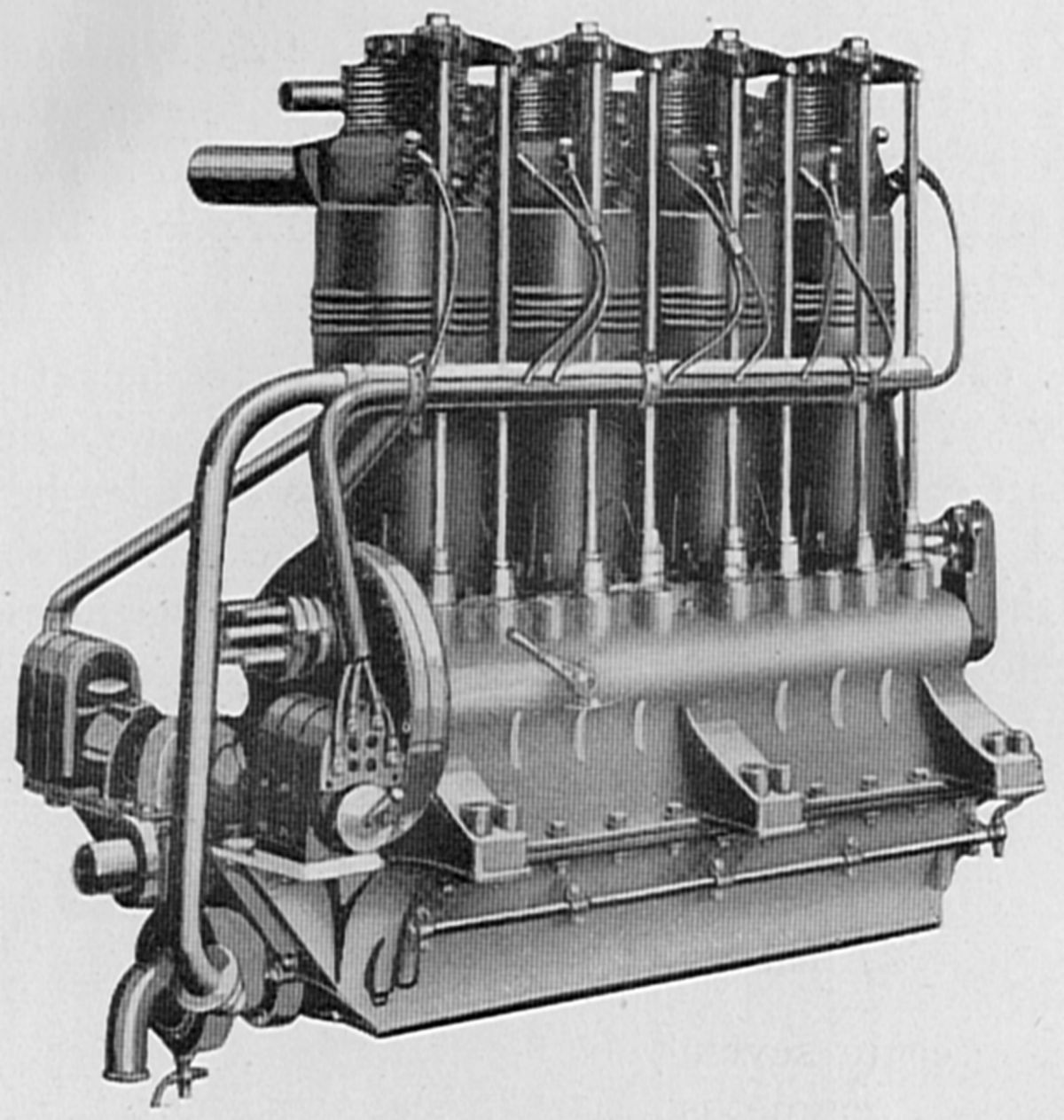
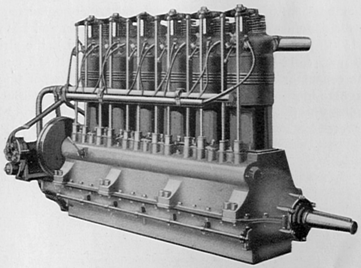
The Model F-4 water-cooled in-line six with a 135 mm (5.315") bore, 165 mm (6.496") stroke and 14.170 l (864.75 in³) displacement. It was rated 150 hp at 1,250 rpm, weighed 229.97 kg (507 lb) with one magneto and no flywheel. The crankshaft was mounted in seven plain bearings and two magnetos supplied ignition.
|
|
|
|
|
|
| N.A.G. F-2 (A39) | N.A.G. F-3 (A39) | N.A.G. F-4 (A39) | |||
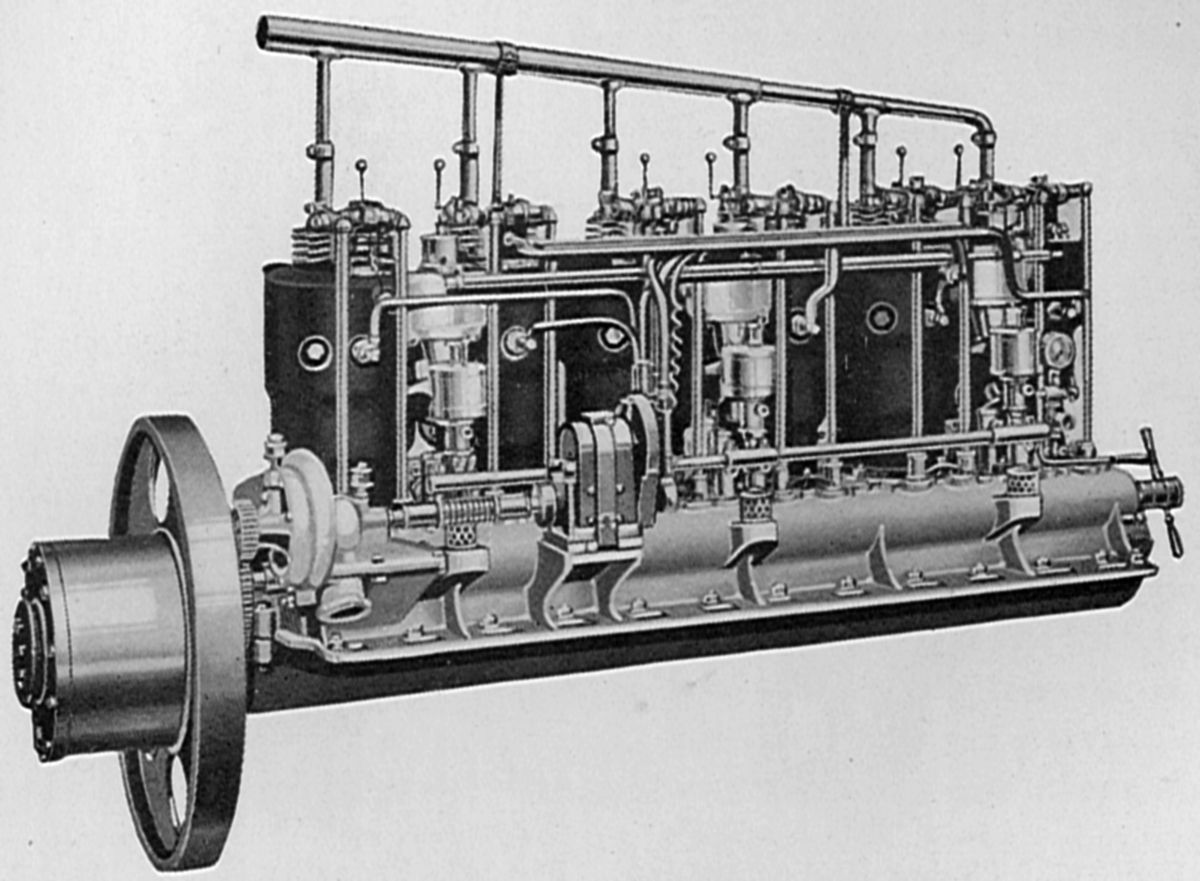
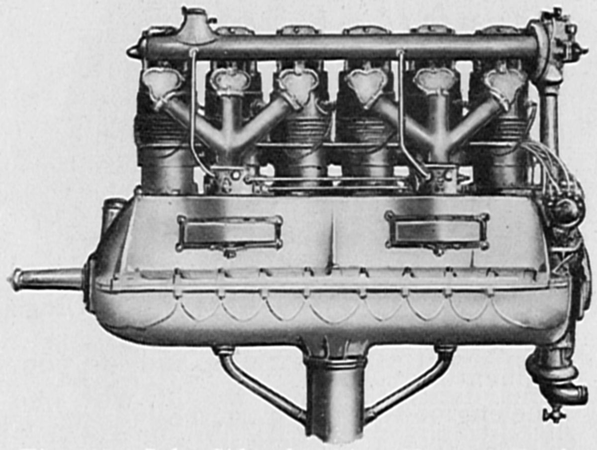
The Model 301, a water-cooled in-line six for dirigible use, had a 150 mm (5.906") bore, 130 mm (5.118") stroke and 13.783 l (841.09 in³) displacement. It was rated 110 hp at 1,100 rpm, 120 hp at 1,300 rpm and weighed 349.3 kg (770 lb), including flywheel. Specific fuel consumption was 0.473 lb/hp/hr. Magneto ignition was employed. A larger water-cooled vertical six producing 185 hp was developed later.
 |
 |
||
| Model 301 (A39) | N.A.G. 185 hp Engine (A39) | ||
Napier
David Napier, who trained as an engineer in Scotland, started a precision engineering and manufacturing company that became D. Napier & Son Limited in 1908. Napier designed steam-powered printing presses, sugar manufacturing centrifuges, lathes, drills, ammunition-making equipment and railway cranes. His son, James, took over the company and after his father's death in 1873, specialized in coin-making machinery, stamp printing and banknote printing equipment. Napier started manufacturing an aircraft engine late in WWI.
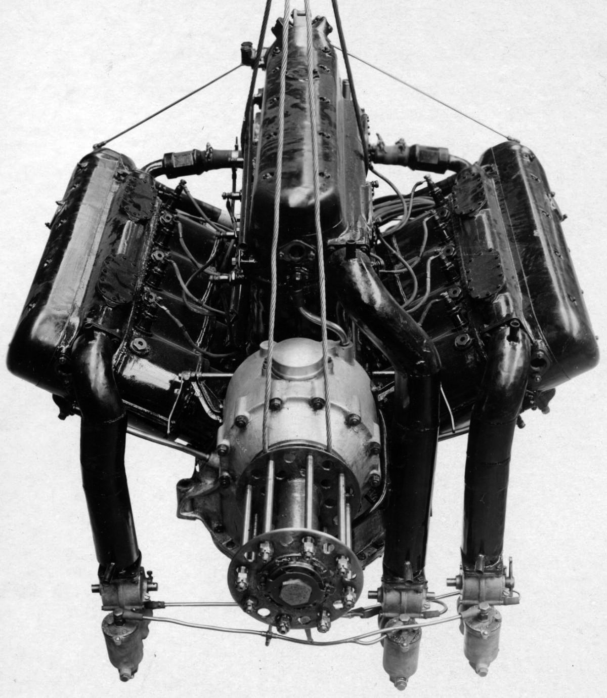
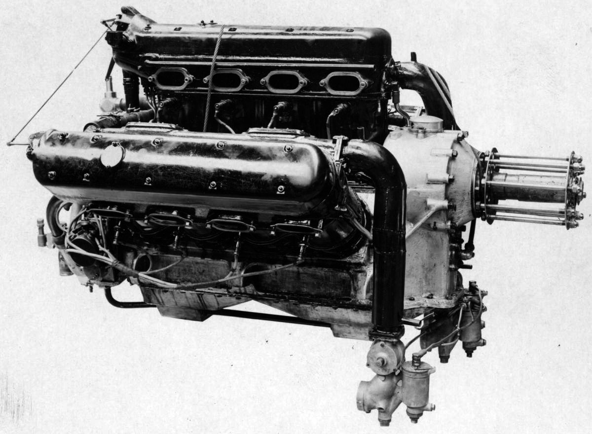
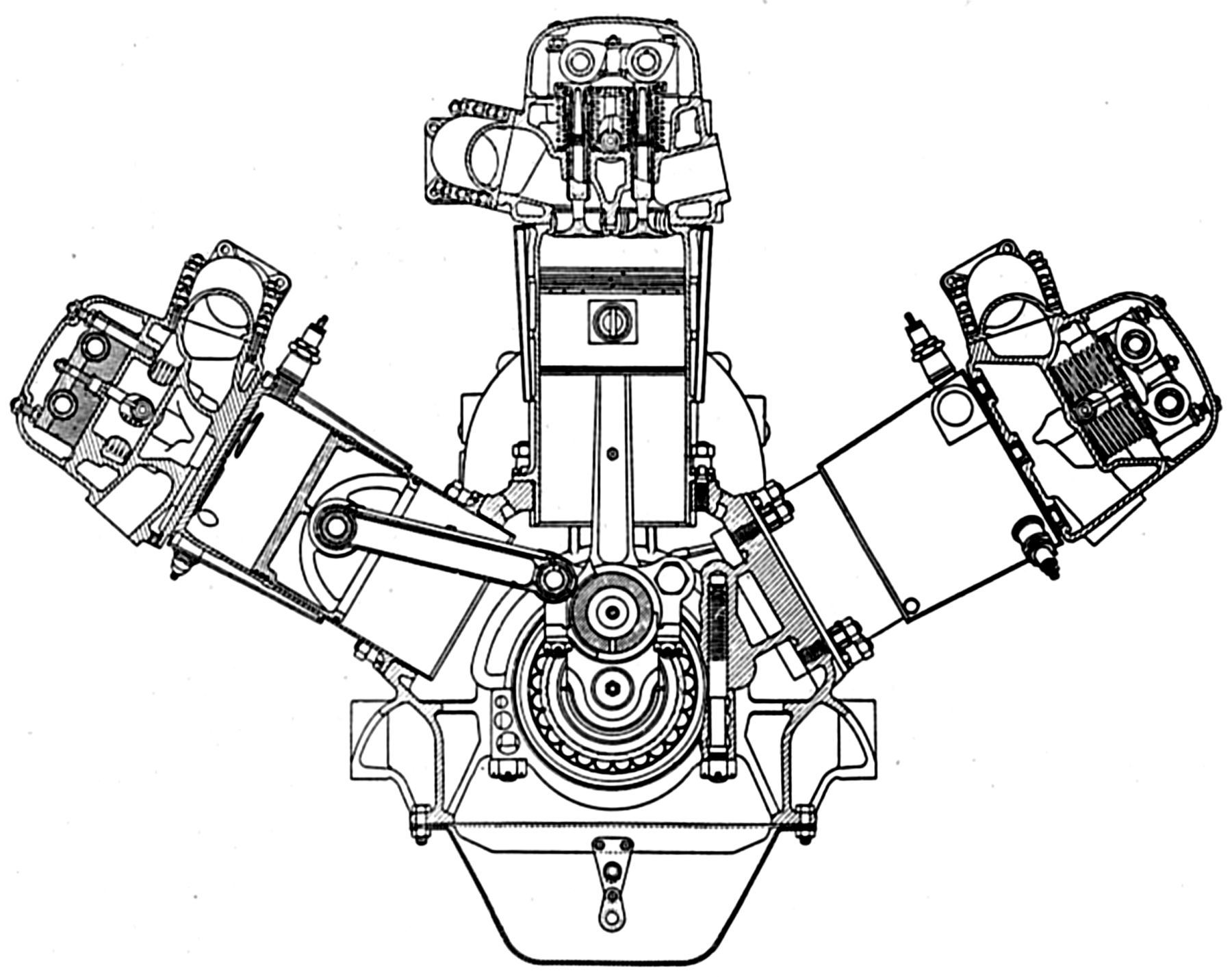
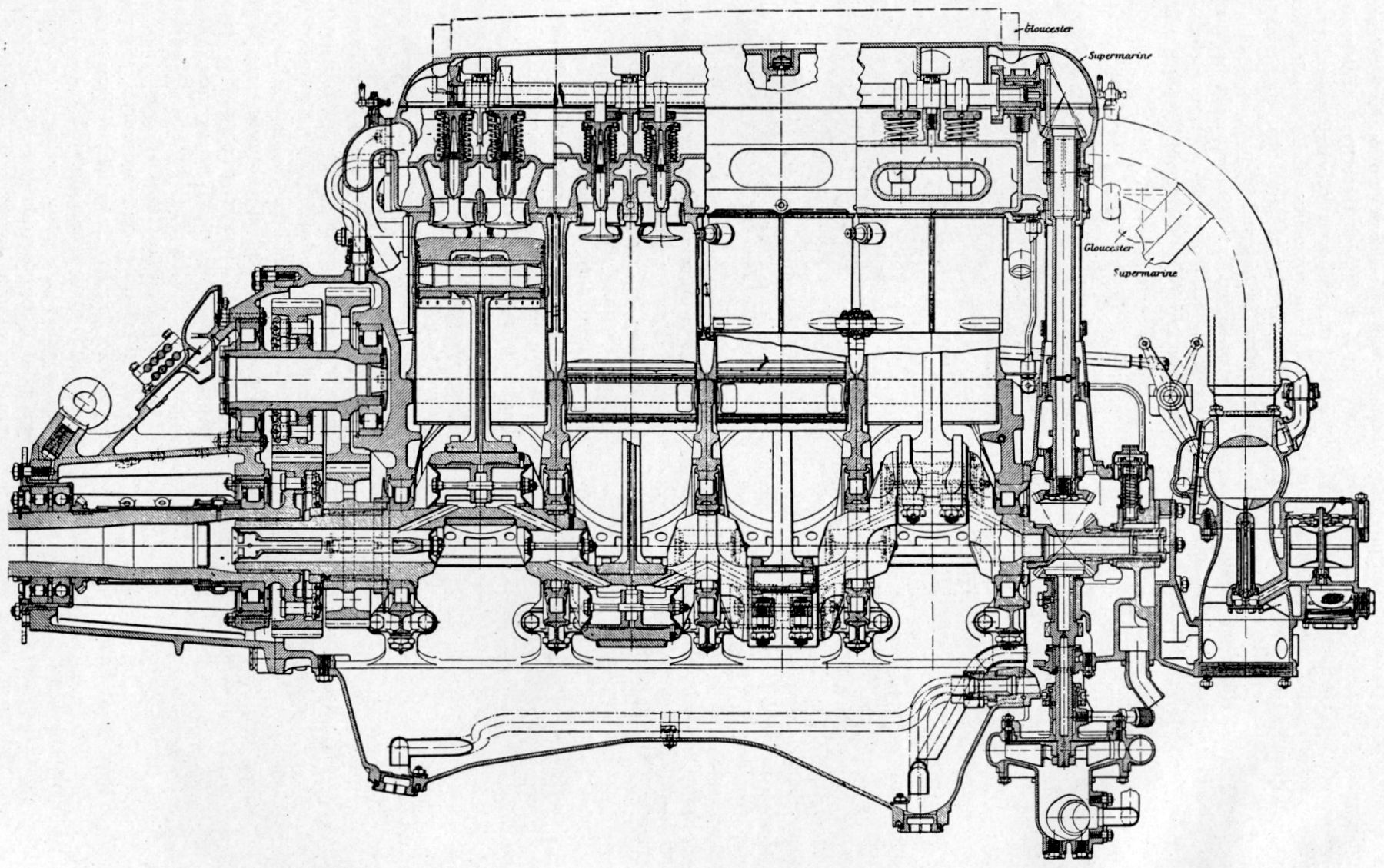
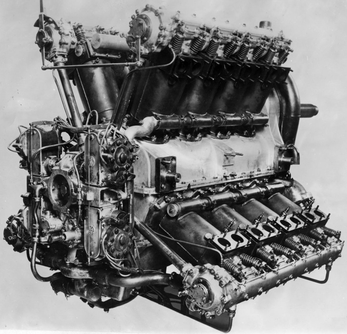
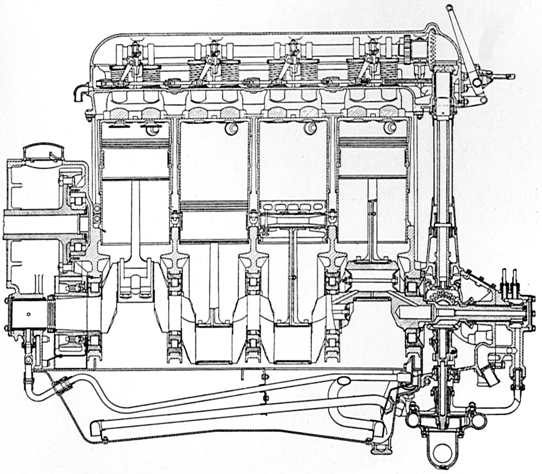
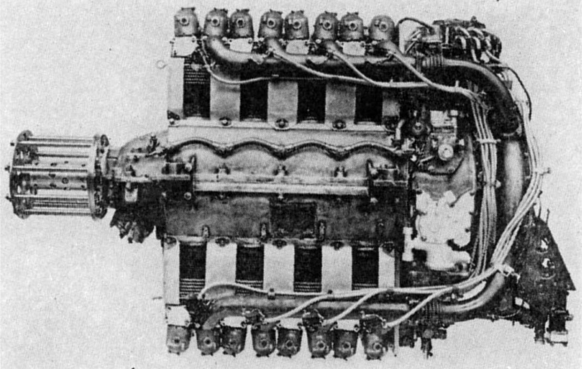
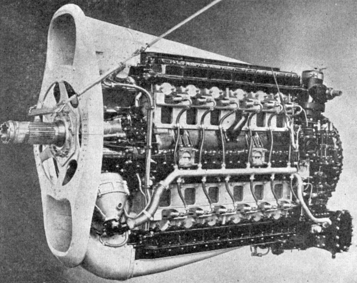
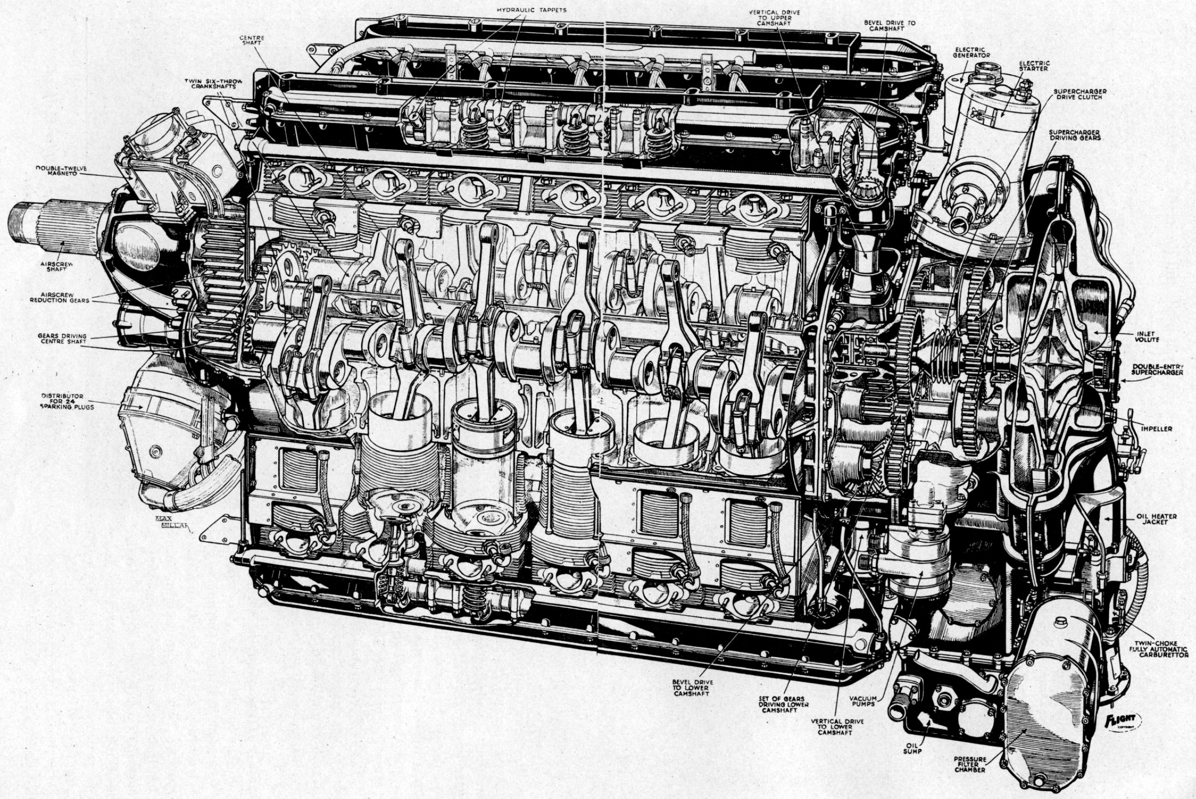
The Napier Lion, a water-cooled 60° W-12, had a 5.500" (139.7 mm) bore, 5.125" (130.18 mm) stroke, and 1,461.13 in³ (23.94 l) displacement. Early Lion engines employed a 5.53:1compression ratio, were rated 450 hp at 1,925 rpm and nearly 500 hp at 2,050 rpm, and weighed 858 lb (389 kg). The Lion was 49.5" (1,257 mm) long, 41.875" (1,064 mm) wide and 36" (914 mm) high. Geared engines had a 3:2 propeller reduction ratio.
The three aluminum alloy cylinder heads incorporated bearings that carried two overhead camshafts driven by bevel and spur gears. These actuated valve tappets and also featured a compression release cam mechanism. The head casting lower portion contained the inlet and exhaust ports, and formed the water jacket upper part. The cylinder barrels were machined separately from steel forgings and were attached to the cylinder head by screwed-in thimbles that served as valve seats. Sheet-metal water jackets were separately welded around each cylinder barrel. Two inlet and two exhaust valves served each cylinder. The inlet valves had a 0.344" (8.74 mm) lift and a 3.55 in² (2,290 mm²) opening area. The exhaust valves had a 0.354" (8.99 mm) lift and a 3.65 in² (2,355 mm²) opening area. The inlets opened 10° late and closed 51° late; the exhausts opened 48° early and closed 10° late. The cams operated directly upon the valves, with a clearance adjustment scheme similar to Hispano-Suiza engines. The four-throw crankshaft ran on five roller bearings. An additional roller bearing, as well as a ball thrust bearing, were used on direct-drive engines, and an additional plain bearing, just outside the driving gear at the propeller end was provided on the geared models.
The H-section master connecting rods with their forked sections for the articulated-rod knuckle pins operated on the center cylinder row. Early link rods had tubular sections; later ones had H-section shanks. Internally ribbed aluminum alloy pistons with three top rings and one bottom ring, the lower two serving as oil scrapers, were used. Cooling water was circulated by a centrifugal pump mounted at the engine rear and driven at crankshaft speed. The pump had three outlets for the separate water connections to each cylinder bank's cooling jackets and cylinder head. Two 12-cylinder Thompson-Houston Type AV-12 magnetos furnished dual ignition; one magneto had a special distributor rotor that was used for starting magneto. Dry-sump lubrication featured one pressure and two scavenging gear pumps.
When run with fuel containing 20% benzol, a 0.504 lb/hp/hr consumption was obtained. Single and duplex Claudel H-C-7 carburetors, having water-jacketed throttles, were fitted. The engine was lubricated with castor oil and consumed 0.037 lb/hp/hr. A normal oil pressure of 45 - 50 psi was maintained at the bearings.
The Lion Series 2, 2A, and 2B were generally similar to the above but the compression ratio was increased to 5.8:1 with corresponding slight increases in maximum powers and economy.
 |
 |
 |
 |
 |
 |
| Napier Lion (AEE, A39, NARA) | |||||
 |
| Napier Lion Series V (A39) |
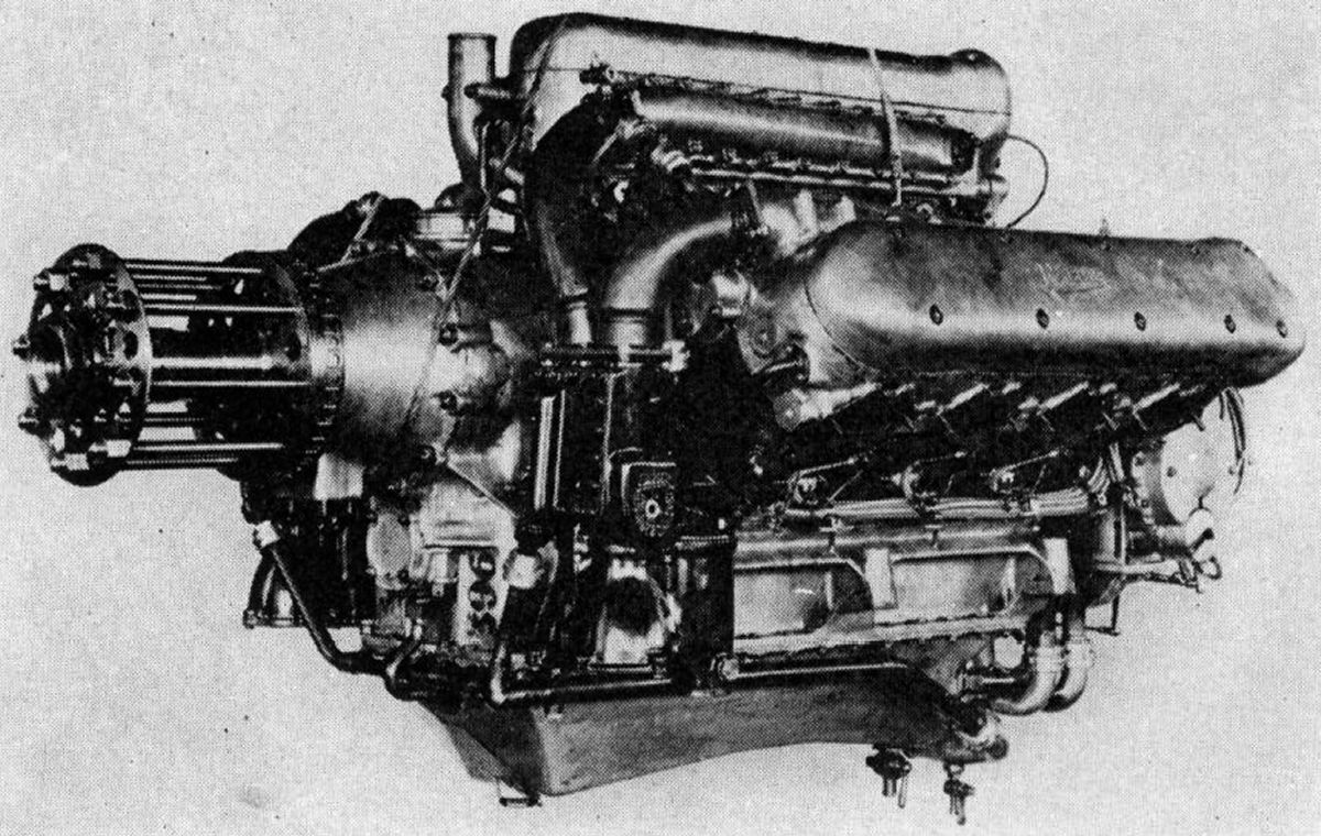
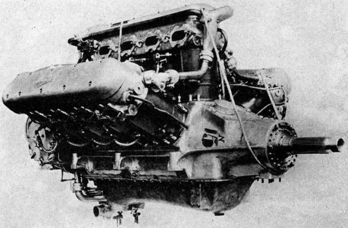
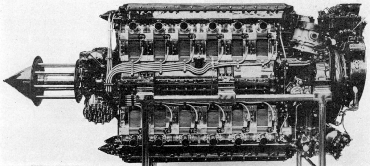
The Lion Series V, which was the standard production engine up until 1928, resembled the earlier models. With a 5.0:1 compression ratio the engine was rated 425 hp at 2,000 rpm and developed 458 hp at 2,200 rpm With a 5.8:1 compression ratio it was rated 450 hp at 2,000 rpm and developed 502 hp at 2,200 rpm. The propeller reduction gear ratio was 3:2 and the dry weight was 940 lb (426.4 kg).
 |
 |
| Napier Series VII Racing Engines(A39) | |
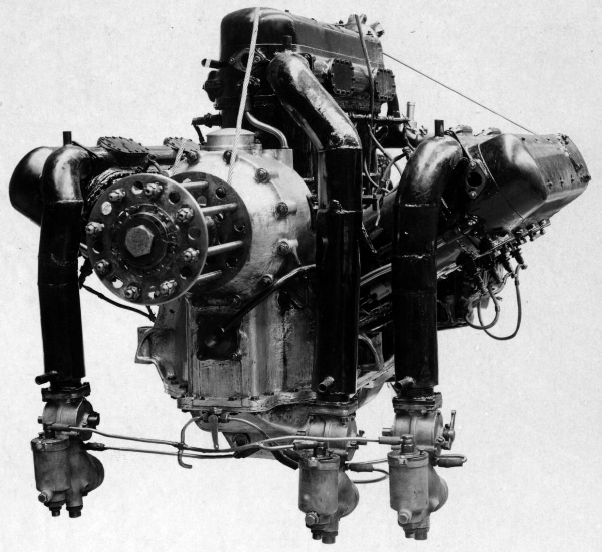
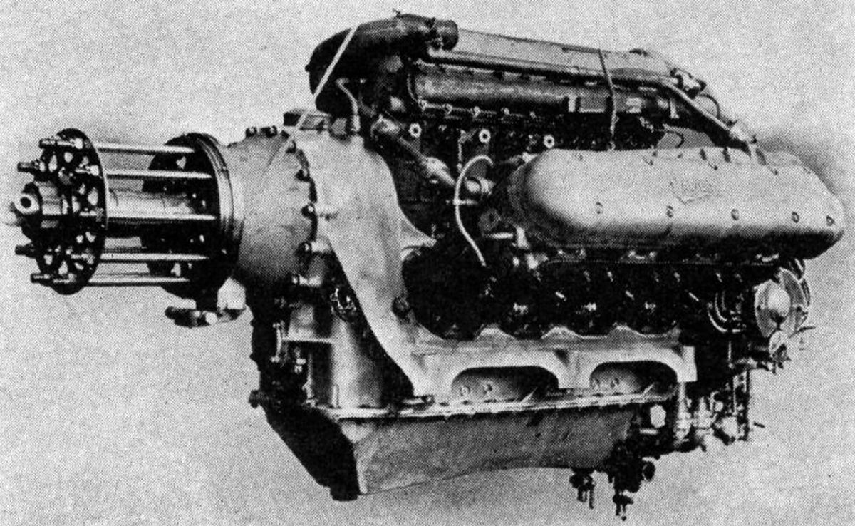
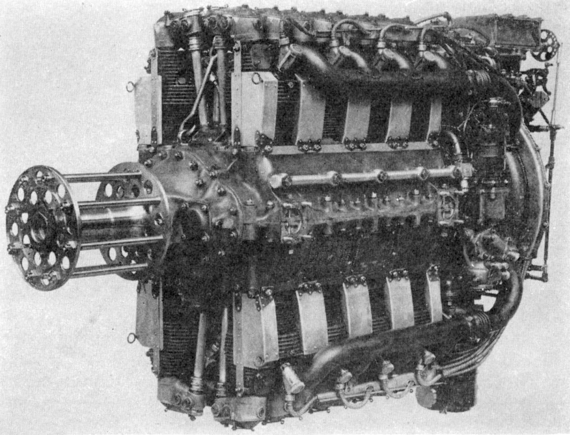
The Lion Series VII A was a direct-drive high-compression engine developed especially for racing airplanes. The principal modifications reduced frontal area and head resistance. Cylinder block height was reduced by shortened connecting rods, and all piping was arranged so that it did not project into the space between cylinder rows. Magnetos were placed at the engine front with their axes parallel to the crankshaft. Pistons were made from Y-alloy forgings and their length was reduced to a minimum. The full-floating piston pins were fitted with aluminum plugs. A second oil-scraper ring was added below the piston-pin, together with a series of drilled holes through the piston walls for draining the increased oil volume splashed upon the cylinder walls. Special plugs in the crankpins trapped the oil contamination. The steel main bearing crankshaft caps had two lugs at each end for bolting to the crankcase sides. The caps tied the engine sides together, greatly relieving the cast magnesium alloy crankcase lower section stress. A 10.0:1 compression ratio was employed, and the fuel was a 25% benzol mixture to which 13 cc of tetraethyl lead per gallon was added. The output was 875 hp at 3,300 rpm. and the weight was 835 lb (378.7 kg).
The Lion Series VII B was exactly the same as the Series VII A except that double reduction gearing consisting of a lay shaft with two gears above the coaxial crankshaft and propeller shafts. The ratio provided by these four gears was 1.306:1. The power developed was 875 hp at 3,300 rpm and the weight was 920 lb (417.3 kg). Length was 66.25" (1,683 mm), width was 38.5" (978 mm), and height was 34.5" (876 mm). This engine became famous by winning the 1927 Schneider Cup race held at Venice, Italy. Some Lion Series VII B engines were fitted with centrifugal superchargers.
 |
| Napier Lion Series VIII (A39) |
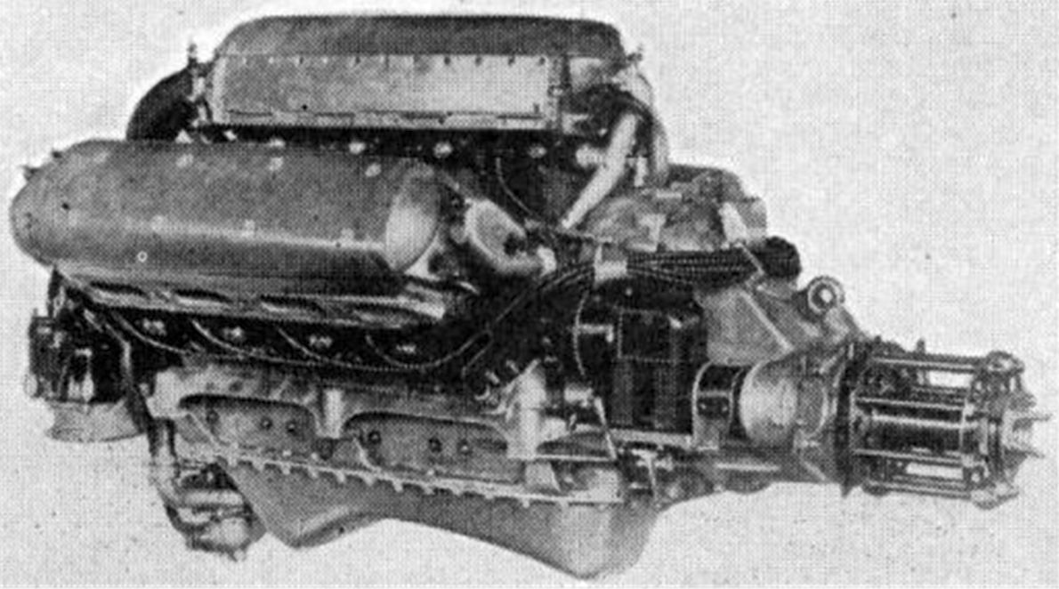
The Lion Series VIII, introduced in 1926, was a direct-drive high-compression engine for installation in high-speed aircraft. The propeller reduction gears were removed, the auxiliary units were altered, and the carburetors were moved to where they did not affect frontal area or interfere with the engine cowling. Rated output was 525 hp at 2,350 rpm and 567 hp at 2,585 rpm. Compression ratio was 6.25:1. Fuel and oil consumptions were 0.527 and .038 lb/hp/hr and weight was 920 lb (417.3 kg). Length was 61" (1,549 mm), width was 42" (1,067 mm) and height was 39" (991 mm).
 |
| Napier Series XI (A39) |
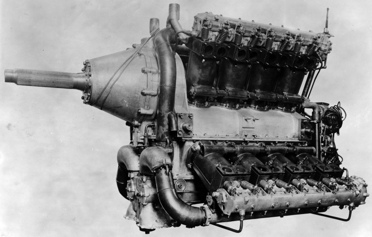
The Lion Series XI superseded the Series V engine and employed a 6.0:1 compression ratio. It was rated 530 hp at 2,350 rpm and delivered 570 hp at 2,585 rpm. The propeller reduction gears had a 1.885:1 ratio. The tractor type engine, complete except for starting magneto, weighed 995 lb (451.3 kg) and the pusher type 1,000 lb (453.6 kg). The gun gear and gas starting distributor added about 10 lb (4.54 kg). Fuel and oil consumptions were 0.53 and 0.03 lb/hp/hr. A water-jacketed triple carburetor was attached to a bracket on the rear cover. Water-jacketed steel pipes distributed the mixture to the cylinder heads.
 |
 |
 |
| Napier Cub (AEE) | ||
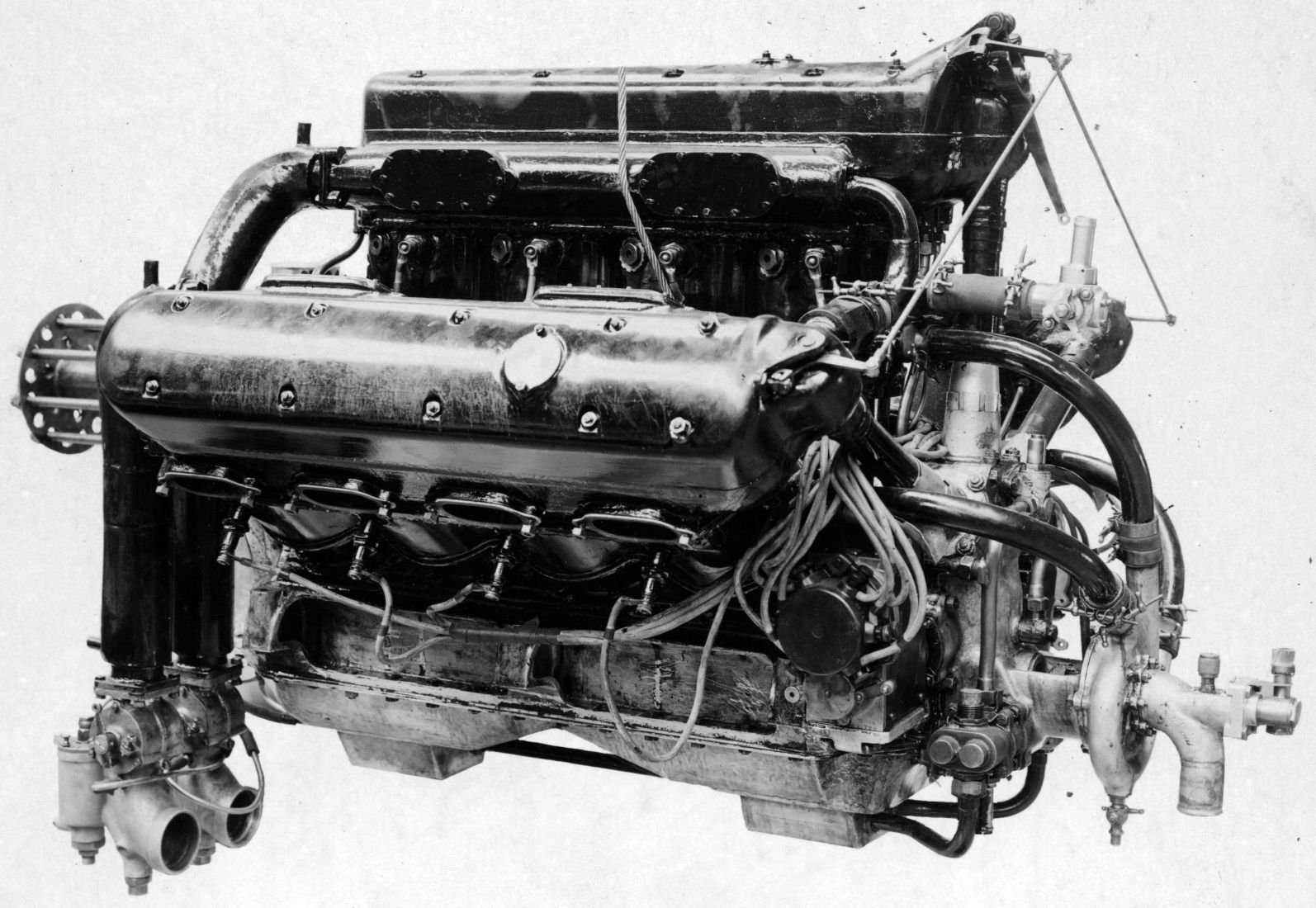
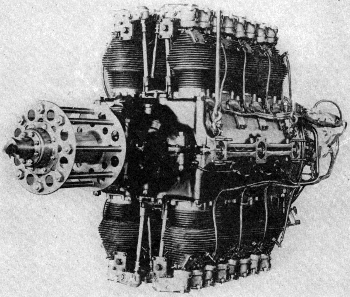
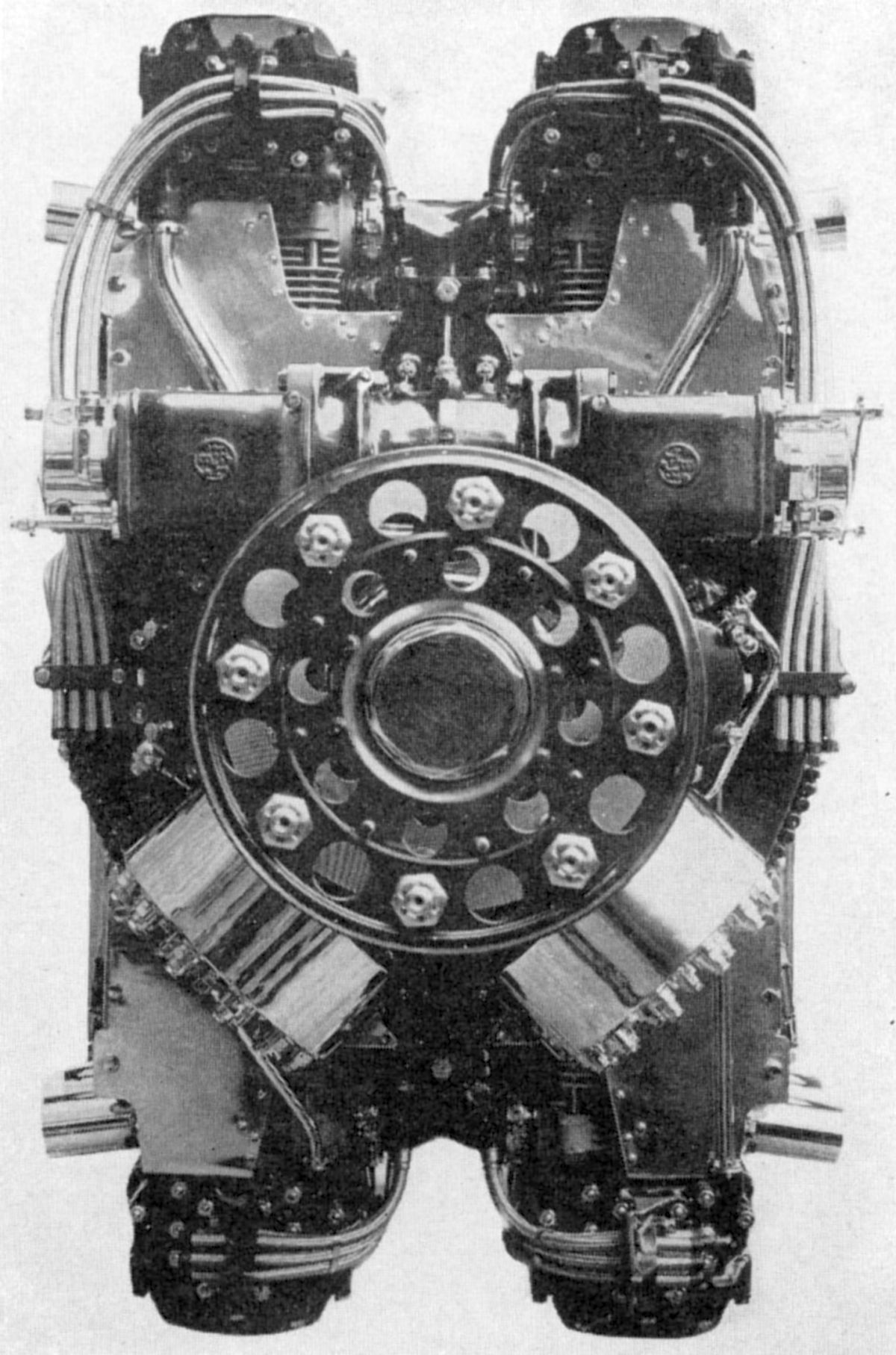
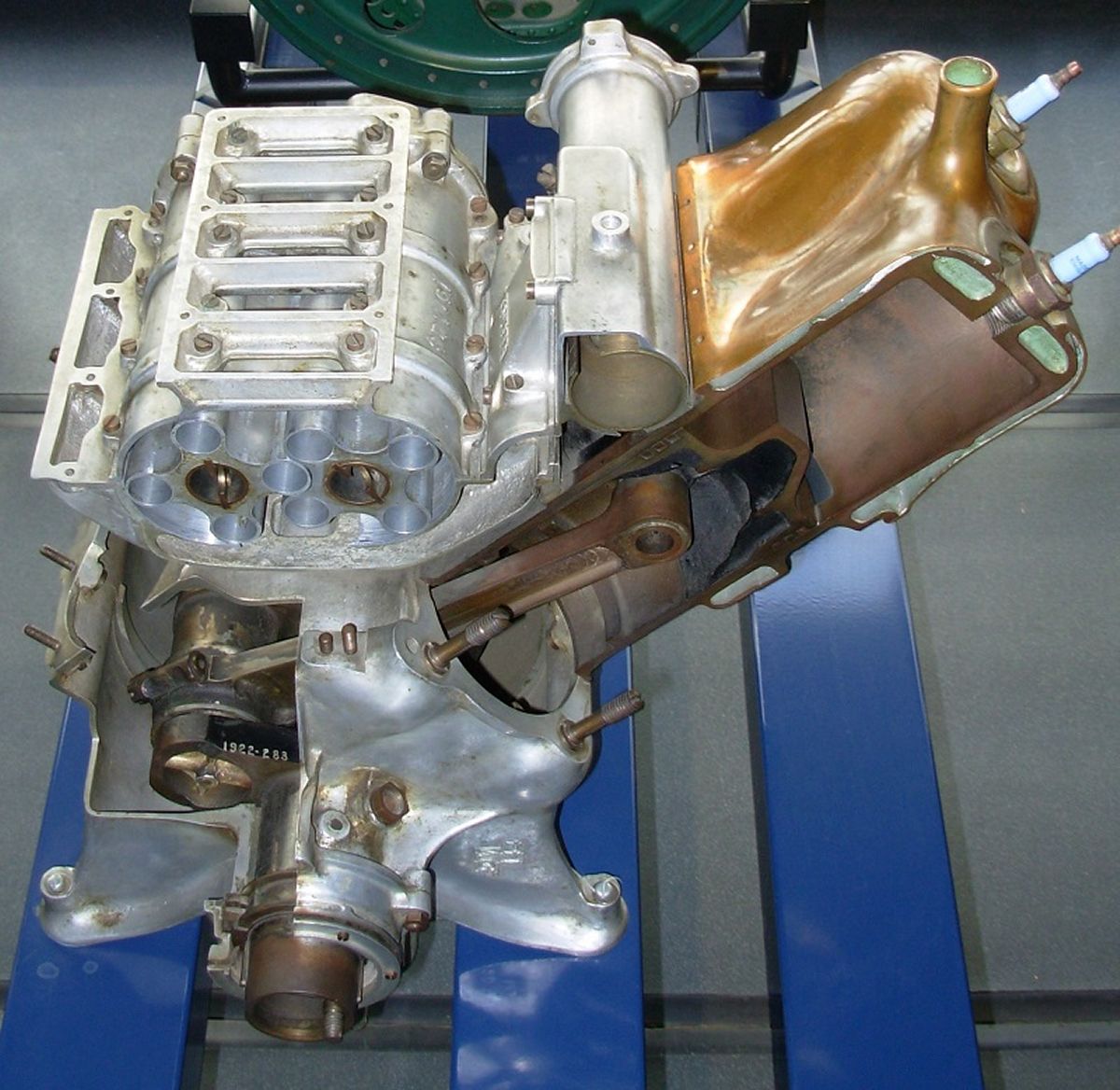
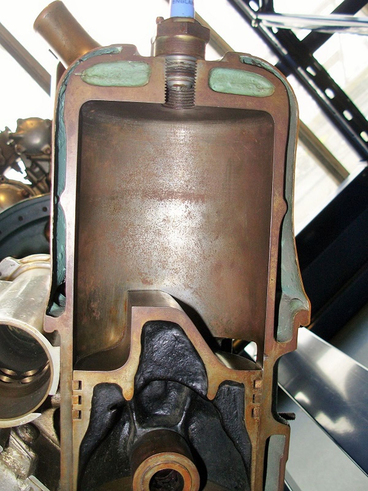
The Napier Cub was designed in 1921 by Arthur John Rowledge, MBE, FRS (30 Jul 1876 – 11 Dec 1957), who also designed the Lion. The Cub was a water-cooled X-16 with its top 4-cylinder rows arranged 26.25° from vertical and its bottom rows 63.75° from vertical, forming two 90° Vees on each side of center. Its bore was 6.25" (158.75 mm), stroke was 7.5" (190.5 mm), and displacement was 3681.55 in³ (60.33 l). Its rated output was 1,000 hp at 1,800 rpm and it developed 1,074 hp at 2,000 rpm . Compression ratio was 5.3:1 and its fuel and oil consumptions were 0.52 and .035 lb/hp/hr. Dry weight was 2,450 lb (1,111.3 kg). Length was 71.8125" (1,824 mm), width was 57" (1,448 mm) and height was 64.25" (1,632 mm). Spur reduction gearing provided a 2.04:1 ratio. The propeller shaft was carried on two roller bearings, and a large double ball thrust bearing permitted the engine to be used either as a tractor or as a pusher. Four magnetos at the engine rear, two upright and two inverted provided dual ignition. A gas pressure system and distributing mechanism was used for starting. Mixture was supplied by two duplex carburetors whose bodies were water jacketed. The steel pipes connecting the carburetors to the cylinder head induction manifolds were also water jacketed.
The individual cylinders were machined from steel forgings and surrounded with welded-on sheet-steel water jackets. Two inlet and two exhaust valves in each cylinder were operated through rocker arms by an overhead camshaft carried in a detachable aluminum alloy housing. The camshafts were driven from the crankshaft by shafts and bevel gears, and the entire camshaft mechanism was enclosed. Cooling water was supplied to the cylinders by a centrifugal pump with four outlets, one for each bank. This pump was mounted at the engine's lower aft end and driven at 1.5 times crankshaft speed. The four-throw, single-plane crankshaft was machined from a solid steel forging and supported by five large roller bearings. A large plain bearing at the forward end, just ahead of the propeller reduction gears, resolved gear loads. The articulated connecting rods included master rods, which operated in the upper cylinder rows, were made with forks at the big ends for receiving the link rods and knuckle pins. The master rod big-end bearings were white-metal lined. Each of the sixteen aluminum-alloy pistons was fitted with two compression rings and two oil-scraper rings, as well as a full-floating piston pin. A dry-sump gear-type lubrication system, which included two scavenging and one pressure pump, provided oil under pressure.
The Rapier, an air-cooled vertically-opposed H-16 was introduced during 1930. Series I Rapiers were rated at 300 hp and weighed 640 lb (290.3 kg). The Series II (Model E.95) Rapier was rated 305 hp at 3,500 rpm and 10,000 ft; its maximum output was 355 hp at 3,900 rpm and 10,000 ft. Propeller reduction gear ratio was 2.5625:1 and weight was 710 lb (322 kg). Bore and stroke were 3.5" (88.9 mm), resulting in a 538.78 in³ (8.83 l) displacement. Compression ratio was 6.0:1. Guaranteed fuel and oil consumptions were less than 0.616 and 0.035 1b/hp/hr. Length was 55.25" (1,403 mm), width was 20.75" (527 mm), and height was 35.25" (895 mm).
The Rapier Series IV was rated 325 hp at 3,500 rpm and 385 hp at 3,900 rpm. Dry weight was 726 lb (329.3 kg). Fuel and oil consumptions were 0.604 and 0.033 lb/hp/hr.
The Rapier Series V was rated 305 – 315 hp at 3,500 rpm and 10,000 feet and 330 - 340 hp at 4,000 rpm and 13,000 feet. Weight was 720 lb (326.6 kg). The blower gear ratio was 6.33:1, compression ratio was 7.0:1, length was 57.37" (1,457 mm), width was 23.37" (594 mm) and height was 36.00" (914 mm).
The Rapier Series VI passed the Air Ministry type tests in 1935. With the compression ratio raised to 7.0:1, the Series VI had was rated 350 - 370 hp at 3,650 rpm at 4,700 feet. At 4,000 rpm, it produced 380 - 395 hp at 6,000 ft. The blower gear ratio was 5.27:1. The propeller reduction gear ratio was 2.5625:1. Dry weight was 707 lb (320.7 kg), length was 56.625" (1,438 mm), width was 23.375" (594 mm), and height was 36.00" (914 mm). The fuel and oil consumptions were 0.427 and 0.0315 lb/hp/hr.
 |
 |
 |
 |
| Series I | Series II, IV | Series VI | |
Rapier cylinder barrels were made from machined-all-over steel forgings that were screwed into cast aluminum alloy cylinder heads contained inlet and exhaust passages, as well as support for the valve actuating mechanism. Each cylinder had one inlet and one exhaust valve with double coil springs, operated via push rods and rocker arms from camshafts in the crankcase. The entire valve mechanism was enclosed. Pistons were made from aluminum-alloy forgings, and provided with hollow piston pins. Early engine pistons were fitted with three compression rings and one oil scraper ring; later models used two compression rings.
The crankshafts were machined from solid steel forgings and supported in six large-diameter plain lead-bronze bearings. Case-hardened steel spur gears reduced the propeller shaft speed. The propeller shaft was carried on a special roller bearing at its rear and a front ball thrust bearing. Early Rapier engines used articulated connecting rods with master rods in the top port and bottom starboard cylinders. Separate steel-backed lead bronze bearing shells lined the crankpin ends, and phosphor-bronze bushings were fitted to the small ends. Series V and VI engines employed fork-and-blade connecting rods with steel-backed lead-bronze-lined bearings in the fork rod. Blade rods oscillated on its outer surface. Looking from the engine rear, the first and third blade rods were attached to top cylinders and the second and fourth blade rods to bottom cylinders.
The crankcase was made in halves and enclosed the propeller reduction gearing, two crankshafts, two camshafts, and the gun synchronizer gear. Aluminum alloy was used in the earlier engines and magnesium alloy in the Series V and VI engines. The timing gear case, attached to the engine rear, carried the camshaft, magneto, and oil pump drive gears. Two special eight-cylinder two-point magnetos were mounted vertically on the timing-gear case, and were provided with special distributors to facilitate hand starting. The magneto controls were interconnected, and the ignition cables were metal braided.
The full-pressure lubrication system employed two scavenging and one pressure pump. A Tecalemit filter was fitted between the pressure pump and engine, and two filters for the scavenged oil were in the oil sump. The reduction gears were lubricated by oil spray from a jet connected to the high-pressure system, oil from which was bypassed through a relief valve to the low-pressure system serving the rest of the engine. Adjustable pressure-relief valves were incorporated in both high and low-pressure systems.
A centrifugal supercharger was attached to the engine rear and its impeller was driven from the propeller shaft via a quill shaft, lay shafts and spur gears. Friction disc clutches in the layshafts protected against torsional vibration and sudden speed changes. The supercharger was situated between the inlet manifolds and the special Napier Claudel-Hobson carburetor. The carburetor was oil-jacketed near its throat, and included an altitude-control cock connected with the throttle control and arranged to furnish the required control under all boost conditions. Fuel was delivered to the carburetor by a gear pump. For starting, fuel was pumped into the cylinders and ignited by a hand-starting magneto operated through the distributors. A gas distributor provided an alternate starting method. The hand-turning gear had an 8.28:1 ratio. Baffle plates partly surrounding the cylinders served to direct air circulation.
The Javelin Model E.97, introduced in 1932, was an air-cooled inverted inline six with a 4.5" (114.3 mm) bore, 5.25" (133.35 mm) stroke and 500.98 in³ (8.21 l) displacement with a 5.3:1 compression ratio. Its normal output was 150 hp at 2,000 rpm, and its maximum output was 170 hp at 2,300 rpm. Dry weight was 410 lb (186 kg), length was 58.5" (1,486 mm), width was 26" (660 mm), and height was 31.5" (800 mm). The cylinders were made by screwing steel barrels into separate cast aluminum alloy heads. Each cylinder was attached to the crankcase by eight studs. Two vertically-positioned valves in the heads were operated directly by a completely enclosed camshaft driven through a vertical shaft and gears at the engine rear. The trunk-type aluminum-alloy pistons were fitted with two compression rings and one oil-scraper ring, all above the large-diameter hollow piston pin. The H section steel connecting rods had white-metal-lined big ends. The six-throw crankshaft was carried in eight white-metal-lined plain bearings, and a deep-groove radial ball bearing resolved propeller thrust loads. Seven of these bearings were supported in the light-alloy crankcase by individual aluminum alloy caps, while the eighth bearing was supported in an end casing. Two Claudel-Hobson carburetors furnished the mixture, and two high-tension magnetos firing dual K.L.G. spark plugs per cylinder supplied ignition. A pressure pump driven off the camshaft vertical drive shaft supplied lubrication and two scavenger pumps returned oil to an external tank. Pads on the crankcase sides were used for mounting. Deflectors directed cooling air around the cylinders.
The Javelin Series III and III A had a 4.5" (114.3 mm) bore, 5.5" (139.7 mm) stroke, 524.84 in³ (9.58 l) displacement and 5.3:1 compression ratio. Normal rated output was 160 hp at 2,100 rpm and 172 hp at 2,325 rpm. Dry weight was 420 lb (190.5 kg). Guaranteed fuel consumption was not over 0.57 lb/hp/hr and oil consumption ranged was 1.5 - 3.5 pt/hr. Length was 64.25" (1,632 mm), width was 19.5" (495 mm) and height was 34.5" (876 mm).
The Culverin was a licensed-built Junkers-type liquid-cooled opposed-piston vertical six-announced in 1934. With a 4.75" (120.65 mm) bore and 8.25" (209.55 mm) stroke it displaced 1,754.3 in³ (28.75 l). Its output was 720 hp at 1,700 rpm and its propeller reduction gear ratio was 1.4419:1. Dry weight was 1,785 lb (809.7 kg). The Cutlas was a smaller Culverin version that produced 550 hp.
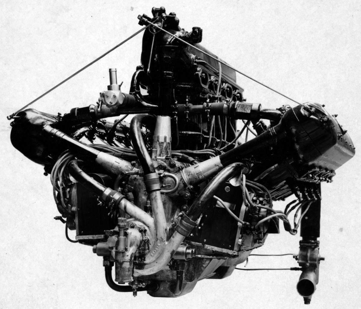
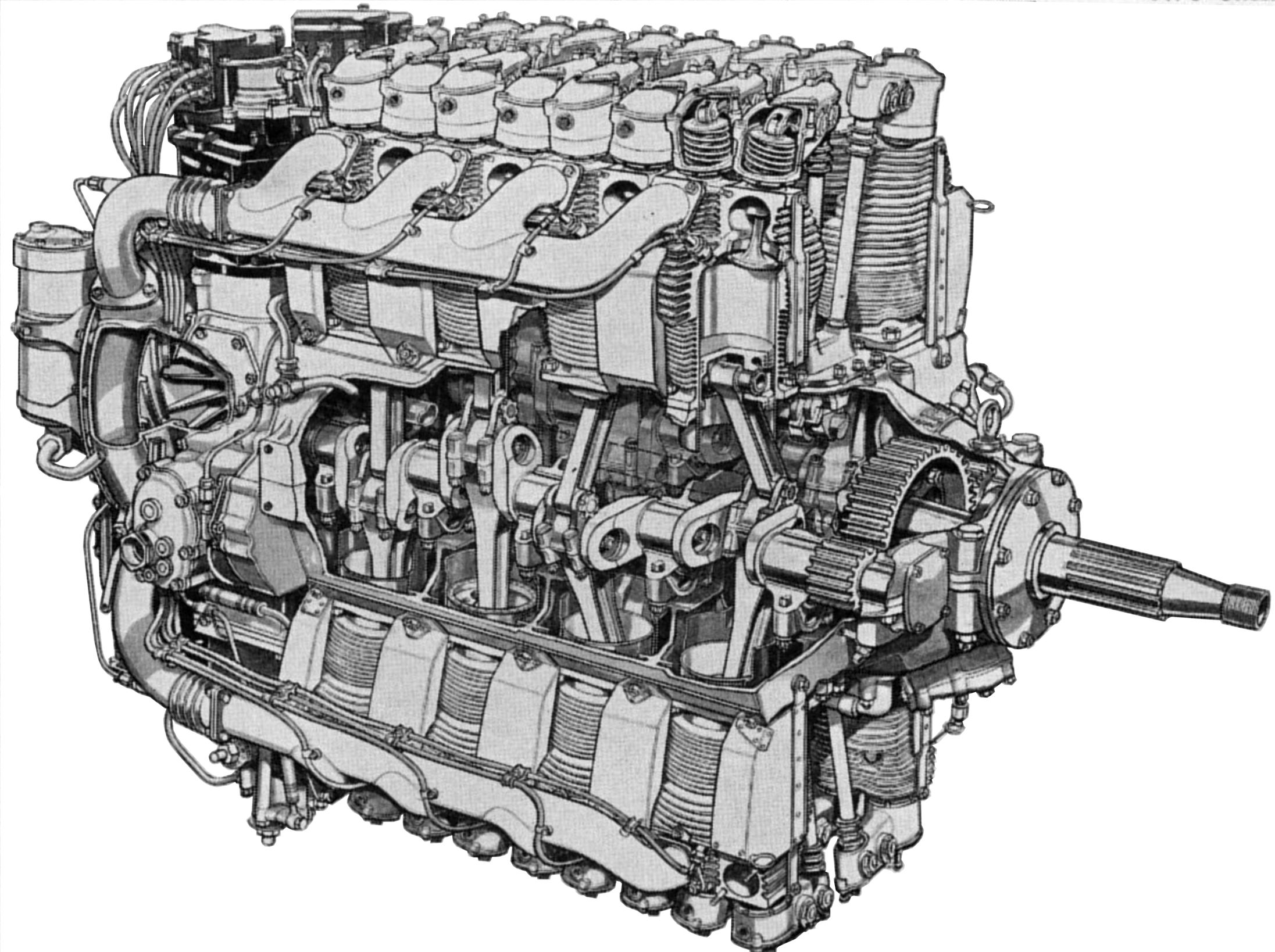
The Dagger was an air-cooled vertical H-24 designed by Frank Halford and introduced in early 1935. It shared many Rapier design elements. With a 3.8125" (96.84 mm) bore, 3.75" (95.25 mm) stroke, 1,027.43 in³ (16.84 l) displacement and 7.15:1 compression ratio, it produced 650 hp. The 2.69:1 spur propeller reduction gear coupled the two crankshafts, which were machined from solid steel forgings and carried on eight large- diameter plain lead-bronze bearings. The fork-and-blade connecting rods contained lead-bronze-lined steel shells upon which the blade rods oscillated. Blade rods were located on top in the front three starboard-row cylinders and in the rear three port-row cylinders. The two-piece aluminum alloy crankcase was split horizontally. A detachable nose piece provided a reduction gears cover and housing for magneto and distributor drives. An oil sump attached underneath the timing gear case, contained the single pressure and dual scavenging oil pumps, the oil-relief valves, and the scavenging pump filters. Two Tecalenlit filter elements were arranged in tandem between the pressure pump and engine.
The cylinder barrels were machined from steel forgings, and the cast aluminum alloy heads contained inlet and exhaust ports. The fully enclosed valve mechanism consisted of one inlet and one exhaust valve per cylinder, each fitted with double coil springs and operated by hydraulic rockers. The forged aluminum-alloy pistons were fitted with two compression rings and one oil-scraper ring. The rear-mounted centrifugal supercharger featured automatic boost control. Its impeller was driven via a quill shaft from the propeller shaft through a lay shaft and spur gears. A differential gear balanced the supercharger drive, and a disc friction clutch mitigated torsional vibration and sudden speed changes. A special Napier Claudel-Hobson down-draft carburetor, with oil jackets around the intake volute and throat, was mounted above the supercharger. Fuel was supplied to the carburetor by a starboard-mounted gear pump driven by a cross shaft. Two magnetos, with separate 24-point distributors, supplied ignition; all four units were driven from the propeller shaft. Each magneto was timed by an automatic advance unit, and the entire ignition system was bonded and grounded to eliminate radio interference.
Dagger Series II engines were rated 670 - 695 hp at 3,500 rpm and 10,000 feet, and 725 – 755 hp at 4,000 rpm and 12,250 feet. Dry weight, less propeller hub, generator, air compressor or gun gear, was 1,305 1b (592 kg). The Dagger Series II was 79.75" (2,026 mm) long, 22.5" (572 mm) width , and 45.125" (1m146 mm) high. Its supercharger impeller gear ratio was 6.47:1. When the engine was producing 475 hp at 3,500 rpm its specific fuel consumption was 0.450 lb/hp/hr.
Dagger Series III engines were rated 700 - 725 hp at 3,500 rpm and 3,500 feet, and 780 - 805 hp at 4,000 rpm and 5,000 feet. Its supercharger gear ratio was 5.04:1. This engine weighed 1305 lb (592 kg). The propeller hub added 26 lb (11.8 kg), generator 22.5 lb (10.2 kg), air compressor 4.75 lb (2.2 kg), and a gun gear of 2.5 lb (1.1 kg). It was 80" (2,032 mm), width 23" (584 mm), and height 45.125" (1,146 mm). When producing 580 hp at 3,500 rpm, fuel and oil consumptions were 0.461 lb and 0.026 lb/hp/hr.
The Dagger Series VIII (E.108) engine appeared in 1938. This engine had a different accessory layout than earlier Daggers and incorporated a variable-pitch propeller governor drive. The propeller shaft was raised and more closely pitched fins provided greater cooling surface. Rated output at 9,000 feet was 890 - 925 hp at 4,000 rpm and 1,000 hp at 4,200 rpm and 8,750 feet with 5 lb boost. Maximum for sea level takeoff at sea level was 955 hp at 4,200 rpm with 6 lb boost. Compression ratio was 7.5:1 and 87 octane fuel was used. Fuel consumption at maximum sea level cruising conditions was 66.5 gph. The propeller reduction gear ratio was 3.2468:1. It was 73.875" (1,876 mm) long, 26.75" (679 mm) wide, and 47.8125" (1,214 mm) high. Dry weight, including fuel pump, propeller control unit, oil filters, cylinder baffles and ignition shielding, was 1390 lb (630.5 kg). Drives were provided for air compressor, 500-watt generator and vacuum pump. The rear-mounted double-entry centrifugal supercharger was driven from the propeller shaft via a quill shaft, spur gears and a torque overload on the impeller spindle. The special S. U. carburetor attached beneath the supercharger was a twin-venturi, fully-automatic with a two-position mixture control and a four-stage boost control. The venturis and throttle valves were oil heated. Except for detailed refinements and the changes mentioned above, the Dagger Series VIII closely followed the Series III design.
During WWII, the sleeve-valve H-24 Napier Sabre became the world's most powerful engine, developing 2,200 – 3,500 hp. This engine is covered in separate articles.
 |
 |
 |
 |
| Napier Dagger Series III (A39) | Napier Dagger Series VIII (A39) | ||
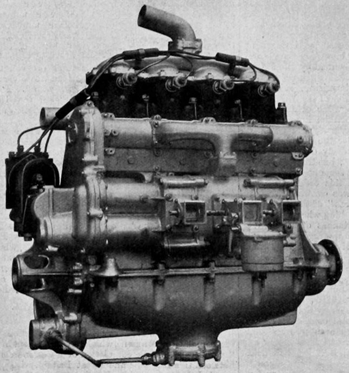
N.E.C.
The New Engine Company, Ltd. (N. E. C.) built two-stroke/cycle engines in Acton, London, England between 1909 to 1912. These were developed from automobile engines designed by George Frederick Mort (c1874 – 1918), an automobile and engine pioneer. Most were water-cooled vertical or V-types with inlet ports on one cylinder side and exhaust ports on the other. The pistons had deflectors near the inlet side that diverted the entering mixture to help scavenge exhaust gasses. As explained in the 9 Oct 1909 British (GB 1909 23,104) and 1 Oct 1910 U.S. (US 1,021,697) patent applications, three tandem crankshaft-driven Roots blowers were arranged so that the outer blowers delivered fresh scavenging air through cast-in crankcase passages to the piston inlet ports. The center Roots blower delivered a rich fuel/air mixture to the interior of a ball-bearing-mounted rotating barrel valve driven at crankshaft speed. The barrel valve outlet ports also opened into the inlet ports. In operation, the cylinder exhaust ports opened first, allowing partial exhaust pressure blow down. The inlet ports then opened, but only pure pressured air flowed through the inlet ports until the cylinder had been mostly cleared of exhaust. The barrel valve then opened to supply the rich mixture to the inlet port under pressure from the center Roots blower. All ports closed simultaneously, after which the fresh air and rich mixture finished mixing, forming a suitable mixture strength to support combustion.
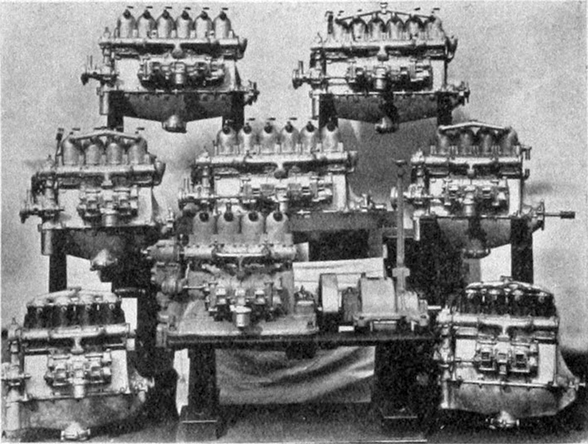
N.E.C. produced three water-cooled vertical engines during 1910, all with 77 mm (3.032") bore and 108 mm (4.252") stroke cylinders. The twin displaced 1.006 l (61.38 in³) and was rated 20 hp at 1,250 rpm. The four displaced 2.012 l (122.76 in³) and developed 40 hp at 1,250 rpm. The six displaced 3.017 l (184.14 in³) and produced 60 hp at 1,250 rpm.
A water-cooled vertical four with a 84.5 mm ( 3.327") bore, 108 mm (4.252") stroke, 2.423 l (147.84 in³) displacement and weighing 70.3 kg (155 lb) was rated 40 hp at 1,500 rpm.
An air-cooled vertical four with a 114 mm (4.488") bore, a 101 mm (3.976") stroke, and 4.124 l (251.64 in³) displacement developed 70 hp at 1,500 rpm and weighed 131.5 kg (290 lb).
A water-cooled vertical six with a 94 mm (3.701") bore, 114 mm (4.488") stroke and 4.747 l (289.67 in³) displacement was rated 90 hp at 1,250 rpm and weighed 145.1 kg (320 lb).
Another water-cooled vertical six, introduced in 1912 with a 101 mm (3.976") bore, 115 mm (4.528") stroke, and 5.528 l (337.35 in³) displacement produced, 100 hp at 1,250 rpm and weighed 131.54 kg (290 lb).
A water-cooled V-4 with a 77 mm (3.032") bore, 108 mm (4.252") stroke and 2.012 l (122.76 in³) displacement was rated 40 hp at 1,250 rpm and weighed 60.3 kg (133 lb).
A water-cooled V-4 with a 94 mm (3.701") bore, 114 mm (4.488") stroke and 3.164 l (193.11 in³) displacement was rated 50 hp at 1,250 rpm and weighed 70.31 kg (155 lb).
A water-cooled V-4 with a 101 mm (3.976") bore, 115 mm (4.528") stroke and 3.685 l (224.87 in³) displacement also was rated 50 hp at 1,250 rpm and weighed 70.31 kg (155 lb).
 |
 |
 |
 |
 |
| 40 hp Inline Four | Inline Fours and Sixes | V-4, Fore and Aft Views | V-4 Cutaway in London Science Museum | |
Novus
 |
| Novus Rotary (AEE) |
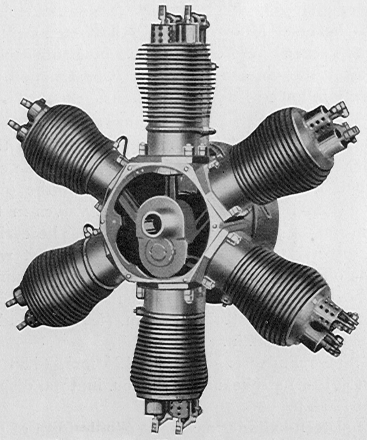
This is a strange one, included here for that reason. The Novus was a six-cylinder air-cooled rotary built by Horch and Company of Zwickau, Germany. With a 120 mm. (4.724") bore, 130 mm. (5.118") stroke and 8.822 l (538.33 in³) displacement, it developed 70 hp at 1,200 rpm and weighed 100 kg (221 lb). It was available either as a conventional rotary with fixed crankshaft and rotating cylinders, or a differential rotary whose cylinders rotated in one direction and its crankshaft in the opposite direction, each driving a propeller at half the speed that would have otherwise been required.
Novus rotaries were constructed entirely of alloy steel and used ball bearings throughout. The mechanically-operated inlet and exhaust valves were actuated via push rods, rocker arms and a special cam that controlled the valves in groups of three. Unfortunately, neither the last sentence nor the one available engine image sheds much light on the clearly uneven Novus firing order. The pistons were lubricated by oil that was led from a ring-shaped oil canal to the skirt surface through tubes that curved opposite to the engine's rotation.
References
Angle, Glenn D, ed. Aerosphere 1939 (New York, New York: Aircraft Publications, 1940).
Anble, Glenn D, ed. Airplane Engine Encyclopedia (Dayton, Ohio: Otterbein Press, 1921).
Image Sources: A39 = Aerosphere 1939; AEE = Airplane Engine Encyclopedia; Flt = Flight Magazine; NARA = U.S. National Archives and Records Administration; UKNA = United Kingdom National Archives.
Send mail to
![]() with questions or comments about this web site.
with questions or comments about this web site.
![]()