Selected Early Engines
Junkers
Compiled by Kimble D. McCutcheon
Published 1 Aug 2022
Junkers
Professor Hugo Junkers (1859 – 1935), a German engineer and aircraft designer, pioneered all-metal cantilevered aircraft construction and diesel aircraft engines. Junkers founded the first of his many companies, Hugo Junkers Civilingenieur, at Dessau, Germany on 21 Oct 1892. The most notable Junkers companies were Junkers Flugzeugwerke AG of Dessau founded in March 1919 for aircraft production and Junkers Motorenbau GmbH of Dessau founded on 27 Nov 1923 for engine production. When in 1933 Professor Junkers refused to assist the Nazis in re-arming Germany, the Nazi regieme seized his patents and placed him under house arrest, where he died. The Nazis took over his companies and combined the aircraft and engine companies to form Junkers Flugzeug- und Motorenwerke AG in Dessau on 05 Jul 1936. This organization produced many notable aircraft and engines for the German WWII effort. It merged with Messerschmitt-Bölkow-Blohm (MBB) in 1966.
|
| WWI Diesel (AEE) |
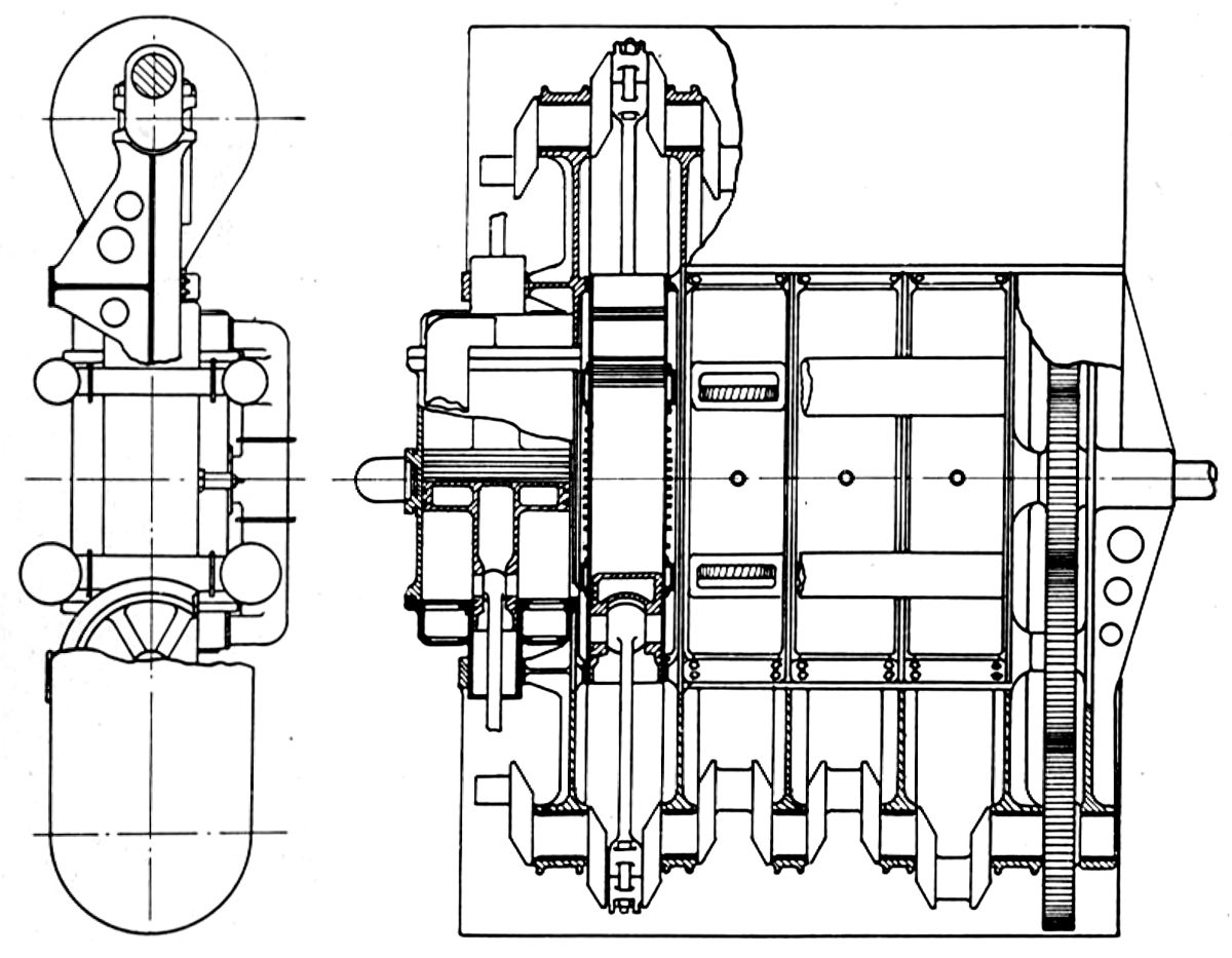
Junkers built experimental two-stroke opposed-piston diesel aircraft engines during WWI, which were derived from a stationary engine line. These featured two crankshafts at the cylinder ends connected by a gear train that also drove the propeller. Two pistons, working in opposite directions in each cylinder, uncovered inlet and exhaust ports near the ends of their strokes. The exhaust port was uncovered first, and when the inlet port was uncovered, a compressed air charge was forced through the cylinders, practically clearing all burnt gases. Junkers found that the excellent scavenging, perfect inertial balance, and absence of restricting valves suggested diesel engines capable of high speed and high mean effective pressures. The cylinder working surfaces were completely surrounded by cooling water and the pistons contained a coolant that transferred heat from the head to the skirt where it was given up to the cylinder walls. A four-cylinder engine developed 200 hp at 1,000 rpm and weighed about 3.5 lb/hp. It was 52" long, 18" wide and 61" high. An experimental six-cylinder was also built.
The L1, an air-cooled vertical six whose design started in 1920, was Junkers first serious aircraft engine. With a 95 mm (3.740") bore, 120 mm (4.724") stroke, 6:1 compression ratio and 5.104 l (311.47 in³) displacement, it produced 75 hp at 1,800 rpm.
The L1a air-cooled vertical six of 1923 with its 100 mm (3.937") bore, 120 mm (4.724") stroke, 5:1 compression ratio and 5.655 l (345.08 in³) displacement produced 84 hp at 1,850 rpm.
Junkers Motorenbau GmbH built its first aircraft engine, the L7 in 1923. The L7 was a water-cooled vertical six evolved from the L1a. With a 105 mm (4.134") bore, 120 mm (4.724") stroke, 6:1 compression ratio and 6.234 l (380.42 in³) displacement, it produced 84 hp at 1,850 rpm. Dry weight without propeller hub was 286 lb. A three-point suspension mounting method was used.
 |
| L2 (A39) |
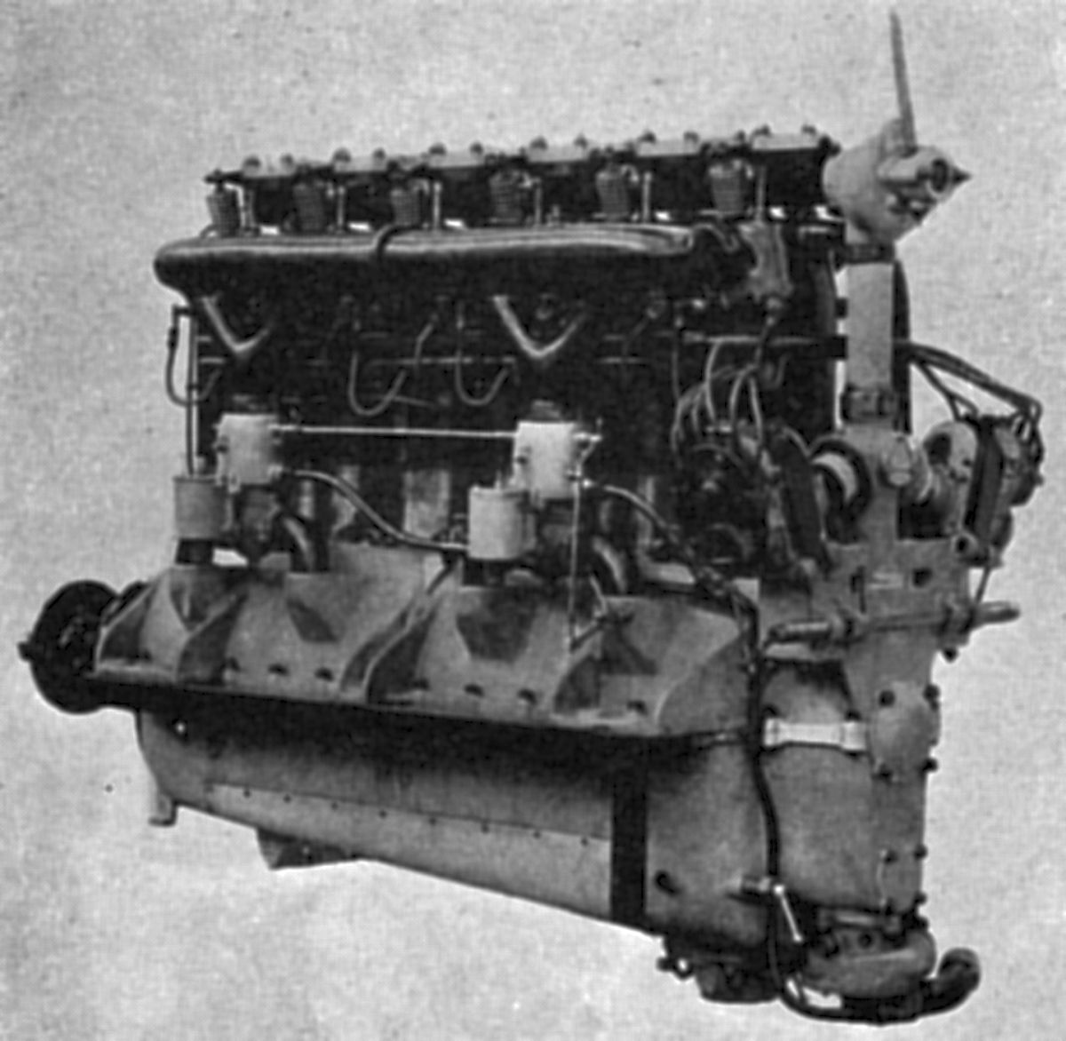
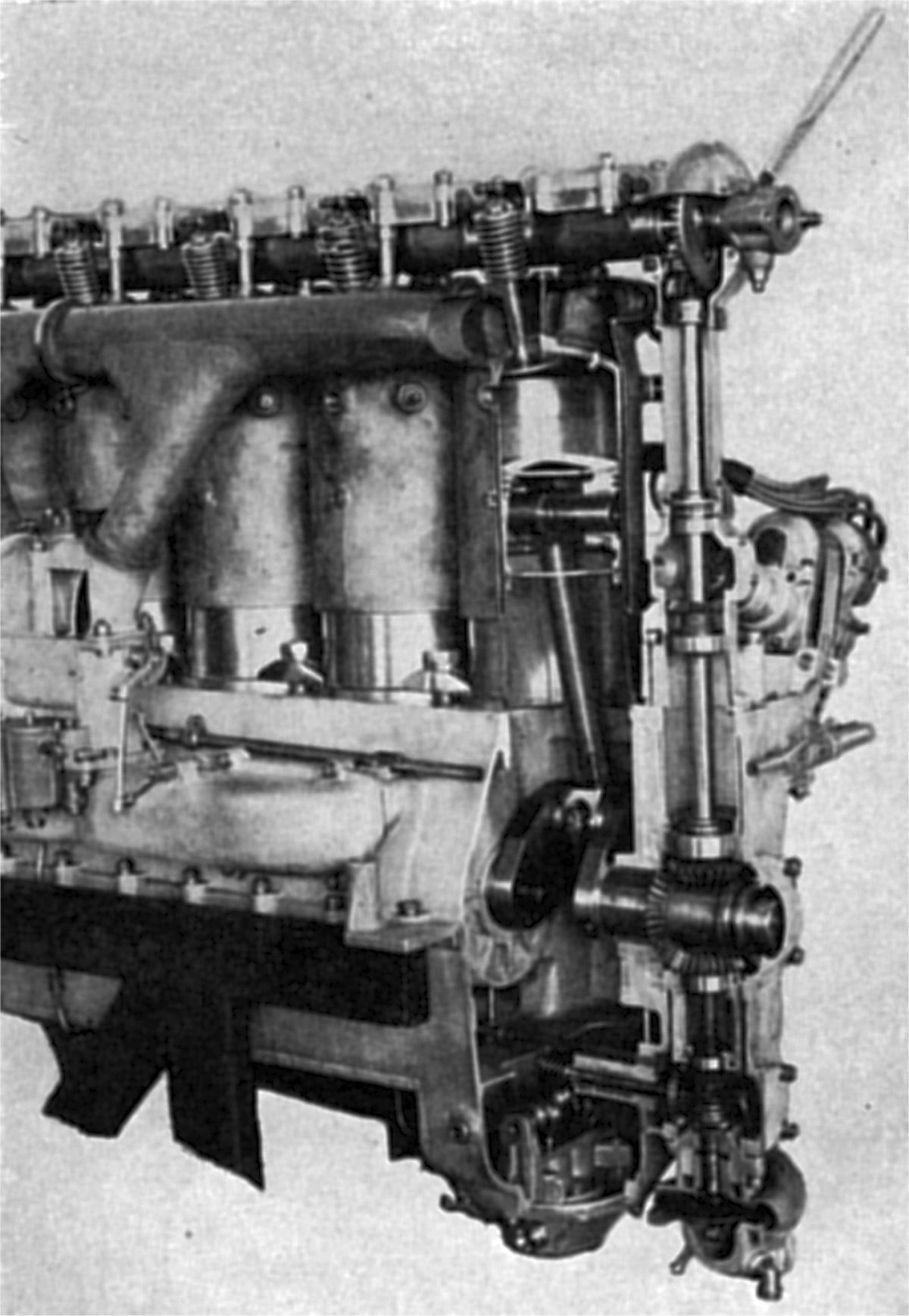
The L2, a water-cooled vertical six, had a 150 mm (5.906") bore, 180 mm (7.087") stroke, 6.03:1 compression ratio and 19.085 l (1,164.64 in³) displacement. It produced 265 hp at 1,450 rpm and weighed 627 lb without the propeller hub. Fuel and oil consumption was 0.506 and 0.024 lb/hp/hr. Individual welded-steel cylinders had inclined valves operated via rocker arms and an overhead camshaft in an aluminum housing bolted to the cylinder heads. The camshafts was driven by vertical shafts and gears at the engine rear. Two rear-mounted Bosch ZH6 magnetos furnished dual ignition; these were mounted inclined and crosswise. Two carburetors drawing inlet air through crankcase passages fed three cylinders each. The fuel was benzol. A dry-sump pressure lubrication system using a plunger pump supplied oil to the bearings. The engine was 60.63" long, 24.6" wide and 45.79" high.
 |
 |
| L5 (A39) | |
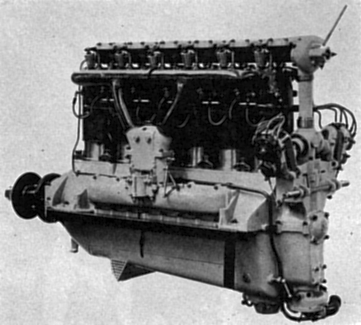
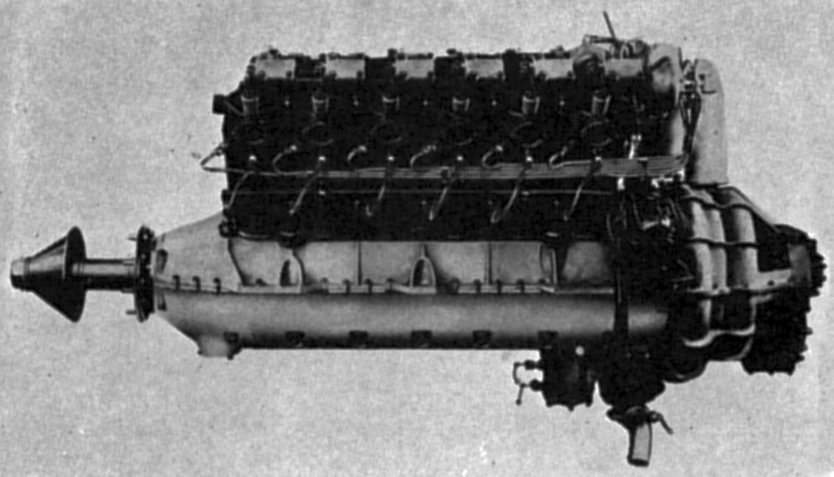
The L5 was based upon experience gained with the L2. It was fitted with a special altitude regulator and fuel economizer that decreased power loss at high altitude and lowered the fuel consumption at low altitudes. The L5 established worlds records for altitude and distance in August 1927. A water-cooled vertical six with a 160 mm (6.299"") bore, 190 mm (7.480") stroke, 5.5:1 compression ratio and 22.921 l (1,398.73 in ³) displacement, it produced 310 hp at 1,450 rpm. When built with a 7:1 compression ratio it delivered 350 hp. Dry weight (minus propeller hub) was 711 lb. Length was 68.95", width 22" and height 49.8". A single duplex carburetor was used and fuel consumption 0.484 lb/hp/hr. Trunk type aluminum alloy pistons were fitted with four rings and full-floating piston pins. The tubular-shank connecting rod big ends had bronze-backed white-metal-lined bearings. The six-throw crankshaft was supported by ball bearings whose inner races were threaded over the cranks and supported on split bushings.
 |
 |
 |
 |
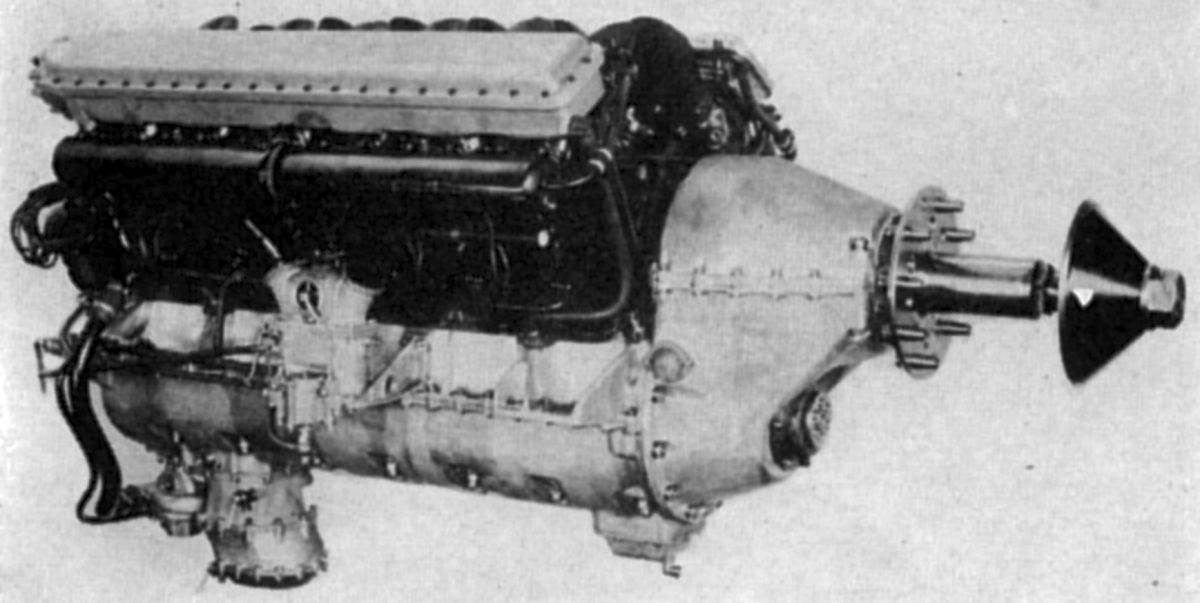
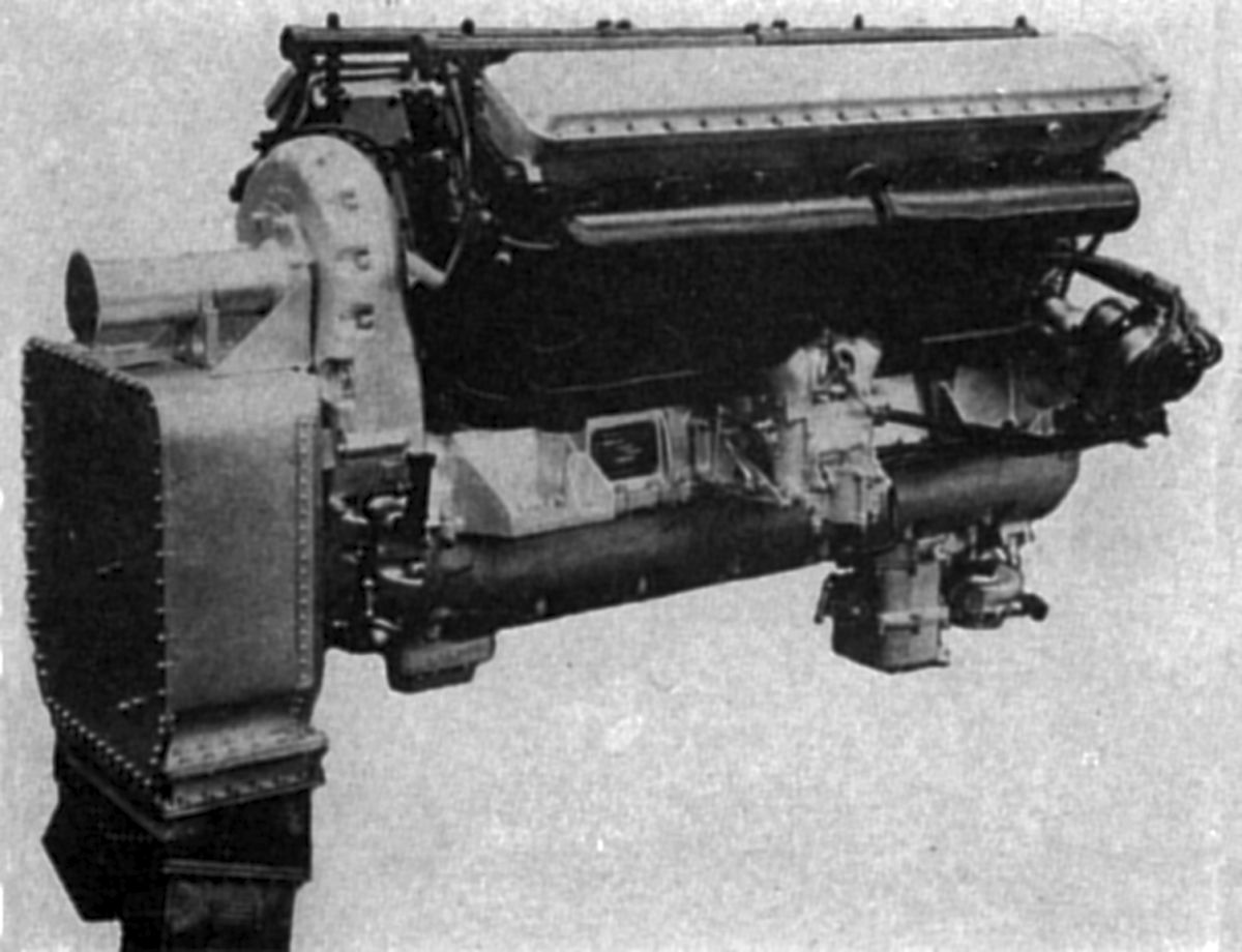
| L55 (A39) | Supercharged L55 (A39) | ||
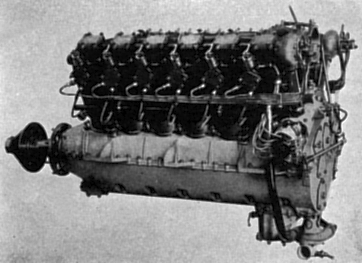
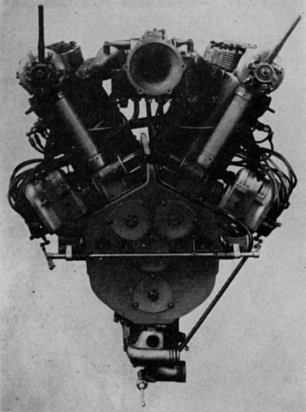
The L55, a 60° V-12 introduced in 1928, employed L5 cylinders. Its displacement was 45.841 l (2797.45 in³), its compression ratio 5:1, and its normal output was 500 hp at 1,380 rpm. With a 5.5:1 compression ratio it produced 600 hp, and with a 7:1 compression ratio 625 hp. Time-limited power at 1,520 rpm was 600 hp with the 5:1 compression ratio, was 650 hp with the 5.5:1 compression ratio and 700 hp with the 7:1 compression ratio. Dry weight, less propeller hub, was 1254 lb. Fuel and oil consumptions were 0.484 – 0.506 lb/hp/hr and 0.033 lb/hp/hr. The L55 was 69.96" long, 33.07" wide and 50.12" high. The articulated connecting rods used split big ends with triangular side flanges for the link rod knuckle pins. Through bolts extending from the crankcase top through nuts at the crankcase bottom captured the main bearing saddles. One magneto was driven from each camshaft drive shaft to provide dual ignition. The inlet manifolds and carburetors were situated in the cylinder Vee. The L55 was also built with gear-driven two-stage centrifugal supercharger outwardly resembling the Rateau design. The supercharger was driven through a hydraulic coupling that served as a damping device as well as a speed control that could range between six and seven times crankshaft speed. The centrifugal supercharger only delivered air because the carburetor was interposed between the blower and inlet manifolds. The supercharged L55 normal rating was 500 hp at 1,380 rpm, and the time-limited power with full supercharge was 700 hp. Dry weight, propeller hub, was 1421 lb. The engine's length was 87.28", its width 33.07" and its height 50.12".
The L8 was a water-cooled vertical six with 2:1 propeller reduction gearing. Its 160 mm (6.299"") bore, 190 mm (7.480") stroke, 5.5:1 compression ratio and 22.921 l (1,398.73 in ³) displacement were the same as the L5 model, but it featured four valves per cylinder. Normal output was 350 hp at 1,880 rpm and maximum output was 420 hp at 2,000 rpm. Fuel consumption was 0.484 lb/hp/hr, dry weight was 902 lb, length was 69", width 22" and height 45". The steel cylinders, with integral barrel and head, had separate sheet steel water jackets welded in place. A single valve gear housing containing two camshafts acting directly upon the valves, was attached to the cylinder heads. A friction damper between the crankshaft and propeller shaft absorbed crankshaft torque fluctuations. A slide valve for a gas starter was fitted to each cylinder and operated from the camshafts.
The L8a was fitted with an extension shaft for driving the propeller.
 |
 |
| L88a (A39) | (A39) |
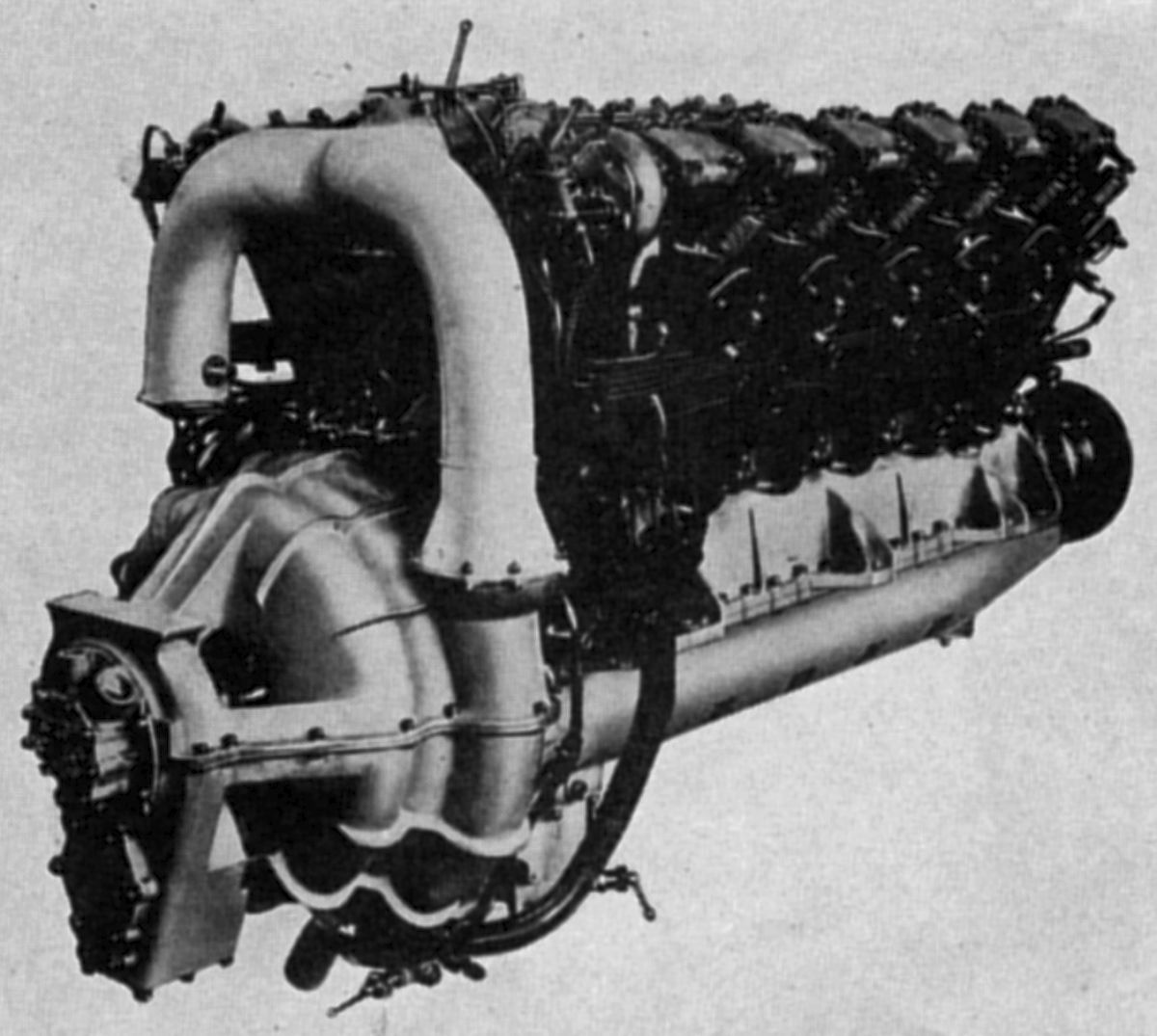
The L88a, a double L8 version, was a 60° V-12 with propeller reduction gears, had a 650 hp at 1,675 rpm normal rating and an 800 hp at 1,850 rpm. Dry weight was 1650 lb, length was 71", width was 33" and height was 49".
The L88b was a later L88a version ignition and valve gear drives at the engine front, which reduced crankshaft torsional vibration effects, as well as engine length. The bore, stroke, compression ratio and displacement remained the same as the L88a. The four valves in each cylinder were operated through intermediate levers from two camshafts carried in a housing bolted to the cylinder heads. The inclined camshaft drive shafts were housed in expanding tubes. The cast Elektron crankcase was deeper to provide greater rigidity and to allow the cylinders to extended farther into the crankcase. The upper crankcase, in conjunction with main bearing caps, supported the crankshaft's eight main journals, which meant that the lower crankcase was just a removable oil sump. The spur-type propeller reduction gears had a 2.18:1 ratio. Articulated connecting rods had H-section shanks. A double carburetor was located outside each cylinder bank instead of in the Vee. Normal output was 700 hp at 1,850 rpm and maximum was 850 hp at 2,100 rpm. Weight was 1540 lb, length was 64", width was 37.5", and height was 47".
The L5G, a refined L5 model, retained the 160 mm (6.299"") bore, 190 mm (7.480") stroke, 5.5:1 compression ratio and 22.921 l (1,398.73 in ³) displacement. It was rated 340 hp at 1,700 rpm on 80 octane fuel. Fuel and oil consumptions were 0.52 and 0.022 lb/hp/hr. Dry weight was 754 lb, or 2.21 lb/hp. Length was 70.87", width was 25.59" and height was 47.83".
Junkers continued active engine line development through the 1930s and 1940s. The Jumo 204, patterned after the WWI experimental diesels and first in the line of successful aircraft diesels, was introduced in 1932; it led to the highly successful Jumo 205. The Jumo 210, a gasoline-powered liquid-cooled inverted V-12, was introduced in 1937 and was subsequently developed into several WWII-era engines. Junkers also produced an early turbojet, the Jumo 004.
References
Angle, Glenn D, ed. Aerosphere 1939 (New York, New York: Aircraft Publications, 1940).
Anble, Glenn D, ed. Airplane Engine Encyclopedia (Dayton, Ohio: Otterbein Press, 1921).
The Hugo Junkers Homepage
Image Sources: A39 = Aerosphere 1939; AEE = Airplane Engine Encyclopedia; Flt = Flight Magazine; NARA = U.S. National Archives and Records Administration; UKNA = United Kingdom National Archives.
Send mail to
![]() with questions or comments about this web site.
with questions or comments about this web site.
![]()