Selected Early Engines
Indian, Irwin, Isaacson, Issoto-Fraschini
Compiled by Kimble D. McCutcheon
Published 12 Ju1 2022; Revised 01 May 2026
Indian
The Hendee Manufacturing Company of Springfield, Massachusetts, well-known for its Indian motorcycles, also built airplane engines.
|
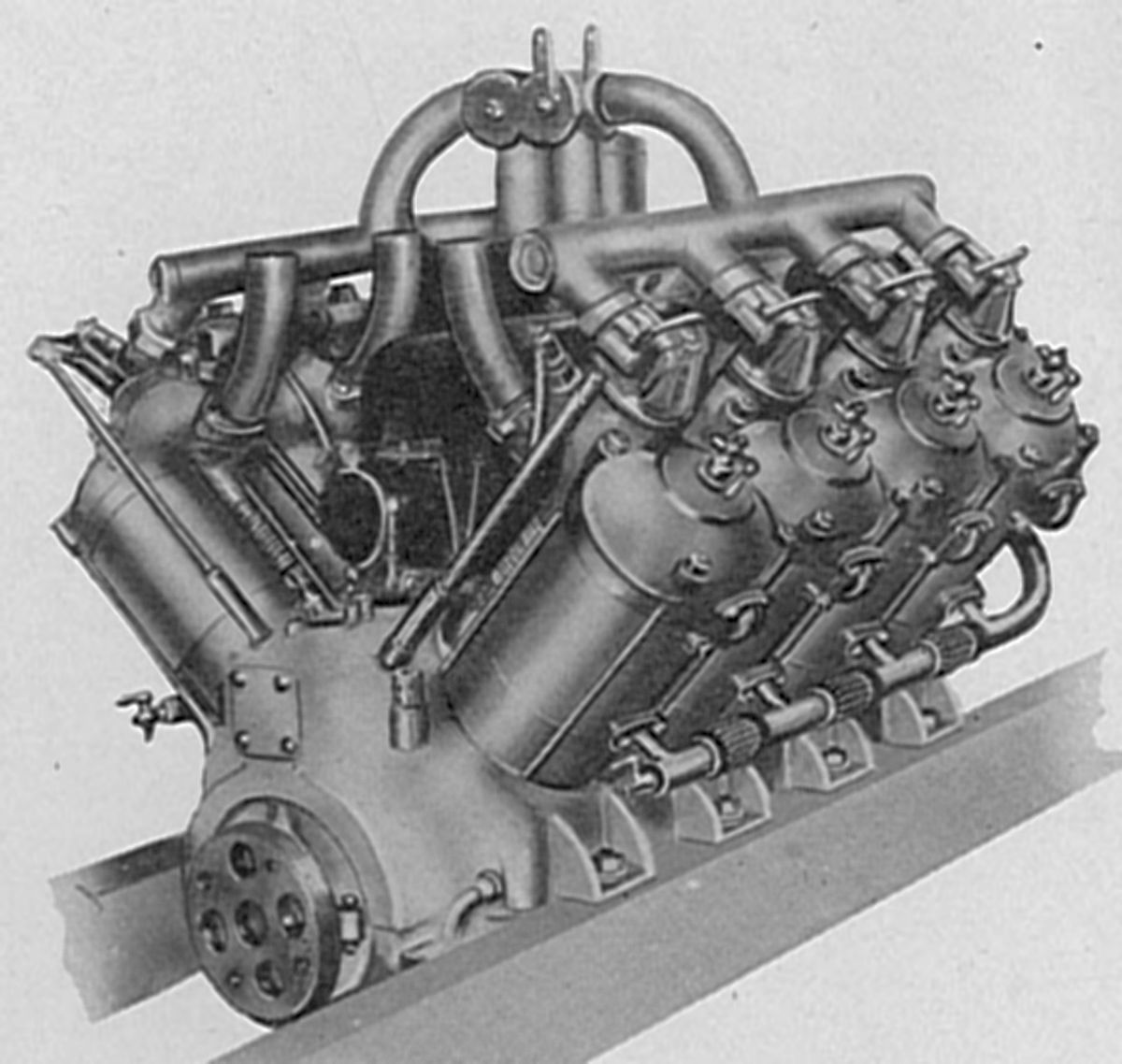
| Indian V-8 (AEE) |
Glenn Curtiss used a water-cooled Indian V-8 in distance flights during the 1910 Harvard Aviation Meet. It had a 4.000" (101.6 mm) bore, 4.500" (114.3 mm) stroke and 452.39 in³ (7.413 l) displacement. Rated 60 – 65 hp, it was equipped with magneto ignition and weighed 260 lb. The separate cylinders had separate L-shaped heads and brass water jackets. An inlet valve was located in a removable cage directly above the exhaust valve that facilitated exhaust valve service. The inlet valve was operated by a push rod and rocker arm while the exhaust valve was operated directly from the cam shaft through tappets.
 |
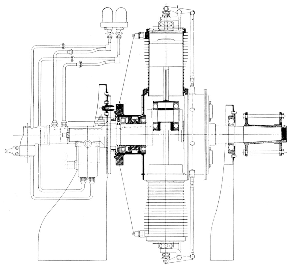 |
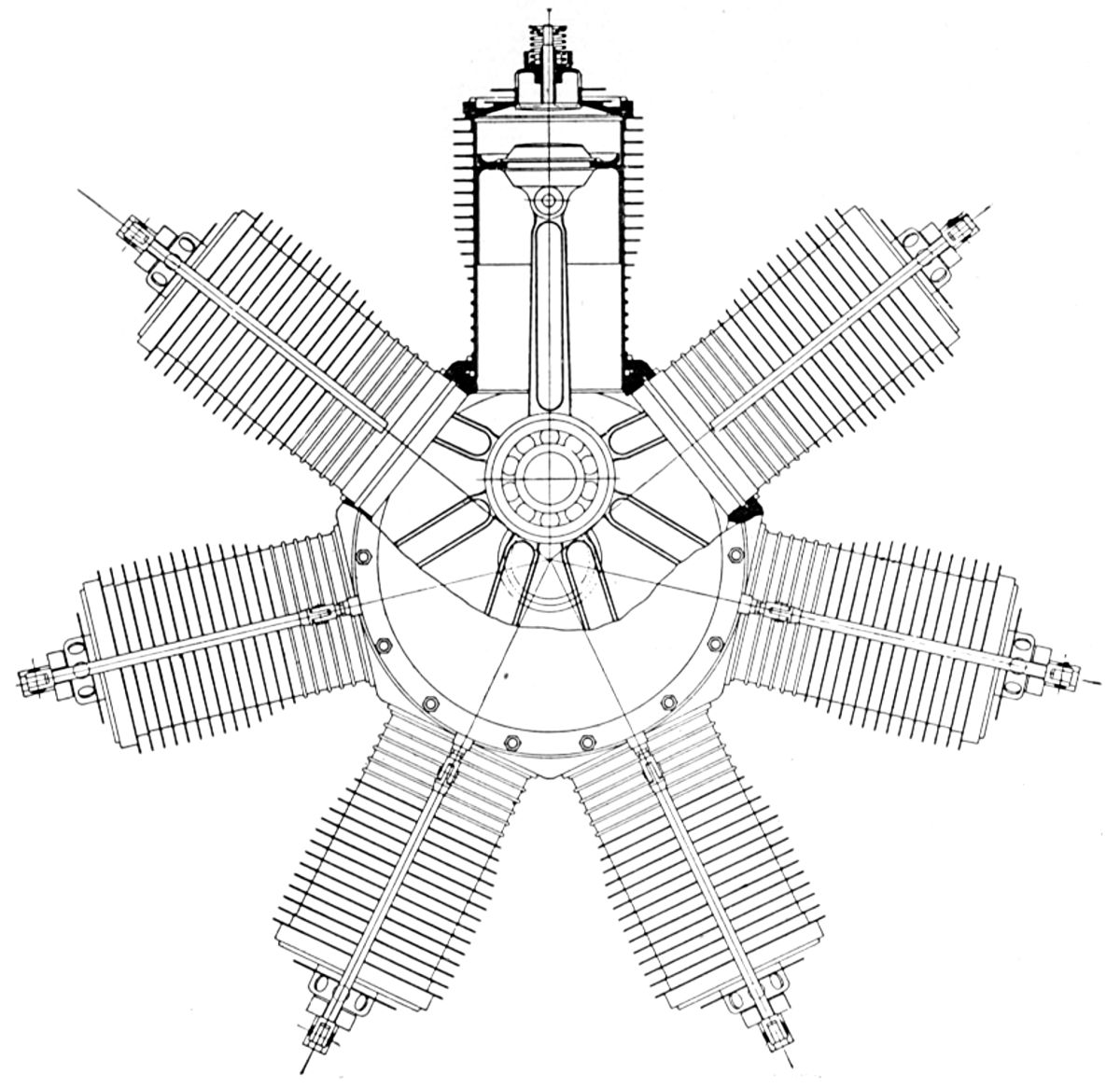
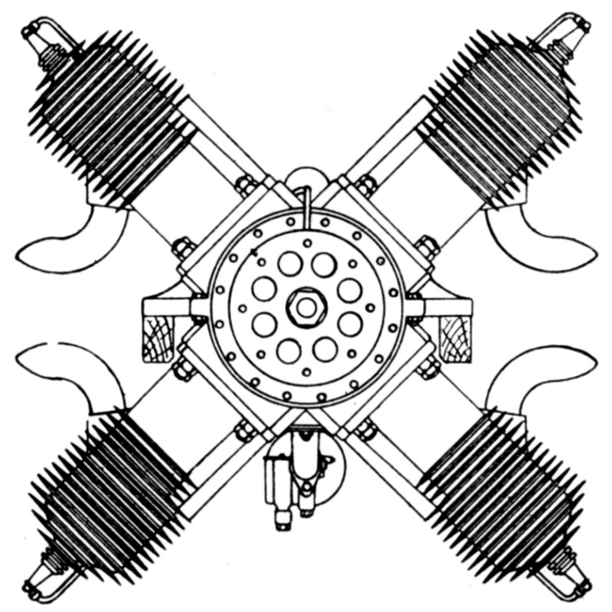
| Indian 7-Cylinder Rotary (AEE) | |
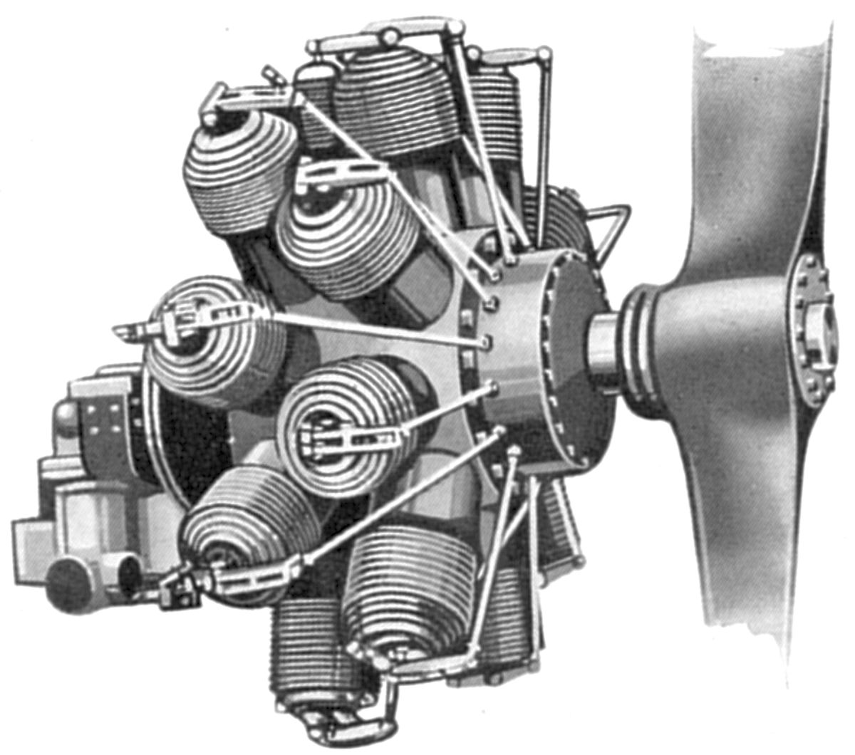
An Indian air-cooled seven-cylinder rotary with a 4.375" (111.13 mm) bore, 4.875" (123.83 mm) stroke and 515.0 in³ (8.407 l) displacement was rated 50 hp at 1,100 rpm and weighed 185 lb., or 3.7 lb/hp. Its diameter was 36". Constructed largely of nickel steel, ball bearings were used throughout. Magneto ignition was used and pumps forced the lubricating oil through sight-feed oilers before going to the main bearings. Automatic inlet valves were located in the piston heads while mechanically-operated exhaust valves used very light springs and centrifugal force to keep them seated. The cylinder head could be removed by unscrewing a castellated ring.
Some air-cooled V-twin Indian motorcycle engines displacing 71 in³ (1.163 l) and developing 18 – 24 hp were used by light-plane builders.
Irwin
 |
| Model 72 (A39) |
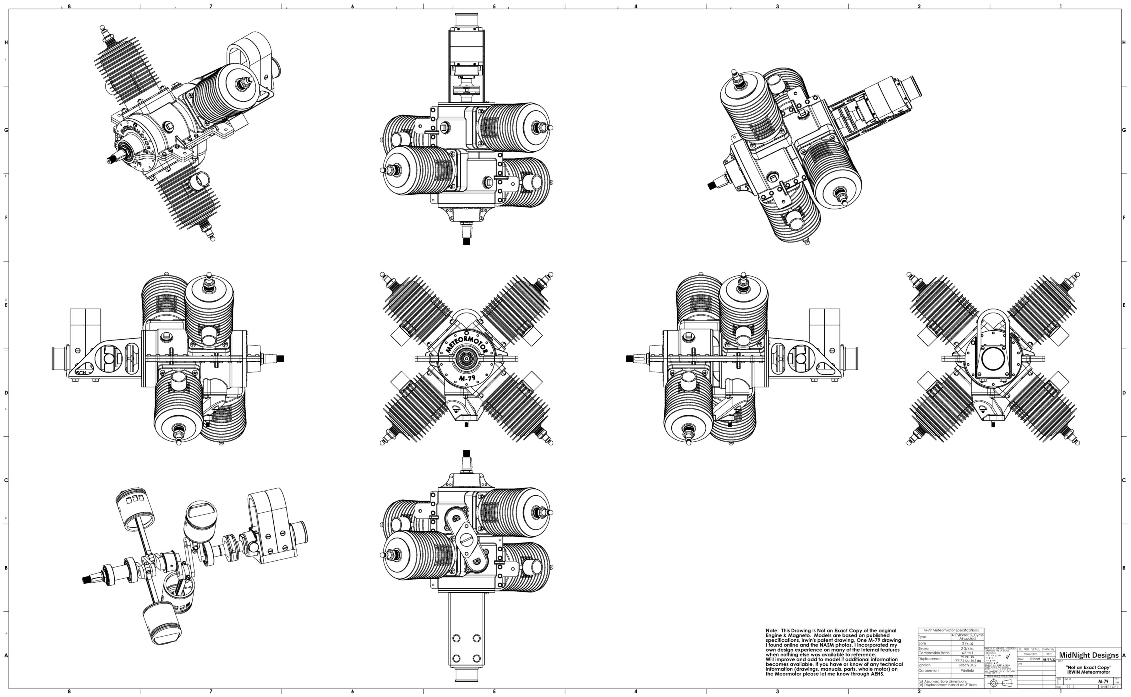
John Fulton (Jack) Irwin, an early balloon and aircraft builder, adventurer, and WWI USASC flight instructor, founded the Irwin Aircraft Company 1919 to market a small biplane he had designed, the M-T Meteorplane. Based in Sacramento, then Watsonville, California, the Irwin Aircraft Company sold M-T plans and kits. Improved versions followed, the M-T-1 in 1922 and the M-T-2 in 1926. Irwin thought he could design a better engine than the converted motorcycle engines that powered the M-T and M-T-1. He introduced the Model 72 Meteormotor in 1925.
This Model 72 was an air-cooled two-stroke four-cylinder radial with a 2.875" (73.03 mm) bore, 2.75" (69.85 mm) stroke and 71.410 in³ (1.171 l) displacement rated 20 hp at 2,000 rpm. Dry weight was 60 lb. The gray-iron cylinders were machined inside and out. Early cylinders used iron cooling fins, but later copper cooling fins were attached to the cylinders by a special electric welding process. The two-throw heat-treated crankshaft was machined from a single 90-lb chrome-vanadium steel forging that weighed just 6.5 lb when complete. It ran on ball hearings. Tubular-shank connecting rods were fitted with steel-backed white-metal-lined bearings. Three rings were fitted to each cast-iron piston. A Zenith carburetor supplied the fuel/air mixture to a branched induction manifold that fed the two crankcase chambers. Tungsten-steel valves with bronze stems housed in the induction manifold crankcase flanges checked the induction mixture flow as it entered the crankcases. The valve stem housings can be seen in the NASM photographs. A single Bosch magneto the ignition. The pressure-fed lubrication system was regulated from the pilot's cockpit.
The Model 79, introduced in 1926, had a 5:1 compression ratio and was rated 20 hp at 1,730 rpm. Fuel and oil consumptions were 0.60 and 0.06 lb/hp/hr. Dry weight, minus starter and propeller hub, was 58 lb. The diameter was 23" and the length 21". Steel cylinder liners had aluminum-alloy castings that were shrunk and doweled into place. The two-throw crankshaft was machined from a single chrome-nickel steel forging and supported on ball bearings. The two-piece aluminum alloy crankcase was split along its horizontal plane and provided with four mounting brackets. The H-section-shank alloy-steel connecting rods had big ends fitted with white-metal-lined bronze bushings. The cast aluminum-alloy pistons were fitted with three rings and attached to the connecting rods with full-floating hollow nickel-steel piston pins. A single Bosch magneto fired a single Bosch spark plug centrally located in each cylinder head. A Winfield carburetor supplied the mixture.
There is ambiguity about the Model 79’s displacement. In 1926, the U.S. Congress made it illegal to sell non-certified aircraft, a law that became effective in 1927. Although this law ended Irwin Aircraft’s kit sales, it did allow for amateur-built aircraft and it appears Irwin continued to sell the Model 79 to homebuilders. Irwin also continued to race his personal aircraft in an NAA/FAI class that required engine displacement to be less than 80 in³. John Riend located a Model 79 dataplate that states the displacement was 79 in³. Despite Glenn Angle’s Aerosphere 1939 assertion that the Model 79 displaced 84 in³ and had a 3.125" (79.38 mm) bore, it is probable that its bore was actually 3.000" (76.20 mm), its stroke was 2.75" (69.85 mm), the same as Model 72, and its displacement was 77.754 in³ (1.274 l).
 |
| M-79 (John Riend) |
The 1934 Model 79 with a 4.8:1 compression ratio was rated 25 hp at 2,150 rpm. The crankcase inlet valve seats were shrunk-in cast iron. Fuel and oil consumptions were less than 0.50 and 0.06 lb/hp/hr. Dry weight was 58 lb, diameter was 24" and length was 18". The exhaust port opened at 112° after top center and closed at 112° before top center, for a 136° exhaust event duration. The inlet transfer port opened at 63° after top center and closed at 62° before top center, for a 125° inlet event duration.
Between 75 and 80 Model 79s were built.
Acknowledgement
John Riend, who is working on an Irwin Engine CAD model, contributed to this research and to understanding the engine details. We are actively seeking additional information on these engines. If you know something that does not appear in this short article, please contact the webmster (below).
U.S. Patent NASM Images Drawing CAD Rendering Brochure
Isaacson
 |
| Rotary-18 (AEE) |
Isaacson engines were early British-built air-cooled rotaries and radials.
The two rotaries had 120 mm (4.724") bores, 150 mm (5.906") strokes, inlet valves located in the pistons and exhaust valves in the cylinder heads.
The nine-cylinder rotary, which displaced 15.268 l (1.696 l (931.71 in³), was rated 100 hp at 1,200 rpm, and weighed 250 lb, or 2.5 lb/hp.
The eighteen-cylinder rotary, which displaced 30.536 l (1,863.42 in³), was rated 200 hp at 1,200 rpm, and 465 lb, or 2.33 lb/hp.
A seven-cylinder fixed radial with a 90 mm (3.543") bore 115 mm (4.528") stroke and 5.121 l (312.50 in³) displacement, was rated 50 hp at 1,600 rpm The propeller ran at one-half crankshaft speed. The crankshaft was mounted on ball bearings, and the pistons were made of steel. Bosch magnetos supplied the ignition. Weight was 195 lb, or 3.9 lb/hp.
A fourteen-cylinder fixed radial displacing 10.242 l (625.01 in³) produced 100 hp at 1,600 rpm and weighed 299 lb, or 2.9 lb/hp.
Another seven-cylinder fixed radial with a 110 mm (4.3321") bore, 130 mm (5.118") stroke and 8.648 l (527.73 in³) displacement was rated 65 hp at 1,100 rpm. This engine employed an inlet valve in the piston and an exhaust valve in the cylinder head, similar to the air-cooled rotaries. Weight was 196 lb, or 3 lb/hp.
Issoto-Fraschini
Cesare Isotta and Vincenzo Fraschini founded Società Milanese Automobili Isotta, Fraschini & C. in 1900. Issoto-Fraschini introduced the M-1, its first aircraft engine, in 1908.
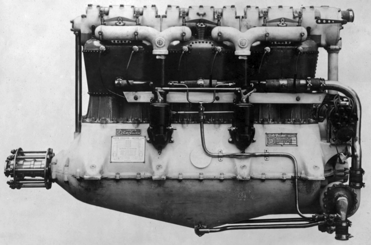
The M-1, a water-cooled V-8 with a 92 mm (3.622") bore, 100 mm (3.937") stroke, 5.318 l (324.52 in³ ) displacement and 2:1 propeller reduction ratio, developed 60 hp at 1,800 rpm. Weighing 302 lb, including a 66-lb flywheel, it was used successfully in Voisin training airplanes. The cylinders were cast in pairs and fitted with steel water jackets. The valves were placed on the cylinder sides with the inlet above the exhaust. Pistons and fork-and-blade connecting rods were forged steel. Cooling water was circulated by a gear pump. Forced lubrication was by means of air passed through the oil. An Isotta-Fraschini twin carburetor situated in the Vee supplied the mixture, and an Eisemann magneto furnished ignition.
The V-1, built in 1911 for Enrico Forlanini's F.2 Citta di Milano airship, was credited with being the first Italian aircraft engine to run successfully under full load for 24 consecutive hours. It was a water-cooled vertical four with a 130 mm (5.118") bore, 180 mm (7.087") stroke and 9.557 l (583.19 in³) displacement that developed 90 hp at 1,200 rpm. Weight, including flywheel and water, was 682 lb. The four cylinders were a single iron casting with each cylinder having two inlet and two exhaust valves overhead. Pressure lubrication was via a gear type pump and oil cooler. Dual ignition was supplied, and the carburetor worked at high altitudes.
The V-2, built in 1912 for Enrico Forlanini's F.3 Citta di Milano II airship, was a water-cooled vertical four with a 126 mm (4.961") bore, 180 mm (7.087") stroke and 8.978 l (547.87 in³) displacement that developed 82 hp at 1,000 rpm, 98 hp at 1,200 rpm, and 105 hp at 1,400 rpm. It weighed 374 lb. Iron cylinders were cast in pairs and fitted with overhead valves. Forced lubrication was by means of air passed through the oil. Double jet carburetors were used, and two independent magnetos provided dual ignition.
The V-3, another water-cooled vertical four built for airship use, introduced a spring-supported rocker lever actuating each cylinder pair's valve tips. The rocker arms operated from the cams that were outside the valve gear housing in contrast to the fully enclosed V-1 and V-2 valve gear.
 |
| V-4-B (NARA) |
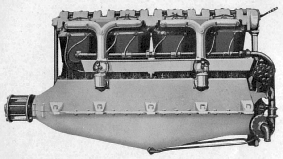
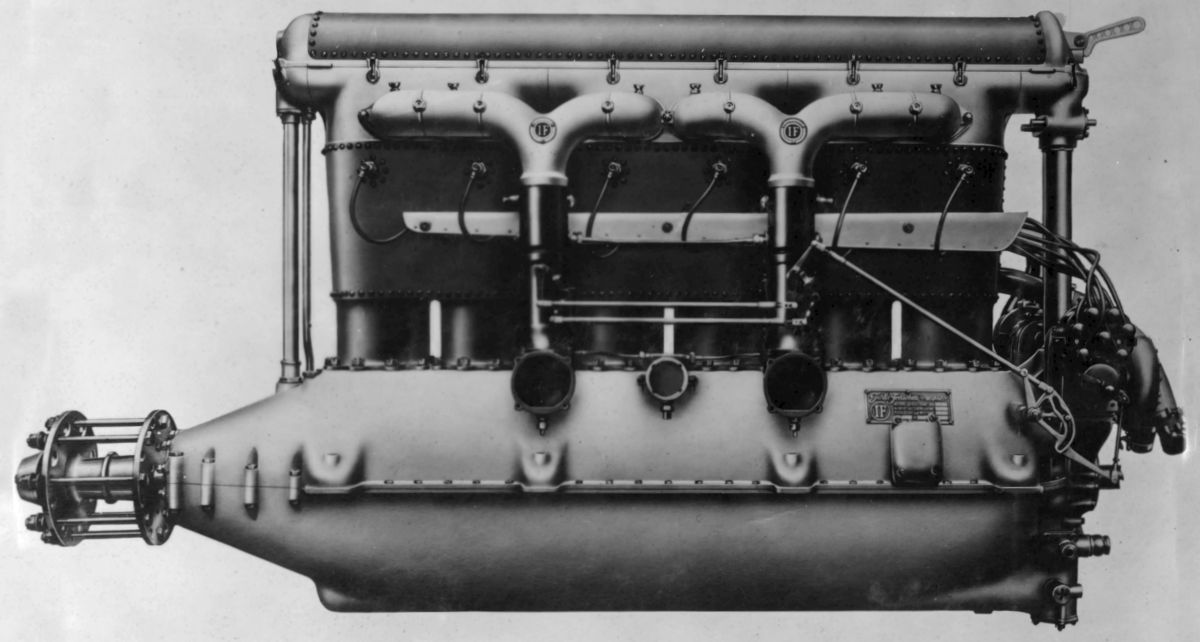
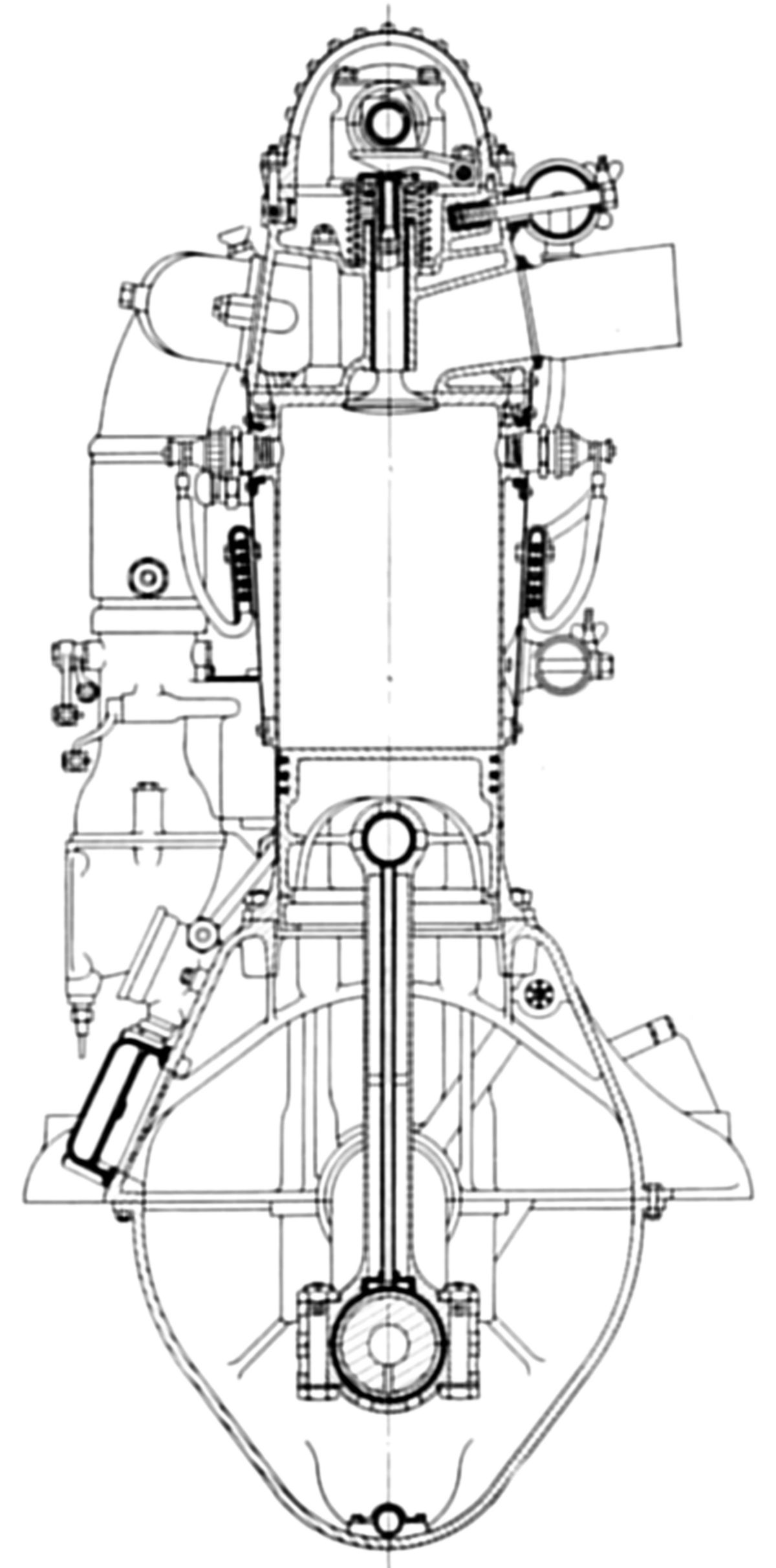
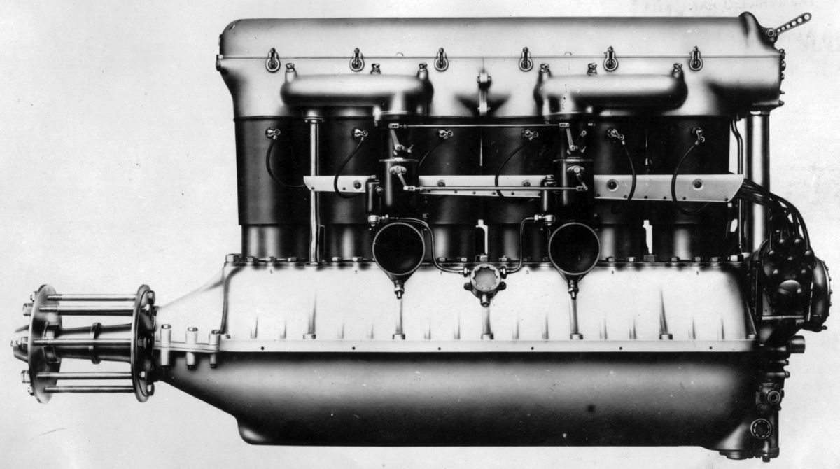
The V-4, derived from the V-3 and introduced in 1914, was a water-cooled vertical six rated 170 hp at 1,450 rpm. With a 130 mm (5.118") bore, the 180 mm (7.087") stroke, 14.335 l (874.78 in³) displacement and 5:1 compression ratio, this direct-drive engine weighed 605 lb, or 3.56 lb/hp. Two Zenith carburetors with 36 mm throats, 1.55 mm main jets and 1.4 – 1.5 mm compensator jets supplied the mixture. A gear pump provided pressure lubrication. Fuel and oil consumptions were 0.485 lb/hp/hr and 0.033 lb/hp/hr. The paired cast-iron cylinders had either steel or copper water jackets. The overhead camshaft featured a compression release mechanism. The inlet valve seated in a cage and the exhaust in the cylinder head. Each valve pair shared a single spring with a pivoted rocker arm, as in the V-3 design. The six-throw four-main-bearing crankshaft was supported by separate bearing caps, each having four bolts. The tubular-shank connecting rods employed two-bolt caps. The aluminum pistons were ribbed underneath their heads. Two six-cylinder Dixie (later Marelli) magnetos furnished dual ignition.
The V-4-A was a V-4 with crankcase volume reduced.
The V-4-B, introduced in 1915, involved further lubricating system modifications. Another gear set was added to scavenge oil from the lower crankcase and deliver it to an external tank. This engine was extensively used, and the Eduardo Bianchi Co. manufactured it under license to meet the demand.
 |
| V-5 (AEE) |
The V-5 was a water-cooled vertical eight introduced in 1915, which used V-4-B cylinders and displaced 19.113 l (1,166.35 in³). It was rated 1,000 hp at 1,400 rpm. The eight-throw crankshaft was supported by five plain main bearings. Two carburetors furnished the mixture, and a force-feed lubrication system was employed. Two eight-cylinder magnetos provided dual ignition. Weight was 825 lb, or 4.12 lb/hp.
The V-5 was also been built with a 190 mm (7.480") stroke, raising the displacement to 20.175 l (1231.15 in³). This version delivered 264 hp at 1,400 rpm, 283 hp at 1,500 rpm, and 290 hp at 1,600 rpm. Issoto-Fraschini built many V-5s and also licensed other Italian firms to build them.
 |
 |
 |
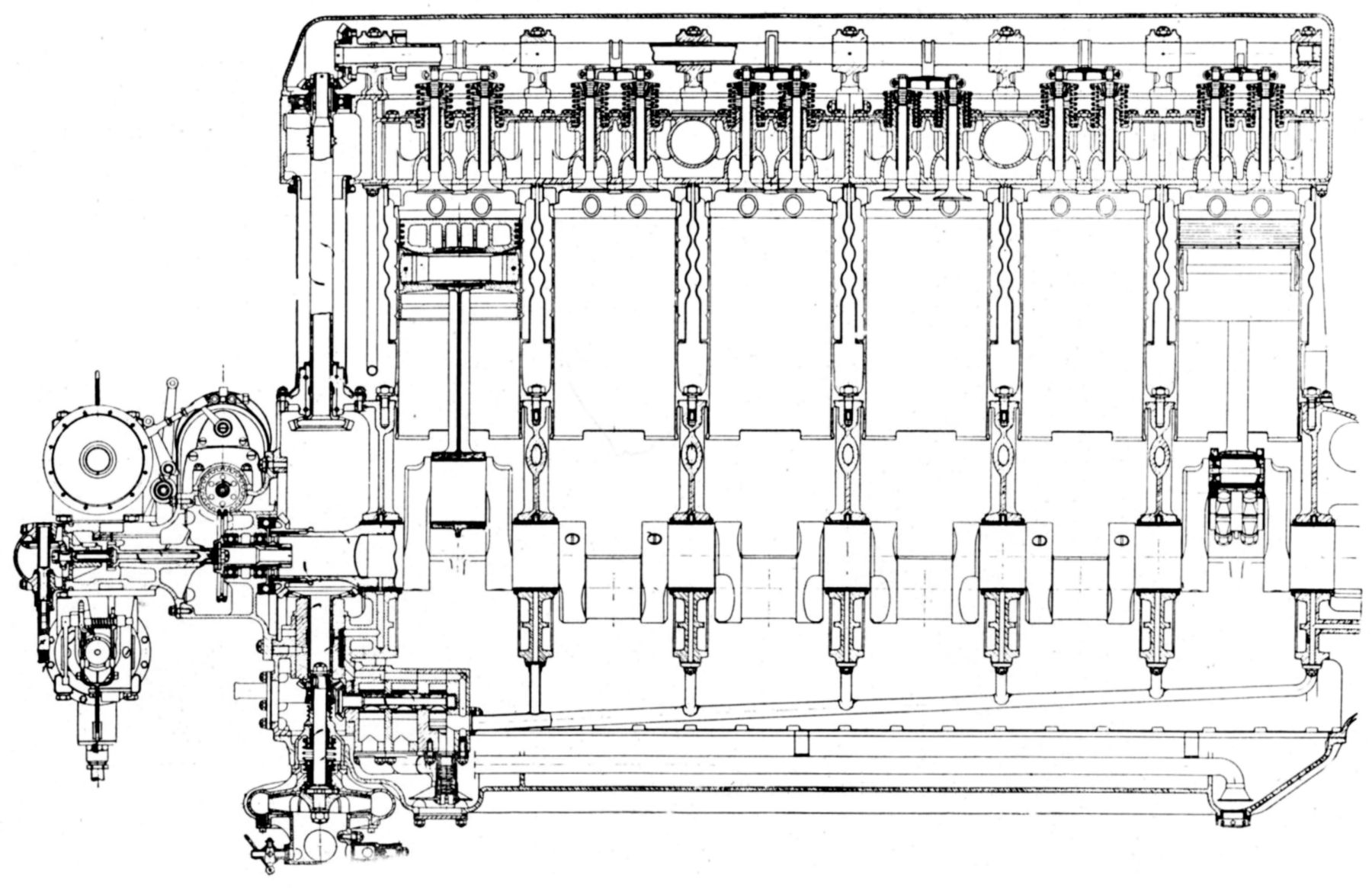
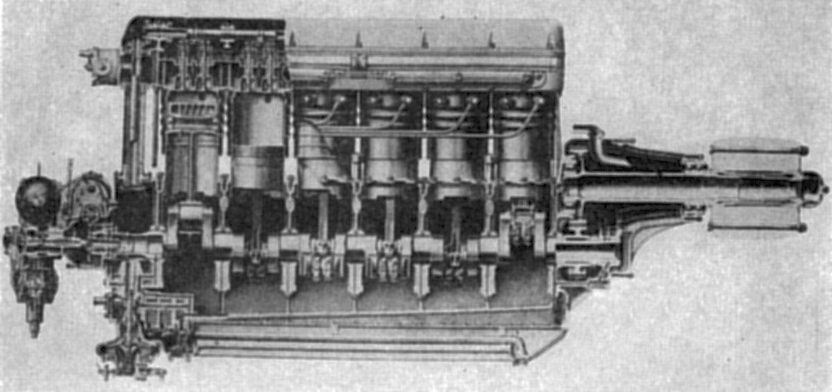
| V-6 (NARA, AEE) | ||
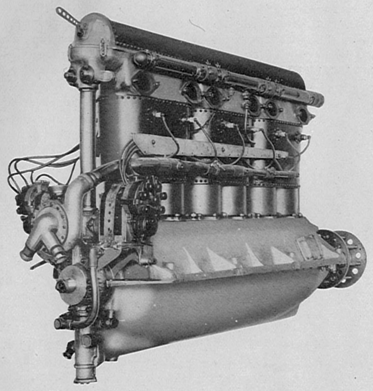
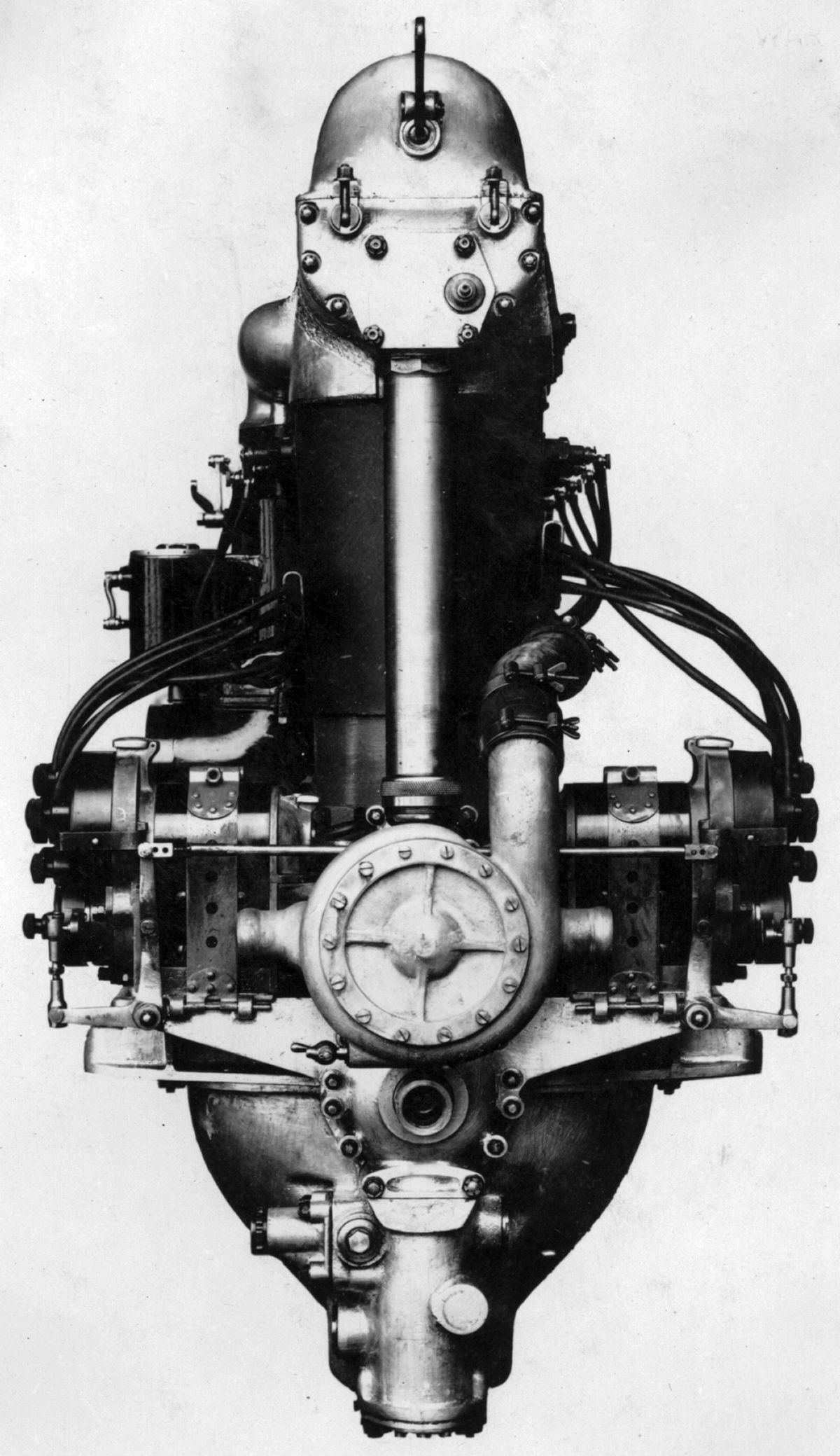
The V-6, a water-cooled vertical six introduced in 1917, had a 140 mm (5.512") bore, 180 mm (7.087") stroke, 16.625 l (1,014.52 in³ ) displacement and 5.1:1 compression ratio. It was rated 250 hp at 1,650 rpm and developed 275 hp at 1,800 rpm. Fuel consumption was 0.485 – 0.503 lb/hp/hr. Two Zenith carburetors fed three cylinders each. A triple vane pump that turned at 1.25 times engine provided dry-sump lubrication with the upper unit supplying the bearings, and the two lower units scavenging. An overflow oil pipe at the propeller end drained camshaft housing oil. The steel cylinders were machined separately and then arranged in pairs. A bolted-on aluminum casting containing the inlet and exhaust valve ports formed the head for each cylinder pair. Steel water jackets were secured by numerous small screws. Two 60-mm (2.362") vertical valves with 30° seats were operated by an enclosed overhead camshaft mounted in seven plain bearings. The camshaft acted upon interposing levers instead of directly upon the valves. Valve clearance adjustment was similar to Hispano-Suiza designs. Inlet valve lift was 0.433" and the exhaust valve lift was 0.492". Inlet valves opened 8° late and closed 48° late; exhaust valves opened 40° early and closed 14° late. The four-main-bearing crankshaft employed either H- or tubular-section connecting rods. The aluminum alloy pistons, ribbed on the interior, were fitted with three compression rings and one oil scraper. Two Marelli EM-6 magnetos furnished dual ignition. Dry weight was 620 lb, or 2.48 lb/hp. The V-6 was 68" long, 20" wide and 39.5" high. Eduardo Bianchi Co., San Giorgio of Sestri Ponente, and Romeo of Milan were licensed to build the V-6, which powered the Macchi 7 and the Savoia 13 airplanes successfully in the 1919 and 1921 Schneider Cup Races.
 |
| V-7 (NARA) |
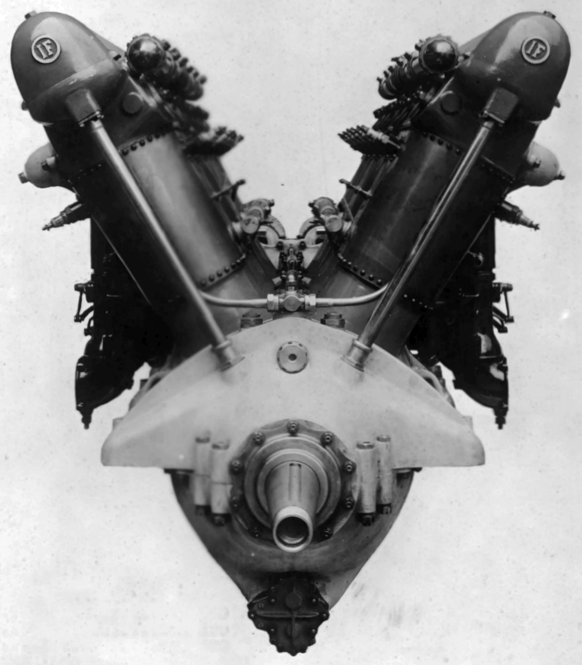
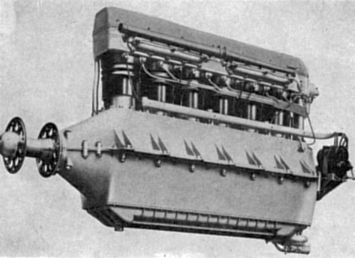
The V-7, a water-cooled 60° V-12 introduced in 1917 used V-6 cylinders with 140 mm (5.512") bores and 180 mm (7.087") strokes for a 33.251 l (1,846.03 in³ ) displacement that was rated 400 hp, developed 460 hp at 1,500 rpm, and 510 hp at 1,700 rpm. Dry weight was 1,070 lb, or 2.67 lb/hp. A V-6 style lubricating system was used. Four Zenith carburetors feeding three cylinders each furnished the mixture, and four magnetos furnished dual ignition. Fuel and oil consumptions were 0.485 and 0.033 lb/hp/hr.
The V-8, derived from the V-6, was a water-cooled vertical six built in 1918 with a 150 mm (5.906") bore, 170 mm (6.693") stroke and 18.205 l (1,110.94 in³) displacement rated 300 hp at 1,800 rpm, and weighing 595 lb, or 1.98 lb/hp. It used a six-throw seven-main-bearing crankshaft. Separate steel cylinders were fitted with sheet iron water jackets that were welded and screwed in place. Tubular-shank connecting rods were used.
 |
 |
| V-9 (NARA) | |
The V-9 was a water-cooled vertical six derived from the V-6 model, but more sturdily built. Introduced in 1918, few were built before WWI ended. With a 150 mm (5.906") bore, 180 mm (7.867") stroke and 19.856 l (1,211.50 in³) displacement, it weighed 684 lb (2.28 lb/hp), was rated 300 hp at 1,700 rpm and 314 hp, at 1,800 rpm.
The V-10, introduced in 1923, was a water-cooled vertical six with a 153 mm (6.024") bore, 180 mm (7.867") stroke and 19.853 l (1211.69 in³) displacement that was rated 340 hp at 1,800 rpm, and 350 hp at 1,850 rpm. Fuel consumption was 0.495 – 0.517 lb/hp/hr. Dry weight with an aluminum crankcase, minus propeller hub, was 726 lb, 675.4 lb with an Elektron crankcase. A supercharger option was available. Steel cylinder barrels were fitted with sheet-steel jackets, and the detachable cylinder head was cast aluminum alloy. The pistons were Elektron and the connecting rods had tubular shanks. The crankshaft was carried in seven bearings that were supported by the upper and lower crankcase sections when the two were bolted together. Pressure dry-sump lubrication was maintained by a triple gear pump. Two Zenith carburetors furnished the mixture after the inlet air was heated while passing through a crankcase duct. Two Bosch magnetos provided dual ignition.
 |
| Asso 200 (AEE) |
The Asso 200, introduced in the late 1920s, was a water-cooled vertical six that followed the same general construction as other Asso models described below. With a 140 mm (5.512") bore, 160 mm (6.299") stroke, 14.778 l (901.81 in³) displacement and 5.7:1 compression ratio, its guaranteed output was 250 hp at 1,800 rpm, but produced 258 hp at 1,800 rpm and 268 hp at 2,000 rpm. Dry weight 616 lb, length was 76.29", width was 21.81" and height was 39.96".
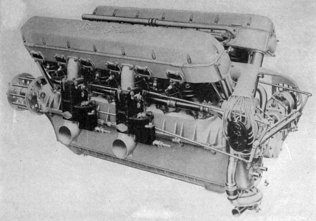
The Asso 500, designed by Giustino Cattaneo and introduced in 1925, was a water-cooled 60° V-12 with a 140 mm (5.512") bore, 150 mm (5.906") stroke, 27.709 l (1690.91 in³) displacement and 5.65:1 compression ratio. It was rated 500 hp at 1,850 rpm but delivered 513 hp at 1,850 rpm. Dry weight was 957 lb, Fuel and oil consumptions were 0.473 – 0.484 and 0.026 – 0.033 lb/hp/hr. Individual cylinders were machined from carbon steel forgings and had welded-on sheet-steel water jackets. A cast aluminum alloy cylinder head for each cylinder bank contained the valve ports, valve guides, and overhead camshafts. Two inlet and two exhaust valves per cylinder were operated by two overhead camshafts, each cam operating a valve pair through an intermediate lever pivoted at he outside. Each aluminum pistons was ribbed underneath its head and had four rings above the piston pin. The six-throw crankshaft rode on eight main bearings, and between the forward bearings a double-row ball bearing carried propeller thrust loads. Articulated connecting rods with H-section shanks were employed. The three-section cast Elektron crankcase supported the crankshaft between the upper and middle sections, which were joined along its center line. The lower section acted as an oil sump that was easily removed for connecting rods and bearing inspection. Four carburetors, two outside each cylinder block, each supplied three cylinders through a passage cast through the head to a manifold inside the Vee. Two 12-cylinder magnetos provided dual ignition. A dry-sump pressure-fed lubrication system used one pressure and two scavenging gear pumps. Compressed air through a rotating distributor started the engine. The Asso 500 was 73.38" long, 31.89" wide and 37.12" high. This engine also was built with a 7:1 compression ration as a special altitude that maintained normal output up to 15.000 feet. A special aneroid mechanism throttled the engine at ground level and automatically opened the throttle progressively up to wide-open position at 15,000 feet.
The Asso 500 RI was a 1.5198:1 spur-geared Asso 500 engine rated 520 hp at 2,000 rpm. Dry weight was 1,025 lb and the compression ratio was 5.7:1. Fuel and oil consumptions were 0.484 and 0.042 lb/hp/hr. The Asso 500 RI was 91.5" long, 32" wide and 37.5" high. The 1934 model had a 1.1338:1 reduction gear, 5.5:1 compression ratio and 1,013 lb dry weight.
 |
 |
 |
| Asso 500 (AEE) | Asso 500 RI (AEE) | |
The Asso 1000, a water-cooled direct-drive 40° W-18 with a 150 mm (5.906") bore, 180 mm (7.087") stroke, 57.256 l (3,493.98 in³) displacement and 5.3:1 compression ratio was rated 900 hp at 1,450 rpm but produced 1,100 hp at 1,750 rpm. Dry weight was 1,782 lb. Fuel and oil consumptions were 0.484 and 0.033 lb/hp/hr. Engine construction was almost identical to the Asso 500 engine except for the third cylinder row. The articulated connecting rods had H-section shanks. Three carburetors were attached to the outer row cylinder heads. The two end carburetors fed three outer-row cylinders each while the center carburetor fed three center-row cylinders via a central transverse passage in the outer row cylinder heads. The arrangement was symmetrical about the engine axis with an inlet manifold for the forward three center-row cylinders on one side and a manifold for the three rear cylinders on the opposite side. The Asso 1000 was 87.375" long, 36.25" wide and 44.75" high.
The Asso 750 was a water-cooled 40° W-18 similar to the Asso 1000 but smaller. It had a 140 mm (5.512") bore, 170 mm (6.693") stroke, 47.105 l (2,874.52 in³) displacement and 5.6:1 compression ratio. The original direct-drive model had a guaranteed output of 820 hp at 1,700 rpm, but actually produced 825 hp at 1,700 rpm and 936 hp at 1,900 rpm. Dry weight was 1,460 lb, length (over propeller hub) was 129.92", width was 39.37" and height was 42.12".
The Asso 750R, released in 1934, was a geared Asso 750 rated 875 hp at 1,800 rpm and rpm, and 936 hp at 1,900 rpm. Dry weight was 1,540 lb and the compression ratio was 5.7:1. Fuel and oil consumptions were 0.469 – 0.511 and 0.026 – 0.033 lb/hp/hr. The plain spur propeller reduction gears had a 1.5298:1 ratio. Length (inside propeller hub) was 87", width was 39.4" and height was 42".
The Asso 750X, a more refined direct-drive edition 60° W-18 with a 5.7:1 compression ratio was rated 900 hp at 1,800 rpm and 945 hp at 1,900 rpm. Dry weight was 1,430 lb.
The Asso 750RC40 was a 1935 supercharged Asso 750R that weighed 606 lb and was rated 853 hp at 1,800 rpm at 13,120 feet. The maximum rating was 898 hp at 2000 rpm and 14,430 feet. The supercharger spun at 11.464 times crankshaft speed.
The Asso 750RC35 was a refined 1937 Asso 750RC40 870 hp at 1,850 rpm and 11,483 feet. Maximum output was 898 hp at 1,950 rpm and 12,467 feet. The sea-level take-off rating was 850 hp at 1,750 rpm.
Please see William Pearce's Issoto-Fraschini W-18 article.
Isotto-Fraschina continued to produce progressively more refined aircraft engines until WWII ended, at which time it converted to marine engine production. It merged with Breda Motori in 1955.
References
Angle, Glenn D, ed. Aerosphere 1939 (New York, New York: Aircraft Publications, 1940).
Angle, Glenn D, ed. Airplane Engine Encyclopedia (Dayton, Ohio: Otterbein Press, 1921).
Directory of Aircraft Engines (New York, New York: International Nickel company, 1931, 1935).
Image Sources: A39 = Aerosphere 1939; AEE = Airplane Engine Encyclopedia; Flt = Flight Magazine; NARA = U.S. National Archives and Records Administration; UKNA = United Kingdom National Archives.
Send mail to
![]() with questions or comments about this web site.
with questions or comments about this web site.
![]()