Selected Early Engines
Hall-Scott, Hansen & Snow, Harriman, Heath-Henderson,
Hiero, Hispano-Suiza
Compiled by Kimble D. McCutcheon
Published 23 Jun 2022; Revised 16 Nov 2022
Hall-Scott
Elbert J. Hall, born in San Jose, California in 1882, was a self-taught mechanic and engine designer. In 1907, he opened Hall's Auto Repair where he repaired automobiles and engines. He also designed and built a few four-cylinder (and even fewer eight-cylinder) Comet automobiles. In 1908, Bert C. Scott, a Stanford University educated business executive appeared in Hall's shop and the two struck up an acquaintance. Scott took Hall for a ride in an underpowered Yreka Railway railcar and both thought they could build a better traction engine. A partnership was formed to produce traction engines which blossomed into the Hall-Scott Motor Car Company in 1910, chartered to manufacture aircraft, automobile, truck and traction engines. Hall was the engine designer, while Scott handled the business. Hall-Scott aircraft engines, built in Berkley, California starting in 1911, exhibited high power-to-weight ratios and innovative features, including hemispherical combustion chambers, overhead valves, overhead cams, use of aluminum alloys and parts common to several models.
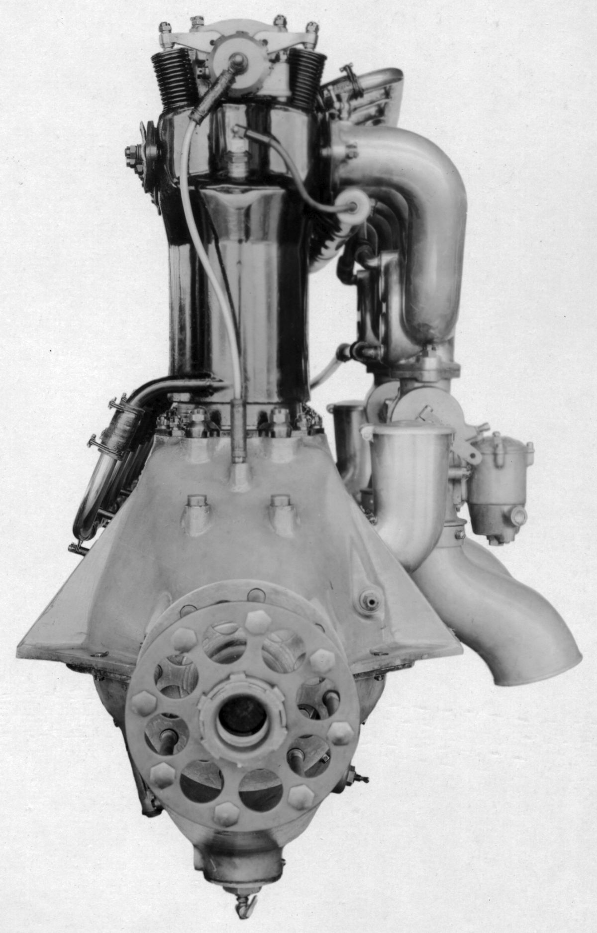
The A-1, a water-cooled vertical four with a 4.000" (101.6 mm) bore, 5.000" (127.0 mm) stroke and 251.3 in³ (4.119 l) displacement, was rated 32 hp but developed 40 hp at 1,500 rpm. The cylinders had cast-iron heads with cored water passages and were fitted with overhead inlet and exhaust valves operated by push rods and rocker arms. A sheet-steel water jacket pressed over the cylinder barrel, which was secured by long studs from lugs on the cylinder head. The hand-forged crankshaft had three plain main bearings. The connecting rods were also hand-forged, and the grey-iron pistons were fitted with three rings. Lubricating oil was forced by a gear pump into the hollow camshaft, from where it was distributed to all the main bearings. It returned to the crankcase where an oil level was maintained for splash connecting rod bearing and piston lubrication. Stromberg carburetors supplied the mixture, and Mea magnetos the ignition. Dry weight was 165 lb, length 39", width 17.5", and height 28".
The A-2, a 90° V-8 with a 4.000" (101.6 mm) bore, 4.000" (101.6 mm) stroke and 402.1 in³ (6.590 l) displacement, was 60 hp at 1,400 rpm. The cylinders were cast from semi-steel (not really steel, but a high-grade iron made from scrap iron and steel that was cheaper and slightly weaker than actual steel), with valves in head operated by push rods and rocker arms. This engine had Stromberg carburetors, Mea magnetos, and pressure lubrication. Dry weight was 260 lb, or 4.33 lb/hp. The A-2 was 42" long, 24" wide and 28" high.
The A-3 was practically identical to the A-2 except for a 1" longer stroke. It displaced 502.65 in³ (8.237 l), and was rated 80 hp at 1,400 rpm. Dry weight 290 lb, or 3.63 lb/hp.
The A-4, a 90° V-8 with a 5.000" (127.00 mm) bore and stroke, and a 785.40 in³ (12.870 l) displacement was rated l00 hp at 1,200 rpm and developed 120 hp at 1,500 rpm. Dry weight was 535 lb, or 5.35 lb/hp. Its cylinders were similar to earlier models, with overhead valves operated by push rods and rockers. Each inlet and exhaust valve had a 2.5"clear diameter. The crankshaft ran on five plain bearings, and Bosch magnetos furnished dual ignition.
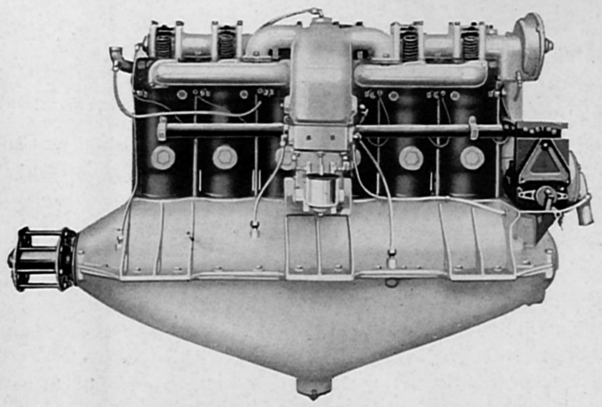
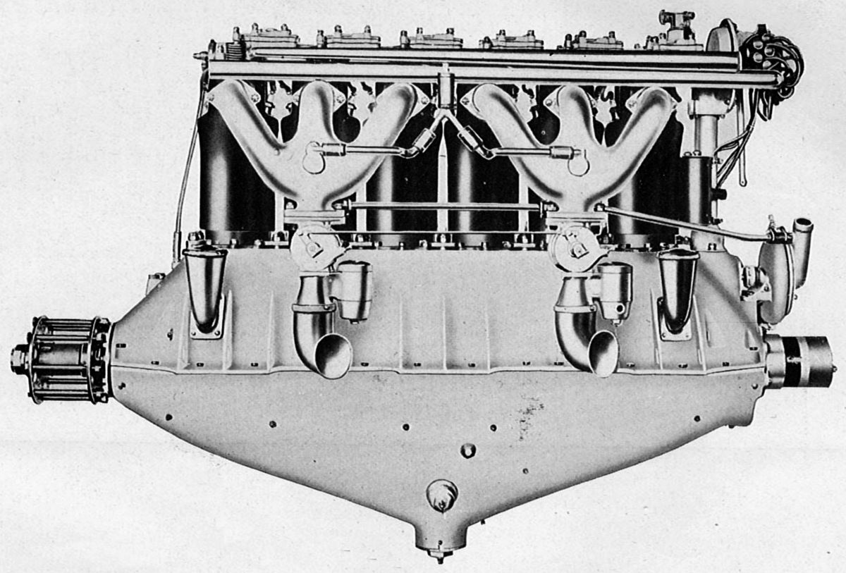
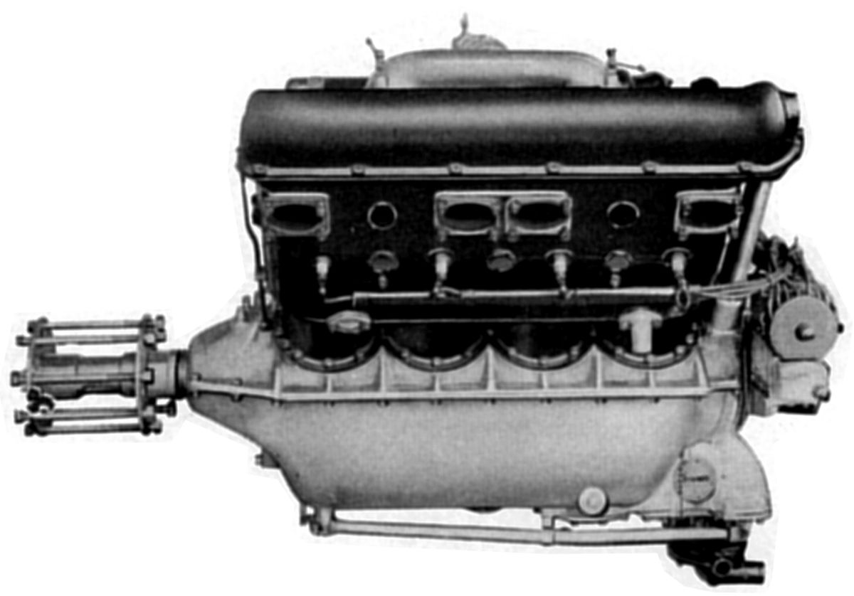
The A-5, a water-cooled vertical six-cylinder with a 5.000" (127.00 mm) bore, 7.000" (177.80 mm) stroke and 824.67 in³ (13.514 l) displacement, was rated 125 hp at 1,250 rpm and weighed 525 lb, or 4.2 lb/hp. The cast-iron cylinders had integral water jackets and were secured to the crankcase by long studs from cylinder head lugs. The overhead camshaft, in conjunction with rocker arms, operated an inlet and an exhaust valve in each cylinder, both of which were inclined to the cylinder axis. The inlet manifold was both water and oil jacketed. The crankshaft ran on seven plain main bearings, and the pistons were made of cast iron. Magnetos supplied dual ignition.
|
|
| Hall-Scott A-5-a (AEE) | |
The A-5-a, a vertical six with a 5.250" (133.35 mm) bore, 7.000" (177.80 mm) stroke, 909.20 in³ (14.9 l) displacement and 4.6:1 compression ratio, was rated 150 hp but developed 165 hp at 1,475 rpm, for a 97.5 psi average bmep. Oil consumption was 0.029 lb/hp/hr with the oil pressure maintained between 10 and 35 psi by a gear pump. Duplex Zenith carburetors were fitted. Inlet and exhaust valves had a 2.25" clear diameter and a 0.375" lift. Inlets opened 15° late and closed 45° late; exhausts opened 54° early and closed 10° late. Length was 62.5", width 24", and height 43.875".
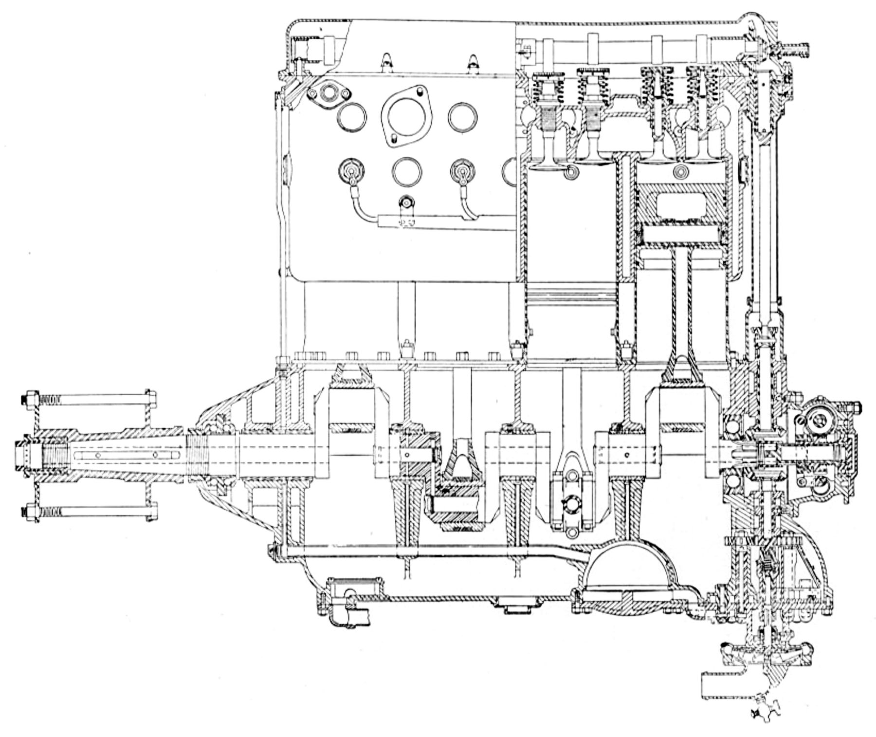
The A-7, a water-cooled vertical four that used A-5 cylinders and displaced 549.78 in³ (9.01 l), was rated 90 – 100 hp at 1,400 rpm and weighed 410 lb. Zenith carburetors were fitted, and two Dixie magnetos supplied dual ignition. The H-section connecting rods employed two-bolt caps. The aluminum pistons had six ribs below the head and were fitted with three rings each. A gear pump forced oil from the sump through a strainer to a jacket around the inlet manifold, and then to the main crankcase distributor pipe. An independent direct-drive rotary oiler fed to each cylinder based on engine speed and a manually hand adjusted sight feed oiler quantity adjustment.
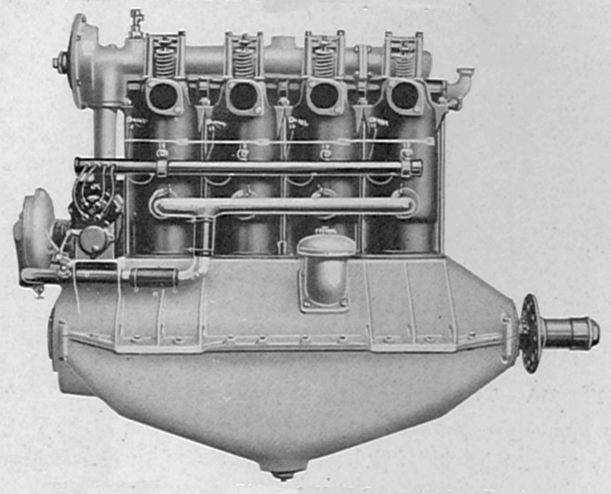 |
| A-7-a (AEE) |
The A-7-a, a vertical four with A-5-a cylinders displacing 606.13 in³ (9.933 l), was rated 100 hp at 1,400 rpm, but developed 110 hp at 1,400 hp and weighed 420 lb, or 3.81 lb per hp. The individual semi-steel cylinders used an overhead camshaft and rocker arms to actuate two 2.25" valves with 0.375" lift. A 10 psi oil pressure was maintained by a gear pump. Oil consumption w2as 0.039 lb/hp/hr. Either Miller or Zenith carburetors were fitted. Average fuel consumption was 0.62 lb/hp/hr. The 5-plane-main-bearing crankshaft had H-section connecting rods with two-bolt caps. Each aluminum piston was fitted with three rings above the piston-pin. A centrifugal pump with a bronze impeller circulated cooling water.
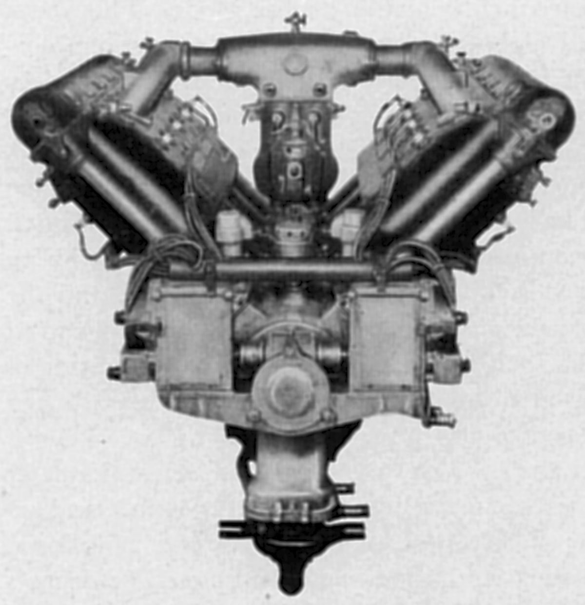
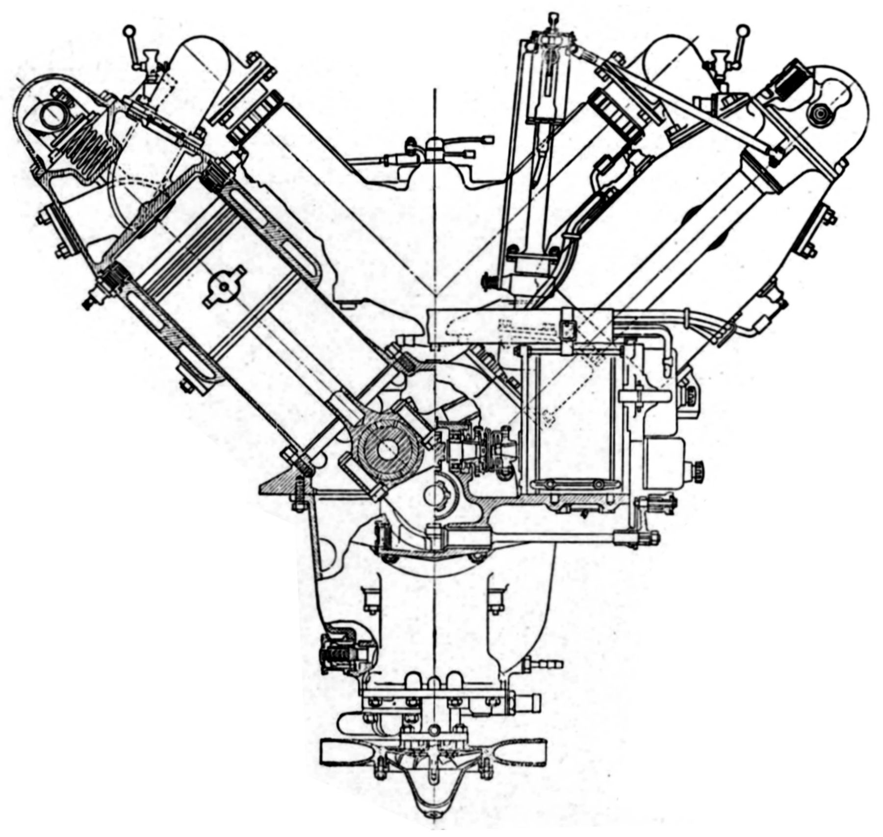
 |
 |
| A-8 (AEE) | |
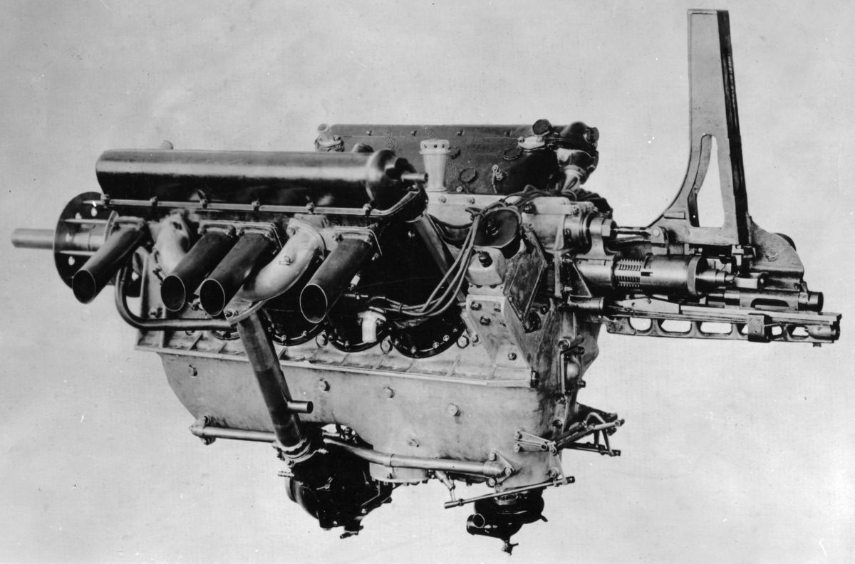
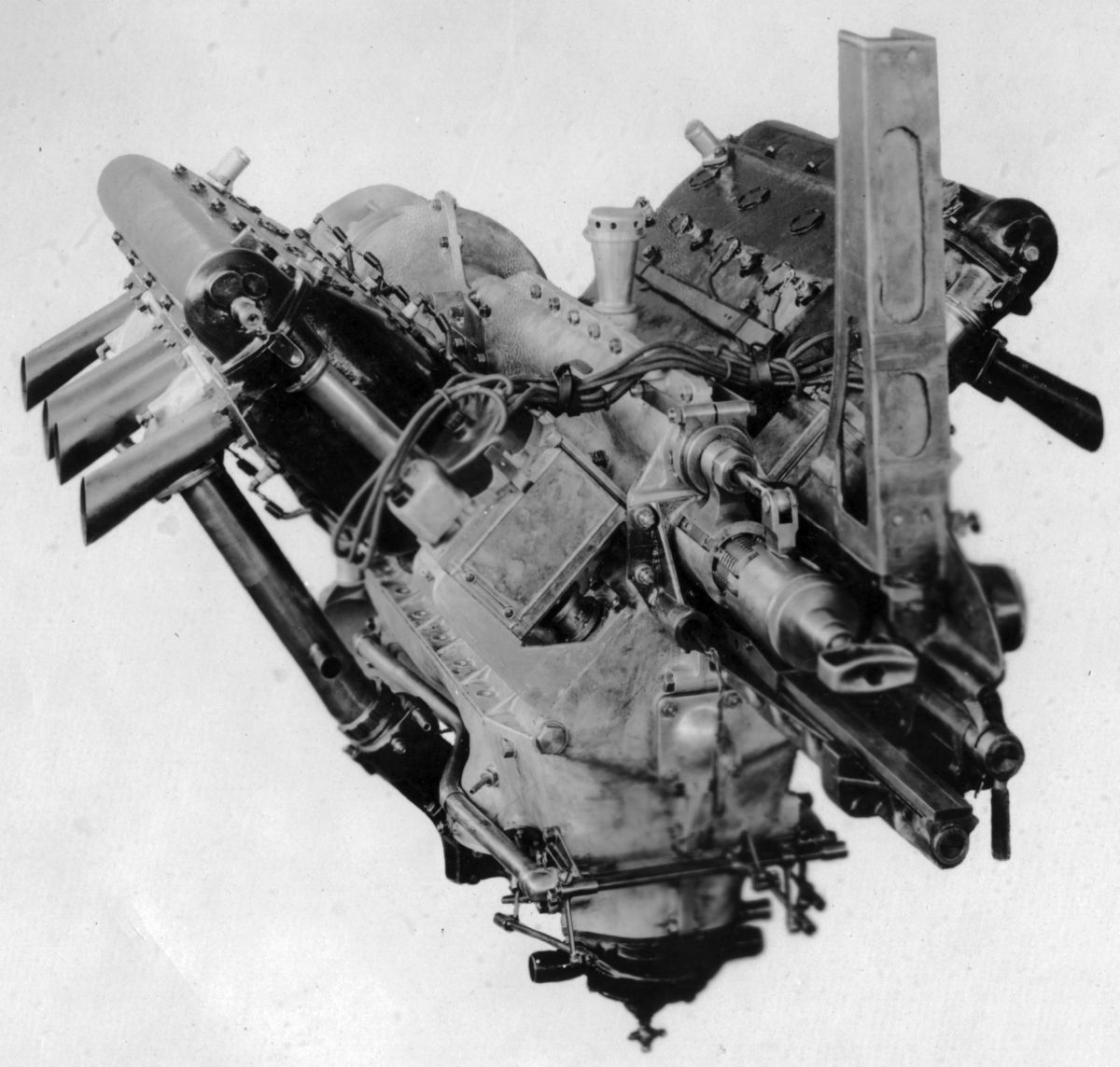
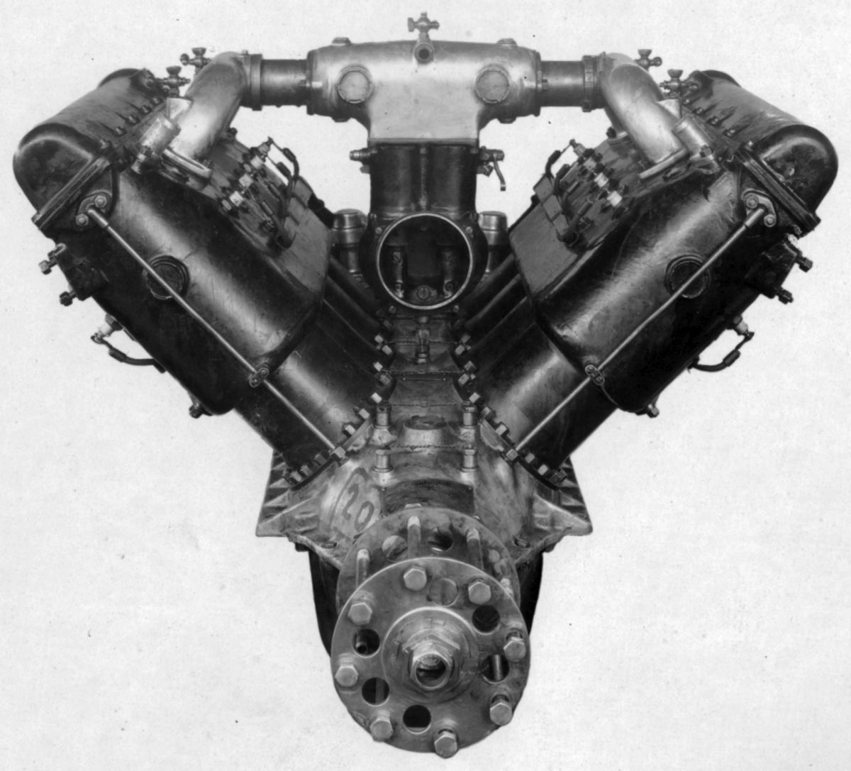
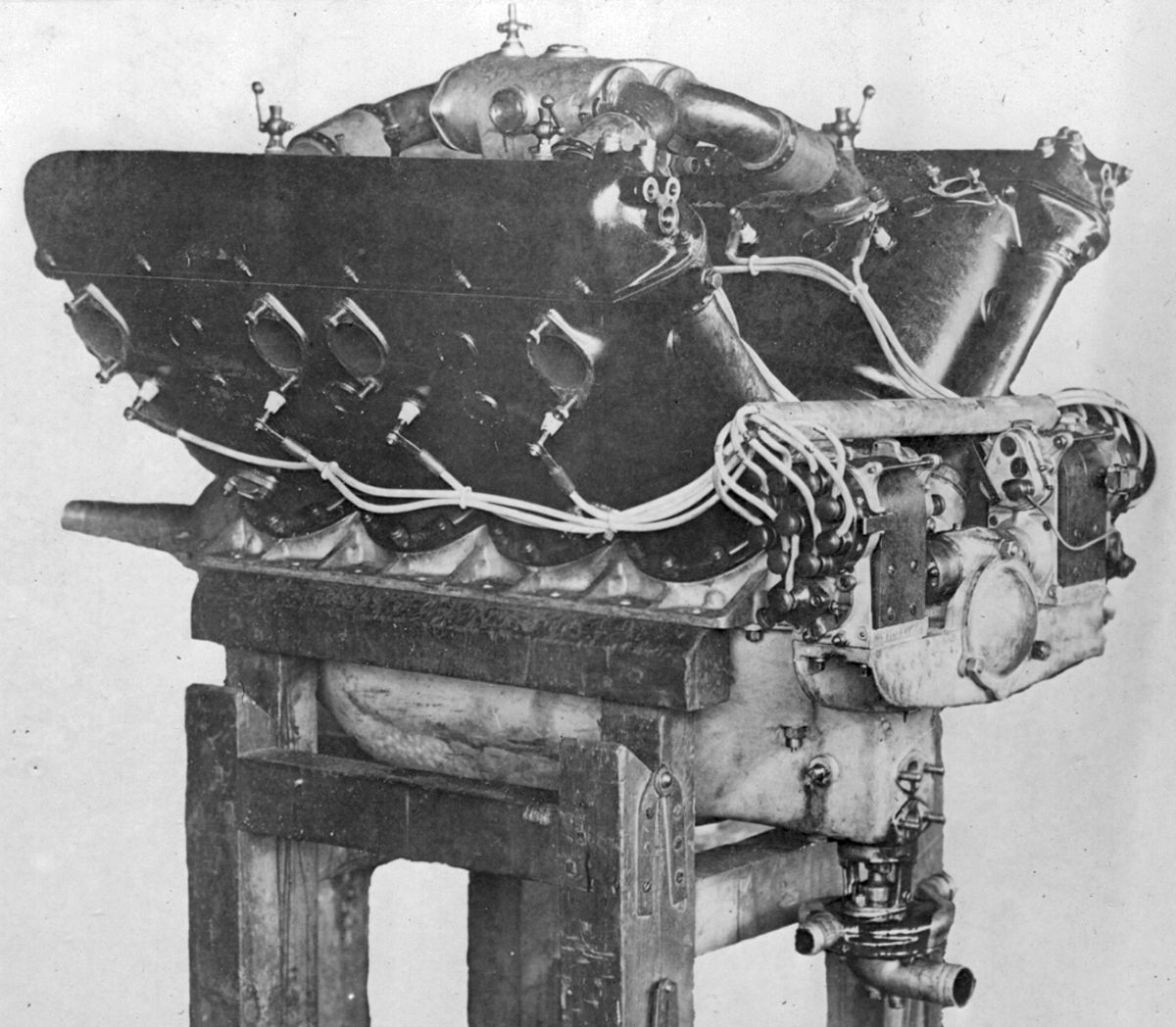
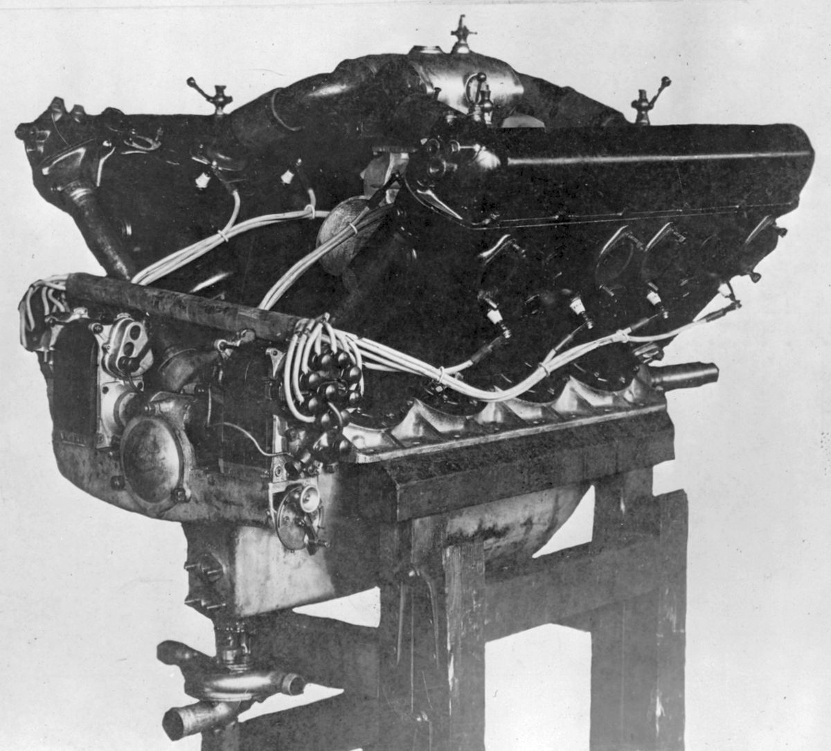
The A-8, which was ready for test before 1 May 1917 when Elbert Hall was called to Washington, DC to assist in the Aircraft Production Program, was a water-cooled 60° V-12 with a 5.000" (127.00 mm) bore, 7.000" (177.8 mm) stroke, and 1649.34 in³ (27.03 l) displacement. It produced 450 – 500 hp and weighed 1,000 lb. The cylinders similar to A-5 and A-7 models. The seven-main bearing crankshaft featured H-section connecting rods. Two water-pumps, driven from each camshaft drive shaft, circulated cooling water to each cylinder bank independently. Two magnetos and two spark plugs per cylinder provided dual ignition.
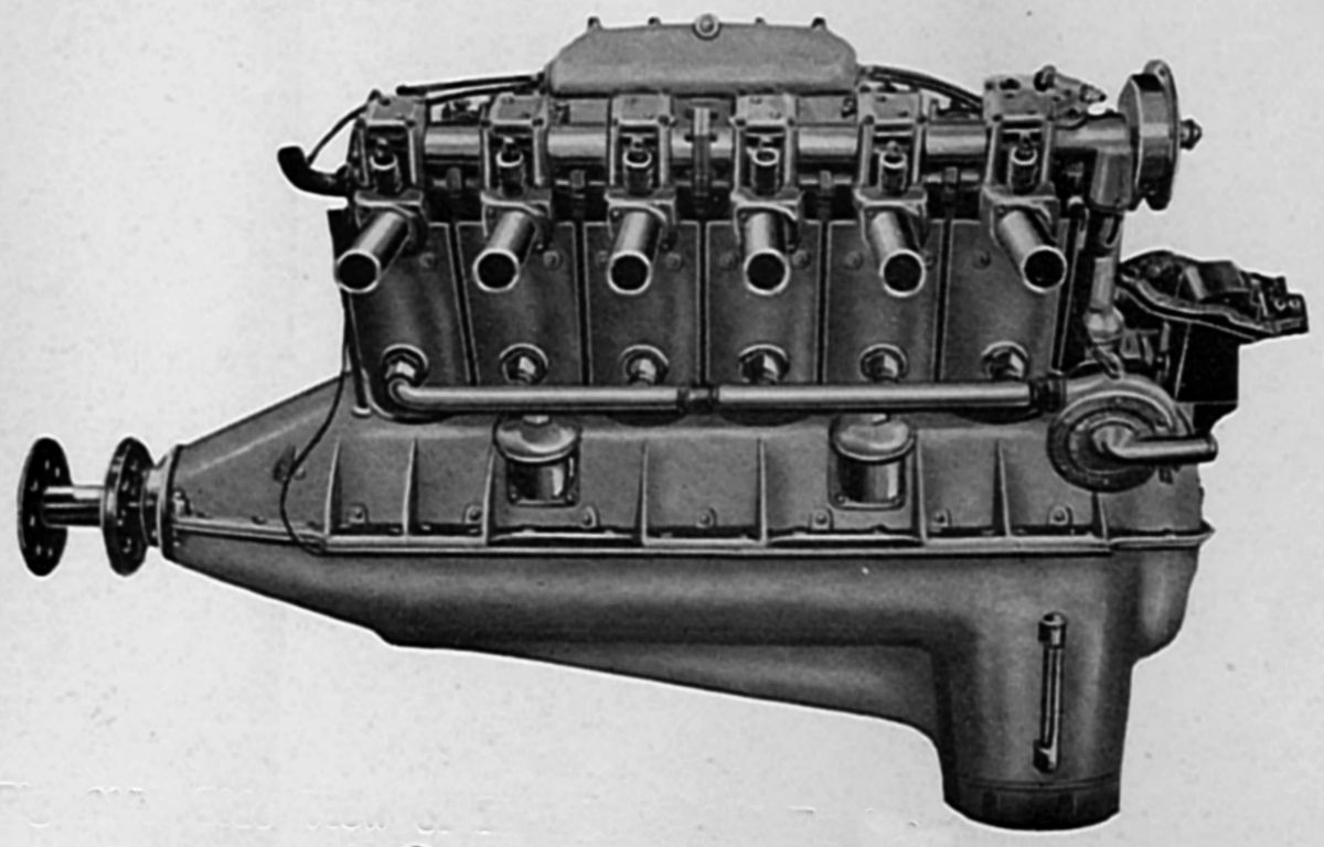
The Hall-Scott L-4 and L-6 were post-WWI developments using Liberty cylinders and valve gear. Their bores were 5.00" (127.00 mm), strokes were 7.000" (177.80 mm), displacements were 137.44 in³ (2.25 l) per cylinder and compression ratios about 5.4:1.
The L-4, displacing 549.78 in³ (9.01 l), was rated 125 hp, but developed 130 hp at 1,675 rpm from 380 lb, or 3.05 lb/hp.
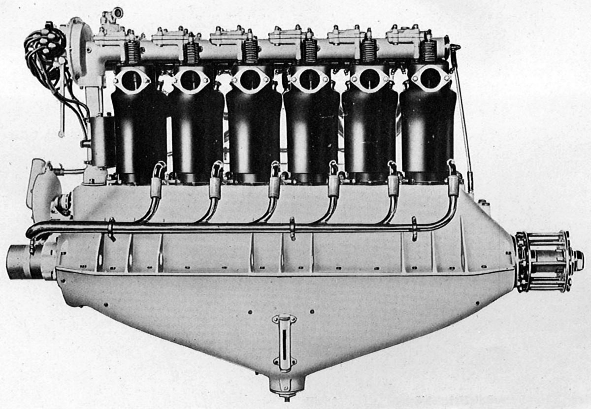
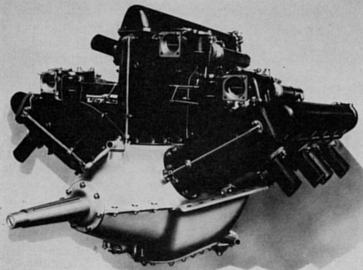
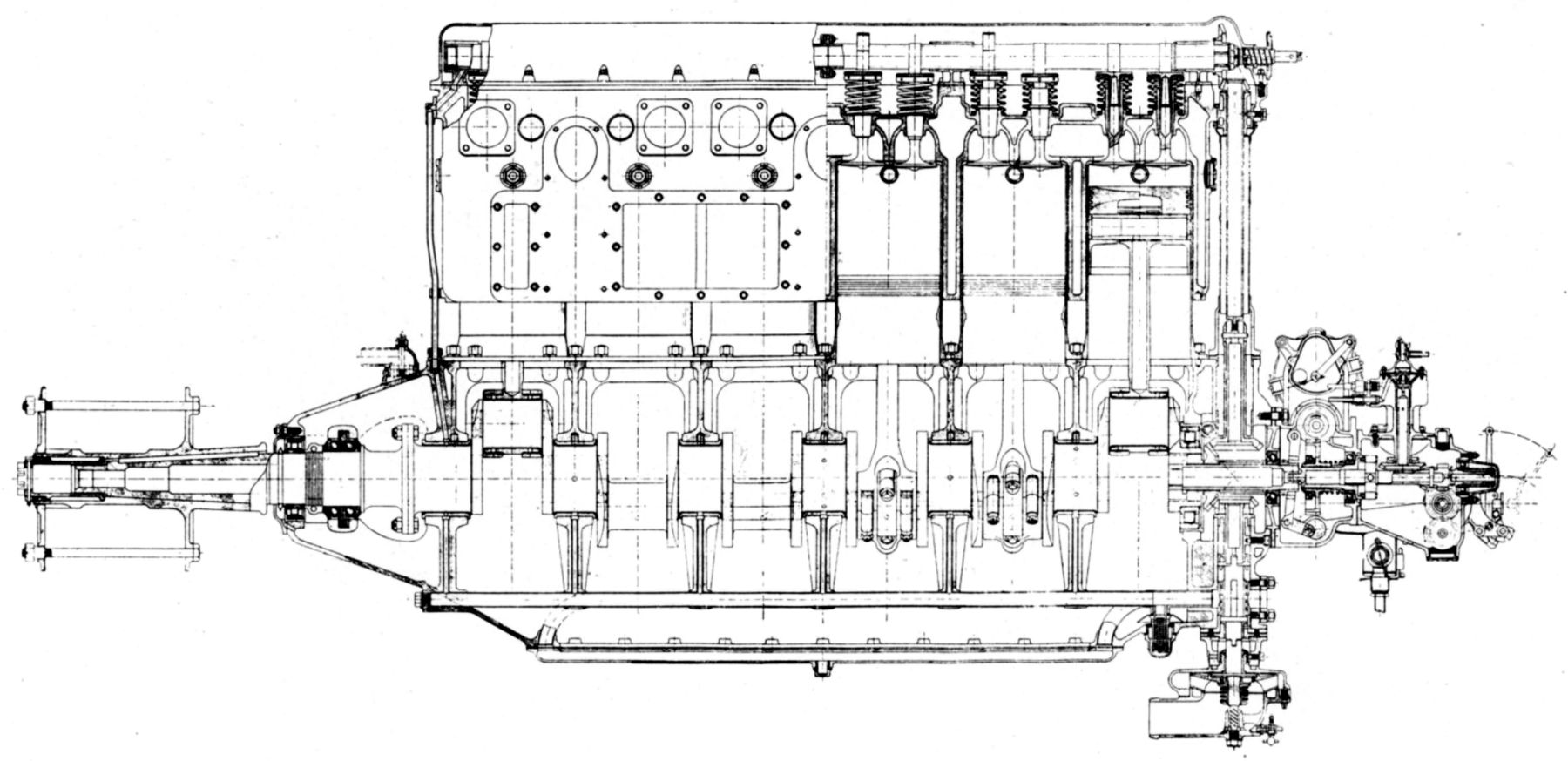
The L-6, displacing 824.67 in³ (13.52 l), was rated 200 hp, but developed 224 hp at 1,700 rpm and 244 hp at 1,830 rpm Fuel consumption was 0.55 lb/hp/hr. Miller multi-jet carburetors with barrel throttles furnishing the mixture. The oil supply, carried in the oil sump, was circulated at about 40 psi by a gear pump situated in the sump and maintaining approximately 40 lb pressure to the main bearings. Another pump supplied fresh oil to the system. The six-throw, seven-main-bearing crankshaft had H-section connecting rods with four-bolt caps. A Liberty piston with an additional eep groove and oil holes below the bottom ring was used. A Delco battery system, generator and distributor furnished ignition. Dry weight was 546 lb plus an additional 25 lb water. The L-6 was 65" long, 18.25" wide at the support centerlines, and 44" high.
 |
 |
 |
 |
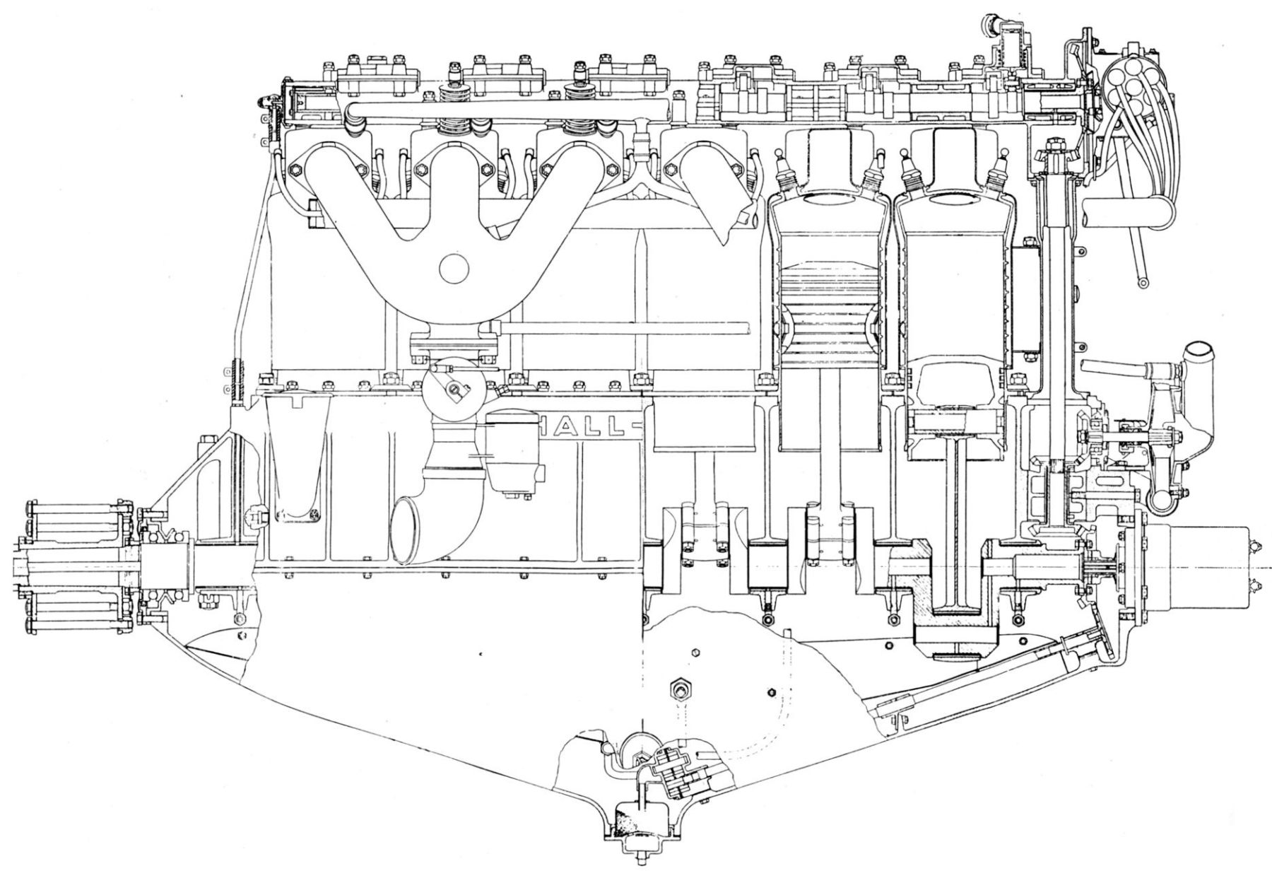 |
| Hall-Scott L-6 (AEE) | ||||
 |
| H & S 35 hp (AEE) |
Hansen & Snow
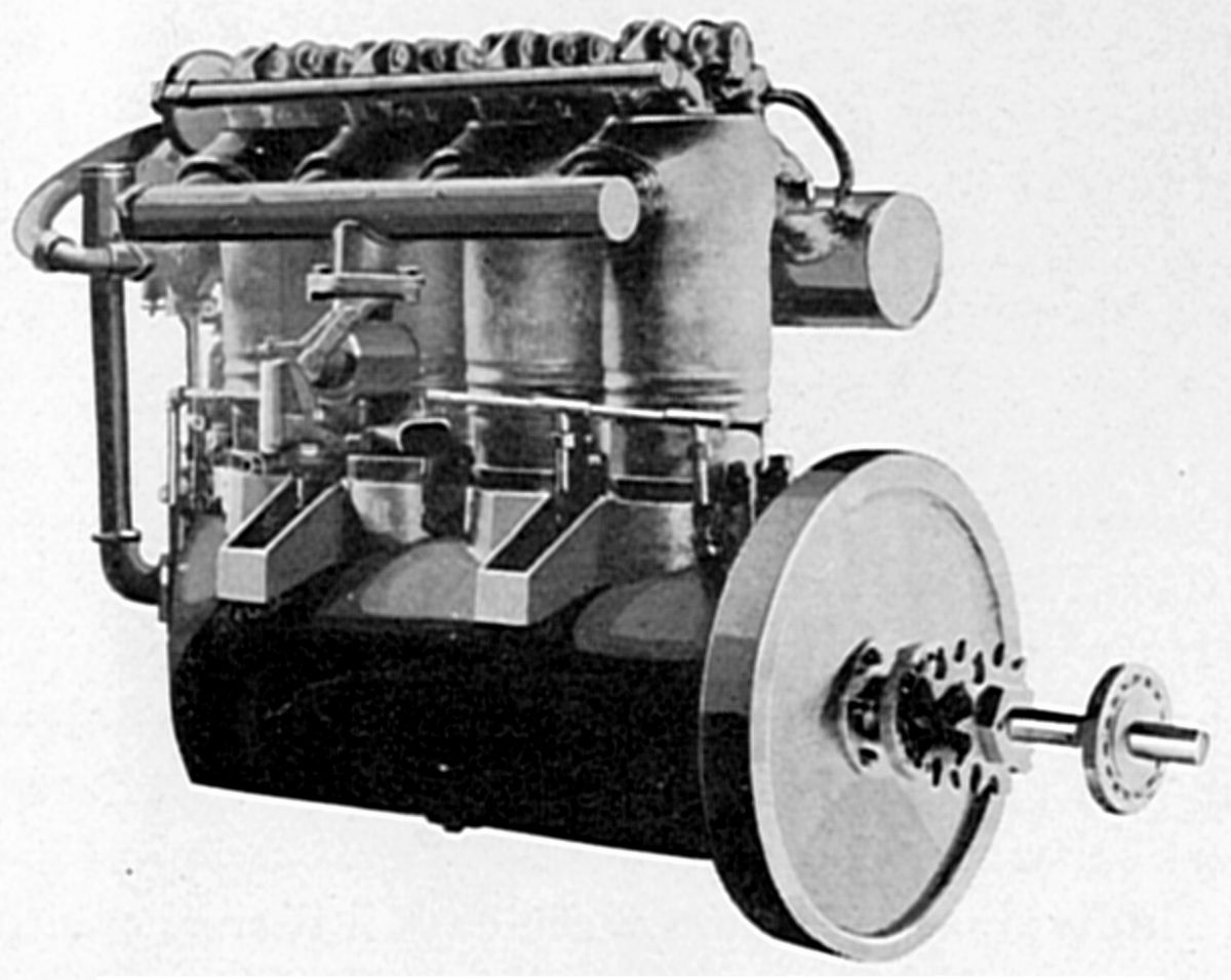
W. G. Hansen and L. L. Snow of Pasadena, California built a water-cooled vertical four-during 1910. This engine was flown in an early Wright biplane and later powered the first U.S. passenger airship, the White City, designed by Roy Knabenshue, who also had been responsible for talking the Wright Brothers out of burning their 1903 airplane and making it available for historical purposes. L. L. Snow was a U. S. Army Air Service officer and pilot for a number of years, his service beginning WWI's early days. For a period following the Armistice signing, he was in charge of cooling system development at the Engineering Division, McCook Field, Dayton, Ohio.
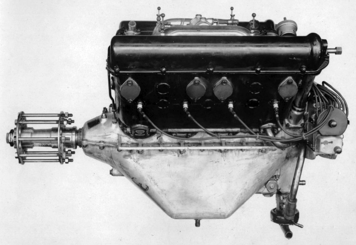
The Hansen & Snow engine, with a 4.000" (101.6 mm) bore, 4.500" (114.3 mm) stroke, 226.19 in³ (3.71 l) displacement and 5:1 compression ratio, was rated 35 hp at 1,200 rpm. Dry weight (without flywheel) was said 105 lb, or 3 lb/hp. The engine was 24" long, 11" wide, and 24" high. The individual cast-iron cylinders, with electrolytically-deposited copper water jackets, had dome-shaped cylinder heads and 2.25" clear-diameter valves inclined at 60°. These were operated by an overhead camshaft and rocker arms. Five Hess-Bright ball bearings supported the camshaft. The H- section shank connecting rods attached cast iron pistons with ribs underneath the head. Dry-sump lubrication with a reserve oil supply in the crankcase supplied pressure-fed oil to all bearings by a gear pump. A Stromberg carburetor furnished the mixture, and a Bosch magneto the ignition.
 |
 |
| Harriman Four, Six (AEE) | |
Harriman
The Harriman Motors Company of South Glastonbury, Connecticut, designed and built its first airplane engine in 1909. Harriman engines were frequently used in pioneer flights, and were claimed to have been the third successful U.S. airplane engines produced in the United States. Harriman engines were all water-cooled inlines.
The individual cast-iron cylinders were machined inside and out before welded-on sheet-steel water jackets surrounding the barrels were attached. The cylinders were screwed into the crankcase and checked with a lock nut. The valves were seated in removable cages that stood vertically in the cylinder head, and they were operated by an overhead camshaft and roller rocker arms that actuated adjustable valve stem caps. Auxiliary exhaust ports at the cylinder bottoms supplemented and relieve the main exhaust valves. Aluminum crankcases featured constant-level splash pockets at each crankpin, which contained a reservoir from which oil was forced to the main bearings by a pump. Harriman crankshafts had main hearings on each side of the crank throws, and H-section connecting rods attached cast-iron pistons fitted with three wide rings. Cooling water was circulated by an aluminum and bronze rotary pump. The inlet water header was made from aluminum and attached to the jackets by hollow bronze cap screws. Schebler carburetors and Eisemann magnetos were standard equipment.
The 30 hp Harriman four was 31.125" long, 16.25" wide and 24.938" wide.
A larger four-cylinder model, rated 60 hp at 1,350 rpm, had a 5.000" (127.00 mm) bore and stroke and displaced 392.7 in³ (6.44 l). Fuel consumption was 0.68 lb/hp/hr and oil consumption was 0.037 lb/hp/hr. Dry weight was 240 lb, or 4 lb/hp. Length was 34.75", width was 17.5", and height 28.938".
The six-cylinder model, which used 60-hp cylinders and displaced 589.05 in³ (9.65 l), was rated 100 hp at 1,400 rpm and weighed 355 lb, or 3.55 lb/hp. Fuel consumption was 0.74 lb/hp/hr. Length was 53.438", width was 17.5", and height was 30.625".
 |
 |
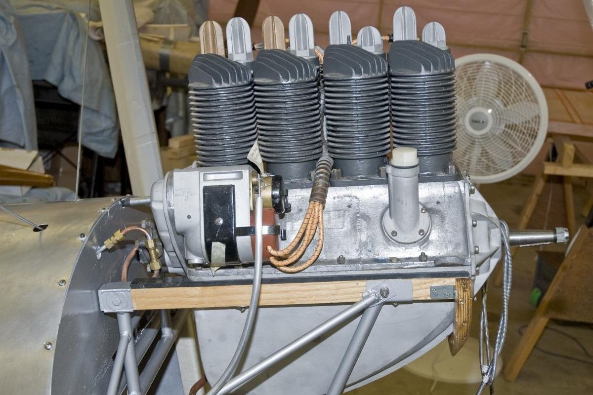 |
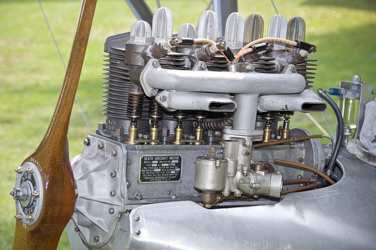
| Heath-Hernderson B-4 (REL) | ||
Heath-Henderson
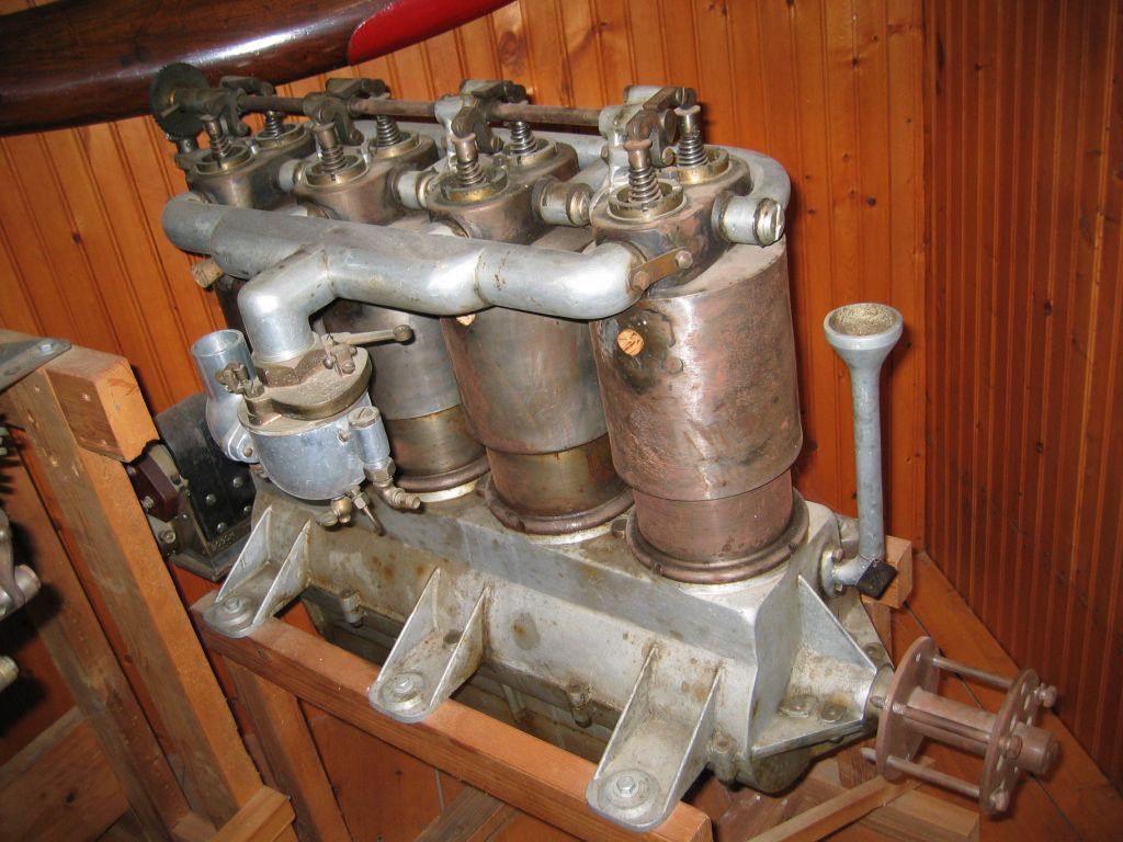
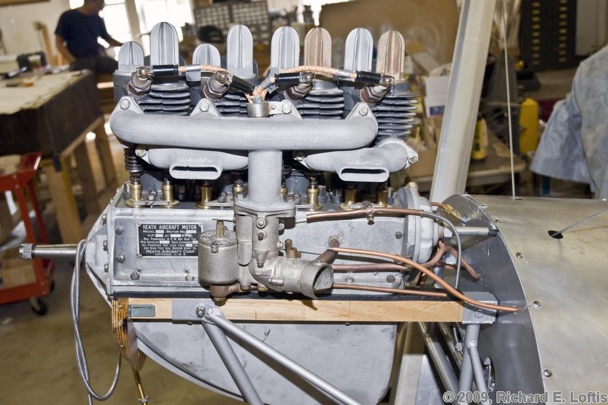
The original Heath Aircraft Corporation of Chicago, Illinois and Niles, Michigan was succeeded by the International Aircraft Corporation, which was succeeded by the Heath Aviation Company of Benton Harbor, Michigan. These companies converted Henderson air-cooled inline four motorcycle engines to aircraft use. Several were installed in Heath Super Parasols, which attracted considerable air-race attention by winning free-for-all events against fields of higher powered aircraft. The conversion involved substituting bearings that retained oil longer, installing a larger oil pump that delivered higher pressure, and deepening the lower crankcase was deepened to increase its capacity. Silchrome-steel exhaust valves with larger stems were substituted, and aluminum-alloy port plugs were install to dissipate more heat. The number two cylinder's compression ratio was lowered to avoid preignition from increased compression due to carbon formation in a cylinder shielded more than the others from the cooling air blast.
The Heath B-4 engine, with a 2.75" (69.85 mm) bore, 3.50" (88.9 mm) stroke, 83.15 in³ (1.36 l) displacement and 4.6:1 compression ratio, developed 27 hp at 2,700 rpm and 30 hp at 3,000 rpm. Complete with propeller, the engine weighed 119 lb. A gear-type pump maintained an oil pressure between 50 and 100 psi and the sump capacity was six quarts. Fuel consumption was 0.72 lb/hp/hr, and the oil consumption was 0.017 lb/hp/hr. The engine was 25.25" long, 14.5" wide and 24" high. The one-piece cylinders were cast with integral cooling fins. Three rings were used on aluminum alloy full-skirt pistons. The H-section shank connecting rod big ends were fitted with bronze-backed white-metal-lined bearings. The four-throw one-piece forged crankshaft was carried upon three white-metal-lined bronze bearings. Either single or dual ignition was furnished by Bosch magnetos, and a Zenith TAX carburetor provided the gas mixture. Inlet valves opened 14° early and closed 68° late; exhaust valves opened 42° early and closed 22° late.
Hiero
Otto Hieronimus (26 July 1879 – 8 May 1922) was a German - Austrian automobile designer and successful racing driver. Son of the Benz Cologne representative, he worked at Benz in Mannheim and attended the Hildburghausen technical center. Hieronimus worked at the Austrian Laurin and Klement Automobile works in 1908 and 1909, where he began the water-cooled Hiero engine line with a vertical four weighing 234 lb that produced 50 – 60 hp. This engine had a single inlet and exhaust valve in each cylinder actuated by a common push/pull rod from a camshaft mounted on the crankcase side. Fuel consumption was 0.606 lb/hp/hr and oil consumption was 0.042 lb/hp/hr. In May 1911 he designed the Hiero aircraft engines named after him.
From 1910 to 1913, a similar Hiero water-cooled vertical four was produced in Germany by Werner and Pfleiderer. It used a separate push rod to operate each valve. With a 130 mm (5.118") bore, 150 mm (5.906") stroke and the displacement 7.964 l (485.99 in³), it was rated 85 – 95 hp at 1,700 rpm and weighed 320 lb. Fuel consumption was 0.55 lb/hp/hr and oil consumption was 0.033 lb/hp/hr.
A water-cooled vertical eight introduced in 1914 delivered 200 – 220 hp, weighed 573 lb, and consumed fuel at 0.507 lb/hp/hr.
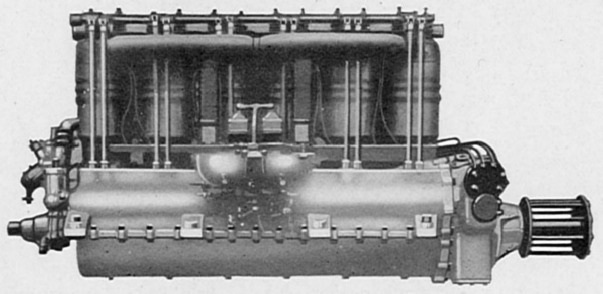 |
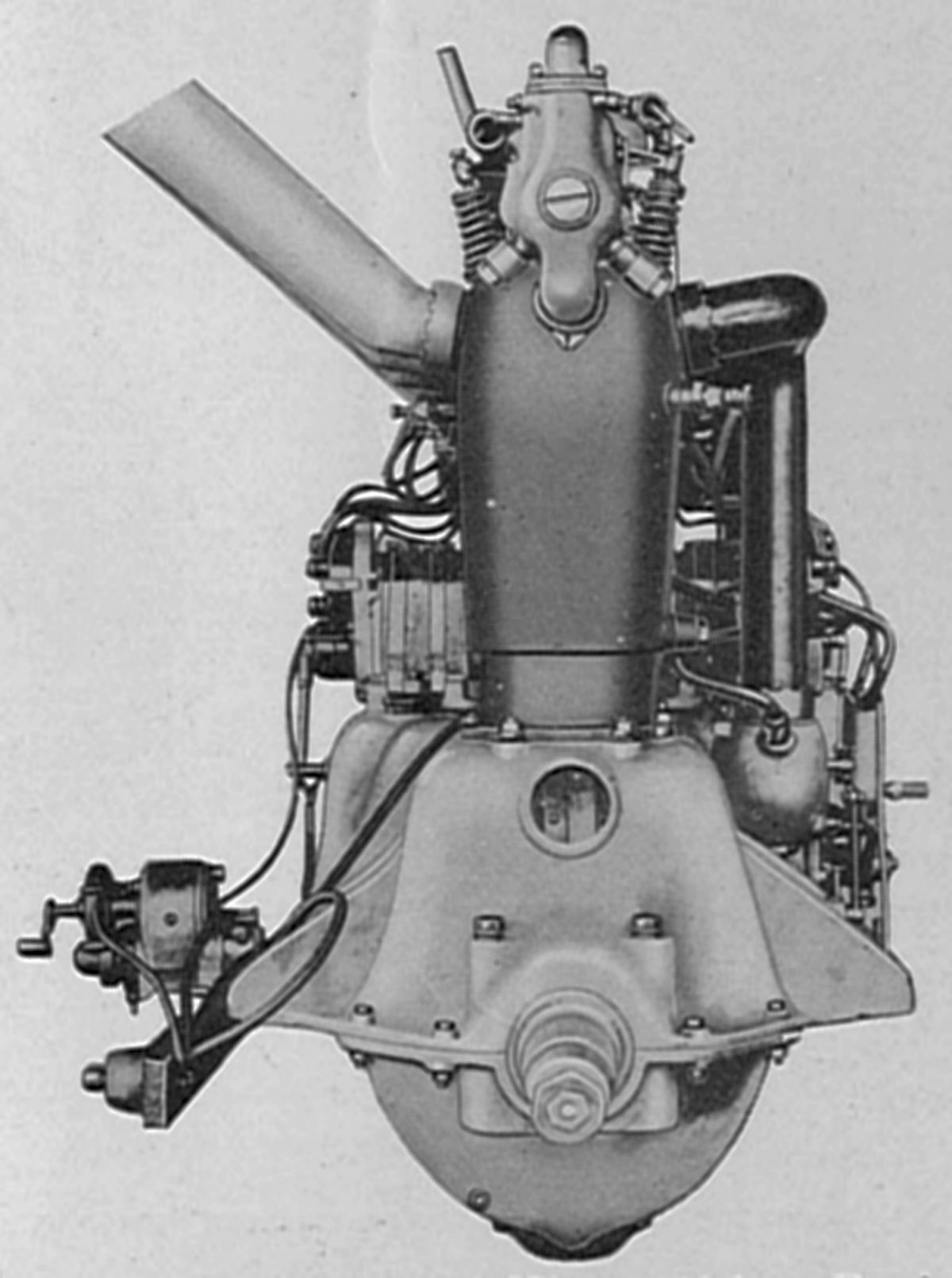
| Hiero 145 hp (AEE) |
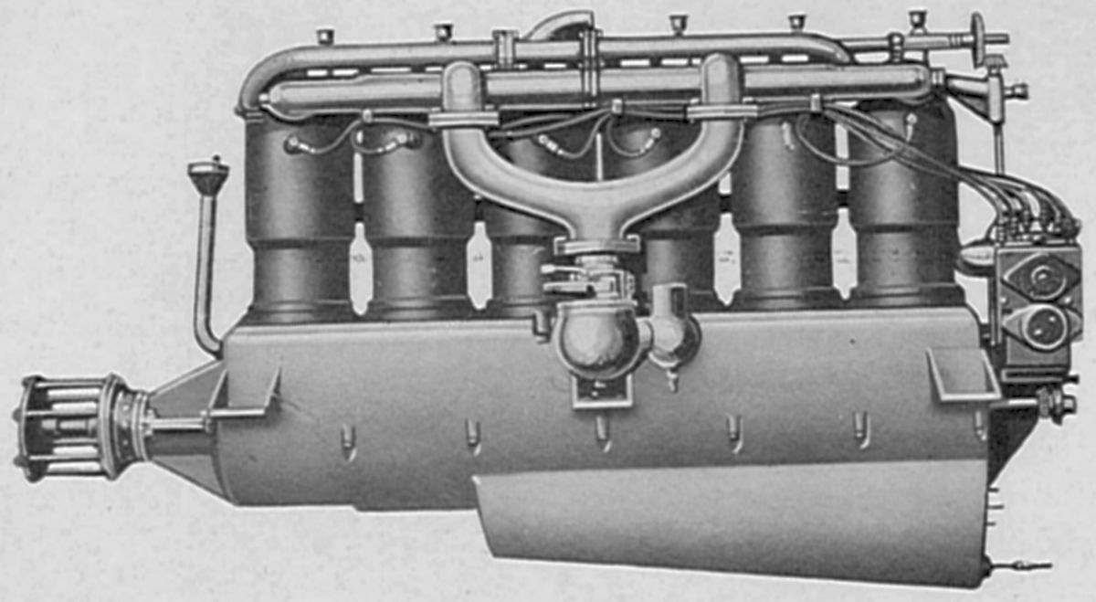
Also around 1914, the first Hiero water-cooled vertical six, with a 130 mm (5.118") bore, 160 mm (6.299") stroke and 12.742 l (777.56 in³) displacement was built. It was rated 145 hp at 1,400 rpm.
 |
 |
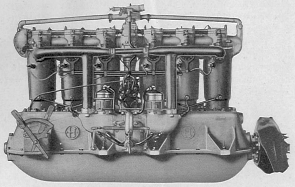 |
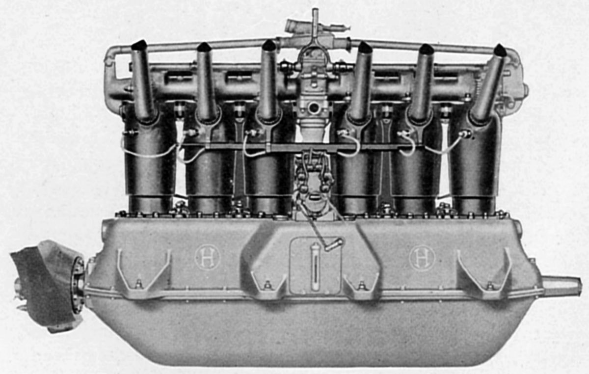
| Hiero II 200 hp (AEE) | ||
The Hiero II, A larger water-cooled vertical six was built during 1915 by Essler, Warschalowski and Company of Vienna, Austria, under license by the Loeb Motors Works of Berlin, as well as Breitfield and Danek of Prague. With a 135 mm (5.315") bore, 180 mm (7.087") stroke and 15.459 l (943.37 in ³) displacement, it was rated 200 hp at 1,400 rpm. Fuel consumption was 0.595 lb/hp/hr, and the dry weight was 695 lb, or 3.47 lb/hp. Individual steel cylinders with welded-on sheet-iron jackets had single inlet and exhaust valves operated via rocker arms and an overhead camshaft, enclosed in an aluminum housing, and driven by a vertical shaft from the engine center. The inlet valve opened 10° late and closed 35° late; the exhaust valve opened 50° early and closed 5° late. The six-throw, seven-main-bearing crankshaft was supported in seven bronze bearings by caps attached the aluminum alloy crankcase. Some engines were made with a propeller hub on crankshaft each end to accommodate either tractor or pusher propellers; others featured a starting clutch at one end. The H-section connecting rods had two-bolt caps. Aluminum alloy pistons were reinforced under the head by cylindrical and star-shaped ribs, and were fitted with four rings. Two carburetors furnished the mixture and two cross-mounted magnetos furnished the ignition. Piston-type oil pumps located in the sump were divided into two groups. The pressure group had eight cylinders, seven for the crankshaft bearings and one for the camshaft and its vertical drive shaft. The two-cylinder scavenging had two cylinders. A centrifugal pump circulated cooling water.
The Hiero IV, another water-cooled vertical six constructed by Breitfield and Danek of Prague, was brought out in 1916. With a 140 mm (5.512") bore, the 180 mm (7.087") stroke, 16.625 l (1014.52 in³) displacement and 5.2:1 compression ratio, it produced 230 – 240 hp from a 737-lb dry weight. Each cylinder had four valves operated by an overhead camshaft driven from the engine center. A special Schiske duplex carburetor was standard equipment.
During 1918, a water-cooled vertical six with a 155 mm (6.102") bore, the 200 mm (7.874") stroke and 22.643 l (1,381.76 in³) displacement weighing 882 lb was produced. It was rated 300 – 320 hp at 1,400 rpm.
By 1918, the Hiero II output had been increased to 240 – 250 hp with no dimensional change or weight increase. This was probably due to a higher compression ratio.
Two water-cooled Hiero engines were developed too late for WWI service. One was a vertical four with a 160 mm (6.299") bore, 150 mm (5.906") stroke and 12.064 l (736.19in³) displacement, weighing 463 lb and producing 180 – 190 hp. A vertical six with the same bore and stroke displacing 18.096 l (1,104.29 in³) produced 270 – 280 hp and weighed 507 lb.
Hiero later developed an air-cooled horizontally-opposed two-cylinder with a 140 mm (5.512") bore, the 180 mm (7.087") stroke and the 5.542 l (338.19 in³) displacement weighing 176 lb. It was rated 35 – 40 hp at 1,400 rpm with a 0.485 lb/hp/hr fuel consumption and 0.015 lb/hp/hr oil consumption.
Hispano-Suiza
Societe d'Exploitation des Materiels Hispano-Suiza, originally known as La Societe Francaise Hispano-Suiza, presented the first Hispano-Suiza aircraft engine in Spring 1916. Designed by Swiss engineer Mark Birkigt, the Hispano-Suiza aircraft engine line introduced several innovations, including monobloc cylinder bank construction, single gear-driven overhead camshafts, and enclosed valve gear. By August 1916, the Hispano engines had been installed in Spad airplanes and sent to the WWI Front, where their value was convincingly demonstrated. The Hispano design's early success resulted in other types being developed, but the facilities were not sufficient at that time to produce the numbers required. Other French firms, as well as the British Wolseley Motors Limited, and the U.S. Simplex Automobile Company, were granted manufacturing rights. French and U.S. Hispano-Suiza model designations differed to avoid confusion, but the early engines were practically identical.
The Wright-Martin Aircraft Corporation of New Brunswick, New Jersey, took over the Simplex Automobile Company, adapted Hispano-Suiza engine designs to U.S. manufacturing methods, and produced them in quantity. Later, the U.S. Government subsidized a plant at Long Island City, New York to produce the Model H engine, a copy of a French design that delivered higher power. Wright-Martin was renamed the Wright Aeronautical Corporation (WAC) after the Armistice was signed and moved to a plant in Paterson, New Jersey. The WAC engines were known for a time as Wright-Hispano's but later were called Wright engines, with WAC insisting that the improvements effected during development entitled recognition as an American product. All Hispano-Suiza engines were licensed under the Birkigt patents, which covered features extremely vital to the engine as a whole.
 |
 |
 |
 |
 |
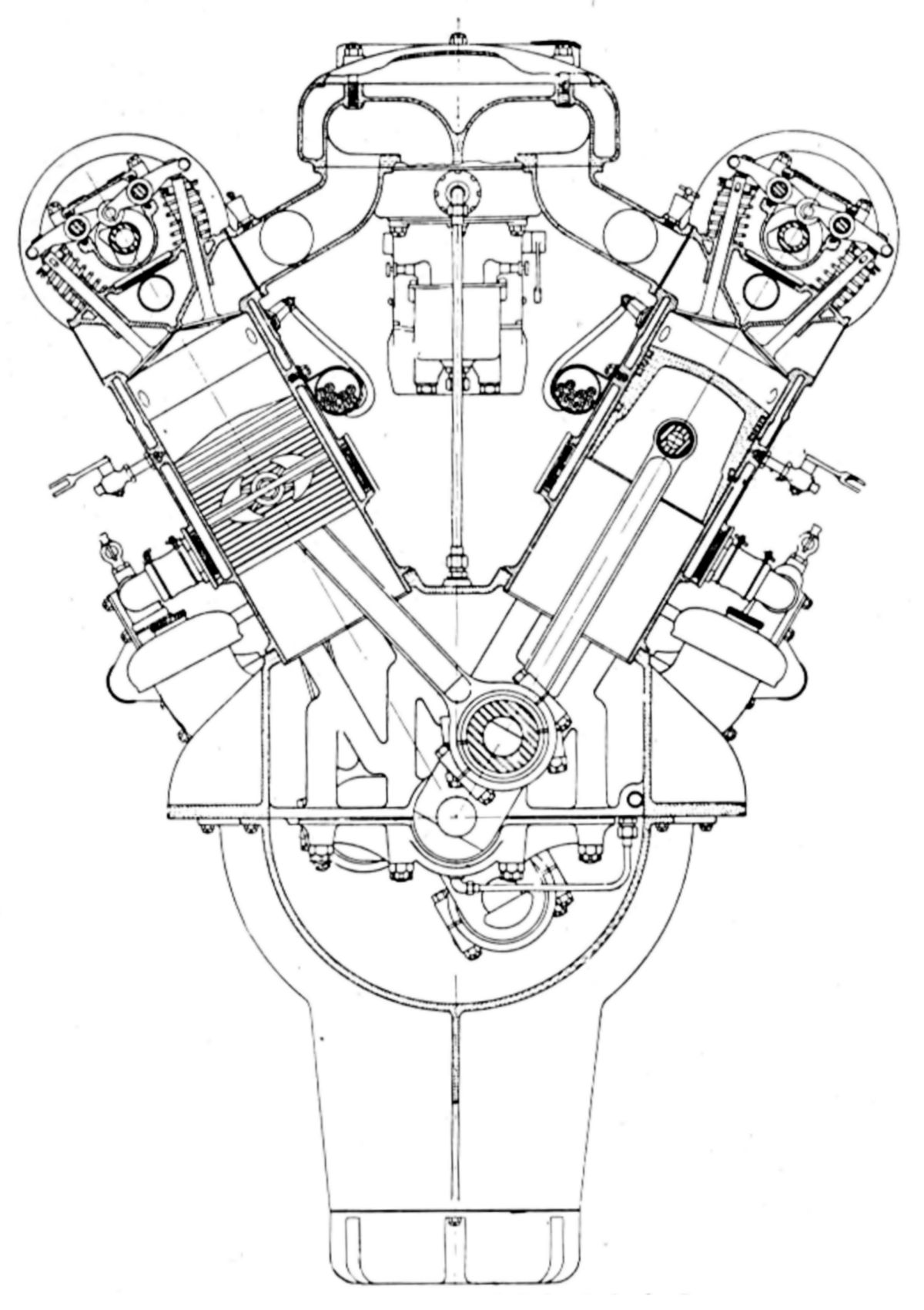
 |
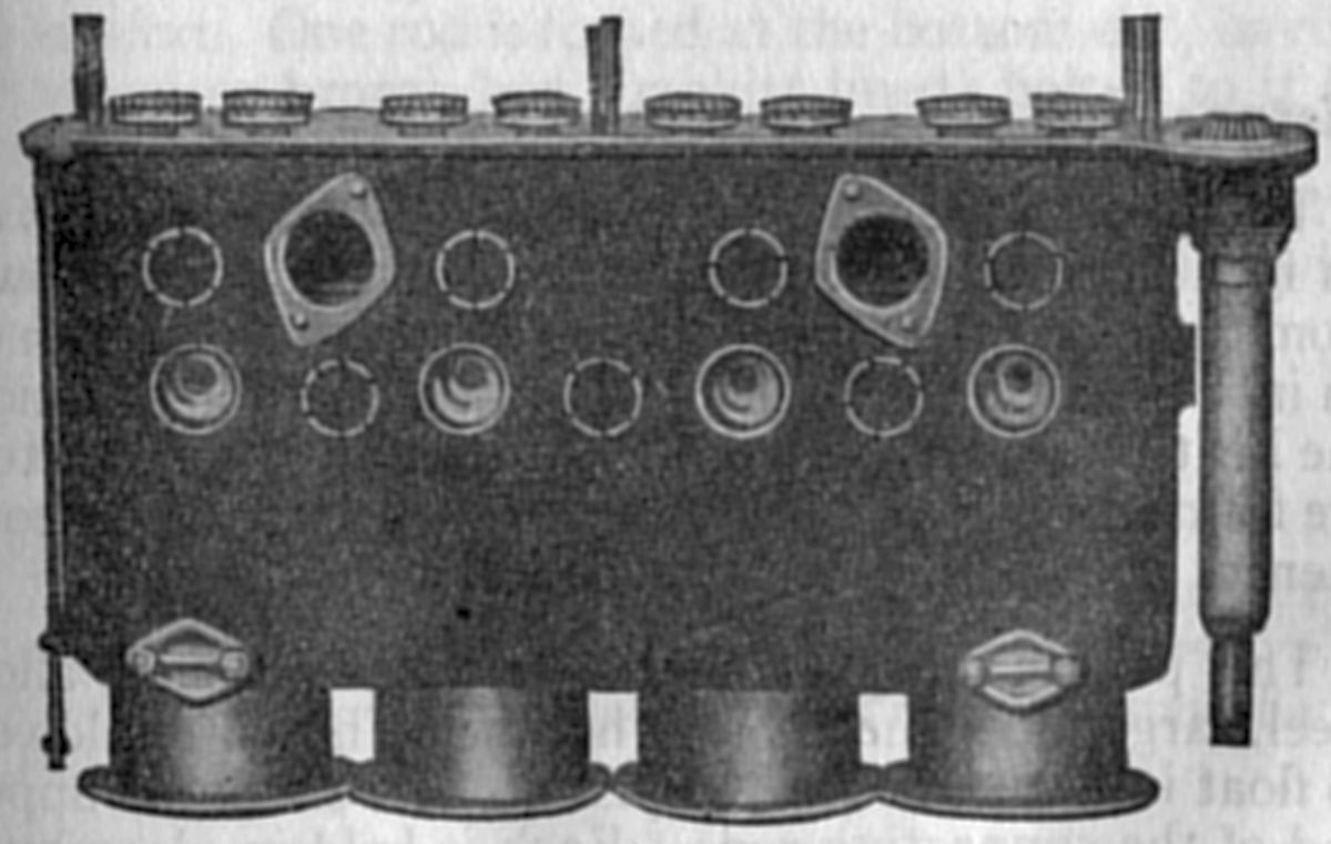
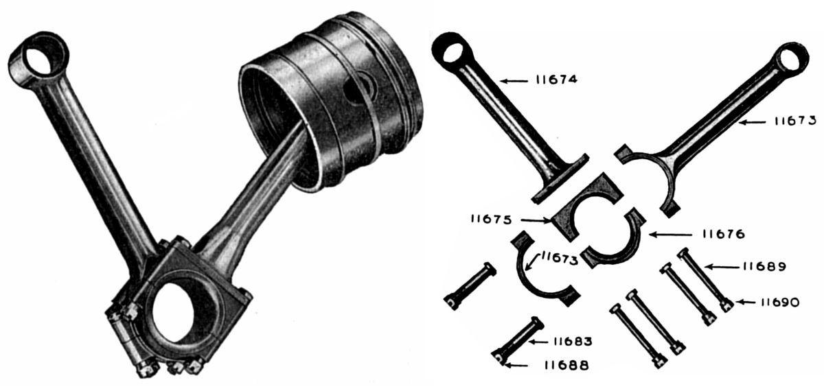
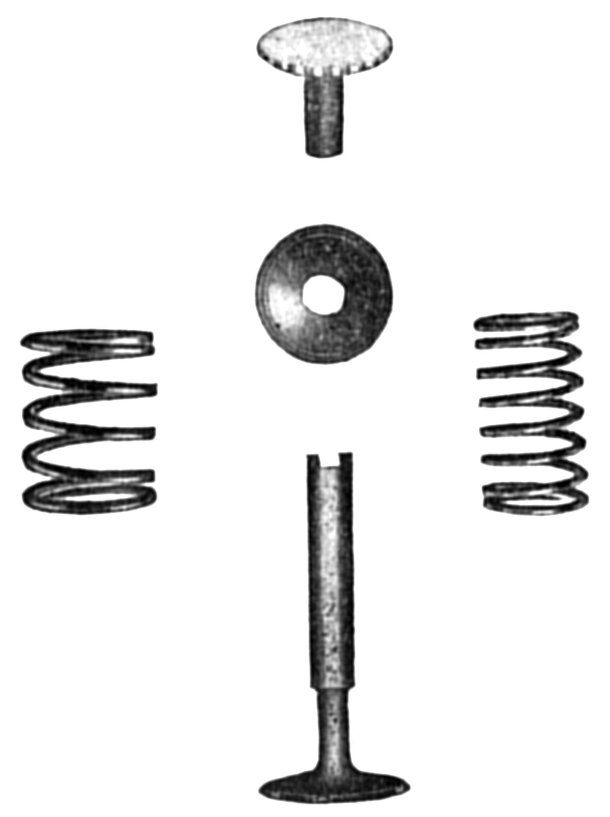
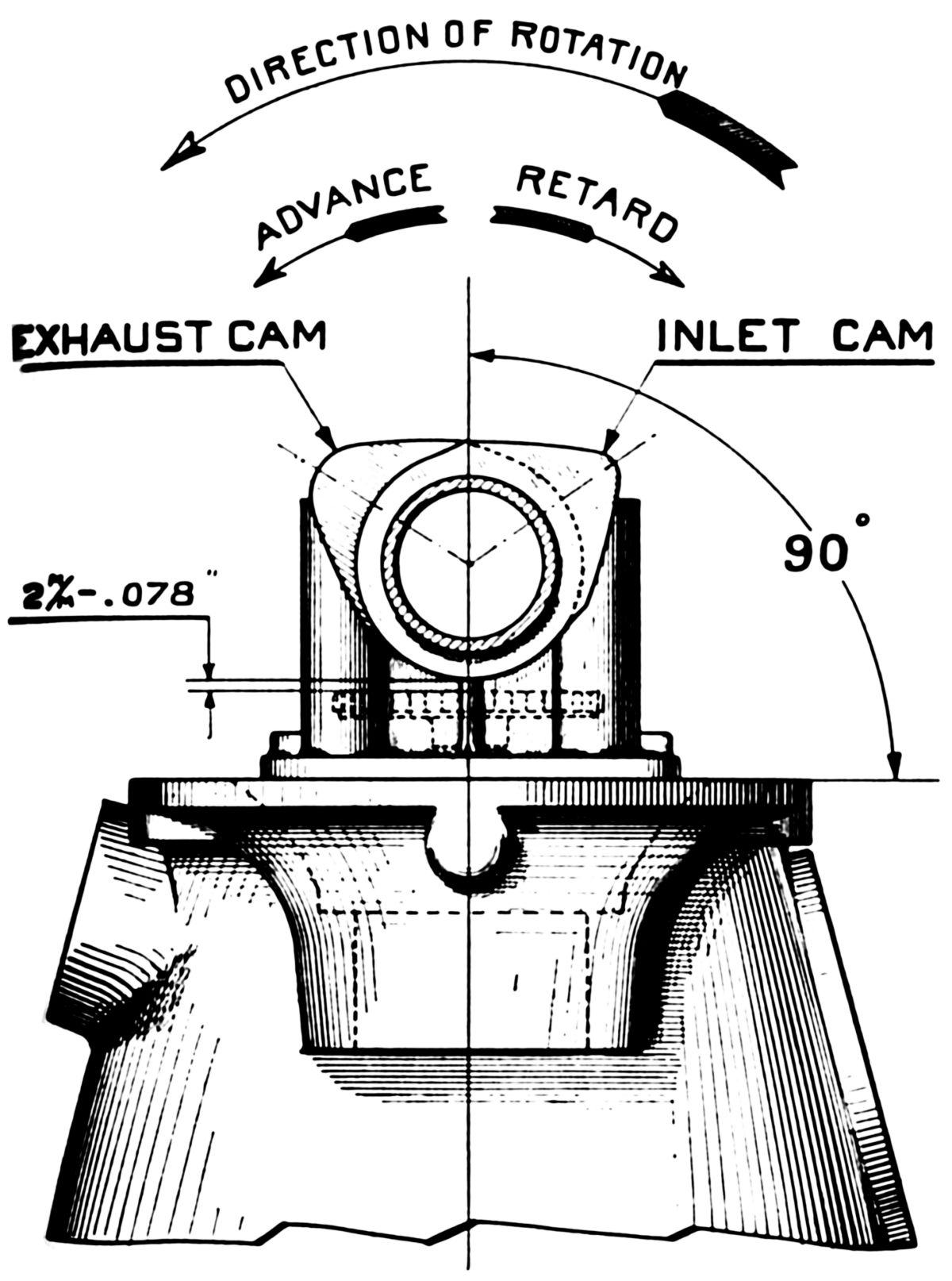
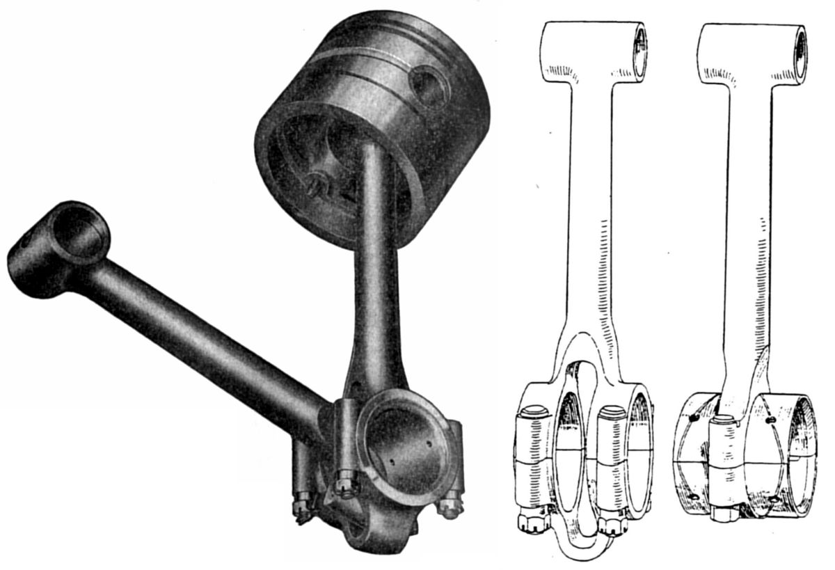
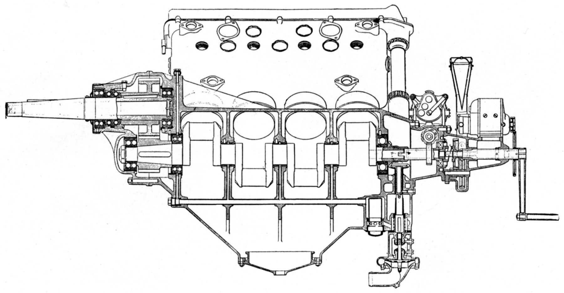
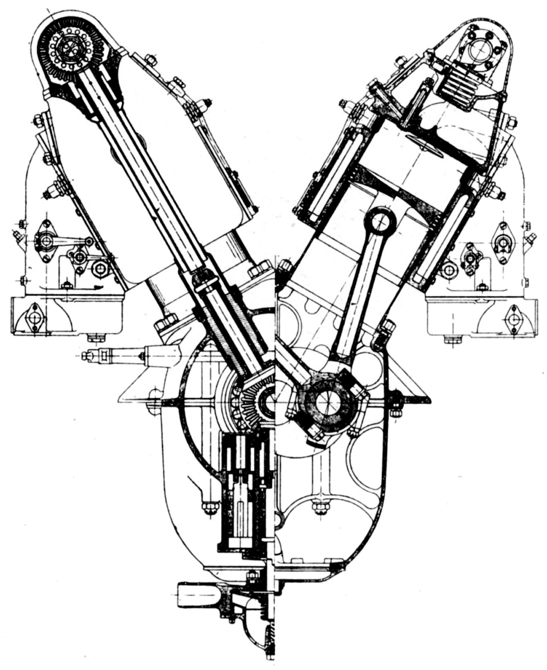
| Hispano-Suiza Features: Monobloc, Connecting Rods, Valve, Valve Gear, Timing, Ignition | |||||
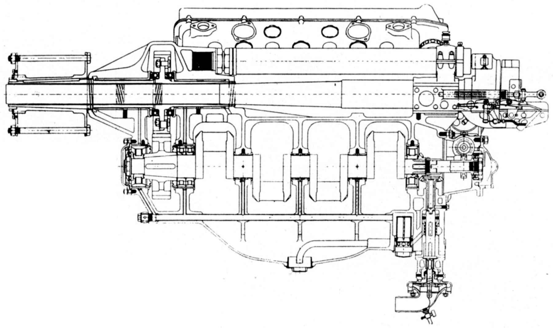
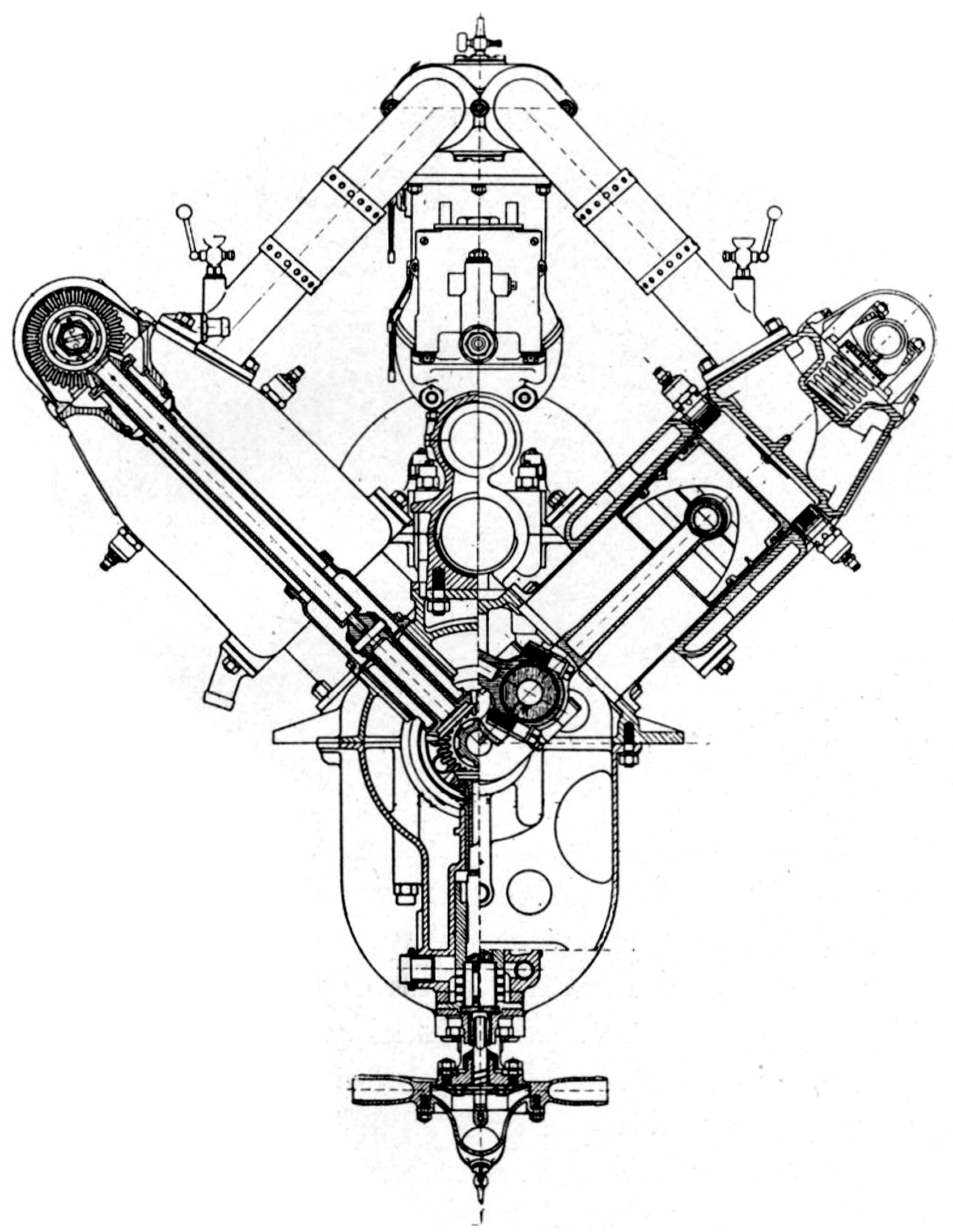
The same general construction was common to all later engine types. The cylinders were formed from a single aluminum block casting with cored water passages. Into these were screwed forged steel cylinder barrels threaded on the outside, closed at the top, and provided with a mounting flange at the bottom. Gas passages were formed in the aluminum, the valves seating upon the steel head. The assembly was coated with baked enamel both inside and out. The cast aluminum alloy pistons were fitted with four narrow compression rings placed in two grooves near the top; a lower oil-scraper ring was fitted into a relieved groove just the compression rings. The fork-and-blade connecting rods had tubular shank sections. Four bolts held the forked rod to a two-piece bronze box surrounding the crankpin. The blade-rod big-end bearing was cut into the bronze box exterior and its cap was secured by two bolts. The flat four-throw five-main-bearing crankshaft used four plain babbitt-lined bronze bearings, a single-row radial ball bearing at the timing end, and a double-row ball thrust bearing at the propeller end.
Hispano-Suiza valves had their stems parallel to the cylinder axes in the cylinder head along each block's center and were operated directly from a single overhead camshaft. The large diameter hollow valve stems had an adjustable disc at the upper end upon which a wide-faced mushroom type cam operated. This disc had a threaded boss that screwed into the valve stem; serrations on its under side matched with similar serrations on another disc that retained the two concentric helical valve springs. Adjustments were made easily by a special wrench that engaged a hole on the lower disc rim and lowered it sufficiently to disengage the upper disc serrations. Each camshaft was supported by three plain bronze bearings and driven by a vertical drive shaft and bevel gears. The valve mechanism was enclosed by an oil-tight cover.
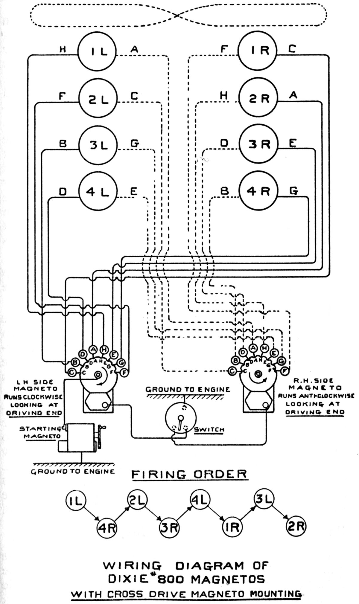
Cooling water was circulated by a centrifugal pump, and the lubricating oil by gear pumps. Dixie 800 magnetos supplied dual ignition on American-built engines, and duplex carburetors within the Vee supplied the mixture.
Among the U.S.A.-produced models , the Models A and E were built in the largest quantities. These engines were used principally for Government training airplanes, and the large war-surplus stock at the end of hostilities was sold to commercial operators and manufacturers. The Wright Aeronautical Corporation discontinued the manufacture of Hispano-Suiza designs about the time it began developing air-cooled radials.
 |
| Model A Piston, Rods |
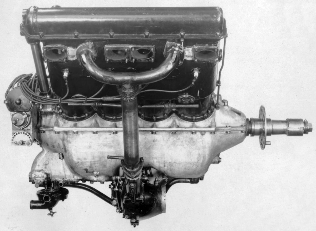
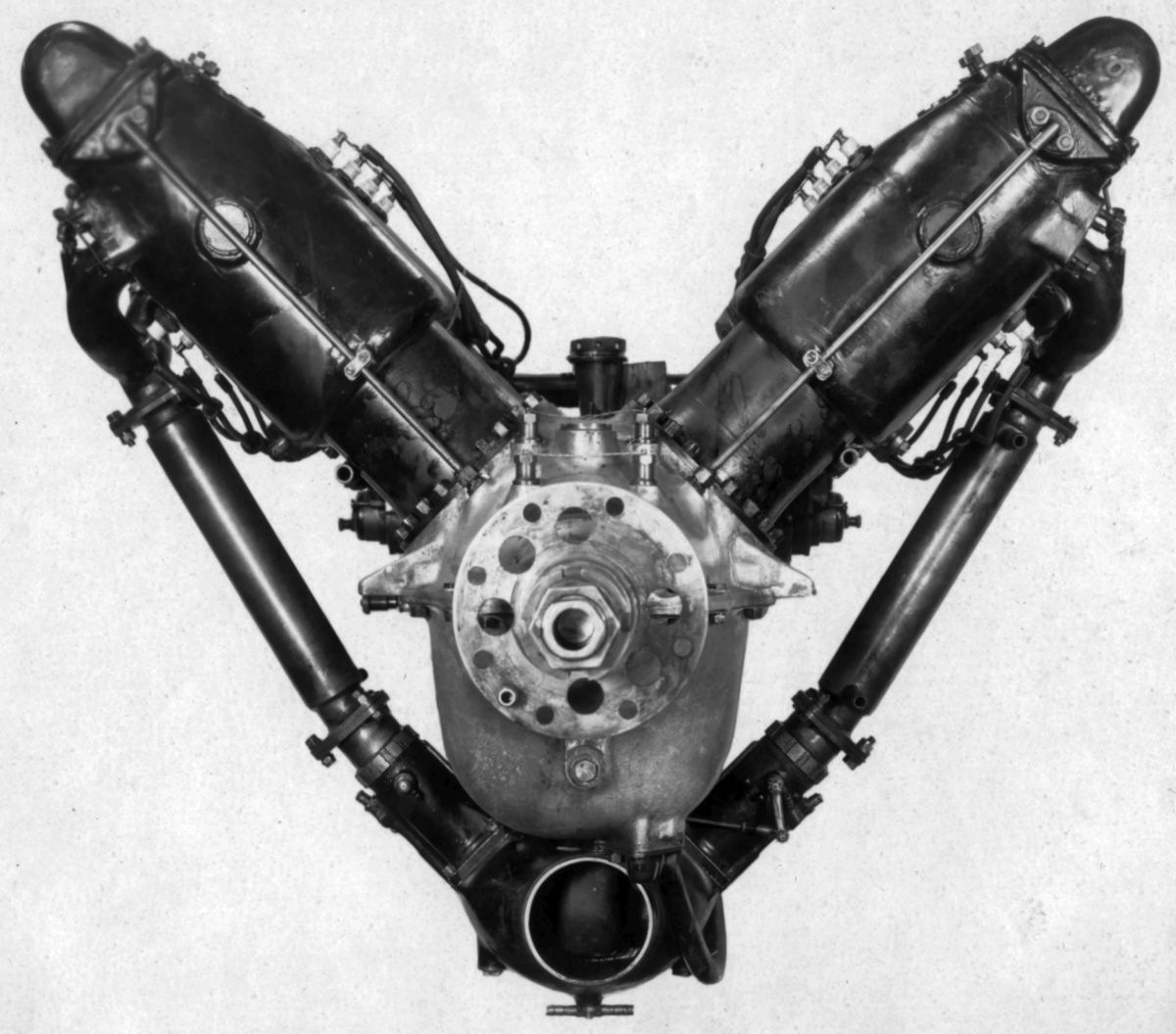
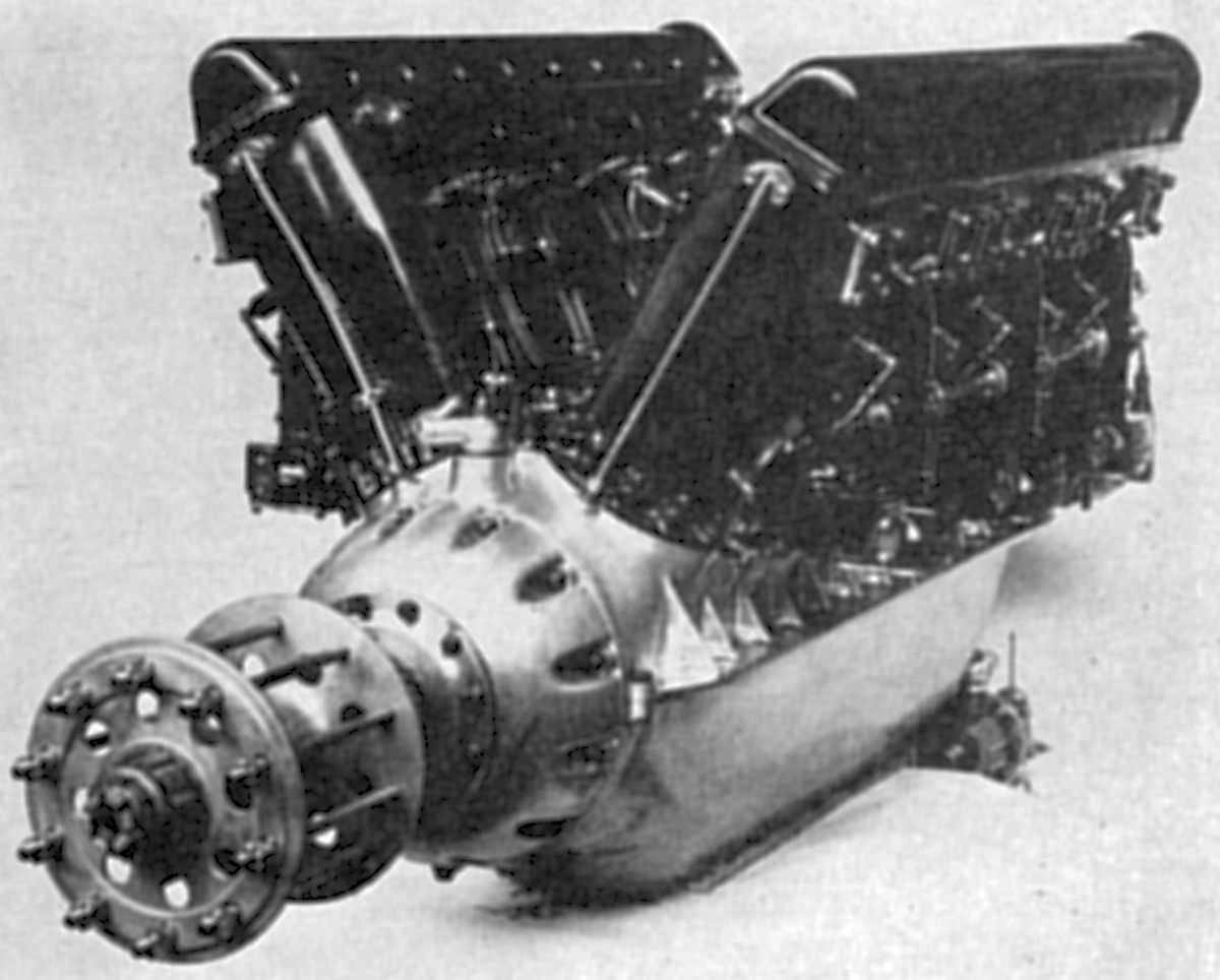
The Model A, the first Hispano-Suiza, was a water-cooled 90° V-8 with a 120 mm (4.724") bore, 130 mm (5.118") stroke, 11.762 l (717.76 in³) displacement and 4.72:1 compression ratio, that was .rated 150 hp at 1,450 rpm. Fuel consumption was 0.55 lb/hp/hr, and oil consumption was 0.039 lb/hp/hr. The Model A was often used without an oil radiator. The Wright-Martin-built engines were fitted with Stromberg NA-D4, or Twin type Zenith carburetors. The valve clear diameter was 50 mm (1.968"), and the lift 10 mm (0.394"). The inlet valves opened 10° late and closed 50° late; the exhaust valves opened 45° early and closed 10° late. The Model A was 56.69" long (including propeller hub and starting crank), 33.438" wide and 32.75" high. Dry weight was 445 lb, or 2.96 lb/hp. The magnetos were mounted in the cylinder planes on upper-crankcase extensions and driven by bevel gears from the cam drive shafts. The blade connecting rods held a split bronze bearing upon whose outer surface the forked rod ran. The wrist pin was locked in the piston, a practice discontinued on some of the later types.
The Model B was a water-cooled vertical four that used one Model A cylinder block. This engine was rated 75 hp at 1,450 rpm and weighed 315 lb, or 4.2 lb/hp.
The Model C, essentially a Model A operating at a higher speed and using a geared propeller drive, was rated at 200 hp. The propeller shaft in the Vee extended the entire engine length and the driving gears were located at the anti-propeller end.
 |
 |
 |
| Model D (AEE) | with Cannon | |
The Model D, also rated at 200 hp, employed propeller reduction gears at the engine's propeller end. A 37-mm semiautomatic cannon mounted in the Vee could be fired through the short hollow propeller shaft.
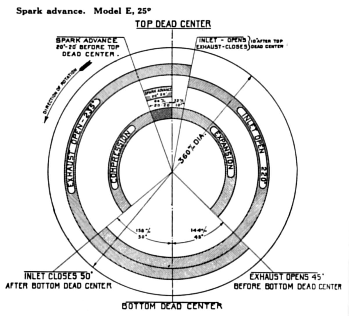
The Model E was a Model I engine operating at higher speed and with a 5.33:1 compression ratio instead of the Model I's 4.72:1. A larger carburetor supplied an increased mixture volume, and the spark advance was increased from 20° 20' to 25°. Rated at 180 hp, the Model E delivered 185 hp at 1,700 rpm, 190 hp at 1,800 rpm, and about 220 hp at 2,200 rpm. Weight was the same as the Model I, fuel consumption was 0.49 – 0.52 lb/hp/hr, and oil consumption was ≤ 0.02 lb/hp/hr.
The Model E-2, a high-compression Model E, featured several improvements including: a heavier steel cylinder head to help reduce valve troubles, more accessible magnetos located on inclined brackets at the engine rear, a triple gear-type oil pump , a front camshaft cover oil drain, a shallower lower crankcase, and camshaft timing adjustment on the vertical drive shaft.
The Model F was similar to the Model I except that no provision was made for mounting a gun in the Vee.
The Model H, frequently called the 300-hp Model, was a water-cooled 90° V-8 similar to the E and I Models. With a 140 mm (5.512") bore, 150 mm (5.906") stroke, 18.472 l (1,127.23 in³) displacement and 5.32:1 compression ratio, it developed 325 hp at 1,800 rpm and 375 hp at 2,200 rpm. Its dry weight was 632 lb, or 1.94 lb/hp. Fuel consumption was 0.521 lb/hp/hr and oil consumption was 0.055 lb/hp/hr. Inlet and exhaust valves had 56 mm (2.205") clear diameters , 13 mm (0.512") lift and 45° seats. Inlet valves opened 10° early and closed 62° late; exhaust valves opened 62.5° early and closed 29.5° late.
 |
 |
 |
 |
 |
 |
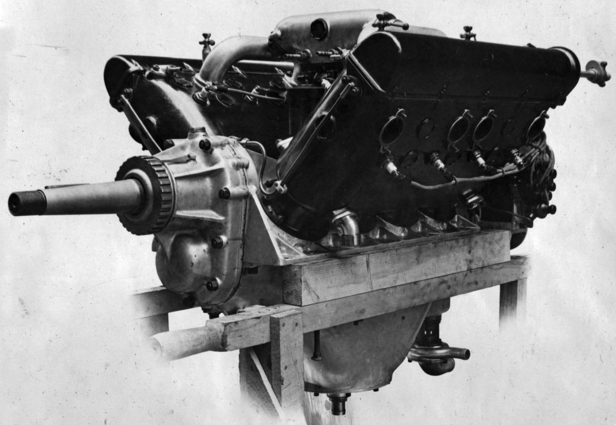
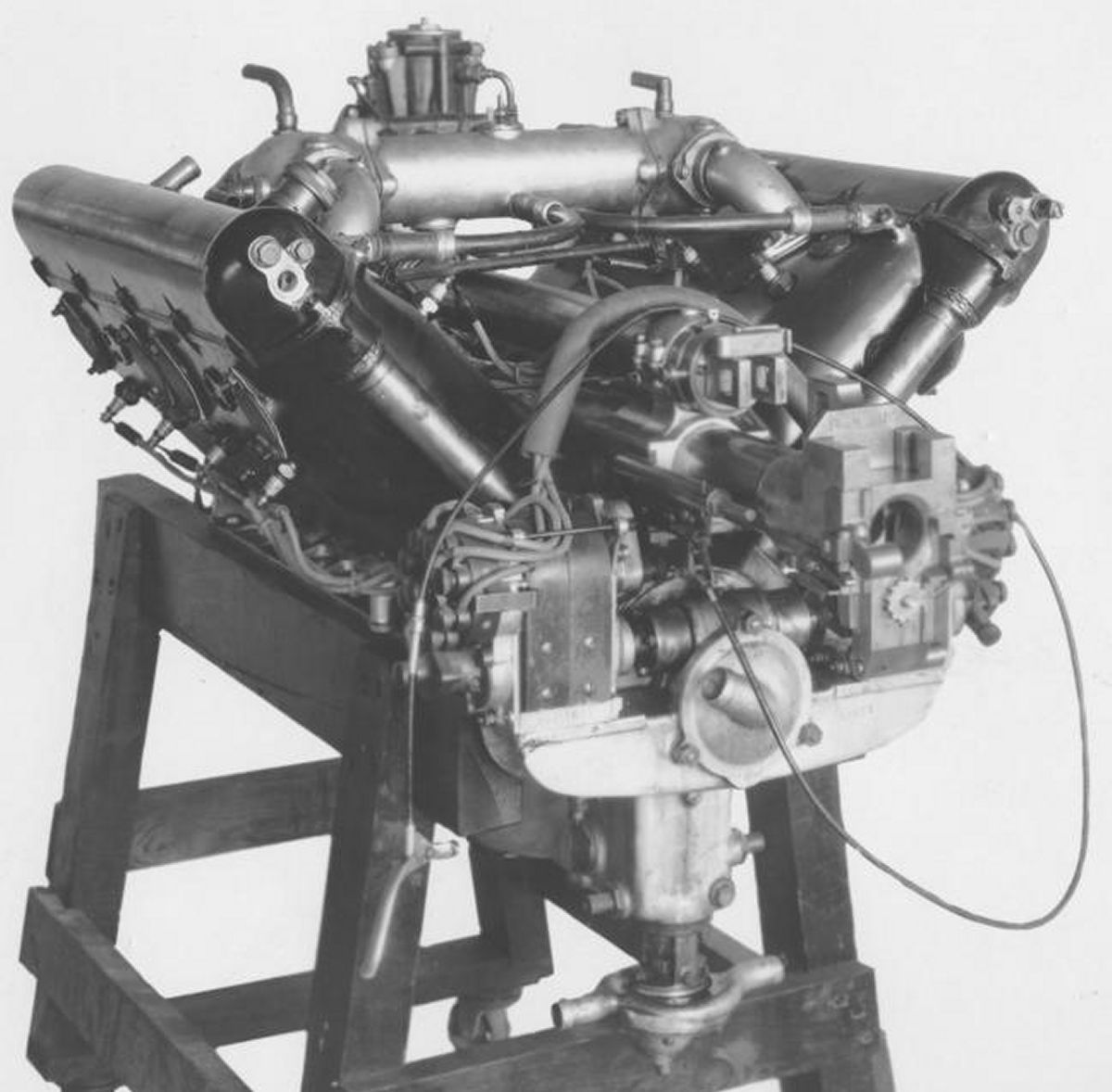
| Hispano-Suiza Model H (AEE) | with Cannon (AEE) | ||||
The Model H-2 was a Model H with minor improvements, including inclined magneto brackets replacing the cross-wise drive.
 |
 |
 |
 |
| Model H-2 with Ventral Carburetor, Cannon (NARA) | |||
 |
 |
| Models E and I (NARA |
The Model I dimensions and rated output were similar to the Model A. The magnetos were placed cross-wise, and the connecting rods were of the later Hispano-Suiza design. Weight was 470 lb, or 3.13 lb/hp.
The Model K was an experimental geared 300-hp engine designed for a 37-mm full-automatic cannon in the Vee. The two crankcase sections of the were joined along the vertical center line.
The Model K-2 featured crankcase sections joined along the horizontal centerline along with a removable propeller shaft gear housing cover was, and a triple-geared oil pump like the Model E-2.
The Model M was an experimental 300-hp engine using built-up welded-steel cylinders and a valve gear design patterned after the Liberty engine.
 |
 |
| Model 42 (NARA) | |
The Model 42 (known in the U.S. as the Model H), was the original 300-hp engine. It had a 140 mm (5.512") bore and stroke and displaced 12.931 l (789.10 in³). The stroke was later changed to 150 mm (5.906"), resulting in an 18.473 l (1,127.29 in³) displacement. The direct drive version was rated 300 hp at 1,800 rpm, and weighed 528 lb, or 1.76 lb/hp. The geared version was rated 320 hp at 2,000 rpm and weighed 605 lb, or 1.89 lb/hp.
An experimental V-16 using four Model A cylinder blocks with 120 mm (4.724") bores and 130 mm (5.118") strokes, displaced 23.524 l (1,435.52 in³) and was rated 400 hp at 2,000 rpm. The geared propeller ratio was either 1.667:1 or 1.333:1, and weight was 1,045 lb, or 2.61 lb/hp.
Another V-16 using Model 42 cylinder blocks with 140 mm (5.512") bores and 150 mm (5.906") strokes, displaced 36.945 l (2,254.52 in³), produced 600 hp at 2,000 rpm and weighed 1,210 lb, or 2.01 lb/hp. Propeller ratios were again 1.667:1 or 1.333:1.
The 8Aa was a post-WWI refined Model A that retained the same 120 mm bore and 130 mm stroke. Its compression ratio was 4.7:1, its output 155 hp at 1,500 rpm and 200 hp at 2, 000 rpm from a 418 lb weight. Fuel consumption was 0.524 lb/hp/hr and oil consumption was 0.015 lb/hp/hr.
The 8Ab, with a 5.3:1 compression ratio, produced 208 hp at 1,800 rpm, and the 248 hp at 2,240 rpm. Weight was 422.5 lb, fuel consumption was 0.537 lb/hp/hr and oil consumption was 0.026 lb/hp/hr. This was also known as the 180-hp type.
The Model 42M was a water-cooled 90° V-8 with a 140 mm (5.513") bore, 150 mm (5.906") stroke, 18.472 l (1127.23 in³) displacement and 4.7:1 compression ratio. It produced 292 hp at 1,700 rpm, 313 hp at 1,950 rpm and weighed 605 lb. Fuel consumption was 0.524 lb/hp/hr, and oil consumption was 0.028 lb/hp/hr. This engine also was referred to as 8Fg, or the 275-hp model.
The 8Fb, or 300-hp model, had the same dimensions and weight as the Model 42M, but used a 5.3:1 compression ratio to produce 320 hp at 1,800 rpm and 337 hp at 2,100 rpm. Fuel consumption was 0.528 lb/hp/hr and oil consumption was 0.033 lb/hp/hr.
The 8Fe, with a 5.5:1 compression ratio, produced 343 hp at 1,870 rpm and 352 hp at 2,100 rpm. Fuel consumption was 0.435 lb/hp/hr and oil consumption was 0.033 lb/hp/hr.
 |
| Model 50 (AEE) |
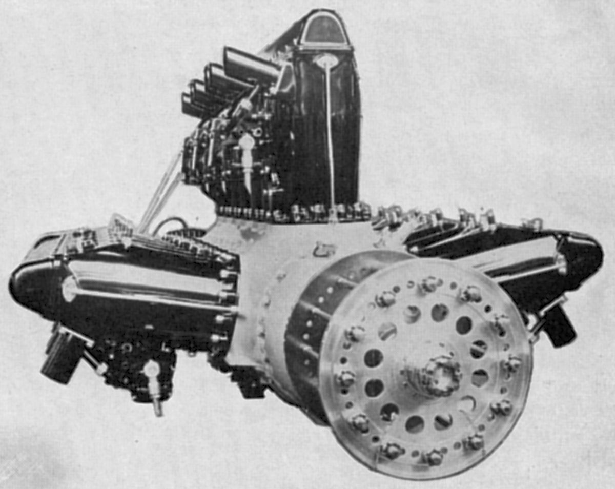
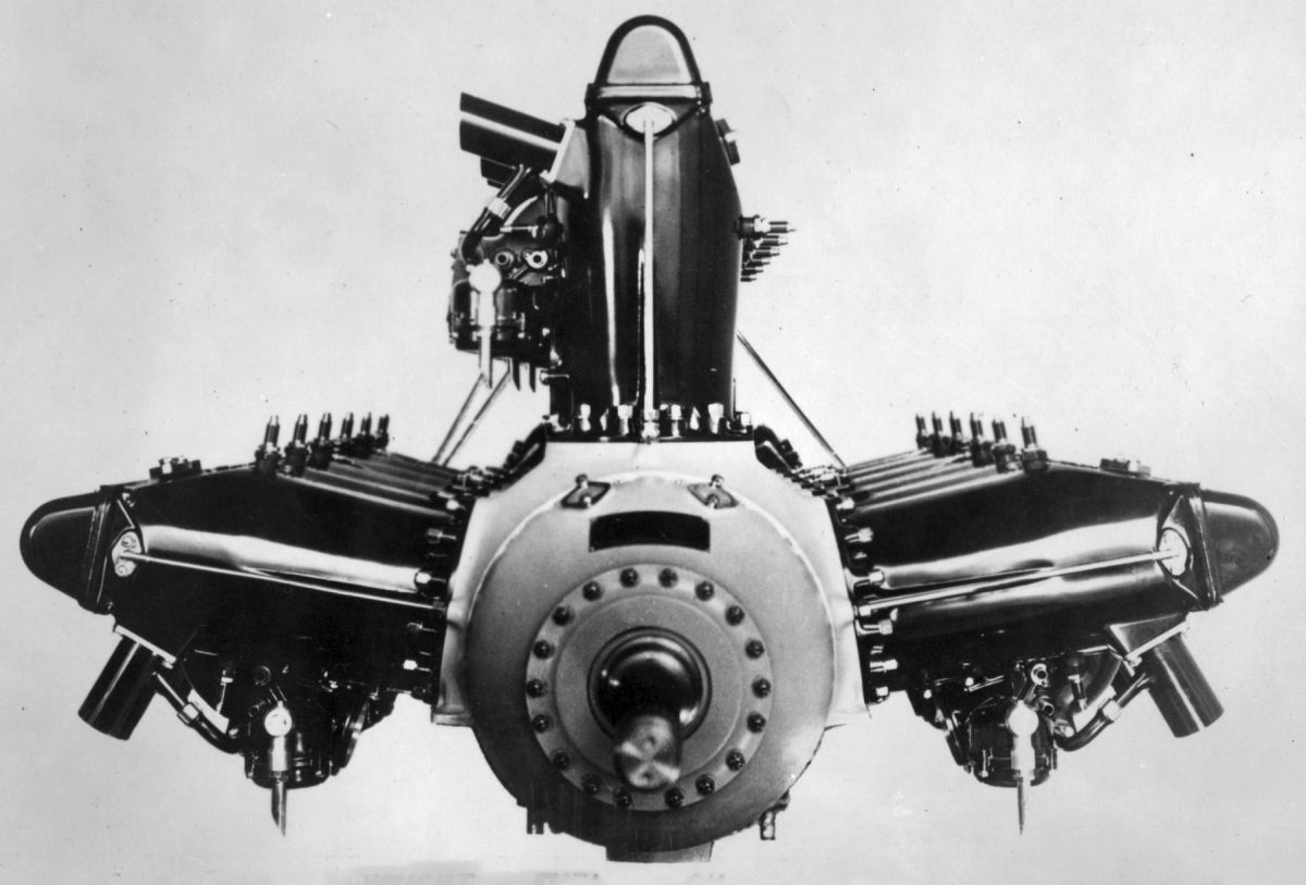
The Model 50 or 12G, a water-cooled 60° W-12, used cylinder banks similar to the Model 42. It had a 140 mm (5.512") bore, 150 mm (5.906") stroke and 27.709 l (1690.91 in³) displacement. The W-12s used a straight manifold with a special Zenith horizontal carburetor mounted at its rear to serve each cylinder bank. Dry weight was 860 lb.
The 12Ga, or 450-hp type, with a 5.3:1compression ratio, produced 497 hp at 1,800 rpm and 518 hp at 2,000 rpm. Fuel consumption was 0.493 lb/hp/hr and oil consumption was 0.011 lb/hp/hr.
The 12Gb, or 500-hp type, introduced in 1925, employed a 6.2:1 compression ratio, and delivered 590 hp at 2,000 rpm. Fuel and oil consumptions were 0.499 and and 0.014 lb/hp/hr, respectively.
 |
 |
| Model 51 (AEE) |
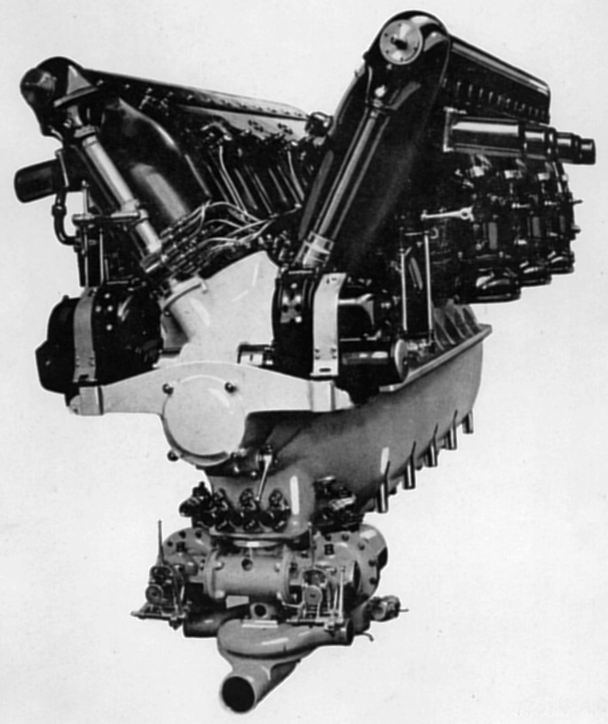
The Model 51 , a water-cooled 60° V-12, had a 140 mm (5.512") bore, 150 mm (5.906") stroke and 27.709 l (1690.91 in³) displacement. It weighed 898 lb dry, including the propeller hub. This engine had both inlet and exhaust on its exterior. A combined inlet port served adjacent cylinder pairs, resulting in three carburetors per bank. These carburetors were completely enclosed and fitted with permanent inlet pipes that extended to the crankcase bottom where air was drawn through the oil cooler attached to the crankcase.
The 12Ha, or 450-hp type, with its 5.3:1 compression ratio, delivered 613 hp at 2,000 rpm. Fuel consumption was 0.517 lb/hp/hr and oil consumption was 0.019 lb/hp/hr.
The 12Hbr was a 12Hb engine fitted with 2:1 propeller reduction gears. It weighed 1,012 lb and delivered 590 hp at 2,100 rpm.
The Model 52 was a water-cooled 60° V-12 with a 120 mm (4.723") bore, 150 mm (5.906") stroke and 20.358 l (1,242.32 in³) displacement weighing 759 lb.
The 12Ja, or 350-hp model, with a 5.3:1 compression ratio, produced 379 hp at 1,800 rpm and 444 hp at 2,300 rpm. Fuel consumption was 0.508 lb/hp/hr and oil consumption was 0.014 lb/hp/hr.
The 12Jb, or 400-hp model, introduced in 1929 with a 6.2:1 compression ratio, produced 444 hp at 2,000 rpm and 480 hp at 2,300 rpm. Fuel consumption was 0.504 lb/hp/hr and oil consumption was 0.019 lb/hp/hr.
The 12Kb, or 600-hp model, engine was a water-cooled 60° W-12 with a 140 mm (5.512") bore, 170 mm (6.693") stroke, 31.403 l (1,916.33 in³) displacement and 6:1 compression ratio weighing 913 lb. It produced 635 hp at 2,100 rpm. Fuel and oil consumptions were 0.484 and 0.019 lb/hp/hr.
The 12Lb had the same bore and stroke as the 12Kb, but was a 60° V-12 that delivered 660 hp at 2,100 rpm and weighed 946 lb. The fuel and oil consumptions were the same as the 12Kb.
The 12Lbr was a 12Lb fitted with a 2:1 propeller reduction gear. It produced 640 hp at 2,100 rpm, weighed 1045 lb, and had a 0.495 lb/hp/hr fuel consumption.
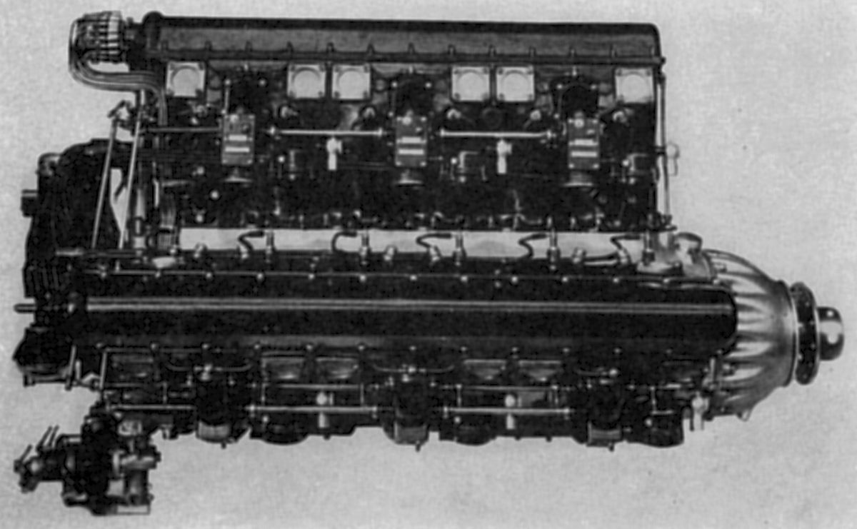
The 6Pa, or 100-hp engine, a water-cooled vertical six introduced in 1928, had a 110 mm (4.331") bore, 140 mm (5.512") stroke, 7.983 l (487.15 in³) displacement and 5.5:1 compression ratio. Weighing 396 lb, it produced 150 hp at 2,100 rpm, had a 0.484 lb/hp/hr fuel consumption and a 0.011 lb/hp/hr oil consumption.
The 6Mb, or 250-hp engine, a larger vertical six, had a 130 mm (5.118") bore, 170 mm (6.693") stroke, 13.539 l (826.20 in³) displacement and 6:1 compression ratio. It delivered 300 hp at 2,100 rpm, weighed 550 lb, and had fuel and oil consumptions of 0.484 and 0.011 lb/hp/hr, respectively.
The 6Mbr, with a 2:1 propeller reduction gear, produced 290 hp at 2,100 rpm and weighed 638 lb.
The 12Mb, a water-cooled 60° V-12 with cylinder banks similar to the 6Mb, displaced 27.077 l (1,652.34 in³), had a 7:1 compression ratio, and weighed 880 lb. It delivered 580 hp at 2,100 rpm and it consumed 0.484 lb/hp/hr fuel and 0.015 lb/hp/hr oil.
The 12Mc employed a 7:1 compression ratio, and the 12Md had a 6.2:1 compression ratio. When fitted with 2:1 propeller reduction gears the 12Mb engine was known as the 12Mbr, had a 570 hp at 2,100 rpm output and weighed 979 lb. Fuel and oil consumptions were 0.495 and 0.015 lb/hp/hr.
 |
 |
| 12Nb (AEE) | |
The 12NbA, a water-cooled 60° V-12 with a 150 mm (5.906") bore, 170 mm (6.693") stroke, 36.05 l (2199.91 in³) displacement and 6:1 compression ratio, delivered 760 hp at 2,100 rpm, and weighed 1,001 lb. Fuel and oil consumptions were 0.484 and 0.017 lb/hp/hr.
The 12Nbr, a geared companion to the 12NbA with a 2:1 reduction gear ratio, delivered 740 hp at 2,100 rpm and weighed 1,100 lb. Fuel and oil consumption were 0.495 and 0.017 lb/hp/hr.
 |
 |
 |
| 18Sbr (AEE, NARA) | ||
The 18Sbr was a water-cooled W-18 that Hispano-Suiza built for the 1929 Schneider Cup Races. It used 12Nb cylinder banks, meaning it had a 150 mm (5.906") bore, 170 mm (6.693") stroke and 64.075 l (3,299.86 in³) displacement The racing engine had a 10:1 compression ratio while the stock engine had a 6.2:1 compression ratio. The three cylinder banks had 80° angles between the center and outer banks. The racing engine with its 10:1 compression ratio was rated 1,650 hp at 2,400 rpm. A stock engine that was marketed later had a 6.2:1 compression ratio and was rated 1,000 hp at 2,000 rpm. Dry weight of both engines, including the propeller hub, was 1,188 lb.
Four Elektron castings comprised the crankcase upper and lower sections and the two end covers. The half-cylindrical upper section was milled flat parallel to the horizontal centerline, forming engine supports below the outer cylinder banks. The massive separate caps for the six plain main journal bearings were dove-tailed and held to the crankcase upper section by four long studs and four short studs; the transverse component was addressed by two inclined screws. The forward crankcase end was heavily ribbed to support the Farman type reduction gear housing. The five most-forward crankshaft main bearings were thin steel shells lined with white metal; the aft bearing was a roller bearing. Air circulated through the seven crankcase box girders to cool the bearings and permit higher bearing loads. The lower crankcase cover sloped from its center toward each end, where oil collected and was removed by two scavenging pumps. These, along with the oil pressure pump, were vane-type pumps. A fuel pump was located underneath the oil pumps. The crankshaft had disk-shaped crank checks that were beveled opposite the crankpins. The large diameter journals had large bored holes, and a thin steel tube of slightly less diameter was held in the journal hole by ring nuts at each end. The small space between the tube and the bored journal hole carried oil that reached the crankpin bearing via a light metal tube. The H-shank section master rod had a tube clipped to it that supplied piston pin lubrication. The master rod big end hearing was a white-metal-lined steel bushing. The cap, provided with four ribs, was held to the master rod by an unusual type of hinge joint whose pins were parallel to the crankpin, carrying the loads in shear. Hispano-Suiza claimed this to be a lighter, more rigid, and more accurate than the usual bolted caps. The tubular-shank link rods had bronze bushings pressed into the bosses at each end. The first engine did not include a supercharger, but that addition was planned for later models. A carburetor for each cylinder pair was employed on the racing engine.
Hispano-Suiza continued designing and building engines into the 1950s. Some were licensed for production in other countries, others had features appropriated by engine designers worldwide. Among these were the 12Y V-12 series, introduced in 1932. The Soviet Union produced the Klimov M-100, a licensed 12Y, which led to the Klimov VK-105 series that powered Yakovlev and Lavochkin fighters. Czechoslovakia licensed the 12Y and produced it as the Avia HS 12Ydrs; Switzerland produced the HS-77, another licensed 12Y.
References
Angle, Glenn D, ed. Aerosphere 1939 (New York, New York: Aircraft Publications, 1940).
Anble, Glenn D, ed. Airplane Engine Encyclopedia (Dayton, Ohio: Otterbein Press, 1921).
Bradford, Francis H. and Ric A. Dias Hall-Scott: The Untold Story of a Great American Engine Maker (Warrendale, PA: SAE, 2007).
Spike Hall-Scott Power: Technical & Photo Book (Little Rock, AR: 2022)
Image Sources: A39 = Aerosphere 1939; AEE = Airplane Engine Encyclopedia; Flt = Flight Magazine; NARA = U.S. National Archives and Records Administration; REL = Richard E. Loftis; UKNA = United Kingdom National Archives.
Send mail to
![]() with questions or comments about this web site.
with questions or comments about this web site.
![]()