Selected Early Engines
Elbridge, Engineering Division, E.N.V.
Compiled by Kimble D. McCutcheon
Published 11 May 2022; Revised 19 May 2022
|
|
|
| Three-Cylinder (AEE) | Six-Cylinder (AEE) | Aero Special (AEE) |
Elbridge
In 1908, the Elbridge Engine Company of Rochester, New York marketed water-cooled two-stroke in-line marine engines whose dependability and low specific weight interested amateur aviators. Numerous successful amateur flights during 1909-1911 were powered by Elbridge engines.
The Type A, a water-cooled two-cylinder with a 3.75" bore, 3.50" stroke and 77.3 in³ displacement produced 6 – 10 hp and weighed 88 lb.
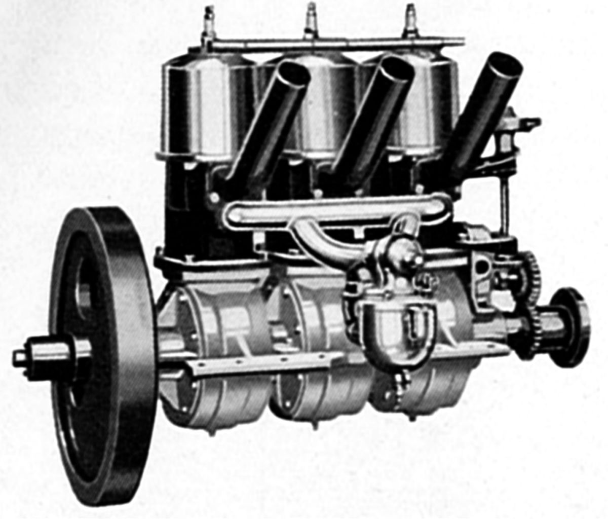
The Type C, a water-cooled three-cylinder with a 4.625" bore, 4.50" stroke and 226.8 in³ displacement was rated 18 – 30 hp and weighed 235 lb.
The Featherweight water-cooled series was first marketed during Spring 1910 in three, four, and six-cylinder versions. These had 4.625" bores 4.500" strokes. The cylinders were cast from iron, and the crankcase from aluminum. Bosch magnetos supplied ignition, Schebler carburetors furnished the mixture, and a splash lubrication system was employed.
The Featherweight three-cylinder, displacing 226.8 in³, was rated 30 – 45 hp. at 1,400 rpm, and weighed 150 lb. It was 32" long, 12.5" wide, and 20.25" high.
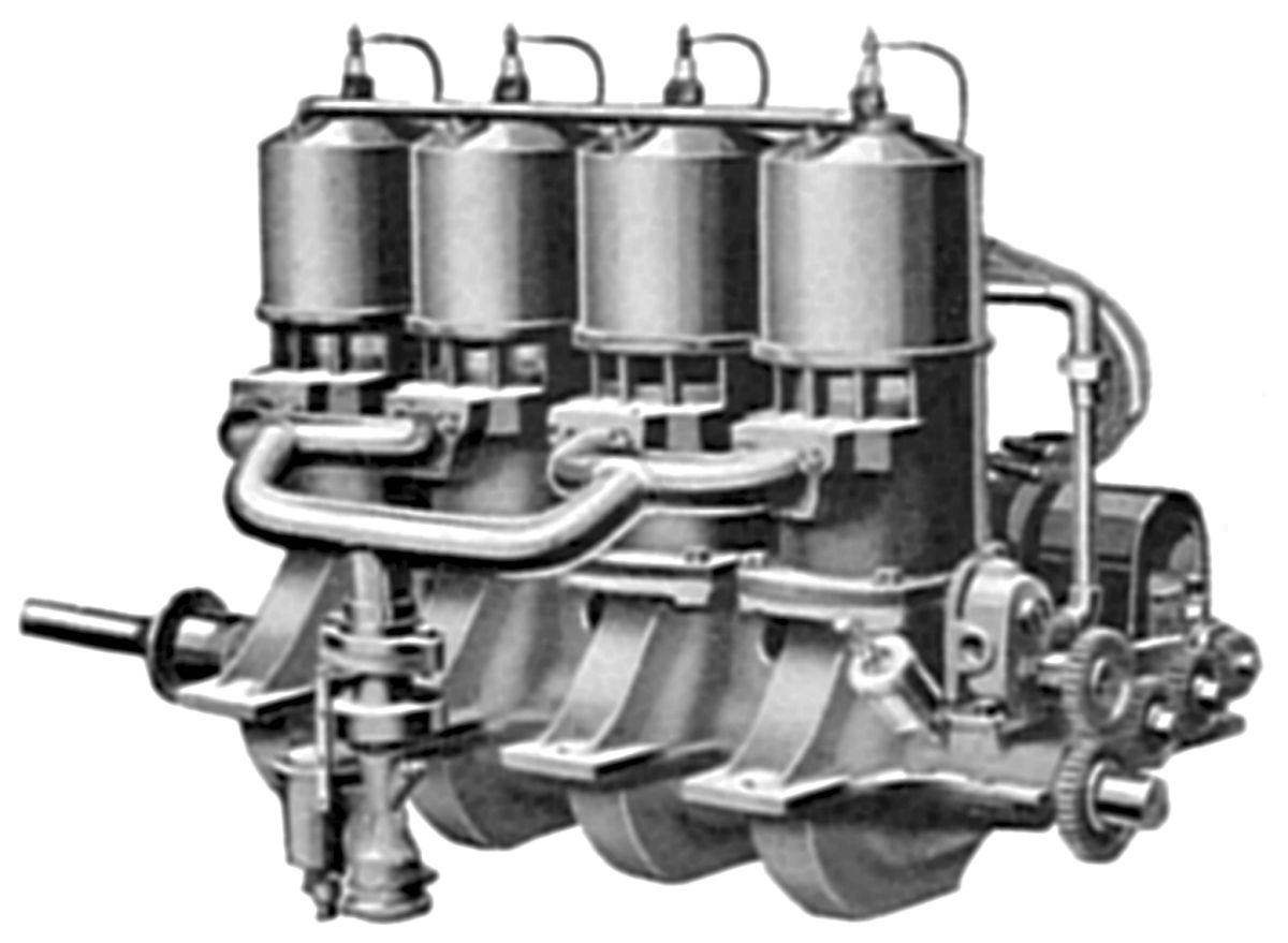
The Featherweight four-cylinder, displacing 302.4 in³, was rated 40 – 60 hp at 1,400 rpm and weighed 200 lb. It was 38" long, 12.5" wide, and 20.25" high.
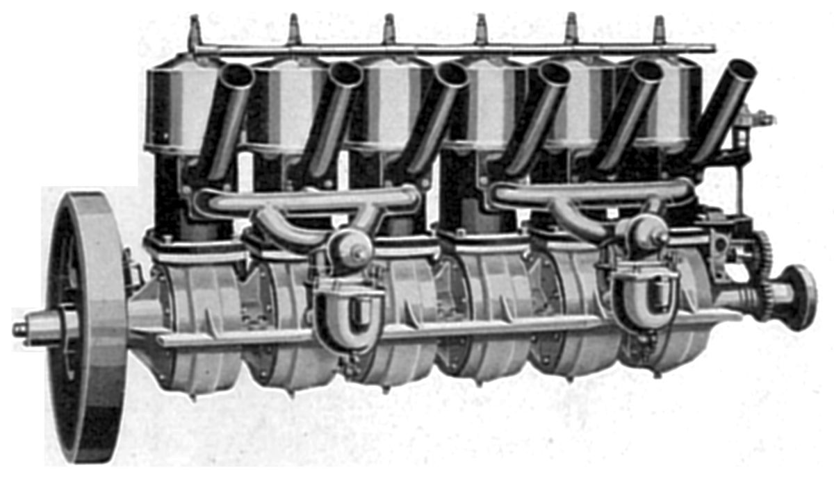
The Featherweight six-cylinder, displacing 453.6 in³, was rated at 60 – 80 hp at 1,400 rpm and weighed 250 lb. It was 50" long, 12.5" wide, and 20.25" high.
The Elbridge Aero Special, a modified four-cylinder Featherweight, was introduced in 1911 with a 50 – 60 hp rated output; it weighed 150 lb, less ignition. This engine was more efficient at higher speeds up to 2,000 rpm.
Engineering Division
No U.S. organizations played bigger early engine development roles than the U.S. Army Air Service Engineering Division at McCook Field, Dayton, Ohio and the U.S. Navy Bureau of Aeronautics at the Washington Navy Yard, Washington, DC. These two organizations oversaw a golden age in engine development that paved the way for aviation's future. The U.S. military had been caught unprepared for WWI. As a result, most U.S. built engines were licensed copies of foreign designs. Only the 90 hp Curtiss OX-5 and 400 hp Liberty V-12 designs were indigenous. The OX-5 was already obsolete by WWI's end and the Liberty 12 was not powerful enough for the aircraft designs the military envisioned. The U.S. Congress, also realizing the need for more engine research and development, appropriated money to fund the endeavors. Unfortunately, like most things from the U.S. Congress, the funding was cut short before its full impact was realized. Still, the period from 1920 to 1925 was rich with engine innovation, and while all projects were not successful, the failures marked avenues down which future engineers should not tread.
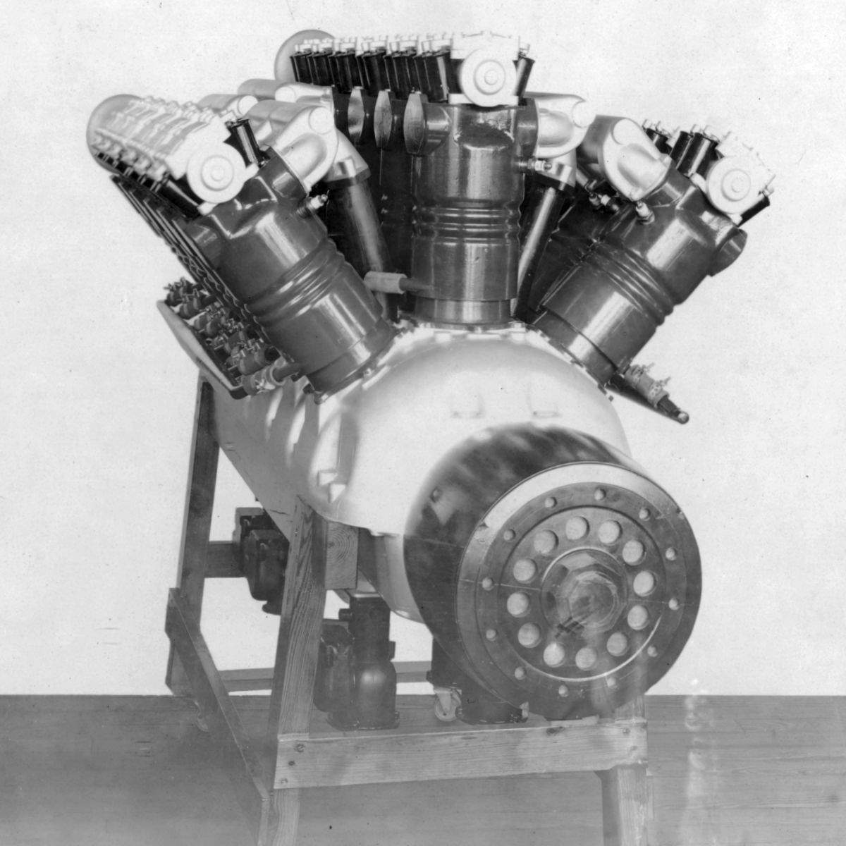
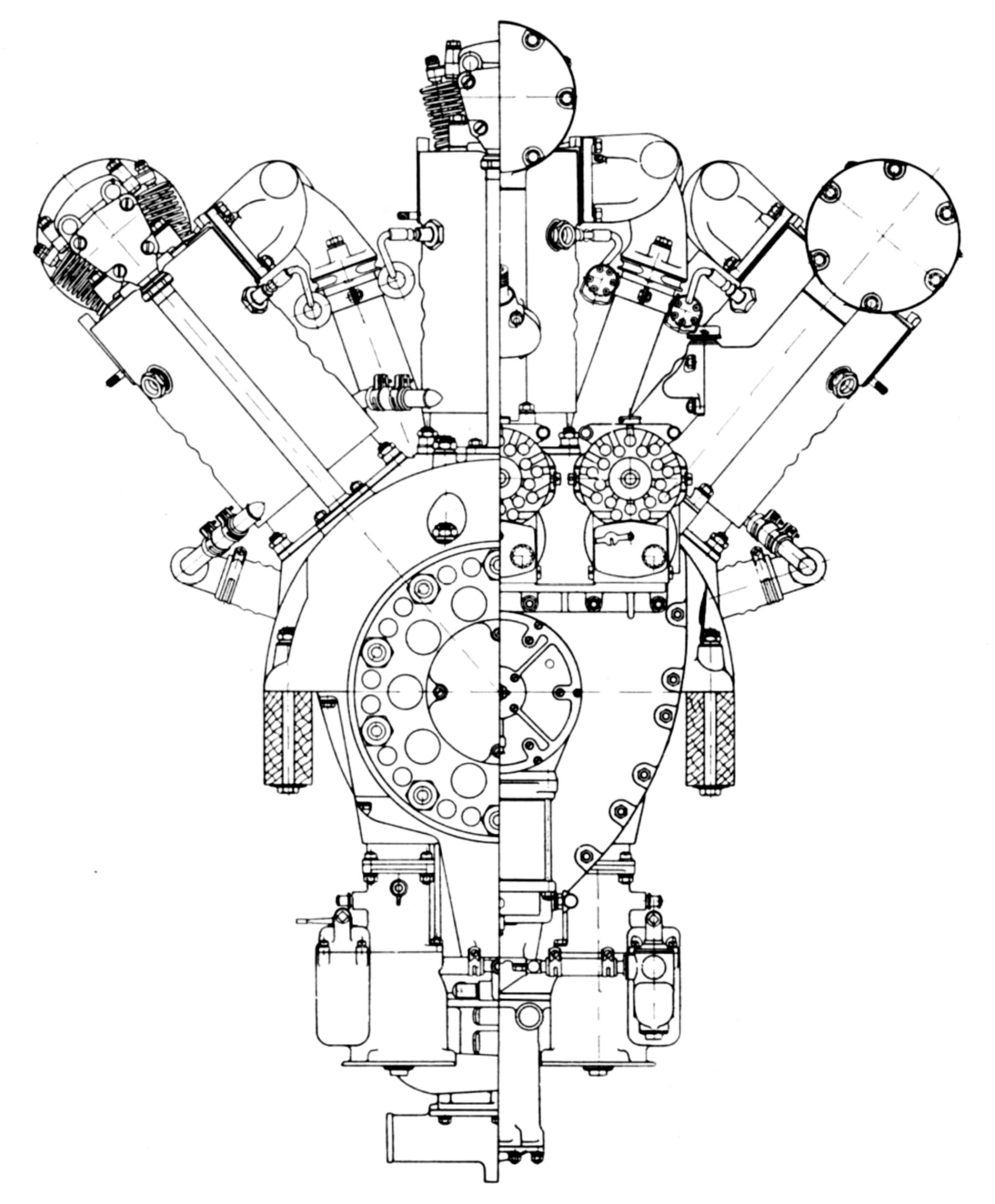
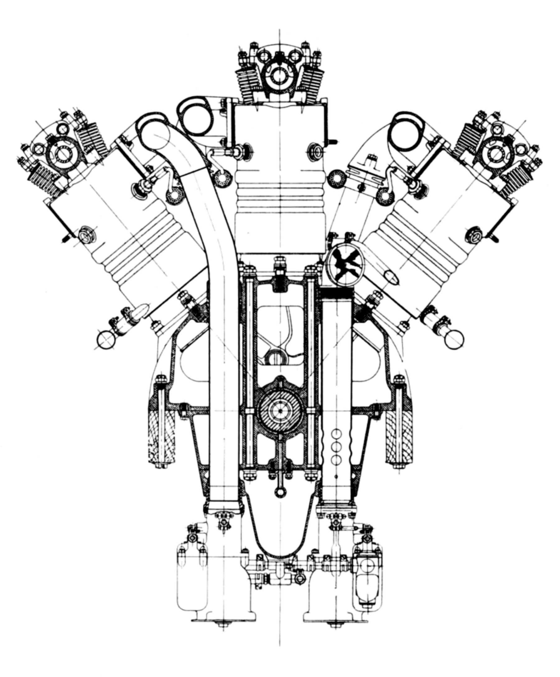
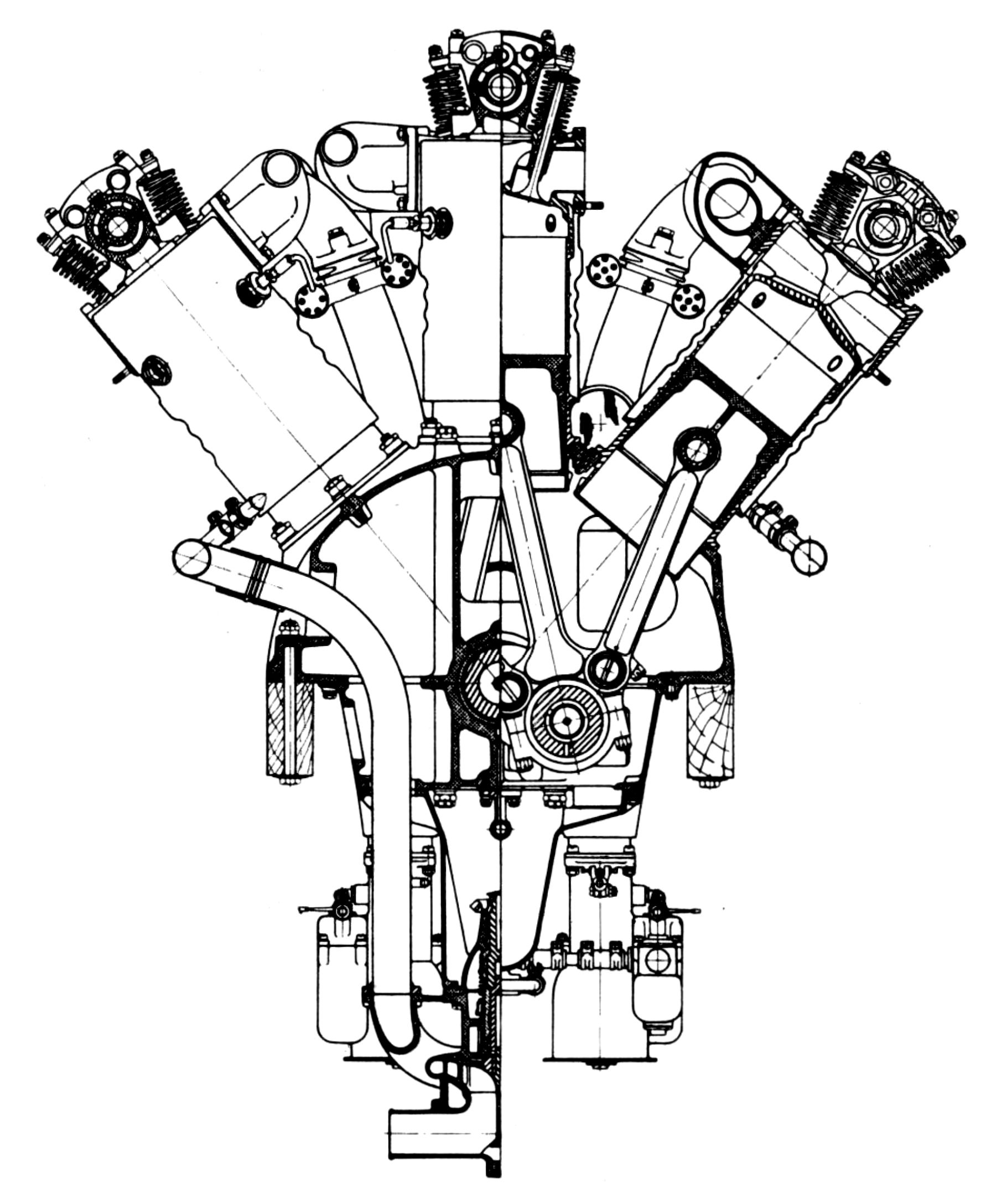
Both the Army and Navy were instrumental in air-cooled radial engine development, but the Navy's decision to stop using water-cooled engines in its aircraft really helped the radial engine to mature. Meanwhile, the Army Air Service Engineering Division, keen on higher-powered water-cooled engines for pursuit aircraft, tried developing engines of its own design and encouraged existing manufacturers to produce new designs. The Air Service had examined higher-powered foreign engines, such as the Napier Lion and Lorriane-Dietrich Type 15. Engine Division personnel became enamored with W-type engines with three cylinder banks as this layout could produce high power with minimal frontal area (aerodynamic drag). One such project was the Engineering Division Model W-1 and its successors.
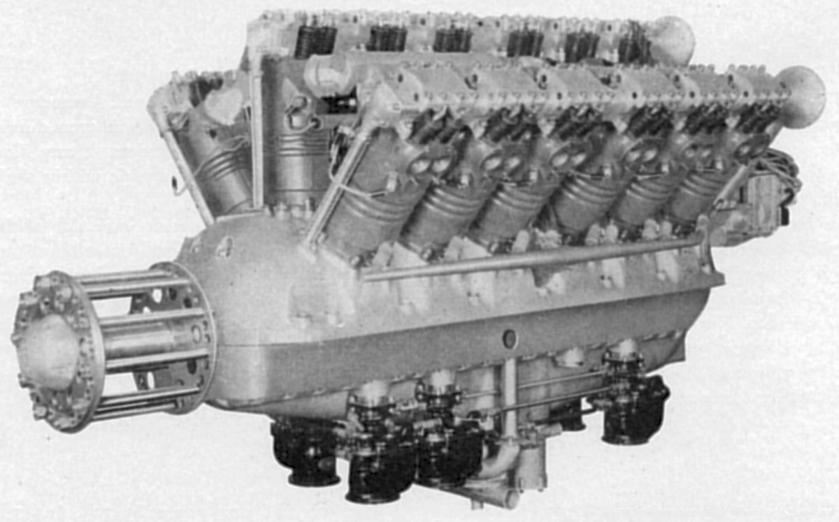
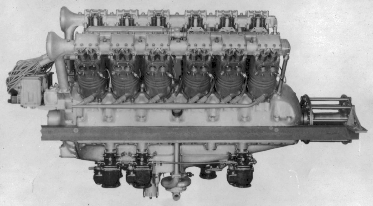
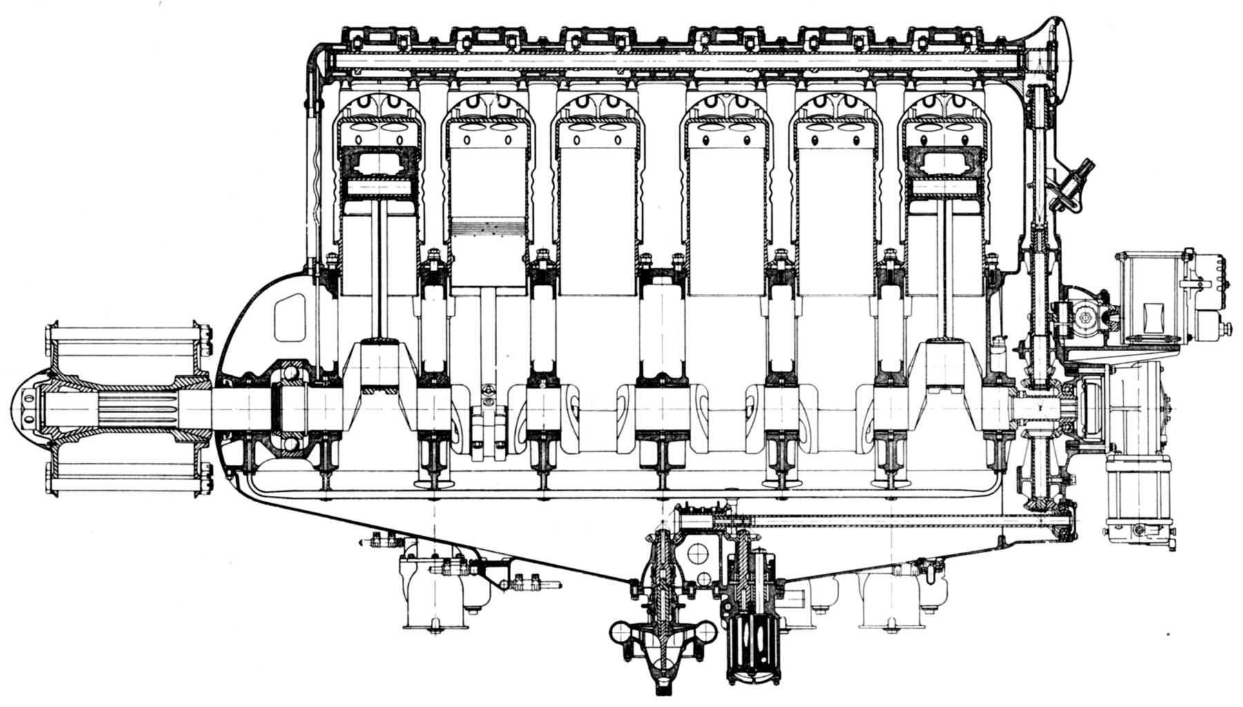
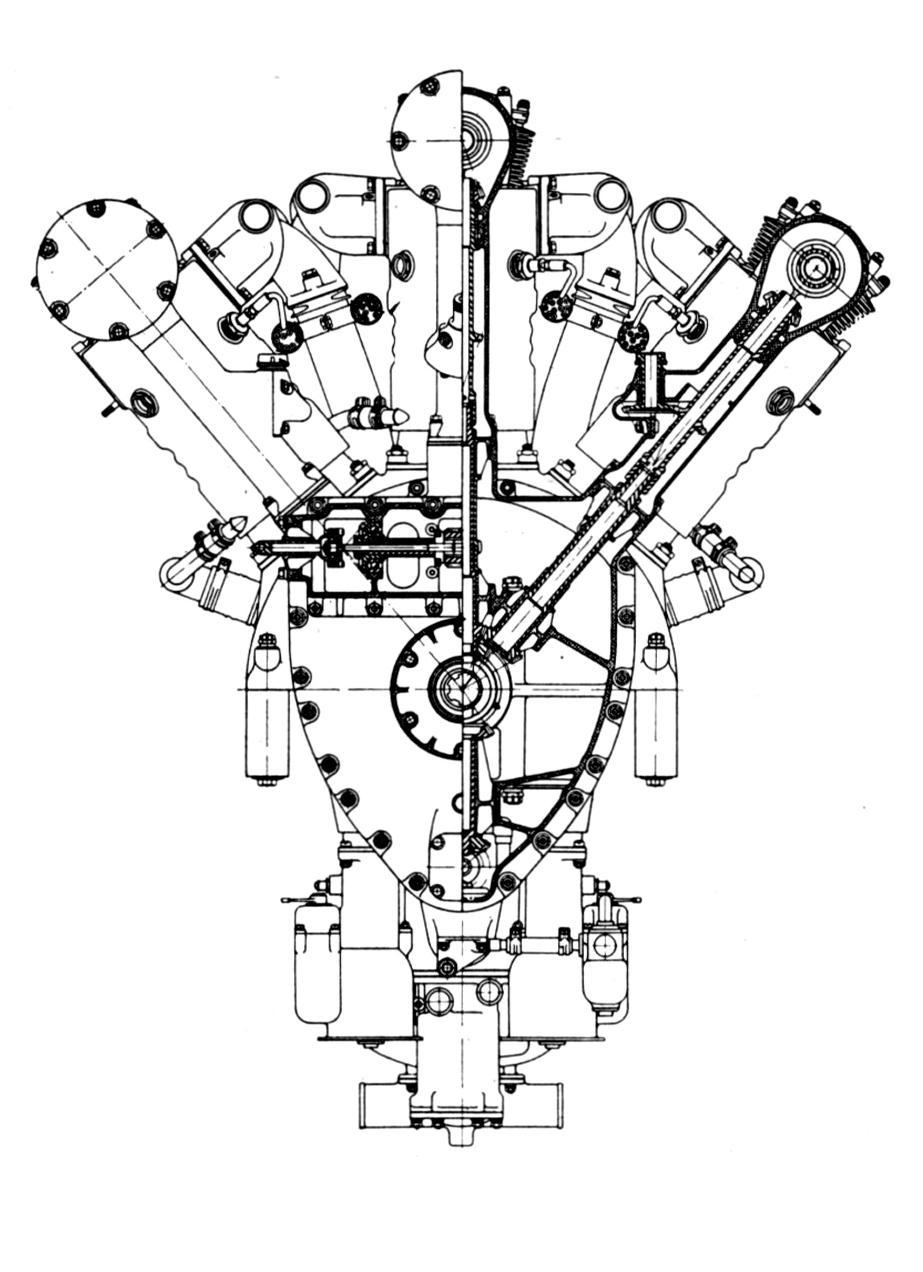
The Model W-1, started in 1919 and first tested in 1920, was a water-cooled W-18 with the two outer cylinder banks spaced 40° from the vertical center bank. With a 5.5" bore, 6.5" stroke, 2,779.7 in³ displacement and 5.4:1 compression ratio, the W-1 was rated 700 hp at 1,700 rpm and 750 hp at 1,800 rpm. Dry weight was 1,725 lb.
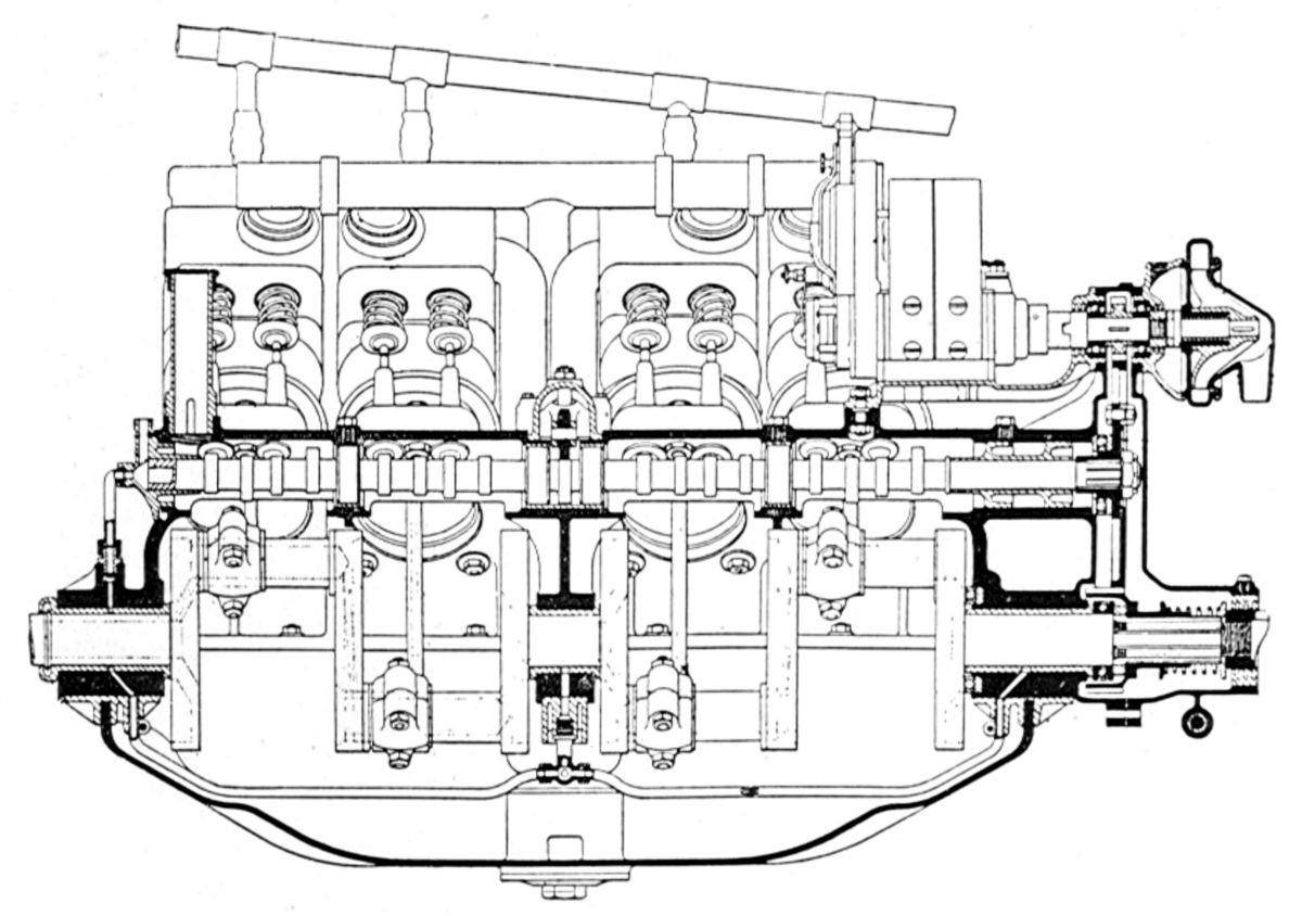
The individual built-up steel cylinders had a barrel that was screwed and welded into a forged-steel cylinder head onto which four forged-steel valve ports were welded. The sheet-steel water jackets were formed in two sections and welded in place. The inlet and exhaust valve clear diameters were 1.75". Valve lift for both inlet and exhaust valves was 0.375". The valves had 30° seats, stems inclined at 15° relative to the cylinder center lines, and were operated by forked rocker arms from an overhead camshaft with a cam for each valve pair. The single-piece camshaft housing extended over the heads of each cylinder row and was held down to each cylinder by four studs. The camshafts were driven by vertical shafts and bevel gears at their aft ends. Attached to each camshaft front housing was an oil drain pipe that also contained the camshaft oil pressure line. Valves were timed so the inlets opened 10° late and closed 40° late while the exhausts opened 50° early and closed 10° late.
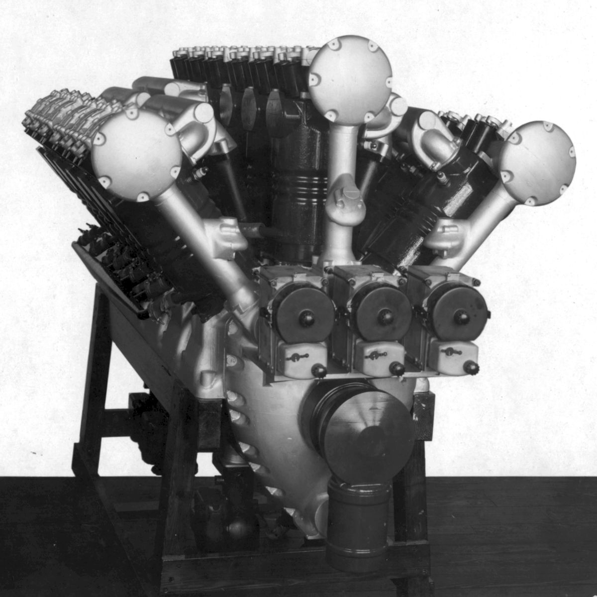
The articulated connecting rods featured a symmetrical master rods operating in the center cylinder bank. The link rod lower ends were forked and all three rods had H-section shanks. The aluminum pistons were fitted with four top rings, the lower of' which acted as an oil scraper. The six-throw crankshaft was supported in eight plain bearings, one being just outside a deep-race annular ball bearing that carried propeller thrust loads. Six Stromberg carburetors located underneath the crankcase lower half supplied the mixture by feeding into long steel induction pipes that passed through, but were not rigidly attached to, the crankcase. Flanges at the upper ends joined these pipes to water-jacketed cast aluminum inlet manifolds that fed three cylinders each. The induction pipes had packing joints at the top and bottom and were exposed to the crankcase oil splash They were arranged so that the six inlet manifolds were identical; breather tubes were inserted at the two remaining positions. To make this symmetrical arrangement possible, the center row's three rear cylinders' inlet and exhaust sides were reversed with respect to the first three cylinders. The aluminum crankcase was cast in three sections. The upper crankcase half outer wall was carried to the outside edge of the engine supports. The lower crankcase half was shallow and had the effect of individual bearing caps with the side walls tying them together. Both upper and lower halves had double transverse walls and were doweled and held together by long through bolts. The oil sump was bolted to the crankcase lower half and carried the oil and water-pump bracket. The water pump had two outlets that passed inside the engine frame members on both sides and were connected with water manifolds delivering to nine cylinders each. A gear pump delivered oil under pressure to a manifold bolted underneath to the lower crankcase half. The camshaft and accessory drives were contained in a gear case bolted over the three crankcase sections at the rear end. Provision was made for driving four eighteen-cylinder Splitdorf magnetos, each one firing one of the four plugs in each cylinder. A Bijur electric starter was mounted on the gear case and engaged with the floating accessory drive gear. The oil and water pumps were driven by a horizontal shaft in the oil pan. An electric generator was driven from this shaft's rear end, and at right angles and just below was a gear-type gasoline pump.
The Model W-2 was a larger water-cooled W-18 with little resemblance to the W-1 that was designed but never built. With a 6.5" bore, 7.5" stroke and 4,479 in³ displacement, it was expected to deliver 1,000 hp at 1,400 rpm and weigh 2,400 lb.
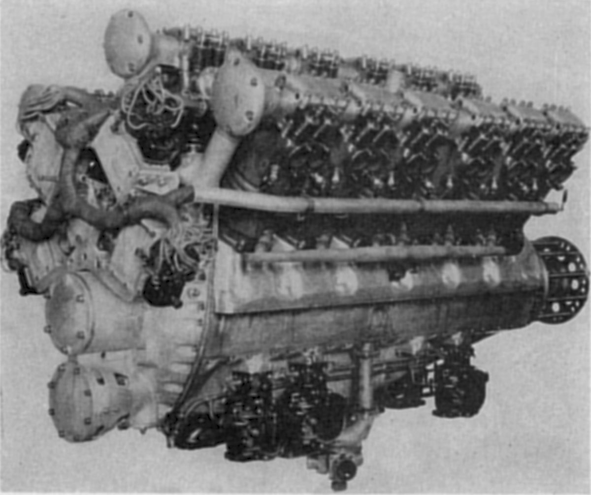
The Model W-1-A evolved from the W-1 after test completion. Six engines incorporating several minor design changes were built. Since no 18-cylinder magneto was available, three 6-cylinder magnetos were used for the first engine; later engines used four 18-cylinder Spitdorf magnetos. Eighteen-cylinder Delco replacement magnetos also were developed and tested.
Following a series of W-1-A endurance tests, a contract to build ten production engines and spares, known as the W-1-B, was awarded to the Packard Motor Car Company of Detroit, Michigan. Unfortunately, by this time attitudes toward government-funded engine development had soured and the W-1-B order was not completed. However, the experience gained proved extremely useful to the manufacturers developing larger-horsepower engines These W-series Engineering Division engines were the first successful eighteen-cylinder aircraft engines developed in the United States and also the first successful engines delivering over 800 hp.
 |
 |
 |
 |
 |
| Model | As Built | |||
 |
 |
 |
 |
 |
| Ends, Intermediate Main, Center Main, Longitudinal, Cam Drive |
 |
| E.N.V. (AEE) |
E.N.V.
The French and British-built E.N.V. (En Vee) engines were all water-cooled V-8s. The company was originally organized as the London and Parisian Motor Company, which was introduced in 1908. It had an 85 mm (3.347") bore, 90 mm (3.543") stroke, and 4.086 l (249.3 in³) displacement was rated 39 hp at 1,700 rpm and weighed 150 lb, or 3.8 lb/hp.
A larger model, also produced in 1909, with a 105 mm (4.134") bore, 110 mm (4.331") stroke, and 7.620 l (465.0 in³) displacement was rated 62 hp at 1,550 rpm and weighed 268 lb, or 4.6 lb/hp. A new company, the E.N.V. Motor Syndicate Ltd. of Willesden, England was organized to build these engines.
Another engine with a 100 mm (3.937") bore, 130 mm (5.118") stroke, and 8.168 l (498.4 in³) displacement was rated 55 hp at 1,000 rpm, 75 hp at 1,500 rpm and weighed 440 lb, or 7.3 lb/hp.
A later and more refined model, built in 1914, with a 95 mm (3.740") bore, 165 mm (6.496"), and 9.356 l (570.9 in³) displacement produced 100 hp at 1,620 rpm and weighed 450 lb, or 4.5 lb/hp. Fuel consumption was 0.51 lb/hp/hr. The valves were placed horizontally in the cylinder head.
References
Angle, Glenn D, ed. Aerosphere 1939 (New York, New York: Aircraft Publications, 1940).
Anble, Glenn D, ed. Airplane Engine Encyclopedia (Dayton, Ohio: Otterbein Press, 1921).
Image Sources: A39 = Aerosphere 1939; AEE = Airplane Engine Encyclopedia; Flt = Flight Magazine; NARA = U.S. National Archives and Records Administration; UKNA = United Kingdom National Archives.
Send mail to
![]() with questions or comments about this web site.
with questions or comments about this web site.
![]()