Selected Early Engines
A.B.C., Adams-Farwell, Aeromarine,
Ansaldo, Antoinette, Anzani, Argus
Compiled by Kimble D. McCutcheon
Published 15 Feb 2022; Revised 5 Mar 2022
A.B.C. Motors Ltd.
A. B. C. engines were built by the A. B. C. Motors Ltd., formerly the All British Engine Company Ltd. of London, England. Ronald Charteris organized A.B.C in 1912 to build automobile, aircraft and motorcycle engines along with automobiles, aircraft and motorcycles; Granville Bradshaw was chief engineer. An early four-cylinder vertical water-cooled aircraft engine was rated at 40 hp. This engine was used by Harry Hawker in a Sopwith biplane that won the Michelin Cup in 1912 by beating the British Duration Record.
A number of water-cooled Vee types having four, six, eight, twelve, and sixteen cylinders were designed based on a 3.75" bore, a 3.125" stroke, and 34.51 in³ cylinder displacement. The four-cylinder engine was rated 30 hp at 1,450 rpm. Its total displacement was 138.06 in³, and its bmep at rated output was 113.6 psi. Dry weight was 110 lb., or 3.167 lb/hp. The six-cylinder Vee type engine, displacing 207.06 in³, was rated 45 hp at 1,450 rpm and weighed 175 lb., or 3.9 lb/hp. The eight-cylinder engine displaced 276.12 in³, produced 6o hp at 1,450 rpm and weighed 175 lb, or 2.92 lb/hp.
Another A. B. C. water-cooled Vee-type engine series had a 5.0" bore, a 4.5" stroke, and displaced 88.36 in³ per cylinder. The six-cylinder Vee type, with a displacement of 499.8 in³ was produced 85 hp at 1,400 rpm. Its bmep was approximately 96 psi and its dry weight was 220 lb., or 2.59 lb/hp. The eight-cylinder 90-degree Vee type displaced 706.88 in³ and produced 100 hp at 1,300 rpm with an 86 psi bmep. The valves were located in the cylinder head and mechanically operated. The dry weight was said to be 375 lb., or 3.75 lb/hp. The twelve-cylinder Vee type produced 170 hp at 1,400 rpm from a 1,000 in³ displacement and a 390 lb dry weight, or 2.3 lb/hp. A sixteen-cylinder Vee type was designed but never built. This engine would have displaced 1,332.8 in³, and was rated 225 hp at 1,400 rpm from a 490 lb dry weight, or 2.18 lb/hp. Apparently, few of these Vee-type engines were produced.
|
| Gnat (AEE) |
During 1913, A.B.C. began to develop air-cooled engines. The smaller of these, known as the Gnat, was a two-cylinder horizontally-opposed type, while the others were radials. The Gnat, introduced in 1916, had a 110 mm (4.33") bore, a 120 mm. (4.72") stroke, a 139 in displacement, and produced 45 hp at 1,800 rpm. Dry weight was said to be 115 lb, or 2.56 lb/hp.
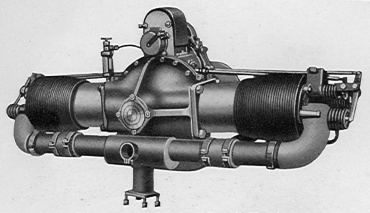
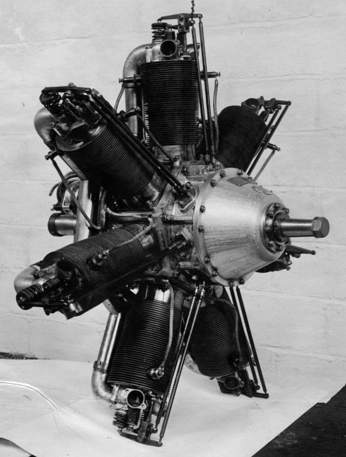
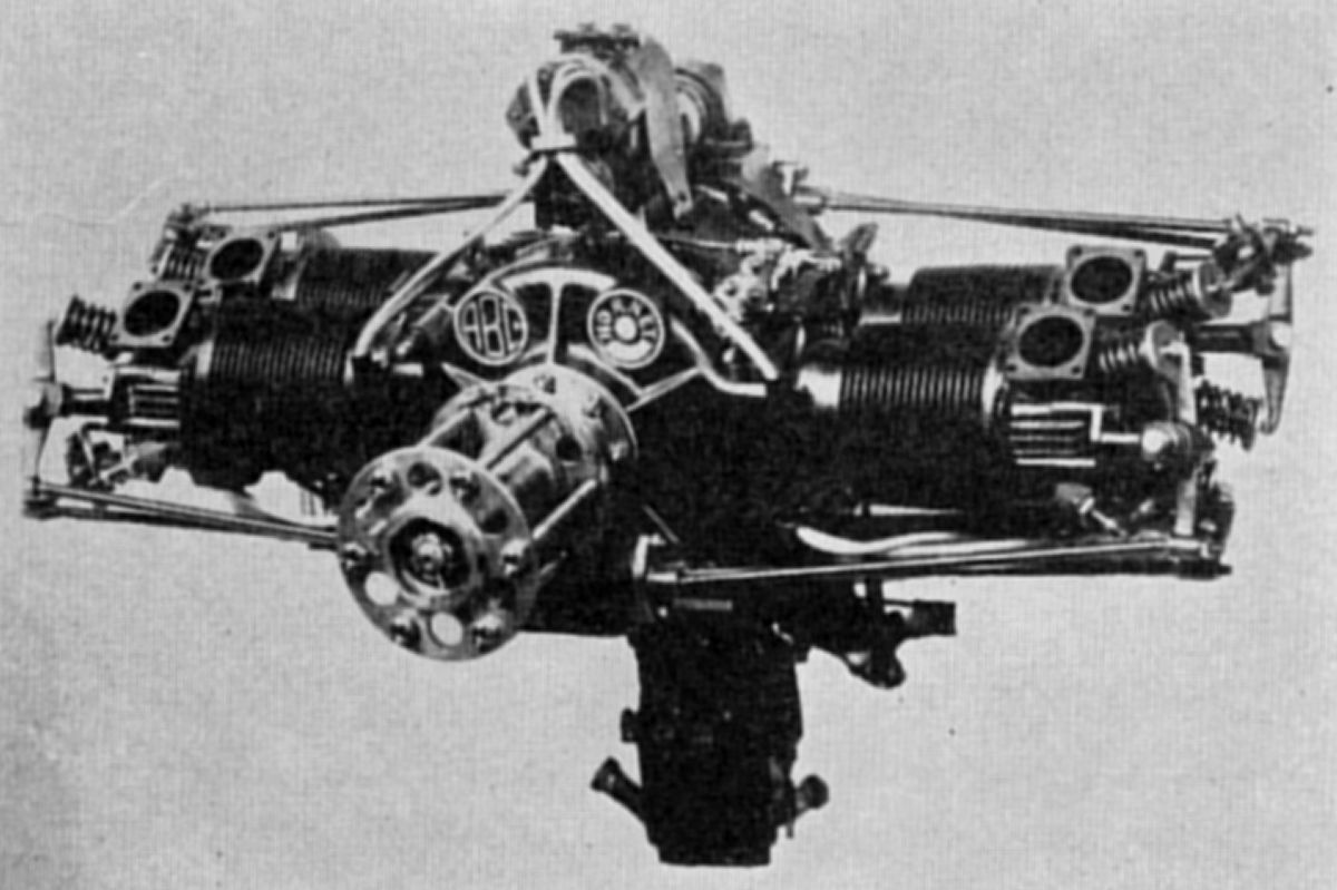
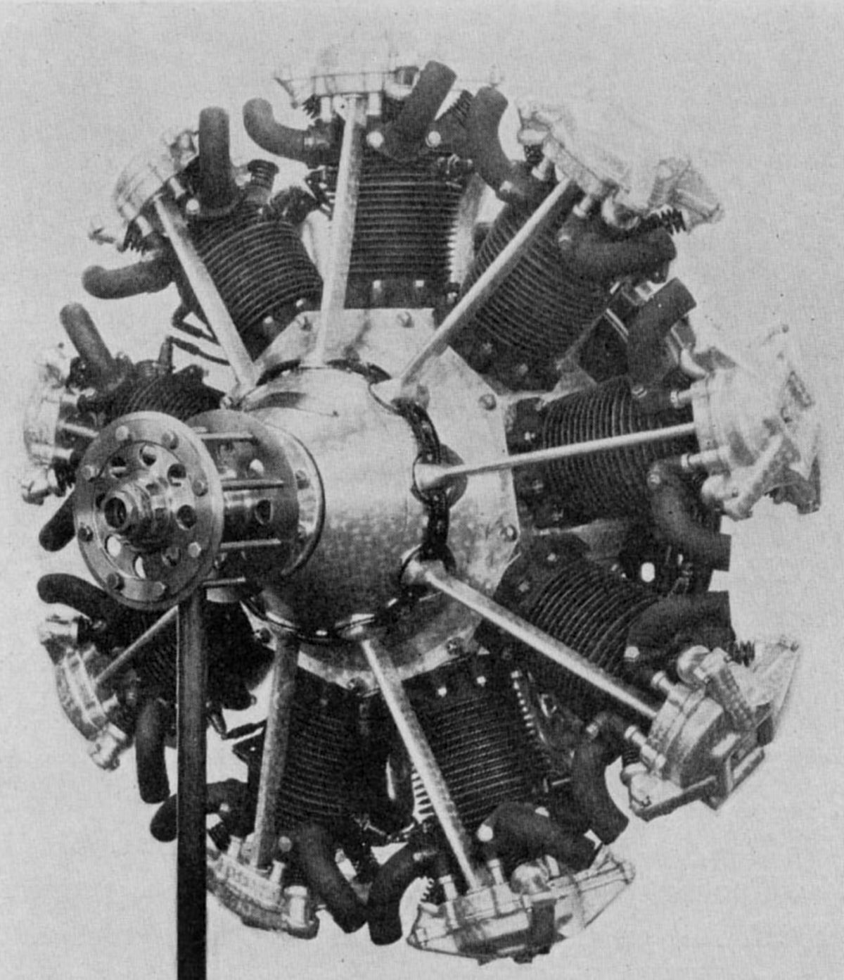
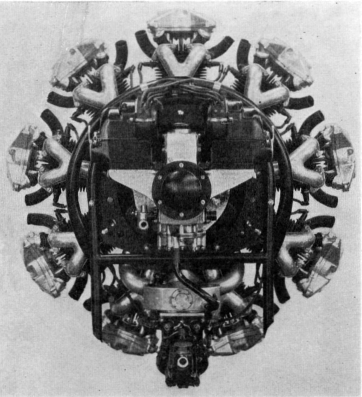
Around October 1917, A.B.C. submitted to the government an experimental 7-cylinder radial of 657 in³ that produced 170 hp and weighed 290 hp. Bradshaw immediately submitted a larger, 9-cylinder 1,689.3 in³ design that he claimed would produce 340 hp and weigh about 600 lb. With a 5.5" bore, a 6.5" stroke and a 4.42:1 compression ratio the Dragonfly was designed for easy production and was supposed to produce 320 hp at 1,650 rpm and 340 hp at 1,750 rpm. Copper plated cooling fins were supposed to keep the cylinders cool, but this scheme flew in the face of ground-breaking air-cooled cylinder research being done by A.H. Gibson and S.D. Heron at the Royal Aircraft Establishment. The British WWI aircraft production effort was in dire need of engines, and both the government and aircraft manufacturers thought the Dragonfly was the most promising engine available. Thousands were ordered and contracts for most other engines were cancelled. When the Dragonfly was actually tested in 1918, it weighed 656 lb, produced only 315 hp and overheated badly; at 1,650 rpm it produced less than 295 hp. The actual bmep at normal speed was approximately 103 psi, the fuel consumption was supposed to have been 0.56 lb/hp/hr, but under test the value was as high as 0.80 lb/hp/hr. Oil consumption was stated to he .039 lb/hp/hr. Worst of all, Bradshaw's design featured a crankshaft whose primary torsional vibration mode was dead in the middle of the engine's operating rpm range. The Dragonfly contract was cancelled, but not before 1,147 were built by A.B.C and numerous other companies.
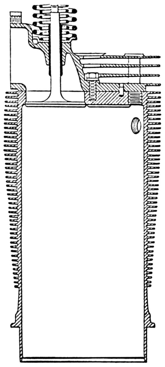
The Dragonfly used two Claudel-Hobson H-C-S carburetors that were mounted at the anti-propeller end and fed at four points into a baffled ring manifold from which pipes were connected to each cylinder. Cylinders were machined from steel forgings with head and cooling fins integral. The cooling fins were plated with copper for the combined purpose of distributing the heat and to assist in dissipating it to the cooling air. The exhaust and inlet valve ports were bolted to the cylinder head. There were three valves per cylinder, one 2.66" inlet with a 0.654" lift, and two 1.7" exhaust valves with a 0.413" lift located forward. The inlet valve opened at top center and closed 52° late, and the exhaust valve opened 64° early and closed 10° late. The single-throw crankshaft was built up in two sections with counterbalances integrally attached to each. Articulated connecting rods were attached to a master rod with a solid-ring big end mounted upon roller bearings. The pistons were made of aluminum alloy and had three rings located above the piston-pin. Dual ignition was provided by two nine-cylinder magnetos. The Dragonfly was 47.52" high, 48.5" wide, and 42.12" long.
 |
 |
 |
 |
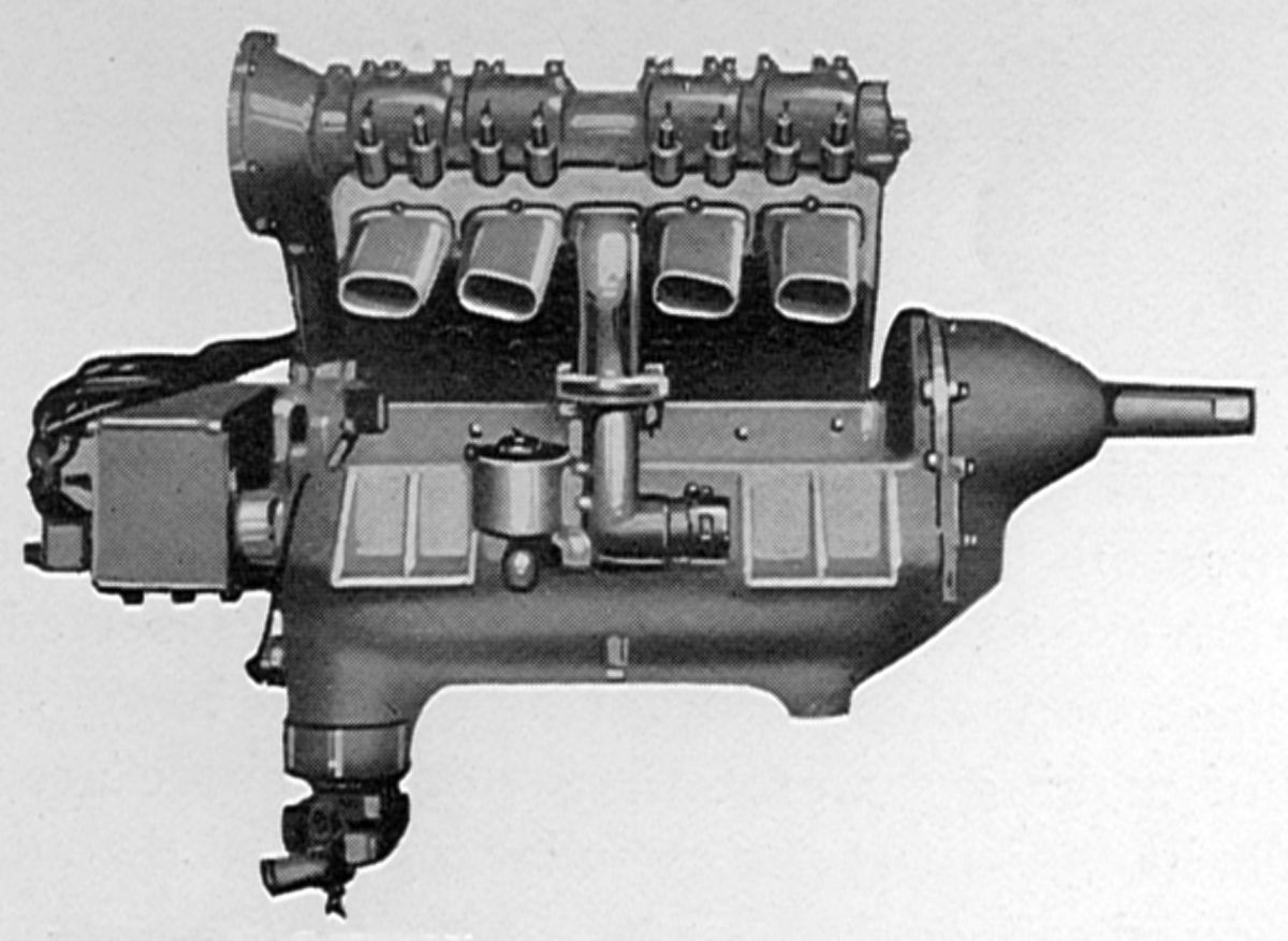
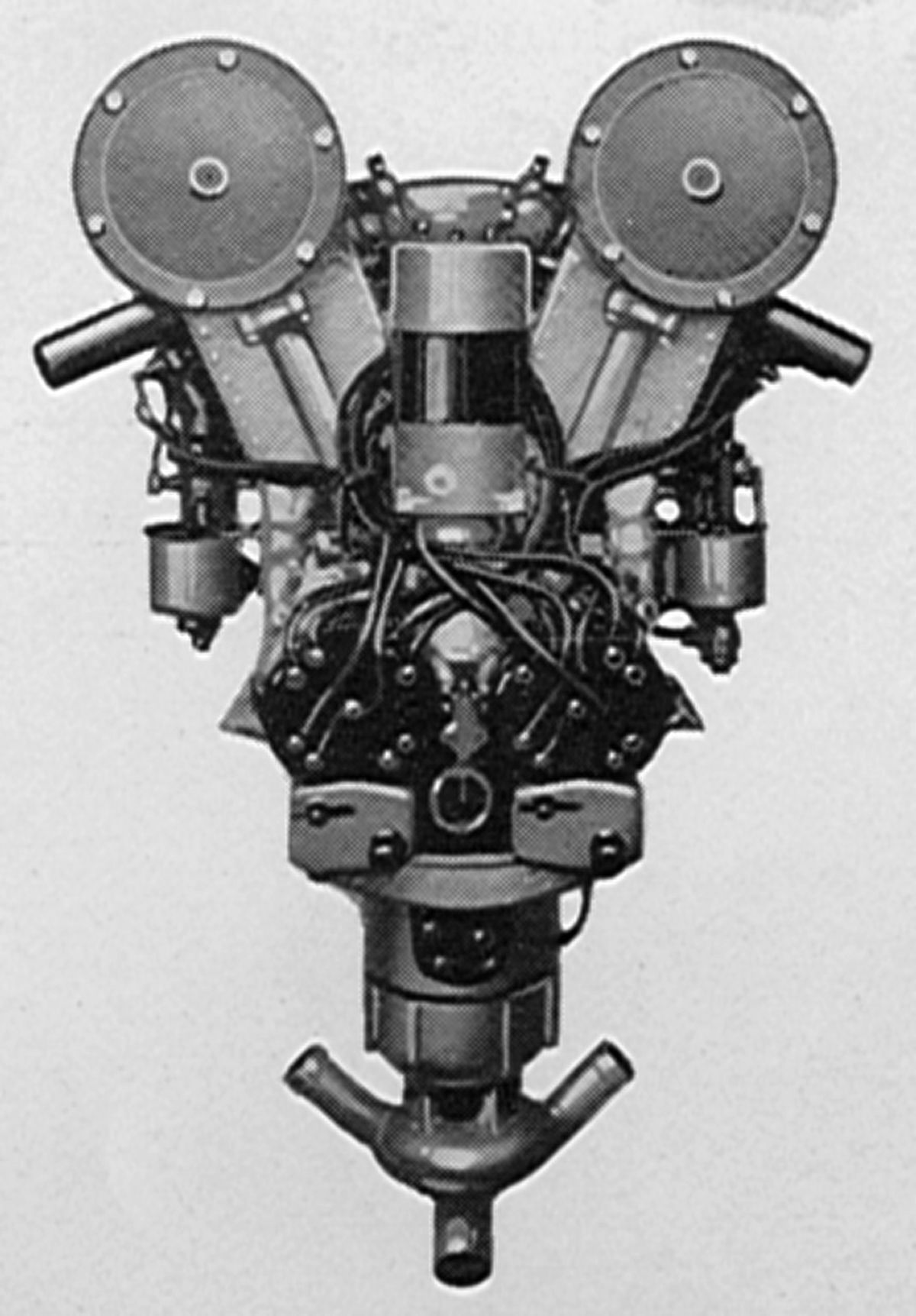
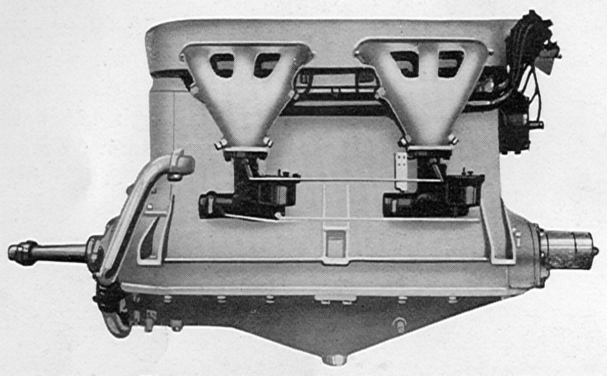
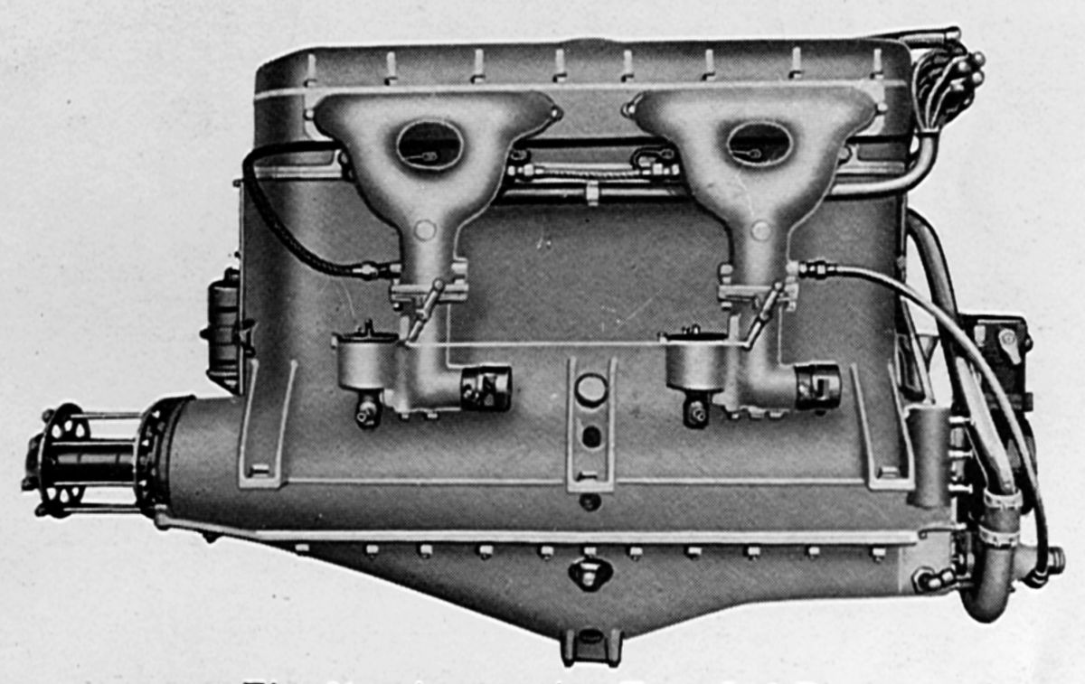
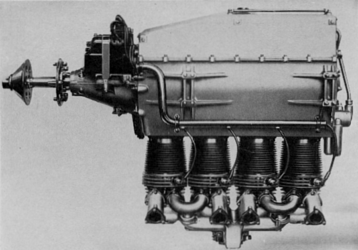
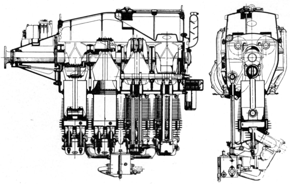
| Fore (NARA) | Right (NARA) | Aft (NARA) | Cylinder Section (NARA) |
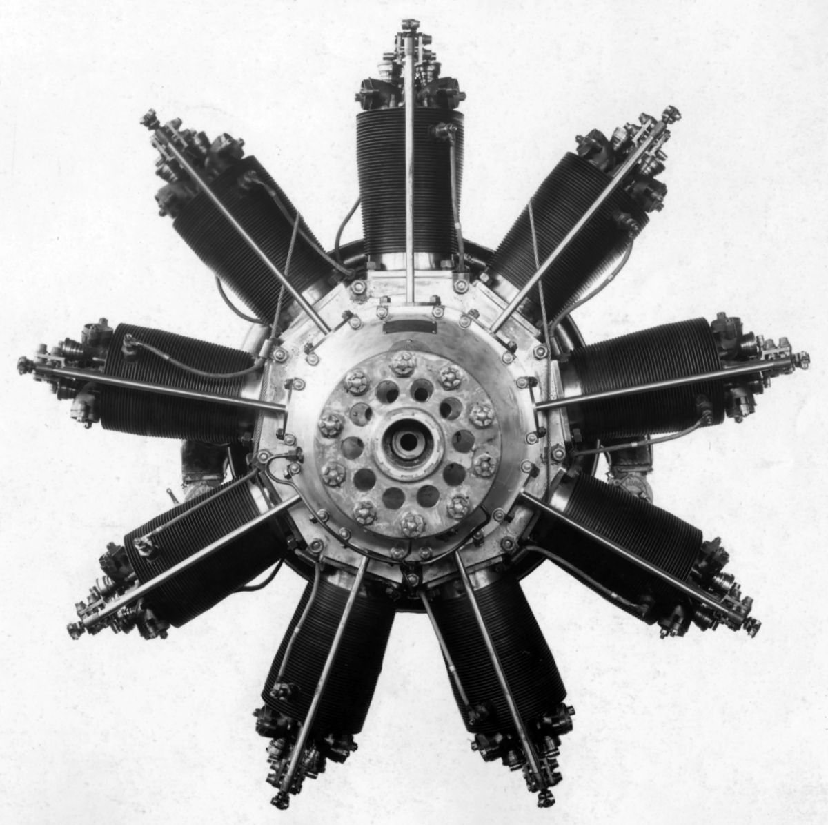
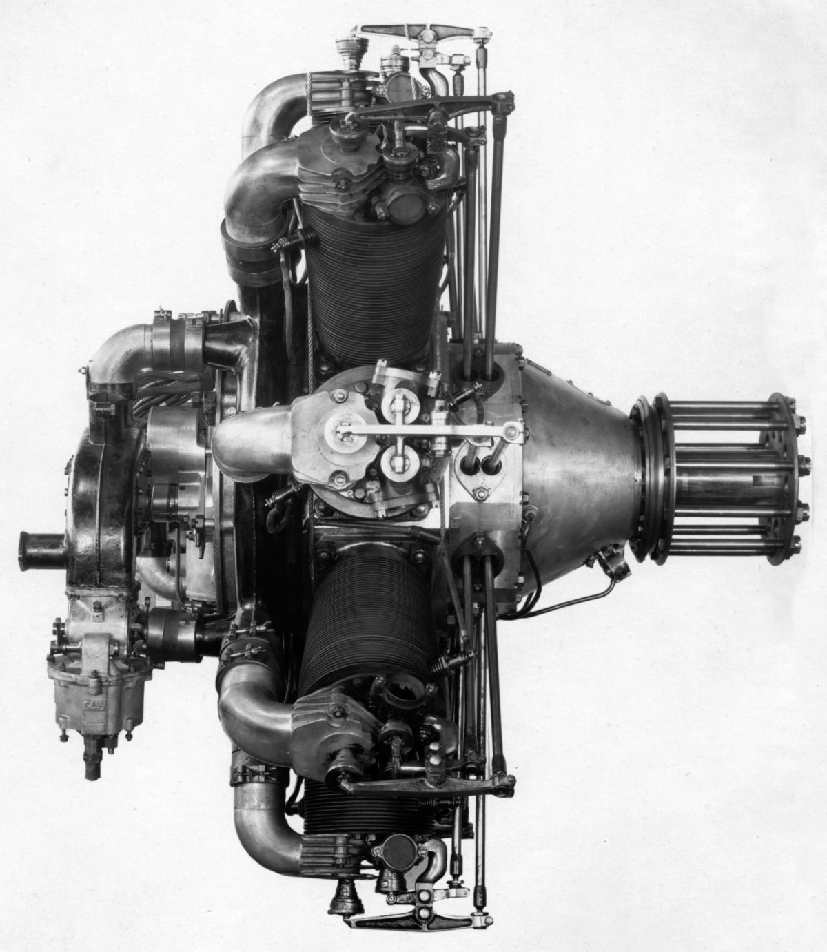
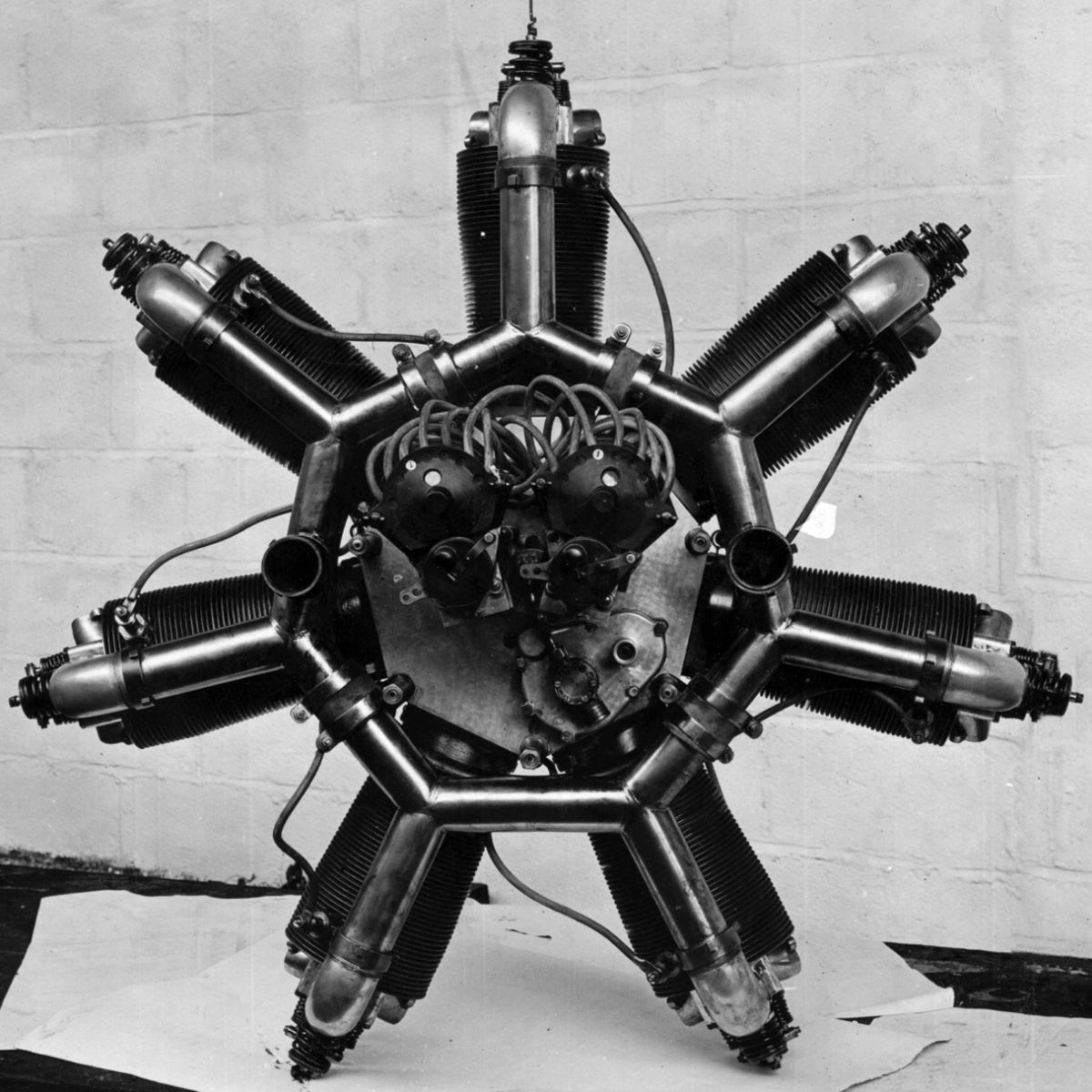
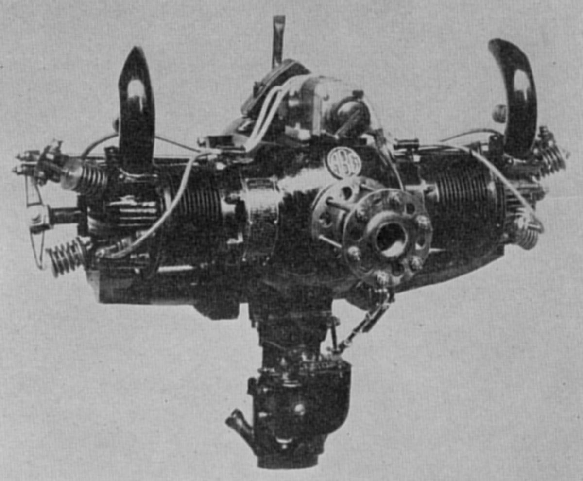
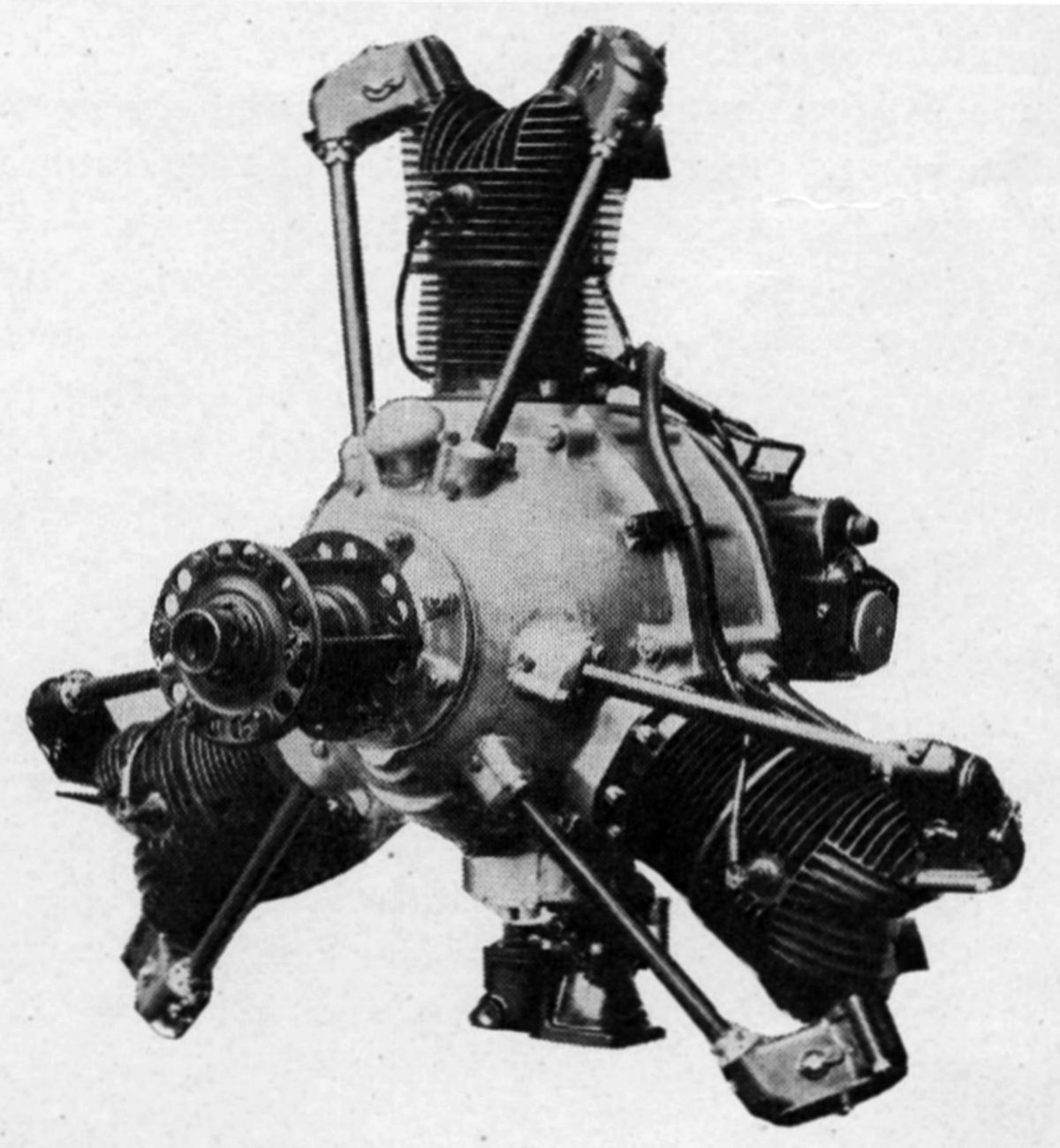
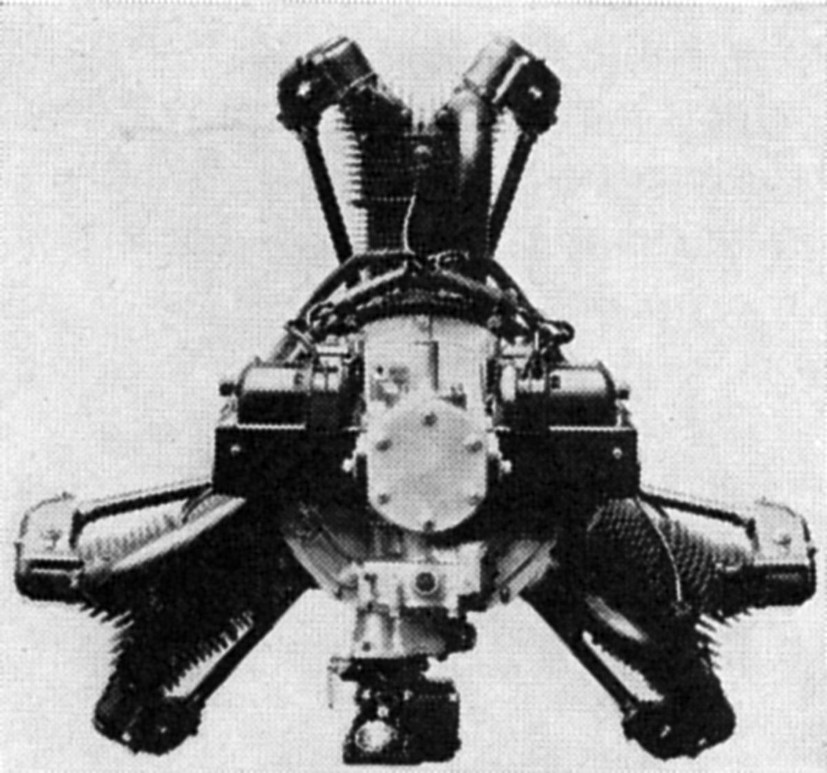
The A.B.C. Wasp Mark I, a Dragonfly contemporary released in 1918, was a production version of the earlier experimental seven-cylinder air-cooled radial with a 114.3 mm (4.5") bore, 150 mm (5.9") stroke and 667 in³ displacement. Weighing about 290 lb, it produced 170 hp at 1,800 rpm, for a 111 psi bmep. Specific fuel consumption was 0.592 lb/hp/hr and oil consumption was 3.42 1b/hr.
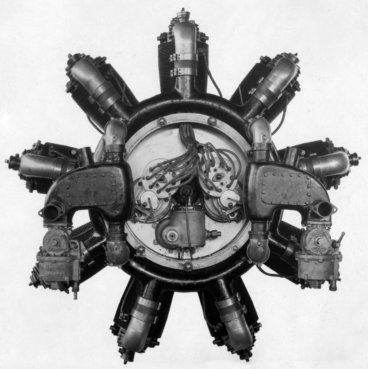
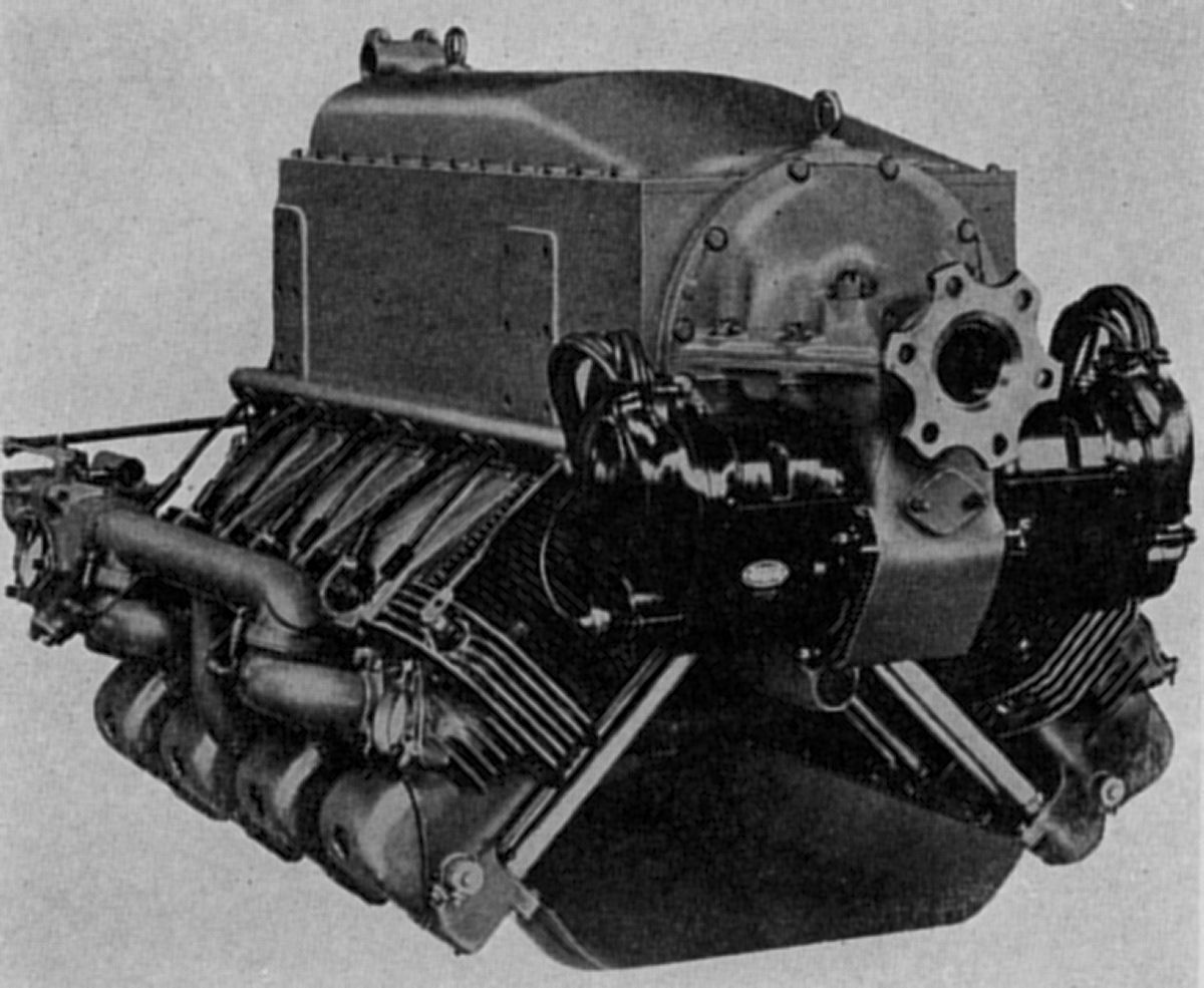
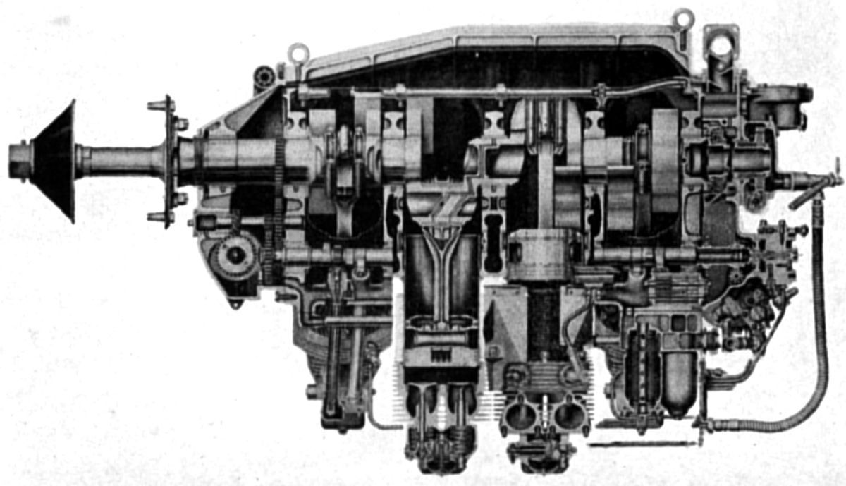
The Wasp Mark II was a slightly later (still 1918), improved design with a larger 4.75" bore, 6.25" stroke and 775 in³ displacement. The compression ratio was 4.57:1. Its normal rating was 160 hp and its maximum output was 176 hp at 1,650 rpm. Specific fuel consumption was 0.70 1b/hp/hrhr and the specific oil consumption 0.03 lb/hp/hr. Dry weight was 350 lb for an engine that was 45" long with a 42.7" diameter.
 |
 |
| Right Fore (NARA) | Aft (NARA) |
A. B. C. Motors, Ltd. did very little with aircraft engines from 1919 until 1923, at which time air-cooled engine development for light aircraft commenced. Converted A.B.C. motorcycle engines were used in light planes beginning around 1921. Among these were air-cooled two-cylinder opposed engines with a 69 mm (2.72") bore, 54 mm (2.13") stroke, and 24.75 in³ displacement. It produced 7 hp at 4,000 rpm, 8 hp. at 4,500 rpm, and weighing 40 lb for a 5.72 lb/hp specific weight. A. B. C. built 10 and 20 hp engines that were used to power aircraft.
 |
| Scorpion Mark II (A39) |
The Scorpion Mark I was the first of this type. It was a horizontally-opposed two-cylinder air-cooled engine having a bore and stroke of 3.6" and a displacement of 73.25 in³. With a compression ratio of 4:1 it developed 24 hp at 2,500 rpm from a 90 lb dry weight.
The slightly larger Scorpion Mark II had a 4.015" bore, 3.6" stroke, and a 90 in³ displacement. It produced 34 hp at 2,300 rpm and 40 hp at 2,750 rpm and a 6:1 compression ratio. It was 32" wide, 15.5" long, 26" high and weighed 109 lb.
Scorpion cylinder barrels with integral cooling fins were machined from solid steel bars. Detachable heads were liberally finned iron castings with hemispherical combustion space accommodating two interchangeable valves and two spark plugs. Eight studs held the cylinder head to the barrel, and the whole assembly was attached to the crankcase by four studs. The valves were operated via tubular push rods and rocker arms on hollow pins with an oil reservoir. The short, rigid, two-throw crankshaft was machined from a one-piece alloy-steel forging. Connecting rods were forged from the alloy steel The aluminum alloy pistons were featured two compression rings above the wrist pin, and an oil scraper below. Early wrist pins were fixed in the connecting rod small end and were full-floating in the later models. The connecting rod big end used a plain floating bronze bushings that were split longitudinally, being inserted and joined by screws after the rod was threaded in position over the crank-pin. Propeller thrust was carried on a ball bearing, and all other bearings were either ball or roller. One inlet and one exhaust cam were formed integrally with the short camshaft, with each cam serving both cylinders. Roller type tappets slid in duplex plain bearings. The dry-sump lubrication system used rotary pumps for pressure and scavenging. A. B. T. H. magneto of special design provided ignition, giving two sparks to each cylinder. This unit was fitted with an impulse starter. It was also interconnected with the throttle so that timing was fully advanced at throttle positions above one quarter. Early engines used special double-choke triple-diffuser Zenith carburetors bolted directly to the crankcase, and an exhaust heater for the inlet air. Later engines were fitted with improved Claudel carburetors.
 |
| Hornet (A39) |
The A.B.C. Hornet of 1929 doubled the Scorpion concept with two horizontally opposed air-cooled cylinder pairs. The engine's rated output was 75 hp at 1,875 rpm, and its maximum output was 82 hp at 2,175 rpm from a 4.015" bore, 4.8" the stroke, 243 in³ displacement and 5.6:1 compression ratio. Early engines weighed 225 lb, but improvements increased this to 245 lb. The latest bare dry weight was reported to be 219 1b. It was 25.5" long, 39" wide and 28" high.
All Hornet cylinder head parts were interchangeable with the Scorpion. The two-throw crankshaft was supported on two roller bearings in front, one plain bronze bearing between the throws, and one roller bearing at the rear. The connecting rods were the same as used in the Scorpion. Four long bolts held the three crankcase sections together and were also used for mounting. A camshaft in the top rear crankcase section operated rear-cylinder valves; another in the crankcase bottom front section served the two front cylinders. Early Hornets used a single Watford double-spark magneto and a duplex Zenith carburetor. Later engines used two B. T. H. magnetos and a Claudel carburetor.
Apparently these later A.B.C engines did not sell, plus there was the matter of the Great Depression. A.B.C suspended Scorpion and Hornet manufacturing indefinitely to concentrate on auxiliary power units. A.B.C was absorbed by Vickers in 1951 and had ceased activity entirely by 1970.
 |
 |
| A.B.C. Midge (Fey) | A.B.C. Midge Dataplate (Fey) |
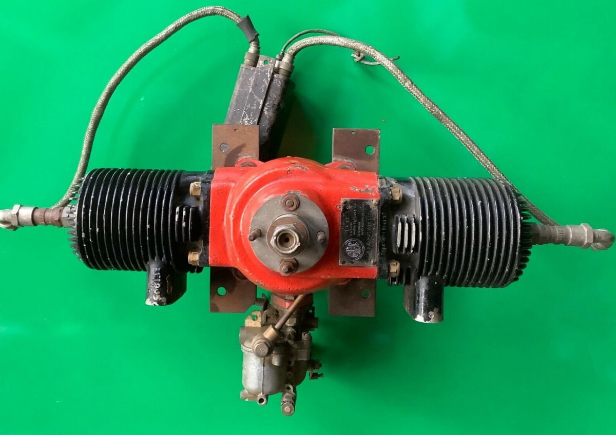
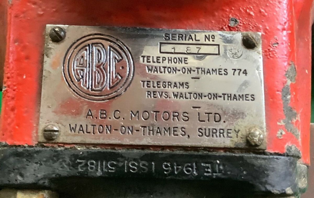
According to WWII drone expert Tom Fey, “In the early 1950s A.B.C. was contracted to build the ‘Midge’, which was essentially the Righter 0-15-3 engine, to support their home-island built Auster No.2 Mk 1 aerial gunnery target drones. I wrote up the info below accompanied by 14 photographs for the WWII Dronehead Facebook collection (22 Nov 2021).” “Although not a true WWII target drone, the 1950s Auster B3 / Pilotless Target Aircraft No.2 Mk. 1 has its origins in the Radioplane OQ-3 / TDD-2 aerial gunnery target. The British training services desired their own subscale gunnery target, but post-war monetary policy prevented their purchase of the American Radioplane aircraft. After much delay, the Auster Company produced 150 No.2 Mk. 1 targets between April 1951 and January 1953. The drone was powered by a slightly modified version of the Righter 0-15-3 engine named the ‘Midge’, which was manufactured in Britain by A.B.C. Motors Ltd. Although no Mk. 2 No.1 Pilotless Target Aircraft are known to exist, at least three A.B.C. Midge engines are extant, two of which are complete in their original shipping crate with ancillary components. The A.B.C. Midge drone engine was a copy of the Righter 0-15-3 design but was run much more conservatively (6 hp @ 3,200 rpm) than the Righter 0-15-3 (8 hp @ 3,800 rpm). The Midge used British aircraft-style spark plugs and wiring, a British dual coil, and a Zenith Type 24T carburetor in place of the American Tillotson YC3A.”
Adams-Farwell
 |
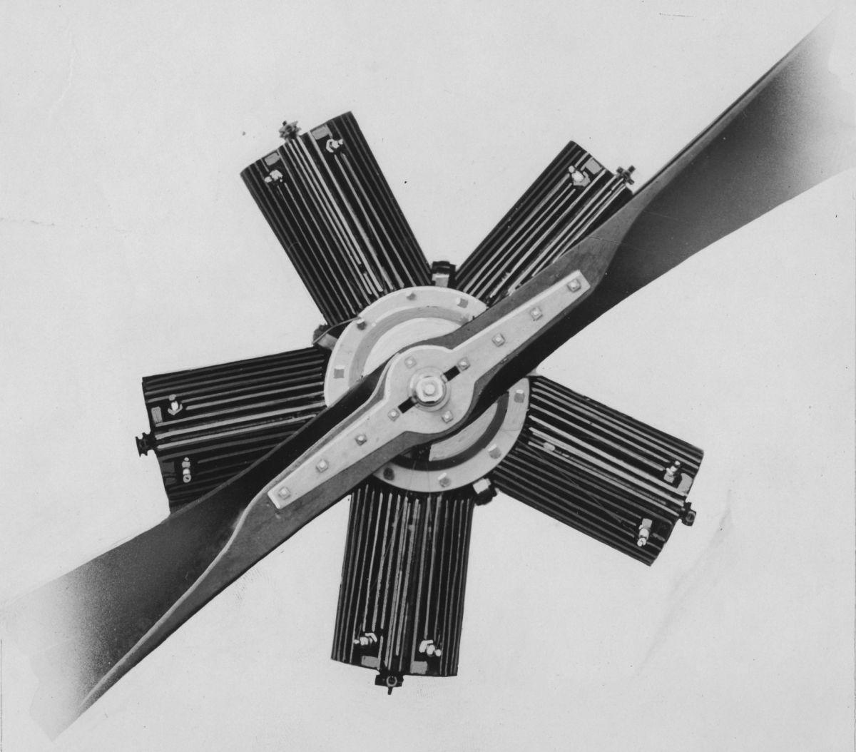
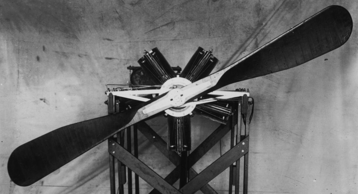
| Adams-Farwell Rotary of the Type Used by Berliner and Williams (NASM) |
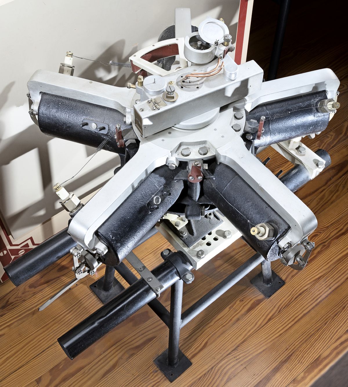
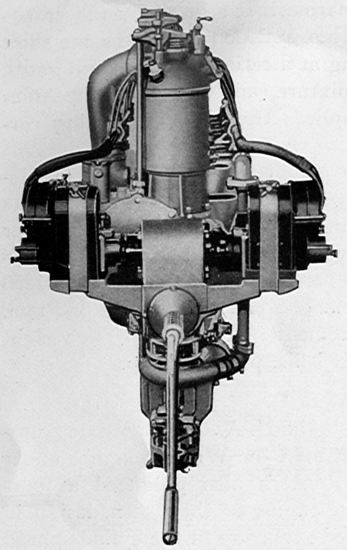
Between 1883 and 1892, Eugene and Herbert Adams acquired the Roberts & Langworthy Iron Works of Dubuque Iowa, which ultimately became the Adams Company, a foundry and machine shop. In 1895, Fay Oliver Farwell became the Adams Company manager. At the same time, Farwell began work on an automobile driven by a 3-cylinder rotary engine whose rotation axis was vertical. A 5-cylinder engine was designed and the 5th such car was exhibited at the Chicago Auto Show in February 1905, at which time the Adams Company began taking orders for its Model 6, one of which is still operational (video).
A modified 1907 Adams-Farwell engine became the first rotary engine to fly, driving a vertical shaft that powered experimental helicopters designed by Emile Berliner. Other Adams Company light gyrocopter engines powered more Berliner experimental flying machines in 1909-1910, as well as one by J. Newton Williams in 1909. Engine production continued beyond automobile manufacture.
Later, the same engine design was fitted with a bevel gear drive for a horizontal propeller shaft. The first airplane flight ever made with a rotary engine was by Charles K. Hamilton at Seattle, Washington on 11 Mar 1909. These first Adams-Farwell air-cooled rotary airplane engined had five cylinders and produced 36 hp at 1,000 rpm, with a 1,500 rpm maximum speed. The bore was 4.25", the stroke 3.25", and the displacement 248.25 in³. The engine had no cooling provisions of any sort. The steel cylinders had no external cooling ribs, but nevertheless cooled quite evenly, due to the rapid air circulation on their outer surfaces when in motion. No springs were used on either intake or exhaust valves, as they were held to their seats while running by centrifugal force. All valves were operated by one cam, and a single push/pull rod and rocker arm served both valves of one cylinder. The inlet valve was opened by the centrifugal force of the rod while the rocker acted upon the exhaust valve stem as its fulcrum, thereby insuring gas tightness for the closed valve.
An inlet pipe located directly behind each cylinder conducted the fuel/air mixture from the mixing chamber. Due to centrifugal action, the mixture was forced into the cylinders under pressure. The speed of the engine was controlled by a variable cam that regulated the closing of the inlet valve so as to retain only the required charge in the cylinder. The ignition consisted of a single-pole timer, a three-pole coil with a single vibrator, and a storage battery. The engine's dry weight was 97.25 lb, or 2.7 lb/hp. Overall diameter was 27", and the height was 16".
It was not long before the Gnome engine appeared in France and soon became widely known as a result of the many records it established. The Gnome engines, which embodied most of the principal features brought out in the Adams-Farwell designs, were copied by several other firms.
 |
 |
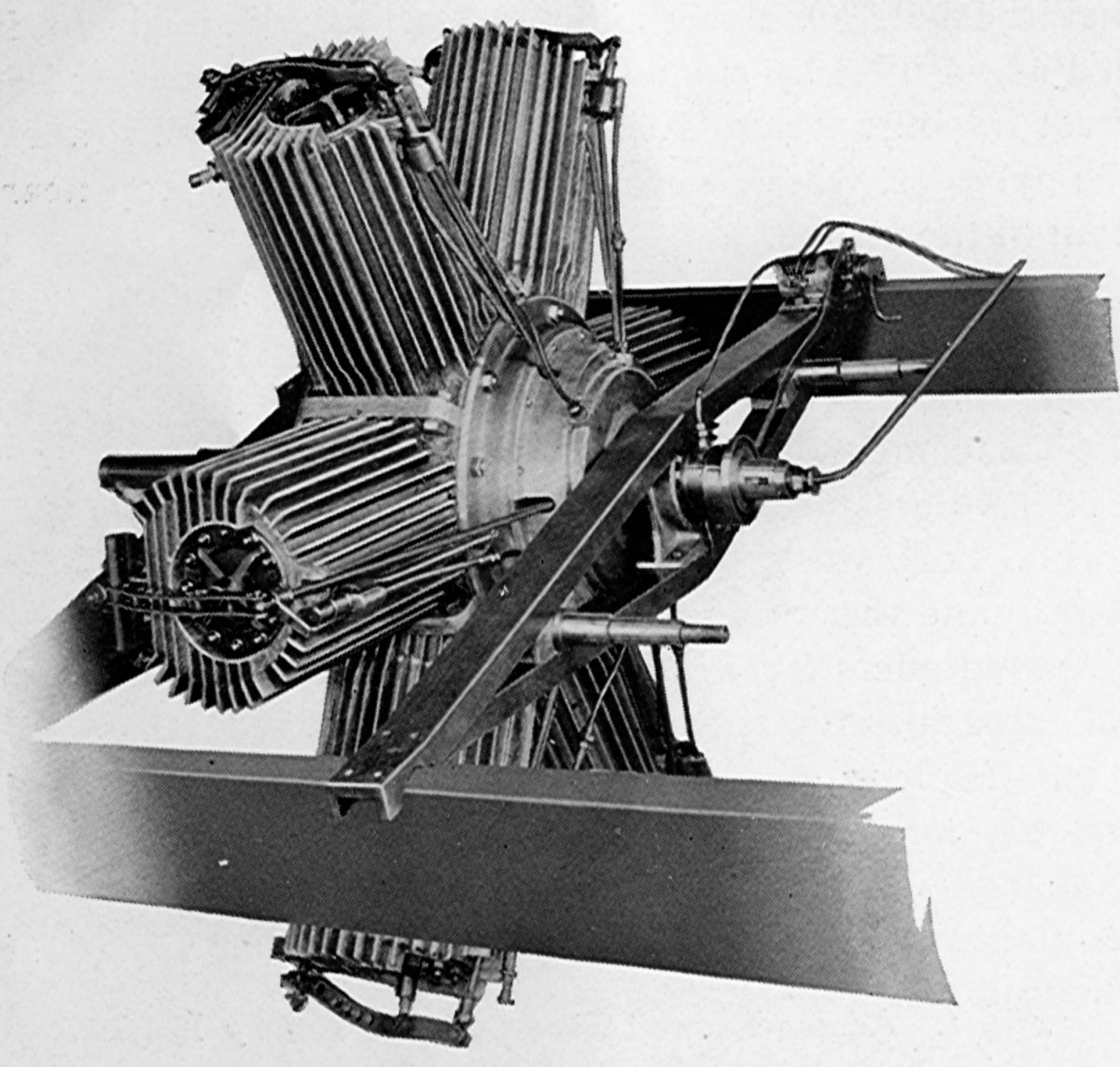
| Adams-Farwell 36 hp Rotary (NARA) | Variable Compression Adams-Farwell Engine (NARA) |
Another Adams-Farwell engine also had five rotating cylinders, produced 63 hp at 800 rpm and was capable of running up to a maximum speed of 1,200 rpm. Its bore was 5.625", stroke was 5.000", and displacement was 621.25in³. The cylinders were made from cast iron with integral longitudinal cooling fins, but in all other respects the design was quite similar to the 36 hp engine. The second rotary engine's
dry weight was 250 lb, or 3.96 lb/hp. Its diameter was 34"., and it was 20" high.
A third enlarged Adams-Farwell engine design had a 5.25" bore, a 5.000" stroke, and a 541.2 5in³ displacement. Rated at 55hp, it weighed 165 lb, or 3.0 lb/hp. Its overall diameter was 34" and its height 20".
In 1910 the Adams Company brought out a still larger and more powerful engine design with its cylinders in the vertical plane and employing a new induction system. It had a 6.000" bore and stroke, and displaced 833.23 in³. Originally rated 72 hp, the engine normally ran at speeds from 950 to l,000 rpm. With further development, the output increased to 135 hp. The induction system used no carburetors; instead fuel was injected into each cylinder with power control by governing the fuel quantity injected. One valve, located in the cylinder head, functioned as an air inlet and operated as an exhaust in conjunction with auxiliary ports in the lower cylinder, which were uncovered by the piston near its stroke bottom. Pressure lubrication was furnished by a pump consisting of a rotary member with plungers in longitudinal chambers that were operated from end to end by stationary cams. The cylinders were made from iron with integrally cast longitudinal cooling fins. The pistons were made from cast iron and fitted with four rings. Dual ignition was employed. The dry weight was 285 lb, or 3.96 lb/hp at the original rated output and 2.1 lb/hp. for the fully developed engine.
 |
| Adams-Farwell Double Rotary (AEE) |
Realizing that increasingly higher power would lead to rotary engines whose gyroscopic action would impact aircraft control, the Adams company began experimenting with fixed radials employing counterweighted crankshafts. Such engines exhibited excessive vibration
A double-rotary engine fitted with two propellers turning in opposite directions was the last Adams-Farwell development. It had six cylinders with 6.000" bores and strokes, and displaced 1,017.9 in³. The output was estimated to be 280 hp and the weight 279 lb, which would have represented an engine weighing less than 1 lb/hp, a noteworthy engineering accomplishment if practicable. The novel feature was the piston and cylinder materials. The piston was of cast steel, while the cylinder, with its longitudinal cooling fins, was cast from aluminum alloy and not fitted with a liner. Although the reverse of ordinary practice, it was said that the cold clearance between the piston and cylinder remained practically constant during running since the different coefficients of expansions compensated for their working temperature differences. As with some of the earlier models, there was one valve in the head and auxiliary exhaust ports near cylinder base. The fuel was injected and one cam controlled the valves in all cylinders. The crankshaft revolved counterclockwise at 1,200 to 1,500 rpm, driving a lower pitch propeller, while the cylinders revolved in a clockwise direction at 1,000 to 1,200 rpm, driving a higher pitch propeller.
A series of 5.000" bore and stroke double-rotary engines having cast aluminum-alloy cylinders and cast or forged steel pistons was proposed by Farwell. These were to have 6, 10, 14 and 18 cylinders, with the 10, 14 and 18-cylinder versions using cylinders screwed and clamped in the crankcase.
The Adams Company is still in business, producing custom gears, shafts and power transmission parts for agricultural and construction machinery, oil recovery equipment, winches, industrial pumps and parts for other such industries.
Aeromarine
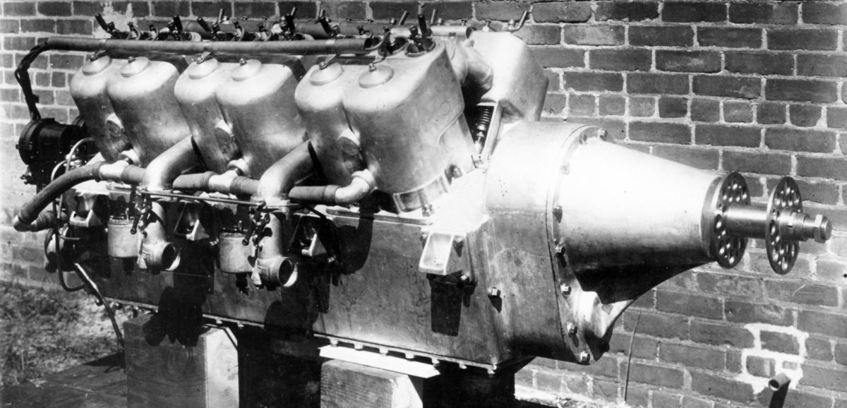
Frank Edward Boland (31 Jul 1873 – 3 Jan 1913), James Paul Boland (20 Aug 1882 – 19 Dec 1967) and Joseph John Boland (27 May 1879 – 12 Sep1964) were bicycle racers, aircraft designers, and bicycle, motorcycle and automobile mechanics who formed the Boland Airplane and Motor Company around 1908 in Rahway, New Jersey. Boland introduced a series of water-cooled V-8 aircraft engine from 1908 until 1914.
Inglis M. Uppercu (17 Sep 1877 - 7 Apr 1944) was a successful automobile dealer in New York and New Jersey who helped fund the Boland brothers' aeronautical experiments. In 1914, Uppercu founded the Aeromarine Plane and Motor Company of Keyport, New Jersey with Uppercu as president. Aeromarine acquired the Boland assets, began making Boland aircraft and engines, and started producing aircraft and engines of its own design. The firm became the Aeromarine-Klemm Corporation in 1928 and began producing mostly designs of Dr. Hanns Klemm of the German Klemm Leichtflugzeugbau GmbH, under license. Aeromarine-Klemm ceased operation in 1930, a victim of the Great Depression, but a few Aeromarine engine designs continued to be built and sold by the Uppercu-Burnelli Corporation.
 |
 |
 |
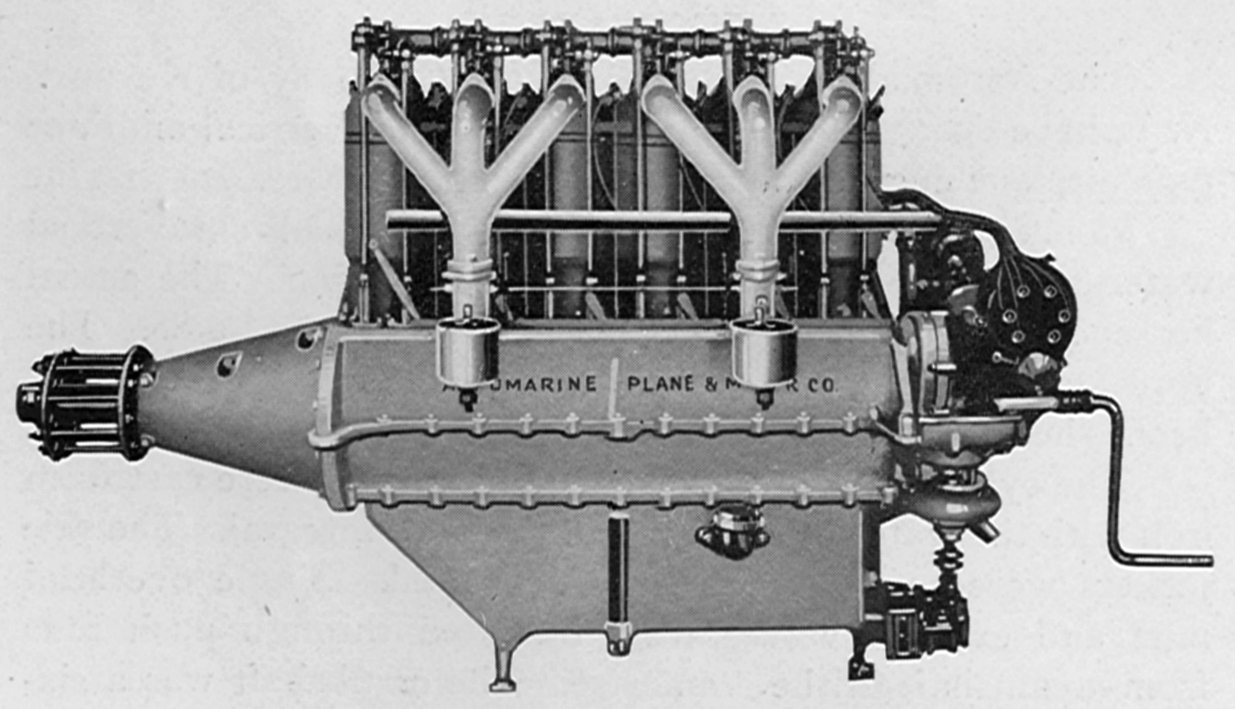
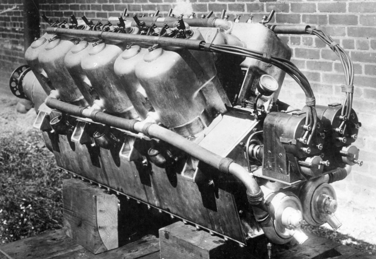
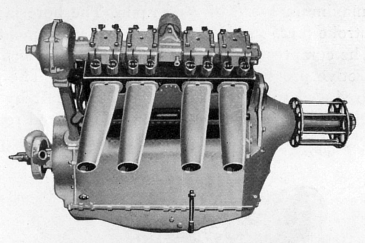
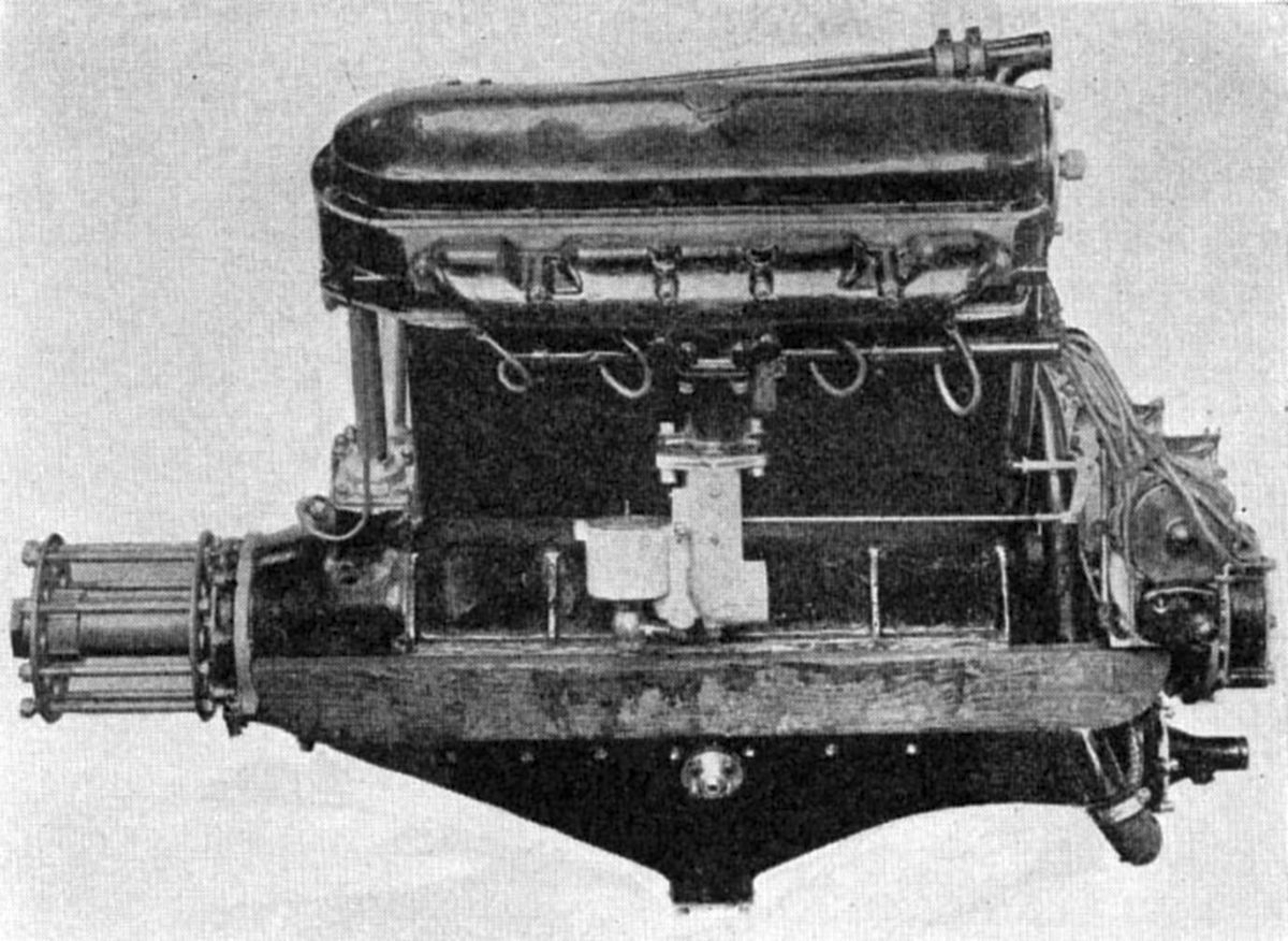
| Aeromarine 90hp (AEE) | Aeromarine K-6 (AEE) | |
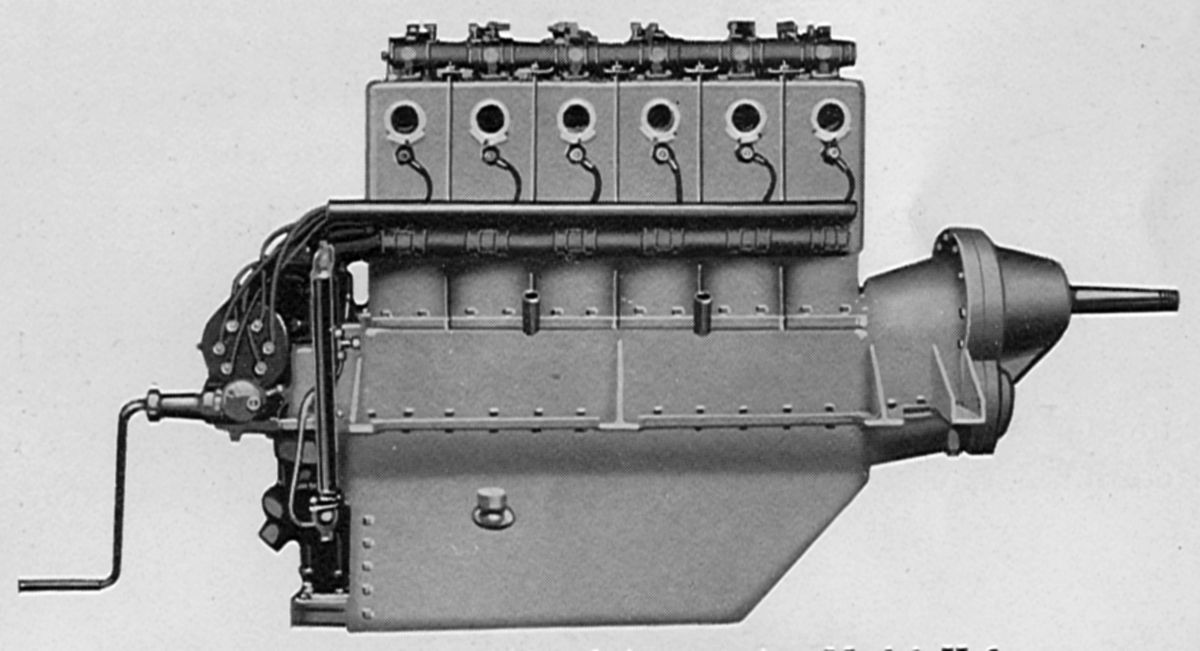
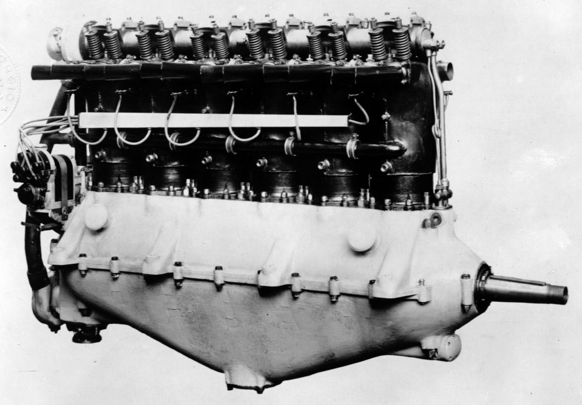
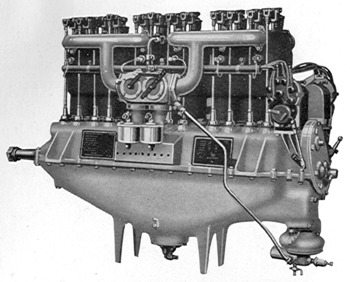
The Aeromarine 90 hp, the first Aeromarine engine, had six vertical water-cooled cylinders and developed its rated power at 1,400 rpm. With a 4.313" bore and 5.125" stroke, the engine displaced 449.16 in³. The cast-iron cylinders had donut-shaped heads and integral water jackets. The side jackets were electrolytically-deposited copper. Single overhead inlet and exhaust valves were operated through push rods from a camshaft in the crankcase. The crankshaft was a six-throw seven-main-bearing type with H-section connecting rods. The pistons were cast iron. Mixture was supplied by two Zenith carburetors, each feeding three cylinders. Oil pressure from 12 to 15 psi was maintained by a gear pump, and two Bosch D-U-6 magnetos provided ignition. Dry weight was approximately 430 lb.
 |
 |
| Aeromarine 100hp (AEE) | |
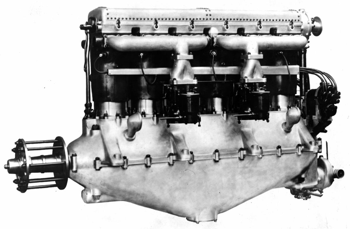
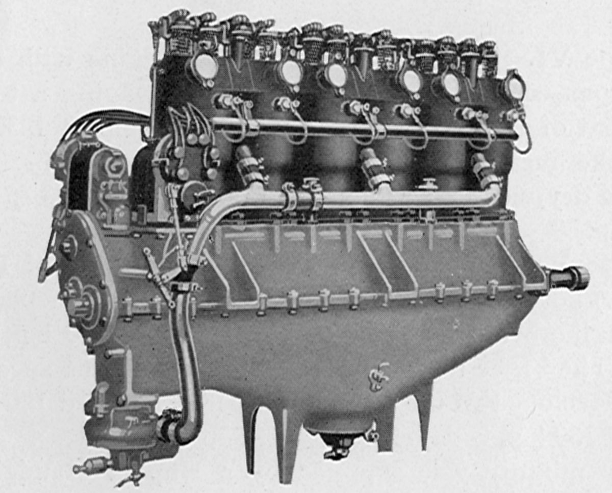
The geared Aeromarine K-6 produced 100 hp. at 2,000 rpm The propeller reduction ratio was 1.7513:1. Two Zenith carburetors furnished the mixture, and pressure lubrication was maintained by a gear pump. The fuel consumption was 0.63 lb/hp/hr and oil consumption 0.063 lb/hp/hr. The six-throw crankshaft had seven plain main bearings with individual caps, and ball bearings mounted on each side of the driving gear. H-section connecting rod shanks were used, and dual ignition was supplied by magnetos. The engine weighed 435 lb, or 4.35 lb/hp.
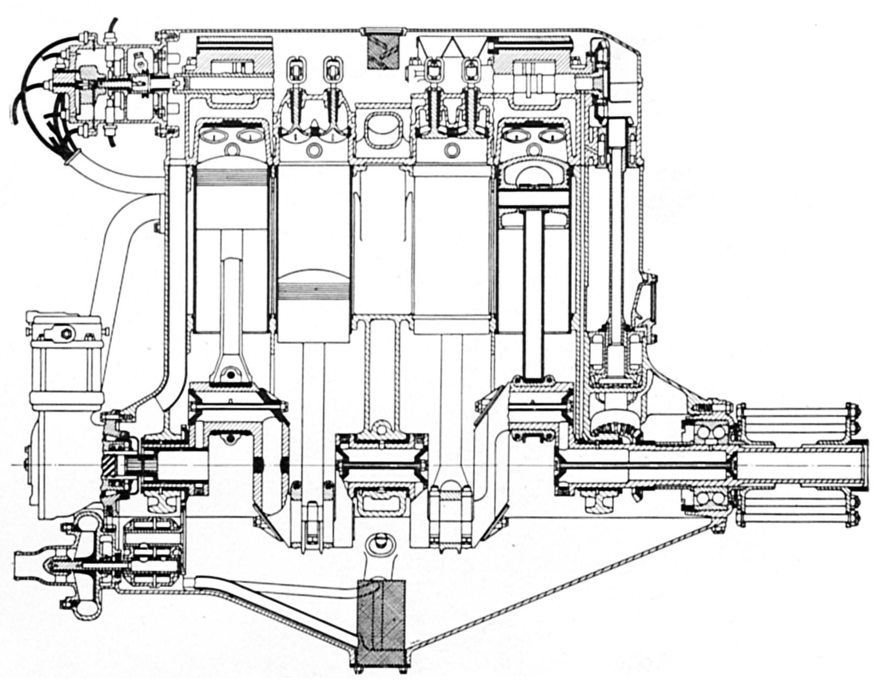
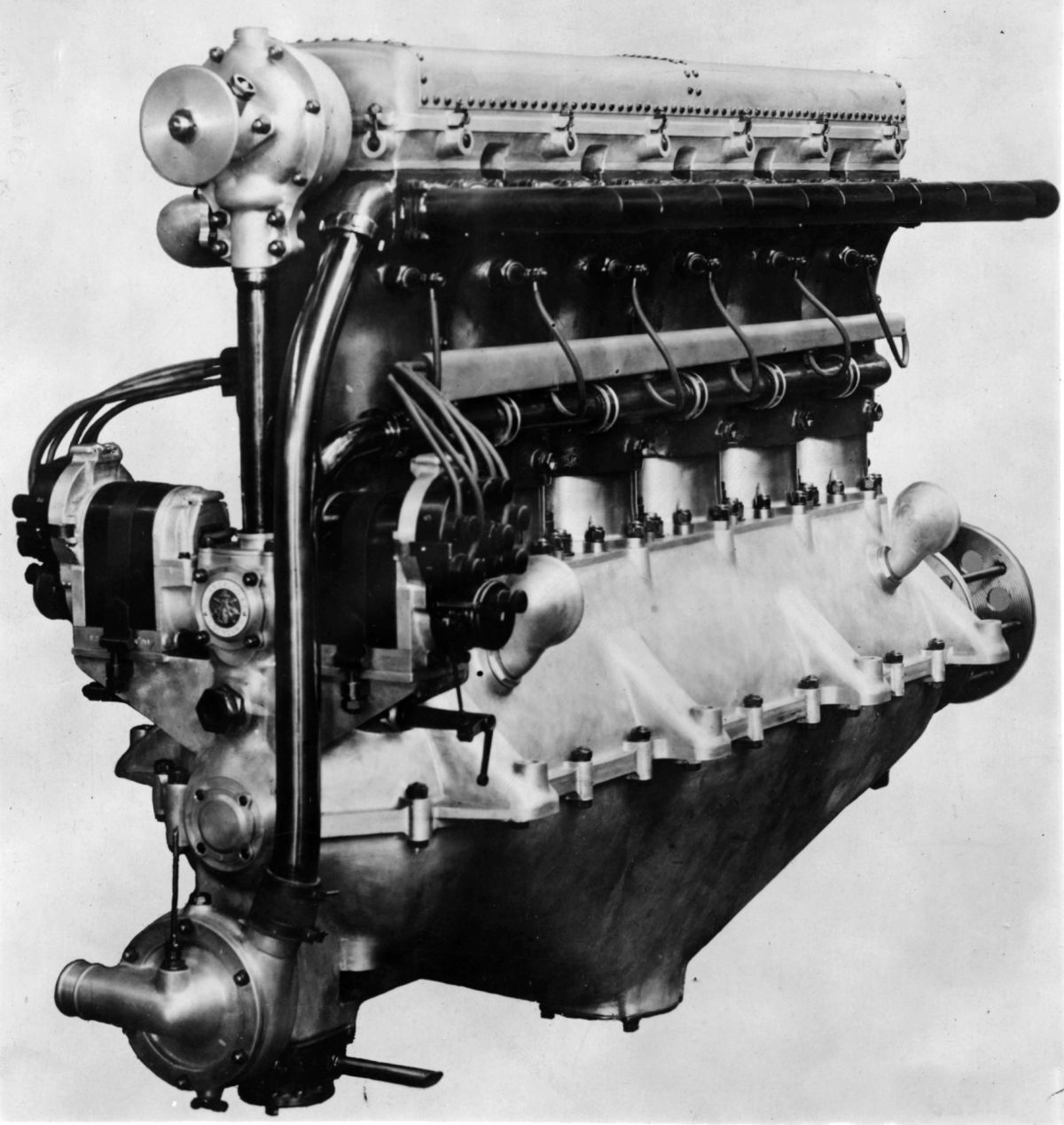
The 100-hp Aeromarine water-cooled V-8 delivered its rated output at 2,300 rpm. It featured a 3.500" bore, a 5.125" stroke and a 394.48 in³ displacement. The propeller reduction ratio was 1.7513:1, although the gearing was designed so a 2:1 ratio could be substituted. One duplex Zenith carburetor supplied the mixture, and an oil pressure of approximately 30 psi was maintained by a gear pump. Dual ignition was supplied by Delco equipment, which included an electric starter and generator. The aluminum cylinders, which were cast in blocks of four, had detachable heads and hardened cast-iron liners inserted into the cylinder barrels. The three-main-bearing crankshaft employed fork-and-blade H-section connecting rods. The aluminum pistons used three rings, two located above the piston-pin and one below serving as an oil scraper. The engine dry weight, including starter and generator, was 450 lb., or 4.5 lb/hp.
 |
 |
| Aeromarine 160hp from 1915 (NARA) | |
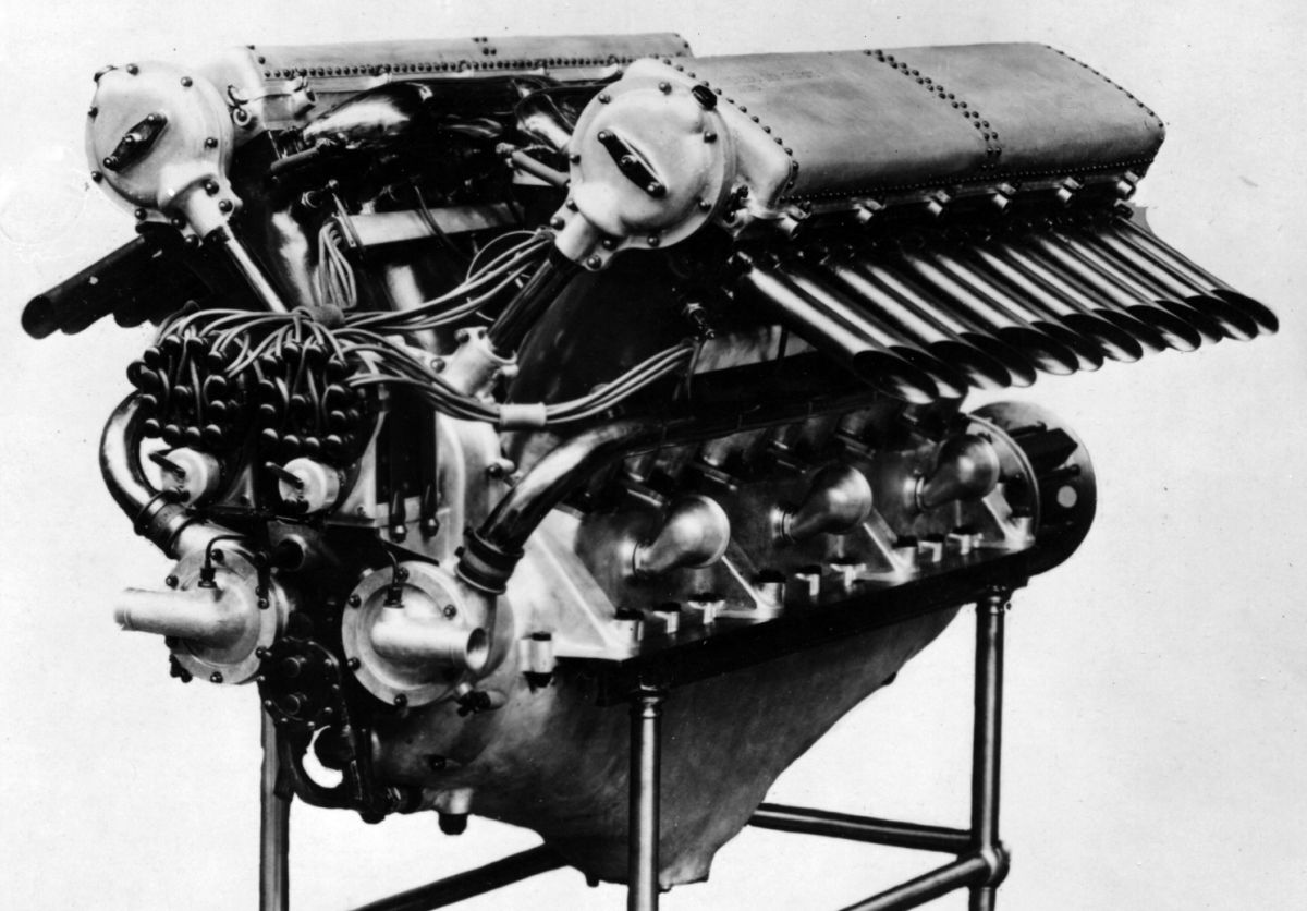
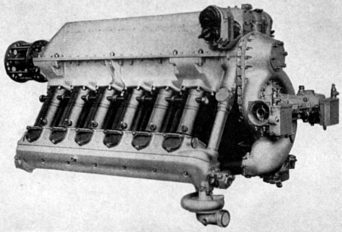
The Aeromarine D-12 produced 150 hp at 1,400 rpm This engine was a Vee type with twelve cylinders identical to those used on the 90 and l00-hp models; it displaced 898.32 in³. Dual ignition was supplied by two six-cylinder Dixie magnetos, and the dry weight was 750 lb, or 5 lb/hp.
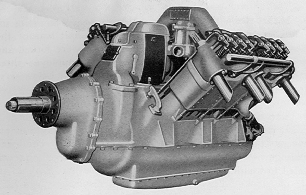
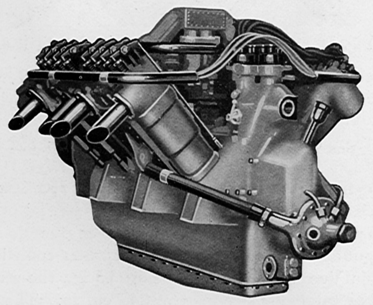
The Aeromarine Type B 90° V, with eight cylinders arranged in a 90° Vee, developed 148 hp at 2,275 rpm and 166 hp at the 2,635 maximum rpm. Its bore was 3.625", its stroke 5.125" and its displacement was 423.2 in³. The compression ratio was 5:1 and the normal bmep 120 psi. The propeller reduction ratio was 1.7513:1 with the propeller shaft being mounted on two tapered roller bearings capable of taking end thrust in either direction. Cylinders were cast in blocks of four from iron with integral barrels and combustion chambers. There were two inlet and two exhaust valves per cylinder, all with 1.375" clear diameter. These were operated through single rocker arms for each valve pair and two overhead camshafts enclosed in oil-tight housings. The three-main-bearing crankshaft had a ball bearing mounted at the center and one just outside the drive gear. The fork-and-blade connecting rods had H-section shanks. Floating piston pins were used in aluminum pistons with two top compression rings and one lower oil scraper ring. The gas mixture was supplied by a 1.75" duplex Zenith carburetor. Pressure lubrication was maintained by a three-geared duplex pump, one delivering into a high-pressure line to the crankshaft bearings, another into a low-pressure line to the camshaft, and a third circulating oil through the radiator and the oil reservoir. A centrifugal pump with two outlets delivered water at about 38 gpm to the cooling jackets. As a means of assisting fuel vaporization, some water from the cylinder water jacket tops circulated through the jacketed intake manifold. Dual ignition was furnished by Dixie magnetos. Dry weight was 460 lb, or 3.1 lb/hp.
 |
 |
 |
 |
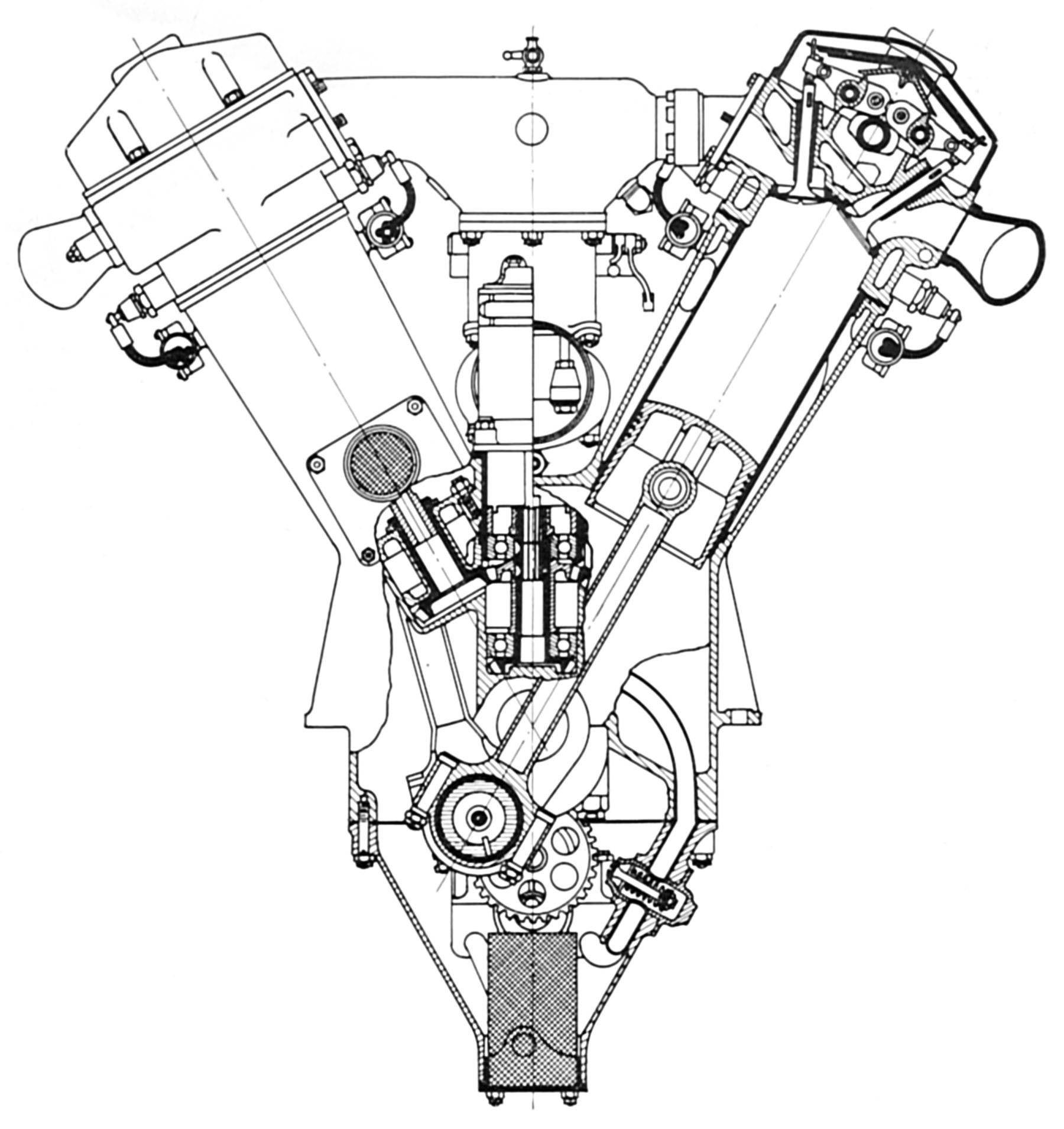
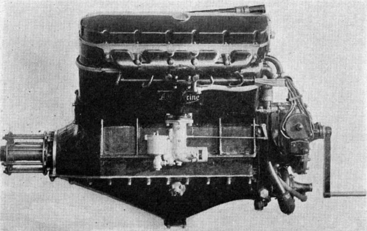
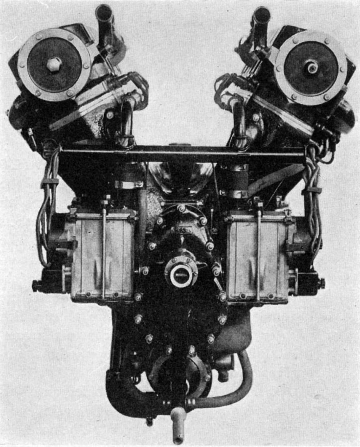
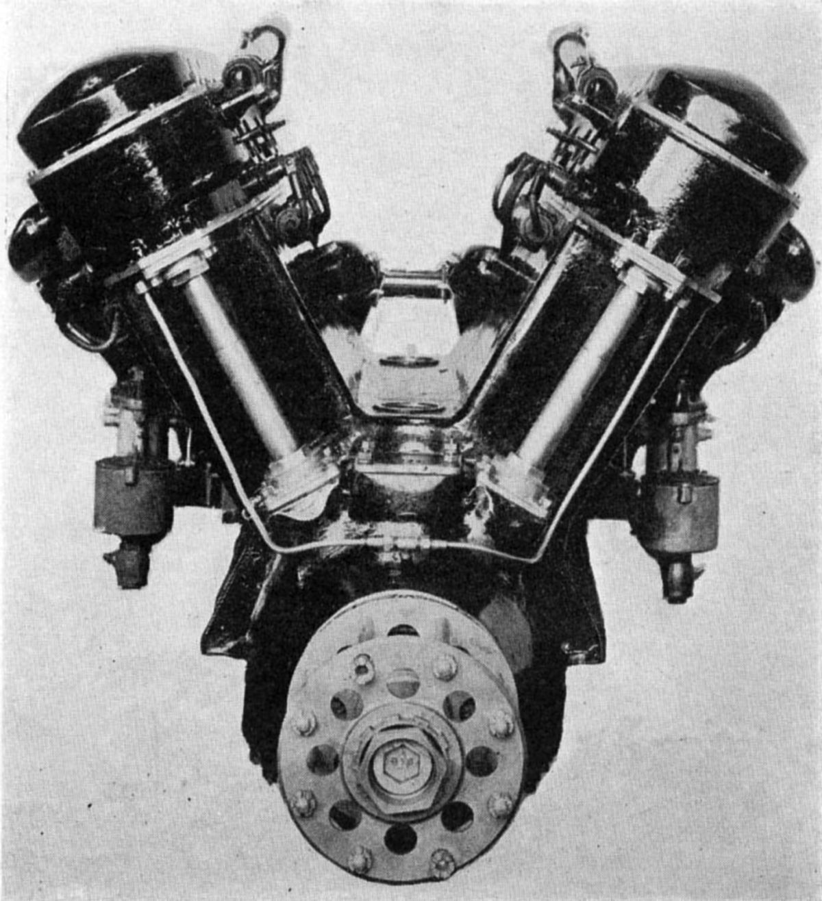
| Aeromarine Type B 90° (AEE) | Aeromarine Type B 45° (AEE) | ||
The Aeromarine Type B 45° V had eight cylinders whose dimensions corresponded with those of the Type B 90° V. The 45° V developed 150 hp at 2,275 rpm and 170 hp at 2,635 rpm. Its compression ratio was 5:1 and bmep was 121 psi. Propeller reduction ratio was 1.7513:1. The cylinders were cast in blocks of four from aluminum. Articulated connecting rods with tubular shank sections were used. The engine employed dual ignition furnished by either a Delco battery system or Dixie 800 magnetos. Dry weight was 420 lb, or 2.8 lb/hp. It was 49.688" long, 22.375" wide and 36.875" high.
 |
 |
| Aeromarine L-6 (AEE) | Aeromarine L-6-D (AEE) |
The Aeromarine Model L-6 was a six-cylinder vertical water-cooled engine developing 130 hp at 1,625 rpm, 195 hp at 1,700 rpm, and 215 hp at 3,000 rpm. With a 4.25" bore, 6.5" stroke and 553.25 in³ displacement, its compression ratio was 5.25:1 and its bmep was 122 psi at 1,700 rpm. The Model L-6 was available as a direct drive Model L-6-D or a geared Model L-6-G with a 1:869:1 propeller reduction ratio. Fuel consumption was 0.5 lb/hp/hr, and oil consumption 0.3 lb/hp/hr. Duplex Stromberg carburetors furnished the mixture, and an oil pressure of 50 psi was maintained by a gear pump. This engine was available with either a dry or wet sump system. The crankcase and cylinder water jackets were monoblock aluminum castings. A wet steel cylinder sleeve was inserted from the top, and it had an annular packing ring near its lower end to ensure a water-tight seal. Each cylinder had two inlet and two exhaust valves operated through rockers from an enclosed overhead camshaft. One flat multiple-leaf valve spring served both the inlet and exhaust valves, which were located directly opposite one another. The inlet had a clear diameter of 1.750" and the exhaust 1.656"; both valves had 30° seats and a lift of 0.469". The inlet opened 6° late and closed 42° late; the exhaust opened 46° early and closed 10° late. The firing order was 1-5-3-6-2-4. The three-main-bearing crankshaft had an additional bearing at the propeller end. The geared engine had a counterbalanced crankshaft. The connecting rods had tubular shank sections and used four bolts to secure the big end caps. The pistons were made from aluminum alloy and fitted with three compression rings and one oil-scraper ring. Dual ignition could he supplied by either a battery system or magnetos. The Model L-6-D dry weight was 400 lb, or 2.76 lb/hp. The Model L-6-G with starter and generator weighed 490 lb, and was 59" long, 16" wide and 36.5" high.
 |
 |
| Aeromarine L-8 Sections (AEE) | |
The Aeromarine Model L-8 had cylinder dimensions identical to the L-6 models (4.25" bore, 6.5" stroke) and generally followed the L-6 design. Eight cylinders were arranged in a 60° Vee and the engine developed 192 hp at 1,750 rpm from a 737.67 in³ displacement and 117.6 psi bmep. At its normal rating, fuel consumption was 0.474 lb/hp/hr and its oil consumption 0.0315 lb/hp/hr. The fork-and-blade connecting rods had tubular shank sections. Dual ignition was supplied either Delco distributors mounted on the camshaft ends or by two magnetos. Dry weight was 556.5 lb, or 2.9 lb/hp. The engine was 49" long, 32.688" wide and 34.25" high. L-8 models were available as either the direct-drive L-8-D or geared L-8-G with a 1.869:1 propeller reduction ratio.
The Aeromarine Model U-6-D was an improved L-6 model with the same 4.25" bore, 6.5" stroke, and 553.25 in³ displacement. It developed 147 hp at 1,750 rpm with a 5.3:1 compression ratio, 130 psi bmep, 0.492 lb/hp/hr fuel consumption and 480 lb dry weight. It produced 160 hp with a 7:1 compression ratio. Each cylinder featured two inlet and two exhaust valves, each with a 1.65" diameter, 30° seats, and 0.47" lift. The crankcase and cylinder water jacket were a single aluminum casting as in the L-6 model. Inserted wet steel cylinder barrels were sealed at the bottom with cork gaskets, and with copper/asbestos gaskets at the top. The removable cylinder head contained the overhead camshaft and rocker mechanism in conjunction with the characteristic Aeromarine flat-leaf valve spring, all of which were enclosed and formed and compact streamlined unit. Splitdorf magnetos supplied ignition.
The Aeromarine Model U-8-D was an eight-cylinder companion to the U-6-D and an improved design over the L-8. The bore and stroke remained 4.25" x, 6.50", with most parts interchangeable with the U-6-D. The two rows of four-cylinders were arranged in a 60° Vee. With a compression ratio of 5.45:1 and 135 psi bmep, it developed 228 hp at 1,800 rpm, and 241 hp with a 6.5:1 compression ratio. Fuel consumption was 0.471 lb/hp/hr and the dry weight was 577 lb. The cylinder, crankcase and cylinder head construction was similar to the U-6-D. Tubular-shank fork-and-blade connecting rods were machined all over. The camshafts were driven through bevel gears from vertical shafts located at the engine's propeller end. Either a Delco battery unit or Splitdorf magnetos supplied ignition. This engine was the first to pass a 300-hour endurance test conducted by the U. S. Navy.
 |
 |
 |
 |
| Aeromarine U-8-D (A39) | Aeromarine U-873 (A39) | ||
The Aeromarine U-873, a later development of the U-6-D, was produced during 1923. It featured a 4.625" bore, a 6.500" stroke, and a 873 in³ displacement. With a 5.35:1 compression ratio and 130 psi bmep, it produced 257 hp at 1,800 rpm. With a 6.35:1 compression ratio it produced 299 hp at 2,000 rpm. Fuel consumption ranged from 0.46 to 0.49 lb/hp/hr and the dry weight was 500 lb. A soft aluminum ring replaced the copper/asbestos ring at the cylinder head joint. The crankshaft was strengthened and minor structural changes helped reduce weight. It was 51" long, 32" wide and 32" high
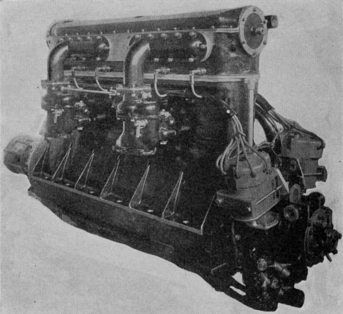 |
| T-6 (A39) |
The Aeromarine Model T-6 was a six-cylinder vertical water-cooled engine rated for 200 hp at 1,650 rpm. Its bore was 5.25", stroke 6.5", and displacement 844 in³. When using a compression ratio of 5.2:1, the bmep was 114 psi and the engine delivered 250 hp at 1,800 rpm; its dry weight was 587 lb. The T-6 was quite similar in appearance and construction to the U-6-D. Although the valve mechanism was similar, only one inlet and one exhaust valve, each 2.87" diameter were used in each cylinder. The valve stems were drilled and a tight fitting aluminum plug inserted to carry away the heat from the valve head. A one-piece removable cylinder head with soft aluminum sealing rings as employed. Magnetos furnished the ignition. It was 63" long, 19.5" wide and 36.5" high.
The Aeromarine Model S-12 was a staggered 12-cylinder water-cooled engine built in 1924. The cylinders were arranged in four banks of three each to reduce length and weight. The bore was 6.25", the stroke 6.50", and the displacement 2,390 in³. It delivered 622 hp at 1,650 rpm and 125 psi bmep. At 2,000 rpm it developed 754 hp. Compression ratio was 6:1, and the dry weight 1,050 lb. The S-12 construction followed the T-6 and closely; the crankcase and cylinder water jackets were cast in one piece. The engine was equipped with primary and secondary vibration dampers, and could be supplied with propeller reduction gears if required. Four Stromberg carburetors and two Splitdorf magnetos were used. It was 70" long, 37.75" wide and 40.5" high.
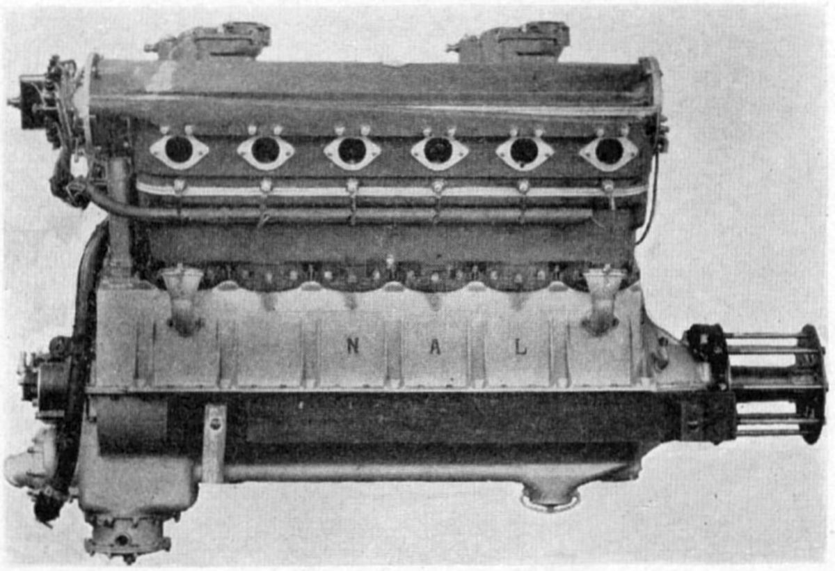 |
| Aeromarine N.A.L. (A39) |
The Aeromarine Model N.A.L was in reality a "Liberty" with Aeromarine type cylinders and valve mechanism. It was a 12-cylinder 45° Vee type water-cooled engine with a 5.000" bore, 7.000" stroke, and 1,650 in³ displacement that produced 450 hp at1,650 rpm for a 120-psi bmep. The compression ratio was 5.4:1, the fuel consumption 0.492 lb/hp/hr, and the dry weight was 900 lb. It was 70" long, 30" wide and 45" high.
 |
 |
| Aeromarine B-6 (A39) | |
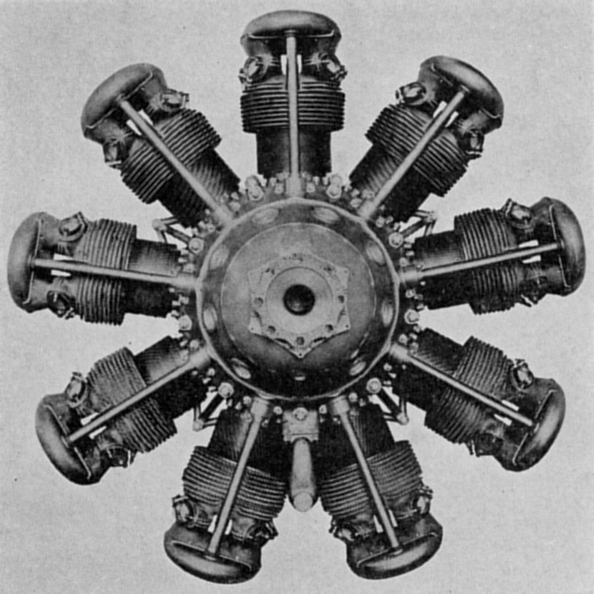
The Model B-9, a nine-cylinder air-cooled radial was developed during 1929, granted Department of Commerce Approved Type Certificate No. 41 on 11 Jan 1930, but never entered production. This engine produced 115 hp at 1,925 rpm. Its bore was 3.875", stroke 4.750" and the displacement 500 in³. The compression ratio was 4.76:1, and the dry weight 310 lb. The engine was 38" in diameter and 31" long. Fuel consumption was 0.50 lb/hp/hr and oil consumption was 0.004 lb/hp/hr. The crankshaft was built up from two pieces. Cast-iron cylinders with integral cooling fins were held to the crankcase by eight studs, and the hemispherical combustion had four inclined valves actuated by two push rods. Valve timing could be changed while the engine was in operation. The aluminum-alloy crankcase was joined in the cylinder plane and secured by nine long bolts that passed between the cylinders. A gear type oil pump provided pressure lubrication and two Scintilla magnetos furnished dual ignition.
 |
 |
| Aeromarine AR-3 (A39) | |
The Model AR-3, a three-cylinder air-cooled radial produced 50 hp at 2,125 rpm. This engine was displayed at the Detroit Aircraft Show during April 1931. It received Approved Type Certificate No. 74 on 28 Jul 1931. It weighed 150 lb, was 34.25" in diameter and 23.938" long. With a 4.125" bore and 4.000" stroke it displaced 160 in³. Mixture was furnished by a Stromberg carburetor, and dual ignition by two Bosch magnetos. Cylinders were of composite construction, with heat-treated aluminum-alloy cylinder heads featuring hemispherical combustion chambers being screwed and shrunk onto steel barrels, which had integral cooling fins. The two silchrome steel valves were inclined in the cylinder head and seated on aluminum-bronze inserts. The valves were operated through fully enclosed push rods and rocker arms from a single cam ring located forward. The cam floated on the hub of its drive gear and could be timed through the thrust bearing cover opening. The intermediate cam gear was assembled in the forward crankcase section along with the tappet guides and tappets, which used roller followers.
The AR-3 crankcase was formed by two aluminum-alloy castings joined in the cylinder plane. Besides the cam mechanism, the front section also contained a ball thrust bearing. The rear section contained a cored passage for the inlet manifold, and attached to it was a plate that carried the oil pump, magneto brackets and other accessory provisions. A mounting ring directly behind the cylinders was attached via the six main crankcase bolts. The aluminum pistons were cast in permanent moulds and featured ribs underneath the head. Two compression and two oil scraper rings were fitted to each piston. Piston-pins were full-floating, with pin end movement limited by two wire snap rings in the piston pin boss. The crankshaft was built up from two forged steel sections clamped together at the rear cheek. The crankshaft was carried on three ball bearings with the forward one a thrust bearing. The plain white-metal-lined rear journal bearing provided a means to force oil into the hollow crankshaft from the gear type oil pump. Two gears were keyed to the crankshaft - the spur cam drive gear in front, and a bevel gear that drove the rear accessories. The articulated connecting rod assembly consisted of a one-piece master rod and two link rods, all of which had tubular shanks. The crankpin bearing was a white-metal-lined bushing that were pressed into the master rod big end and a bronze bushing for the piston pin. The knuckle pins were pressed and secured into master rod flanges, and the link rods had bronze bushings at each end. The engine had provision for mounting a standard starter, and a generator could be adapted to the mounting provided above the magneto drives.
The Aeromarine AR-340 engine was granted Department of Commerce Approved Type Certificate No. 119 on December 27, 1933. It produced 40 hp at 2,050 rpm when operated on 73-octane fuel. Dry weight was 141 lb.
The Aeromarine AR-3 and AR-340 engine names were changed to the Burnelli AR-3 and Burnelli AR-340 to reflect new type certificate ownership by the Burnelli Aircraft, Ltd., another I. M. Uppercu company that absorbed Aeromarine. Later, in early 1938, the AR-3 engine became known as the Lenape "Papoose" when the engine business was acquired by Lenape Aircraft & Motors, Inc. of New York City.
Ansaldo
The Italian Ansaldo San Giorgio Company was founded in 1853 by several influential Genoese businessmen including Giovanni Ansaldo. The company initially manufactured railway components, then branched out into shipbuilding and aircraft. It began building aircraft engines during WWI by first constructing the Spa 6-A. In 1917, Ansalado started building its own engine designs.
The Type 4-E. 145 was a twelve-cylinder water cooled engine producing 290 hp at 1,650 rpm, and 310 hp at 1,800 rpm. It had a 145 mm (5.709") bore, a 180 mm (7.087") stroke and displaced 17.83 l (1,088 in³). Fuel consumption was 0.473 – 0.489 lb/hp/hr and bmep was 129 psi. Two Zenith carburetors each fed three cylinders. Pressure lubrication was maintained by gear pumps, and two six-cylinder magnetos furnished dual ignition. The individual steel cylinders had welded sheet-metal water jackets, and were fitted with two inlet and two exhaust valves operated by an overhead camshaft. The connecting rods had tubular shank sections, and the pistons were made from aluminum. Dry weight was 639 lb, or 2.13 lb/hp.
The Type 4-E. 150 was another six-cylinder vertical water-cooled engine producing 300 hp at 1,700 rpm.
 |
 |
 |
| Ansalado 4-E. 145 (NARA) | Ansalado 4-E. 150 (NARA) | |
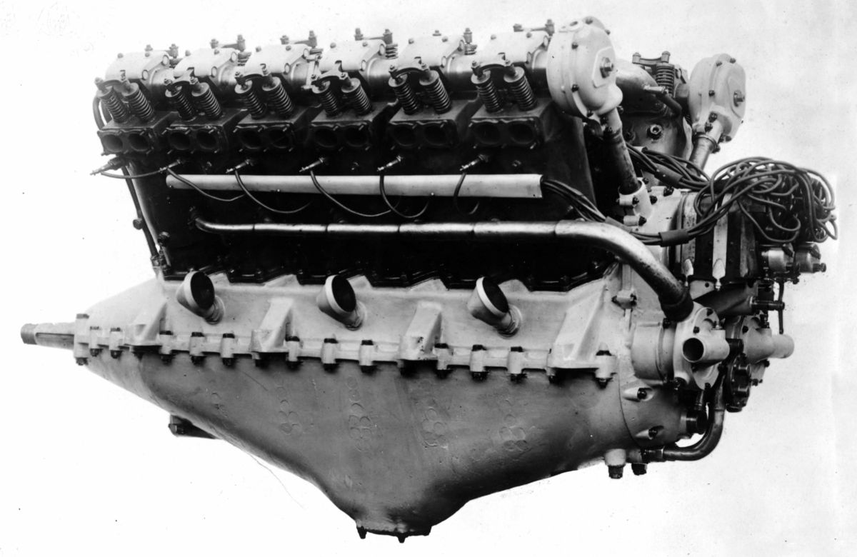
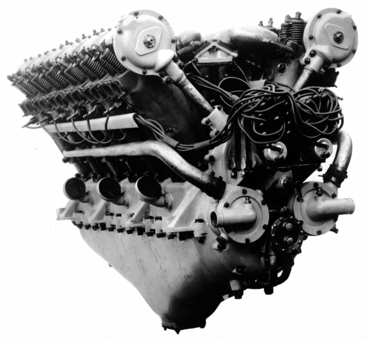
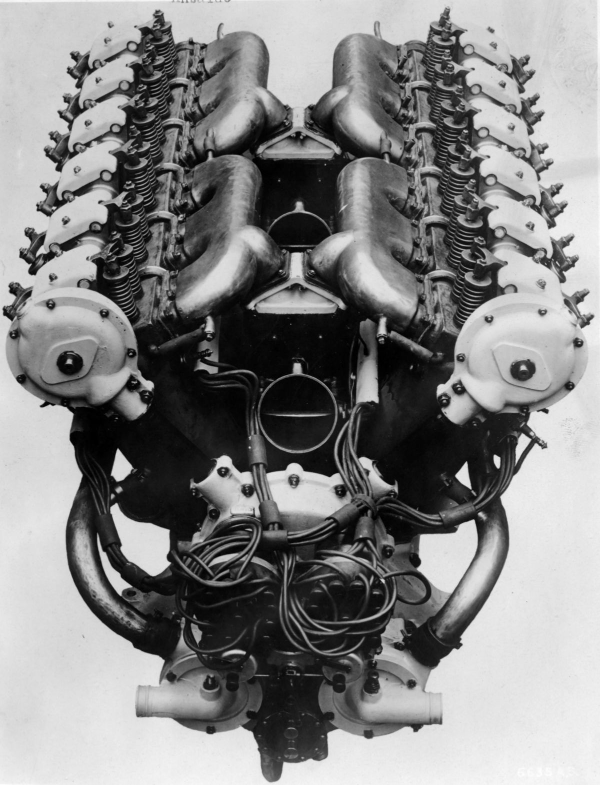
The Type 4-E. 284 was a twelve-cylinder 60° water-cooled Vee type with a 140 mm (5.512") bore, a 180 mm (7.087") stroke and a 32.25 l (1,968 in³) displacement. It was rated at 450 hp and produced 520 hp at 1,650 rpm and 123 psi bmep. Individual steel cylinders had welded-on water jackets. Two inlet and two exhaust valves per cylinder were operated from two overhead camshafts. Articulated connecting rods were used Fuel consumption ranged from 0.473 to 0.484 lb/hp/hr and oil consumption ranged from 0.022 to 0.033 lb/hp/hr. The two Zenith carburetors, located within the Vee, each supplied six cylinders. Pressure lubrication was maintained by a gear pump and wet-sump oil reservoir. Two magnetos each supplied six cylinders. The dry weight was 1,125 lb, or 2.5 lb/hp.
The Type 4-E. 29 was a twelve-cylinder Vee type water-cooled engine producing 550 hp at 1,650 rpm.
 |
 |
 |
 |
| Ansalado 4-E. 284 (NARA) | Ansalado 4-E. 29 (NARA) | ||
Antoinette
Léon Levavasseur (8 Jan 1863 - 26 Feb 1922) was a French inventor and designer of aircraft engines. In 1902 he approached his friend Jules Gastambide, owner of an Algerian power station, with the idea of building engines suitable for aircraft propulsion. Gastambide financed Levavasseur's engine development efforts, which resulted in a V-8 aircraft engine patent, along with designs for several other engines. Gastambide founded La Société Antoinette in 1906, naming the company after his daughter. Gastambide was president, Levavasseur the technical director, and Louis Blériot vice-president.
Antionette sold engines to aircraft builders, including Santos-Dumont for his 1906 14-bis of 1906, Paul Cornu for his 1907 helicopter, and Henri Farman for the Voisin biplane in which he made the first European one-kilometer circular flight.
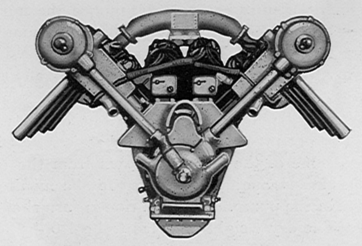
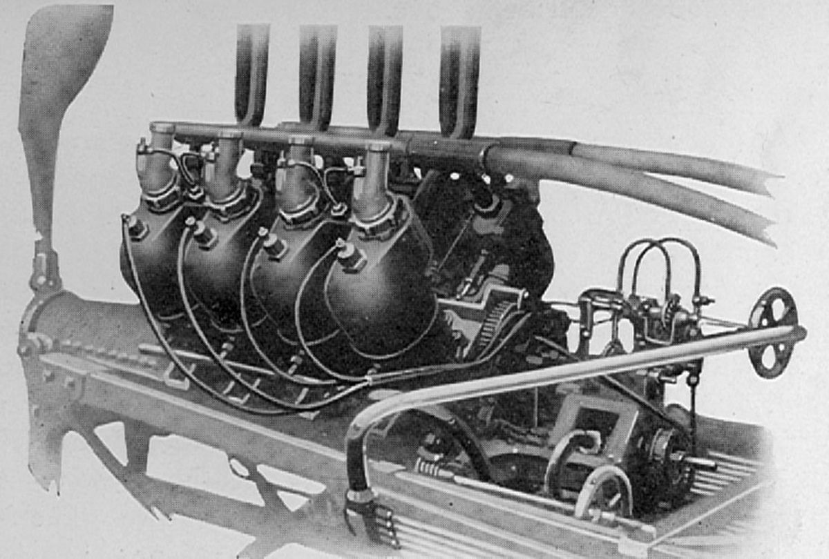
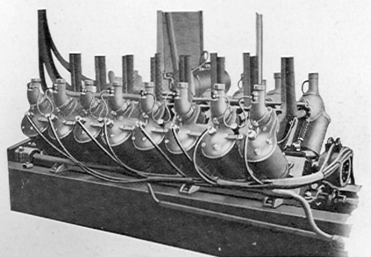
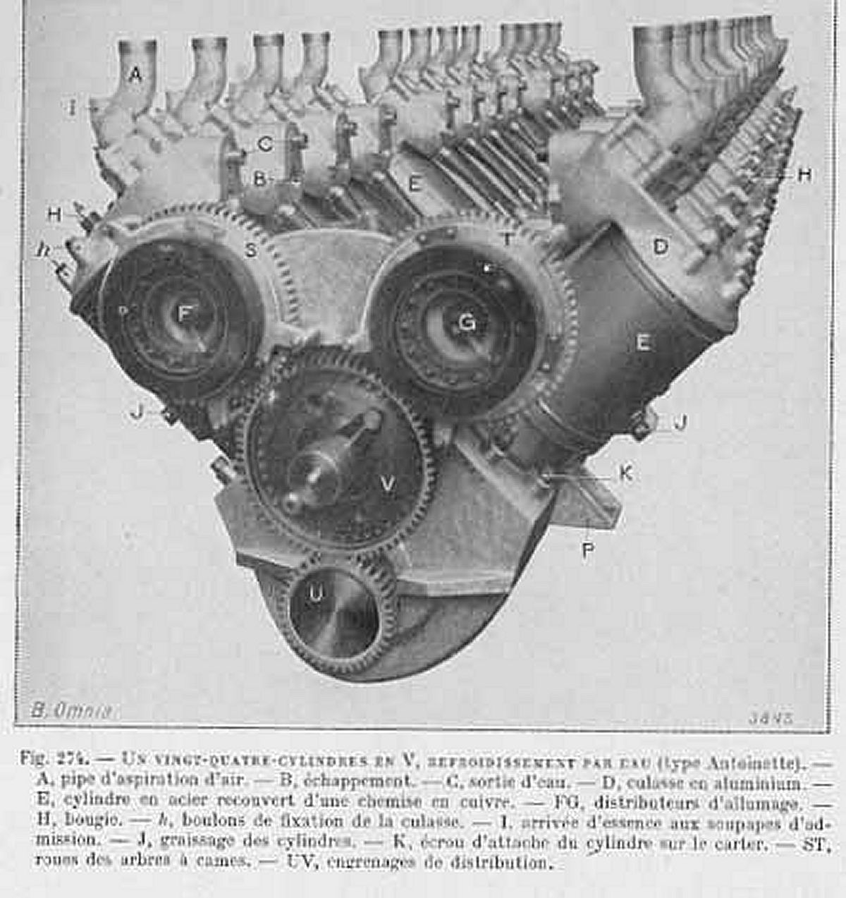
Levavasseur's eight, sixteen, and thirty-two cylinder water-cooled Vee-type engines replaced traditional carburetors with fuel injection systems using plunger pumps operated by variable-throw eccentrics to inject the fuel directly into the inlet valve ports. The cooling water was boiled in the cooling jackets, condensed in a large aluminum condenser, and returned to the engine by means of a small belt-driven pump. The cylinders had drop-forged steel heads and electrolytically-deposited copper jackets. Valves were located at the combustion chamber side, with an automatic inlet valve above the cam-and-pushrod-actuated exhaust valve.
An early V-8 produced 32 hp at 1,400 rpm. With an 80mm (3.150") bore and stroke, it displaced 3.22 l (196.3 in³) and had a 92.5 psi bmep. Dry weight was reported as 93 lb, or 2.9 lb/hp. A larger V-8 produced 67 hp at 1,100 rpm. Its bore was 110 mm (4.331"), its stroke 105 mm (4.134"), and it displaced 7.98 l (487.1 in³). Bmep was 99 psi and dry weight was 209 lb, or 3.1 lb/hp. A still-later V-8 produced 55 hp.
A V-16 developing 64-hp used the same cylinder dimensions (80 x 80 mm) as the 32-hp engine and displaced 6.43 l (329.6 in³). Its dry weight was said to be 165 1b, or 2.6 lb/hp. Another V-16 with the same (110 x 105 mm) cylinder dimensions as the 67-hp V-8 developed 134 hp. Its dry weight was 264 lb, or 2 lb/hp.
 |
 |
 |
 |
 |
| Antoinette 50 hp V-8 | Antoinette 55 hp V-8 (AEE) | Antoinette 134 hp V-16 (AEE) | Levavasseur 1903 V-8 (Philippe Gervais) |
1907 V-24 (Philippe Gervais) |
William Pearce’s Outstanding Antoinette Article
Anzani
Ambrogio Alessandro Anzani (5 Dec 1877 – 23 Jul 1956) was an Italian motorcyclist, pilot, industrialist and engine designer who founded the Anzani Engine Factory in 1907. The Anzani firm became a well-known motorcycle engine builder, a legacy that is clear in its earlier engines with fan and Vee cylinder arrangements. Fears of excessive oiling when cylinders were below horizontal probably influenced the early designs. Additional experience proved that with carefully designed lubrication systems the oiling difficulties were not serious.
 |
 |
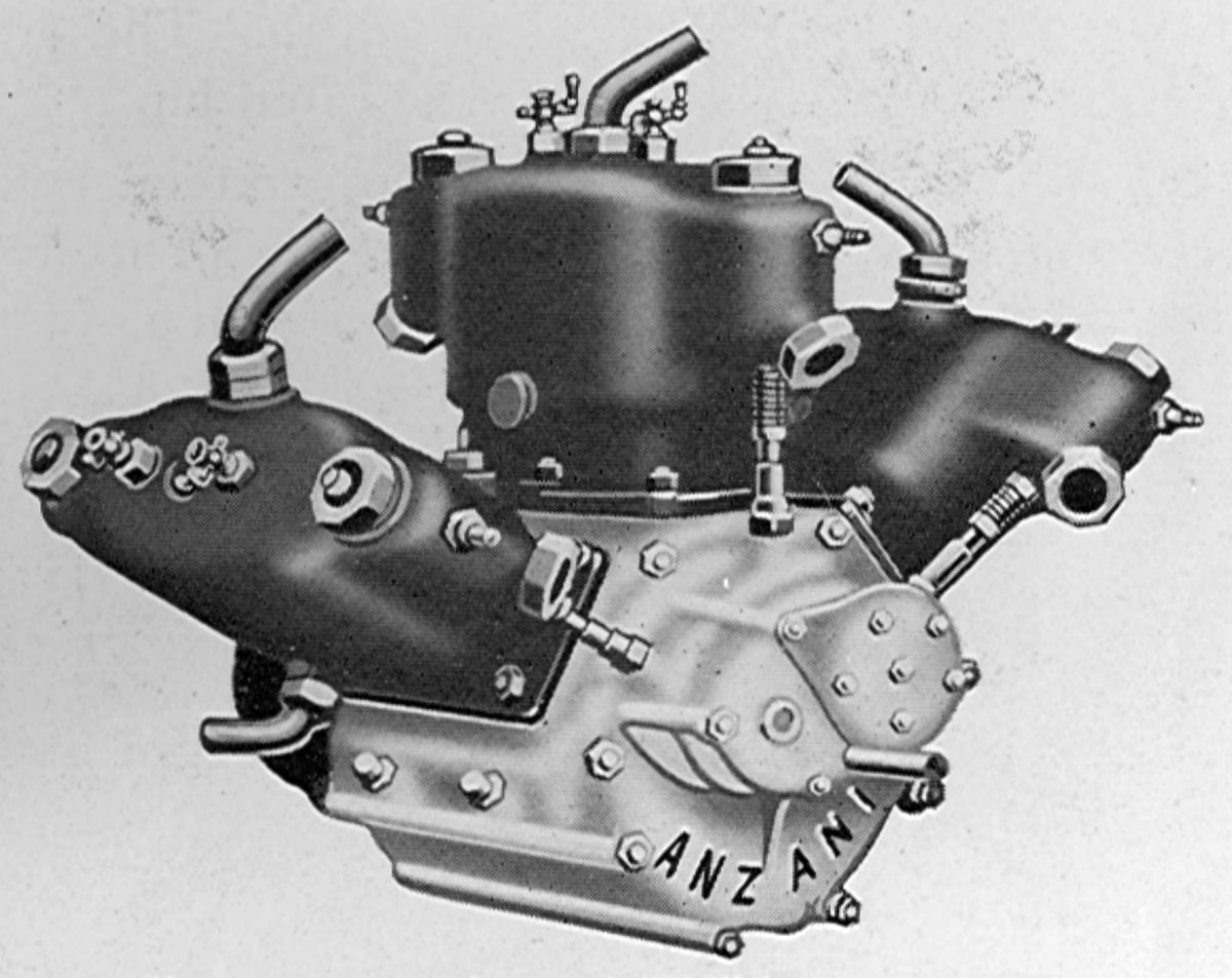
| Water-Cooled W-6 (AEE) |
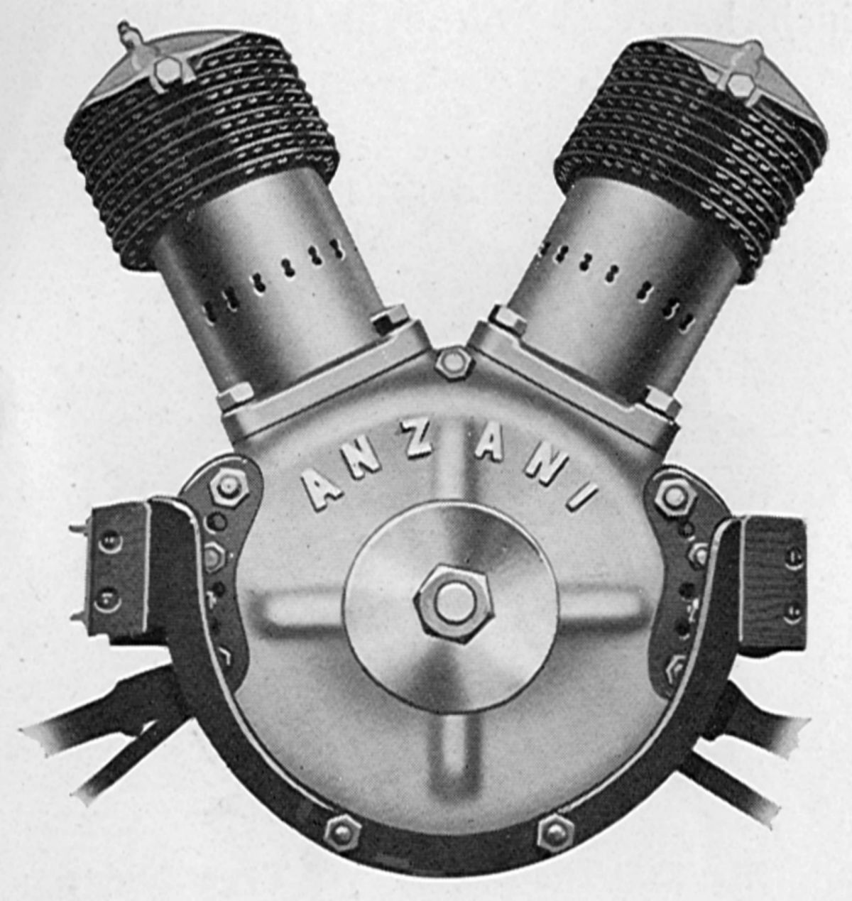
Air Cooled V-2 (AEE) |
During the years 1910 and 1912 Anzani produced two sizes of four-cylinder water-cooled Vee-type engines that had cast-iron cylinders with integral water jackets. The smaller of these engines, which produced 30 to 32 hp at l,600 rpm, had a 100 mm (3.940") bore, a 120 mm (4.724") stroke. and a 3.77 l (230.1 in³) displacement. The weight was 187 lb. The engine was 26" long, 19" wide and 26" high. The larger four-cylinder water-cooled Vee engine delivered 56 hp at 1,400 rpm The bore was 135 mm (5.315"), the stroke 150 mm (5.906"), and the displacement 8.588 l (524.1 in³) Weight was 308 lb, or 5.5 lb/hp.
The six-cylinder water-cooled "W" type Anzani engine was constructed similarly to the air-cooled fan types. The cast-iron cylinders had integral water jackets. The crankshaft had two throws, with fork-and-blade connecting rods.
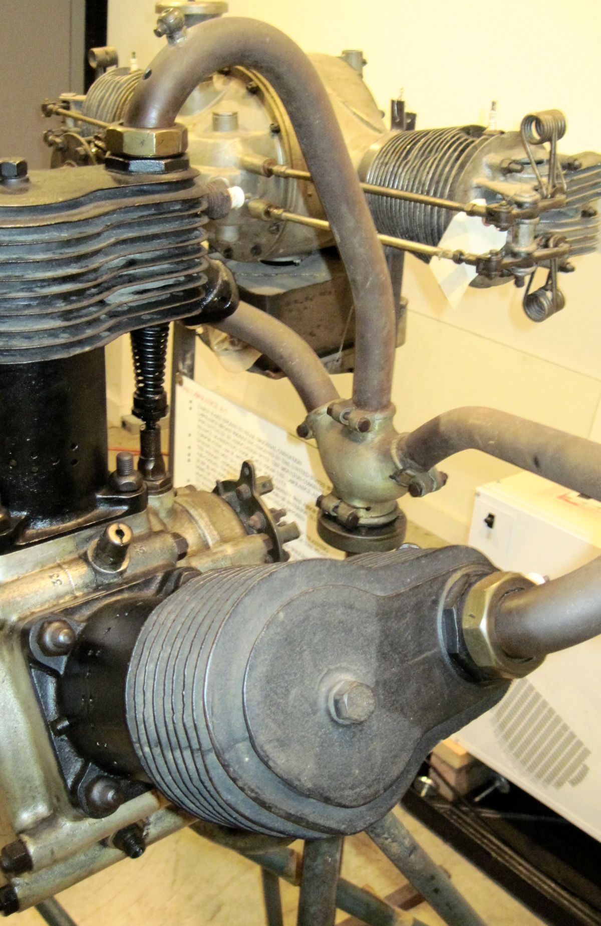
Anzani two-cylinder air-cooled Vee-type engine had cast-iron cylinders with perforated sheet metal cooling fins. Auxiliary exhaust ports located in the cylinder barrel were uncovered by the piston near the end of its stroke. Anzani built five three-cylinder air-cooled fan type models. The cylinders of these engines were made from cast iron with integral cooling fins . Valves were in a pocket at the combustion chamber side, one above the other. The uppermost inlet valve operated automatically while the exhaust valve was cam operated. The built-up crankshaft had a single crankpin connecting two discs that served as flywheels and counterweights. The crankshaft was supported on two plain bearings. The connecting rods serving the two outer cylinders were forked and straddled the plain rod big end used for the center cylinder. The angle between cylinders was 72°, which did not produce even firing intervals. The pistons were cast from iron and fitted with two compression rings above the piston-pin. Bosch magnetos provided ignition. The smaller fan-type series had a 85 mm (3.347") bore and stroke and displaced 1.447 l (88.3 in³). It was produced 14 hp at 1,800 rpm and weighed 77 lb, or 5.5 lb/hp.
When the same engine's stroke was increased to100 mm (3.937") the displacement increased to 1.702 l (103.9 in³) and it developed 15 hp at1,800 rpm; dry weight was 94 lb, or 6.27 lb/hp. Another engine with a 105 mm (4.134") bore, 130 mm (5.118") stroke and 3.377 l (230.1 in³) displacement produced 24.5 hp at 1,600 rpm and weighed 145 lb, or 5.91 lb/hp. This engine was 26" long, 36" wide and 25" high. When this engine type powered the Bleriot airplane across the English Channel in Jul 1909 it became the most famous of the three-cylinder fan types
An engine with a 120 mm (4.724") bore, 130 mm (5.118") stroke, and 4.41 l (269.2 in³) displacement produced 31.6 hp at 1,500 rpm. It weighed 176 lb, or 5.57 lb/hp. The largest three-cylinder fan-type engine had a 135 mm (5.315") bore, 150 mm (5.906") stroke, 6.441 l (393.1 in³) displacement, and delivered 42.3 hp at 1,400 rpm from 231 lb, or 5.46 lb/hp.
 |
 |
 |
| Front (Author) | Left Front (AEE) | Induction (Author) |
 |
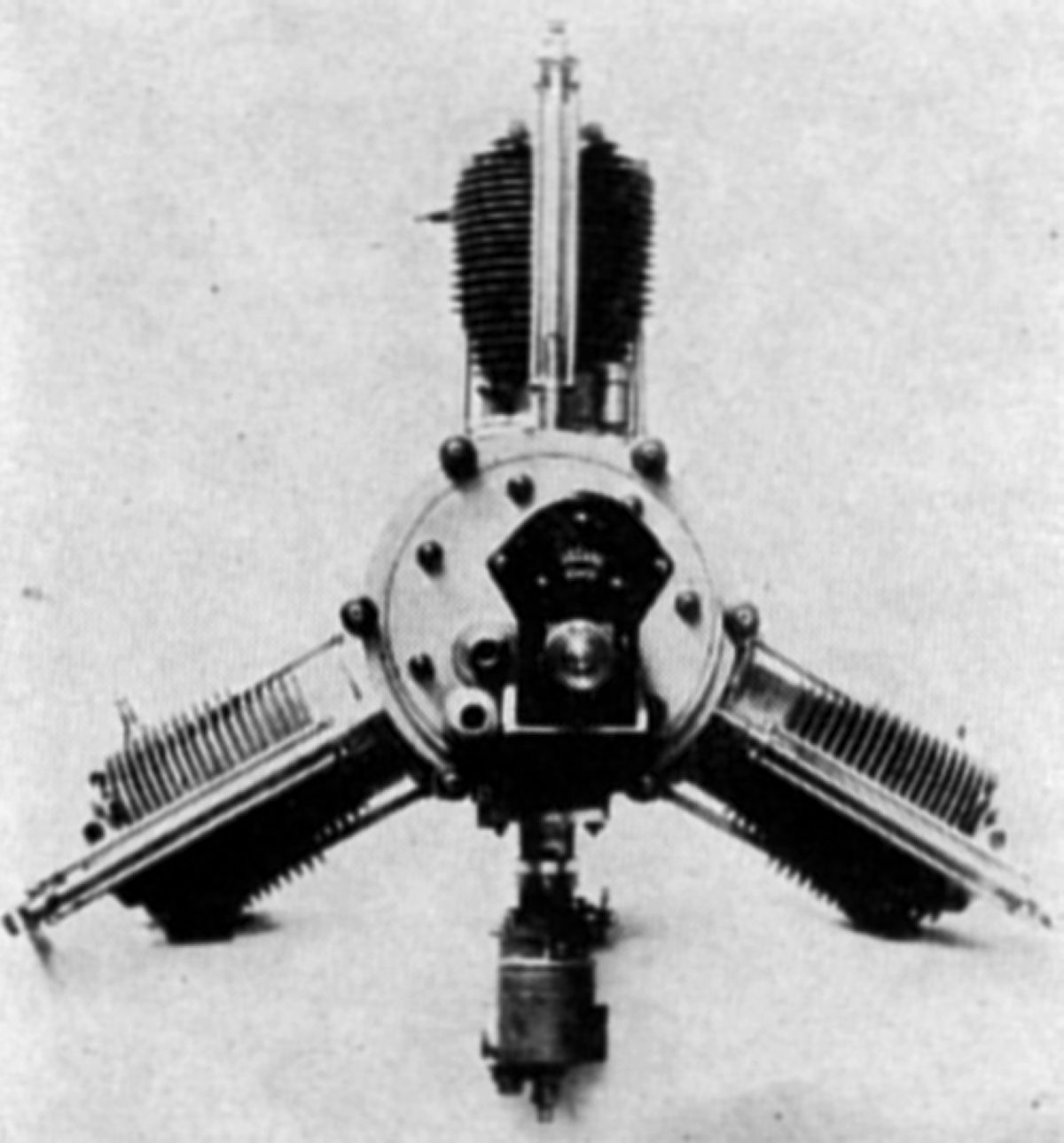 |
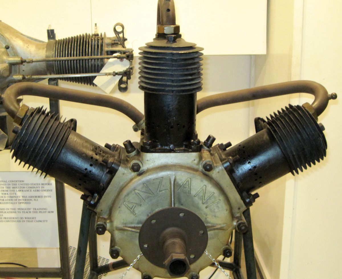
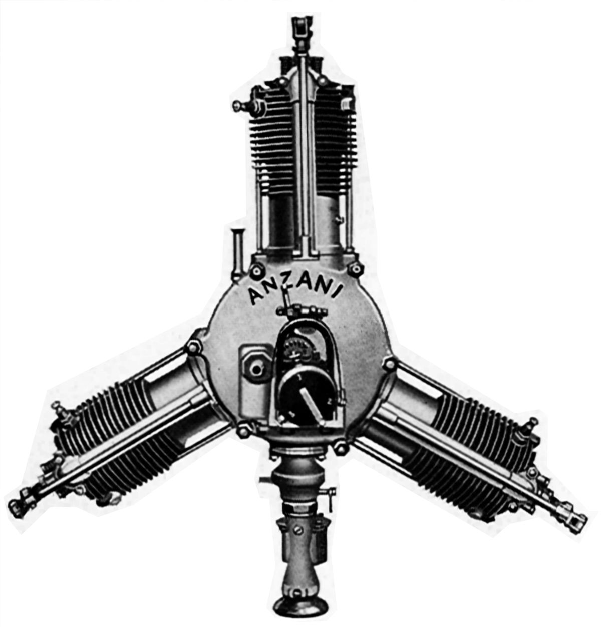
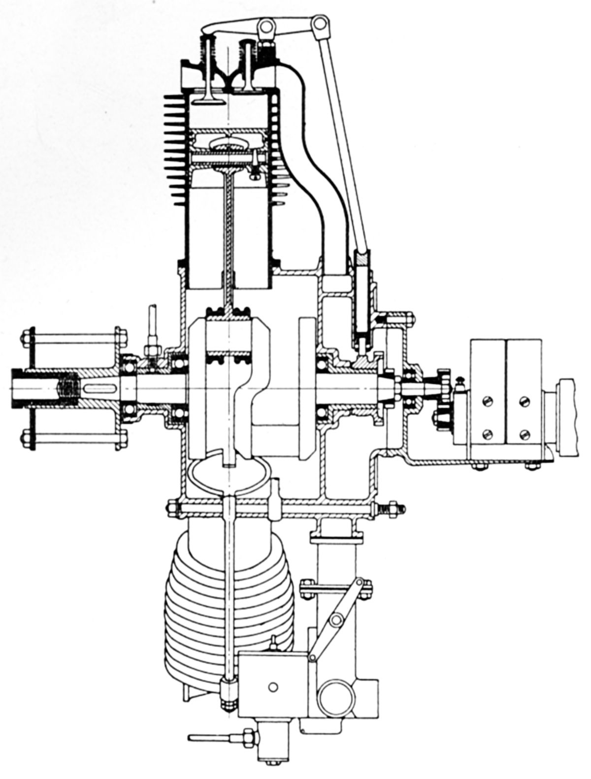
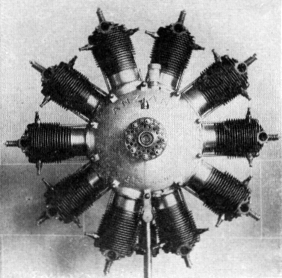
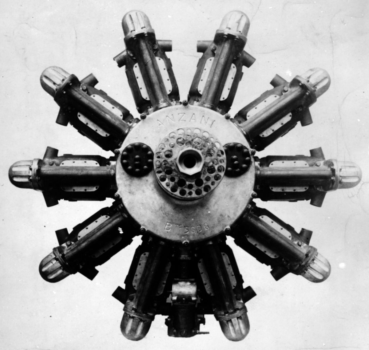
| Early Radials (AEE, A39) | |
In 1910, Anzani introduced a radial with three-cylinders spaced 120° and an even 240° firing interval. This engine had a 105 mm (4.134") bore, a 120 mm (4.724") stroke and displaced 3.117 l (190.2 in³). It developed 30 hp at 1,300 rpm for a 96 psi bmep. Fuel consumption ranged from 0.60 to 0.64 lb/hp/hr and oil consumption was approximately . 0.11 lb/hp/hr. It weighed 121 lb, or 4.03 lb/hp Except for the valve location cylinder attachment the design was similar to the fan-type engines. Another three-cylinder radial with a 100 min (3.937") bore, 120 mm (4.725") stroke, displaced 2.827 l (172.5 in³) produced 18 hp at 1200 rpm. and 24 hp at 1,500 rpm from a 143 lb weight.
A five-cylinder Anzani air-cooled radial engine design was used extensively in French flying school machines. These engines developed 40 to 50 hp and weighed 159 lb. Cylinders construction was similar to previously-described Anzani air-cooled engines. This engine's induction system consisted of a mixing chamber in the crankcase fed by one carburetor from which extended tangentially an inlet pipe to each of the five cylinders.
 |
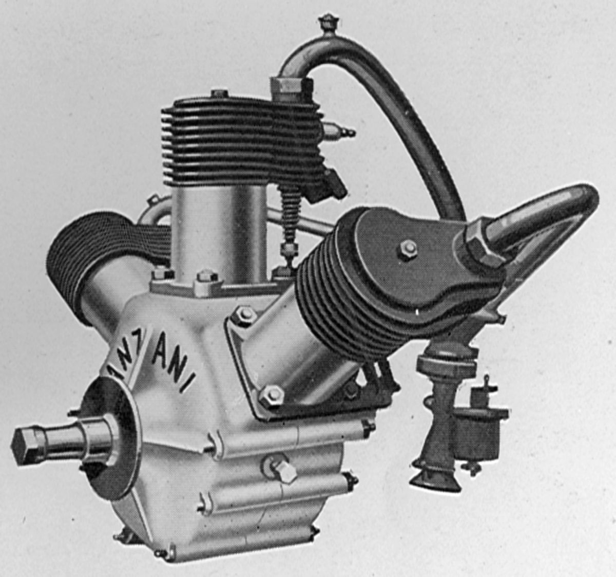
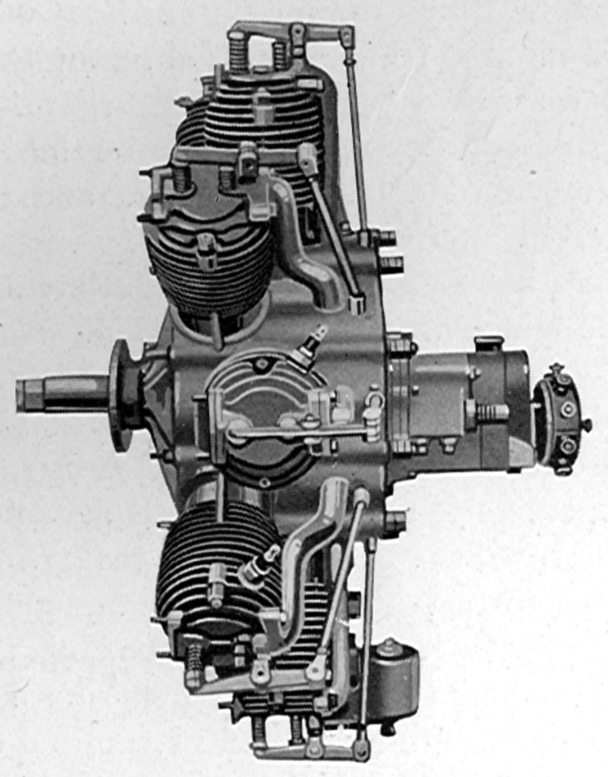
| Early 40 hp 6-Cylinder (AEE) |
Anzani six-cylinder air-cooled radial designs, which began production in 1911, consisted of two 3-cylinder rows. Cast iron cylinders with integral cooling fins were secured to the crankcase via long bolts extending to bosses at the top. Vertical overhead valves seated directly on the cylinder material. The inlet valve was automatic and the exhaust valve was operated by a pushrod and rocker arm. A two-throw counterbalanced crankshaft ran in a ball bearing in front, a plain bearing aft, and a third ball bearing at the propeller shaft for thrust and radial loads. H-section connecting rods employed slipper bearings at the crankpin end. Each bearing segment was a shoe with helical edges forming a hollow cylinder segment. Each shoe was held in place by a split bronze sleeve with a pair of bronze collars clamped together about their outer surface. The cast-iron pistons were fitted with two rings. The smaller of the six-cylinder designs had a 90 mm (3.543") bore, a 120 mm (4.725") stroke, a 5.48 l (334.4 in³) displacement and a 40 to 45 hp at 1,300 rpm rating. Fuel consumption ranged between 0.51 to 0.60 lb/hp/hr and oil consumption was approximately 0.11 lb/hp/hr. Weight was 154 lb. A larger six-cylinder radial had a 105 mm (4.134") bore, a 120 mm (4.725") stroke, a 6.234 l (380.4 in³) displacement, and a 50 to 60 hp at 1,300 rpm output. Fuel consumption ranged from 0.52 to 0.60 lb/hp/hr. Oil consumption was approximately 0.11 lb/hp/hr. Dry weight was somewhere between 176 and 200 lb.
A plethora of Anzani ten-cylinder air-cooled radial designs were the natural evolution of five-cylinder single-row engines. All had two rows of five cylinders around a two-throw crankshaft. An experimental 10-cylinder engine rated at 200 hp was envisioned.
| Power hp @ rpm |
Bore mm (") |
Stroke mm (") |
Displacement l (in³) |
BSFC lb/hp/hr |
BSOC lb/hp/hr |
Weight lb |
|---|---|---|---|---|---|---|
| 60 – 70 hp @ 1,250 | 90 (3.543) | 120 (4.274) | 7.634 (465.9) | 0.59 | 0.11 | 216 –242 |
| 80 @ 1,250 | 90 (3.543) | 130 (5.118) | 8.27 (504.6) | 0.60 | 0.11 | 225 |
| 100 @ 1,200 | 105 (4.134) | 120 (5.512) | 12.123 (739.8) | 0.60 | 0.11 | 300 |
| 95 – 100 @ 1,250 | 105 (4.134) | 145 (5.709) | 12.556 (766.2) | 0.627 | 0.128 | 363 – 384¹ |
| 125 @ 1,200 | 115 (4.528) | 150 (5.906") | 15.58 (950.7) | 0.57 | 2.3 gal/hr | 460 |
| 125 @ 1,250 | 115 (4.528) | 155 min. (6.102) | 16.1 (982.5) | 0.59 | 0.11 | 465 |
| ¹ Steel cylinders with integral cooling fins. | ||||||
 |
 |
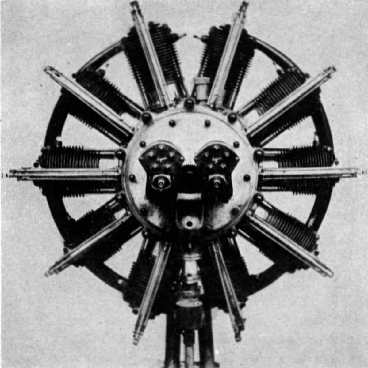 |
| Anzani 10-Cylinder Engine (AEE) | ||
An Anzani fourteen-cylinder air-cooled radial producing 150 hp at 1,100 rpm resulted from a 105 mm (4.134") bore, 140 mm (5.512") stroke and 16.972 l (1,037.7 in³) displacement. The design was similar to the ten-cylinder radial with corresponding cylinder dimensions.
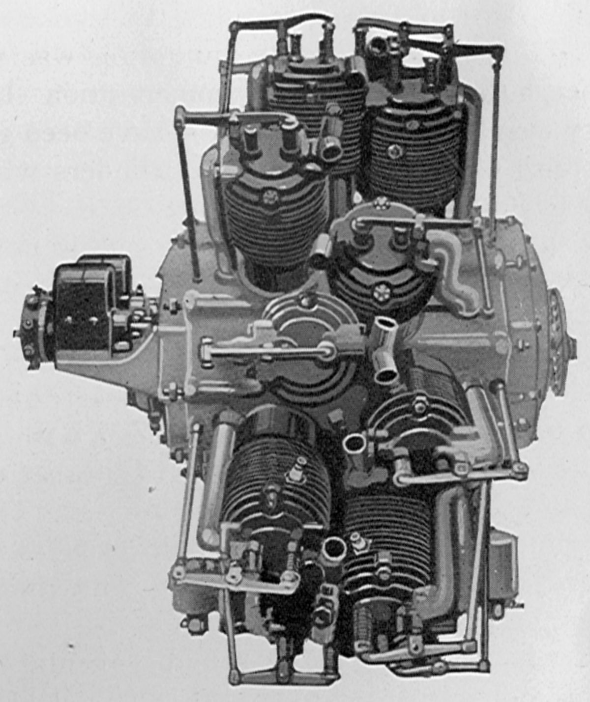 |
| Air-Cooled 20-Cylinder (AEE) |
In 1912, Anzani produced a 20-cylinder air-cooled engine with 4 rows of 5 cylinders. It had a 105 mm (4.134") bore, 140 mm (5.512") stroke, displaced 24.245 l (1,479.5 in³ and was rated 200 hp at 1,250 rpm. Specific fuel consumption was 0.50 – 0.59 lb/hp/hr and specific oil consumption was 0.11 lb/hp/hr. Dry weight was 680 lb. The four cylinder rows were arranged closely by staggering two five-cylinder connecting rod assemblies side by side on one crankpin. The two-throw crankshaft was made with an included angle of 162° between crankpins in order to produce even firing intervals. The induction system consisted fore and aft mixing chambers each fed from one carburetor. Two lubrication systems were employed, and two magnetos furnished the ignition. The exhaust valves of the first two cylinder rows were operated from the front, and those of the second two rows from the rear. The inlet valves operated automatically. Please see William Pearce's excellent article on the 20-cylinder Anzani.
 |
| Water-Cooled 20-Cylinder (AEE) |
Anzani introduced a twenty-cylinder water-cooled radial producing 640 hp at 1,240 rpm in 1920. This engine had a 140 mm (5.512") bore, 150 mm (5.906") stroke, displaced 46.181 l (2,818.1 in³) and developed 640 hp at 1,240 rpm. It weighed 1,212 lb and had a 51" diameter. This engine used two rows of ten cylinders with one row directly behind the other. The cylinders were cast in pairs from aluminum and fitted with cast-iron liners. Each cylinder pair had a common water jacket, and its own overhead camshaft driven by shaft and bevel gears. The valves were operated from cams through cups inverted over the valve spring, and they were retained in bronze guides. The exhaust valves discharged into a siamesed port at the center of the cylinder block, and the inlets were fed from individual pipes connected to a manifold at each end of the crankcase, each manifold being supplied by a separate Solex carburetor. The pipe at the front was integral with the camshaft drive shaft housing. Diametrically opposite cylinders fired at the same time, the ignition being furnished by two ten-cylinder magnetos and two ten-cylinder distributors. The crankshaft had two throws, one for each row of ten cylinders. Articulated connecting rods attached to a master rod that was split along its entire major-axis length to permit assembly. The articulated rods had integral knuckle pins that were spaced by the master rod to give an equal stroke to each cylinder.
In 1922 all Anzani engines incorporated mechanically operated inlet valves to replace the previously-used automatic ones. A new system of concentric cam followers was adopted. The outer follower acted for the inlet, its forked lower end making contact with a double inlet cam formed integral with and on each side of the exhaust cam. The valves were operated by separate push rods and rocker arms, the inlet rocker arm being located underneath the exhaust rocker. These newer models all employed cast-iron cylinders and aluminum pistons. The compression ratio was 4.5:1. The lubrication system forced measure oil quantities into the main bearings through a hollow crankshaft to the crankpin, from where it was sprayed into the engine interior to be burned. Castor oil was used, and consumed at the rate of 0.020 gal/hp/hr. From 1925 to 1927, Babbitted crankpin bearings were used.
| Power hp @ rpm |
Cylinders | Bore mm (") |
Stroke mm (") |
Displacement l (in³) |
Weight lb |
|---|---|---|---|---|---|
| 30 @ 1,800¹ | 3 | 89 (3.504) | 105 (4.134) | 1.96 (119.6) | 110 |
| 36 @ 1,600 | 3 | 105 (4.134) | 120 (4.724) | 3.117 (190.2) | 132 |
| 57 @ 1,600 | 6 | 90 (3.543) | 120 (4.724) | 4.58 (218.5) | 165 |
| 80 @ 1,550 | 6 | 105 (4.134) | 125 (4.921) | 6.494 (396.3) | 215 |
| 110 @ 1,650² | 10 | 105 (4.134) | 125 (4.921) | 10.824 (660.5) | 300 |
| 110 @ 1,400 | 10 | 105 (4.134) | 145 (5.709) | 12.556 (766.2) | 320 |
| ¹Compression Ratio = 5.5:1 ²One-Piece Crankcase | |||||
Starting in 1927, Henry Lowe Brownback, an American engineer, collaborated with Anzani to distribute engines in the U.S. as well as in engineering new engines using air-cooled principles pioneered by Anzani. Brownback introduced full-floating piston pins with aluminum end buttons, an improved aluminum alloy piston, a compression ratio increase to 5:1, full pressure lubrication with pressure and scavenge pumps, dual ignition, and increased valve size now operated by side-by-side cam tracks actuating roller followers and push rods. Rocker arms were heavier and their supports were forged steel with stud attachment to the cylinders.
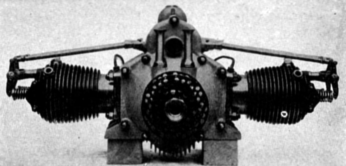
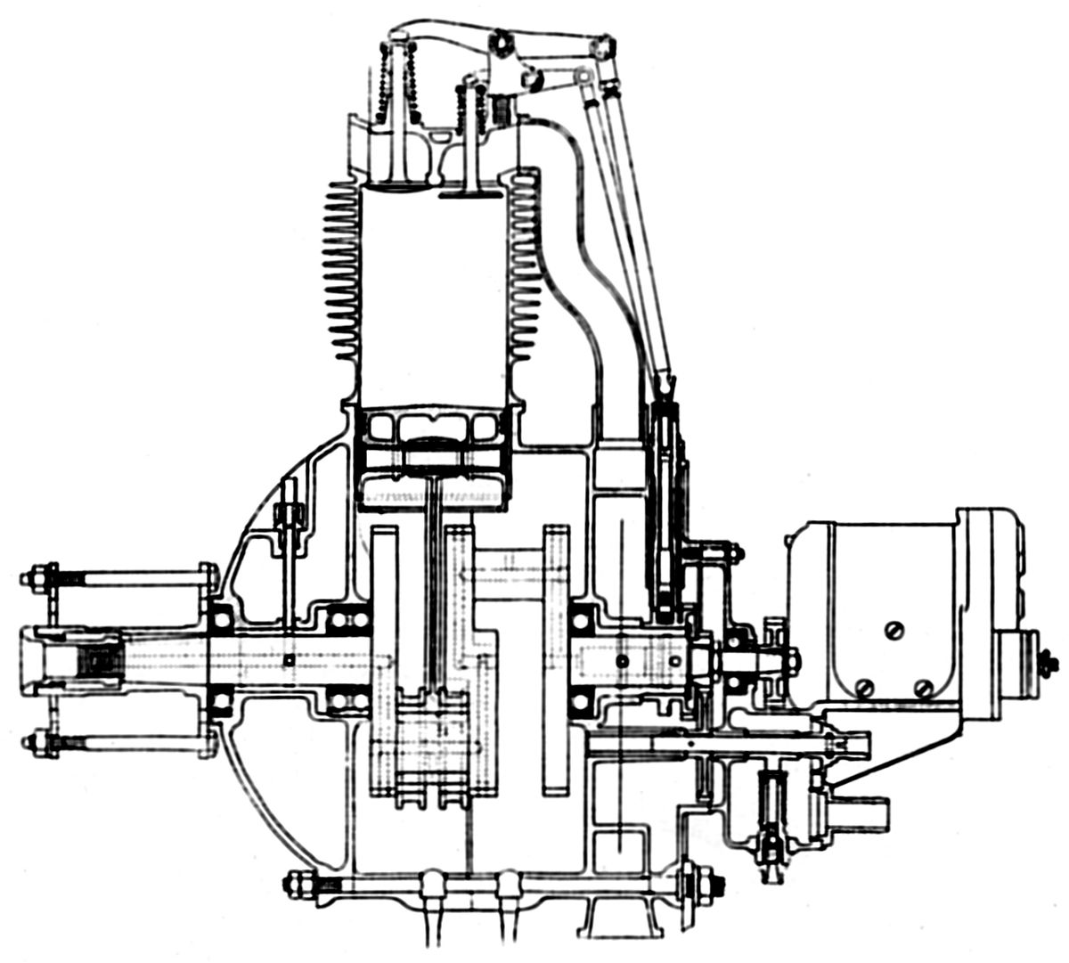
A two-cylinder horizontally-opposed air-cooled engine with a 90 mm (3.543") bore and 110 mm (4.331") stroke displaced 1.4 l (85.4 in³), weighed 75 lb and produced 24 hp at 1,800 rpm. The two cylinders shared the same axis as one used a connecting rod with a central crank throw while the other used two rods on two adjacent crank throws. The connecting rods used roller bearings and the crankshaft ball hearings for the crankshaft.
| Power hp @ rpm |
Cylinders | Bore mm (") |
Stroke mm (") |
Displacement l (in³) |
Weight lb |
|---|---|---|---|---|---|
| 45 @ 1800 | 3 | 105 (4.134) | 120 (4.724) | 3.117 (190.2) 150 | ? |
| 60 @ 1,700 | 6 | 90 (3.543) | 120 (4.724) | 4.58 (218.5) | 175 |
| 85 @ 1,800 | 6 | 105 (4.134) | 120 (4.724) | 6.234 (380.4) | 265 |
| 120 @ 1,600 | 10 | 105 (4.134) | 140 (5.512) | 12.123 (739.8) | 340 |
| 225 @ 1,600 | 10 | 125 (4.921) | 150 (5.906) | 18.408 (1,123.3) | 500 |
 |
 |
| 2-Cylinder, 24 hp (A39) | 6-Cylinder, 70 hp (A39) |
In 1929 the Anzani plant was sold to Henri Potez and production of Anzani engines ceased.
Argus
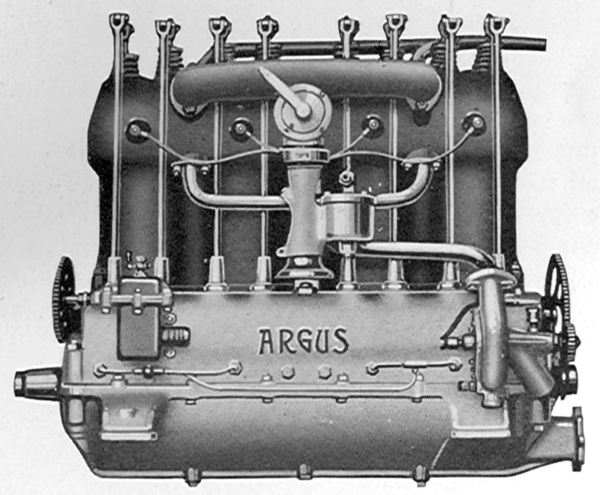
Argus Motoren G.m.b.H: of Berlin was established in 1902 to manufacture automobile, lorry and boat engines as well as automobile parts. Argus produced its first aircraft engine in 1906, the first in Germany. Starting in 1909, Argus began an extensive aircraft engine research and development campaign that positioned the company to furnish engines used for most German flying. In 1911, the Argus Works devoted its production exclusively to aircraft engines. Most early Argus engines followed automobile engine construction and, like most early aircraft engines, were not noted for reliability or low specific weight. However, Argus engines were so refined by 1912 that practically all German airplanes were equipped with them. The early engines were water-cooled in-line types of four or six cylinders that were cast in pairs. Valves located in the cylinder heads were operated by pushrods and rockers actuated by a camshaft on one side of the crankcase. The pistons were made from grey-iron castings and fitted with three rings. The connecting rods had H section shanks , and ignition was furnished by Bosch magnetos.
Most German firms, including the Argus Works, preferred steel cylinders of autogenously welded construction. During WWI Argus was occupied full time supplying war office contracts, building the 120-hp As2 and the 180-hp As3 in large numbers. Argus issued manufacturing licenses to several German firms.
 |
 |
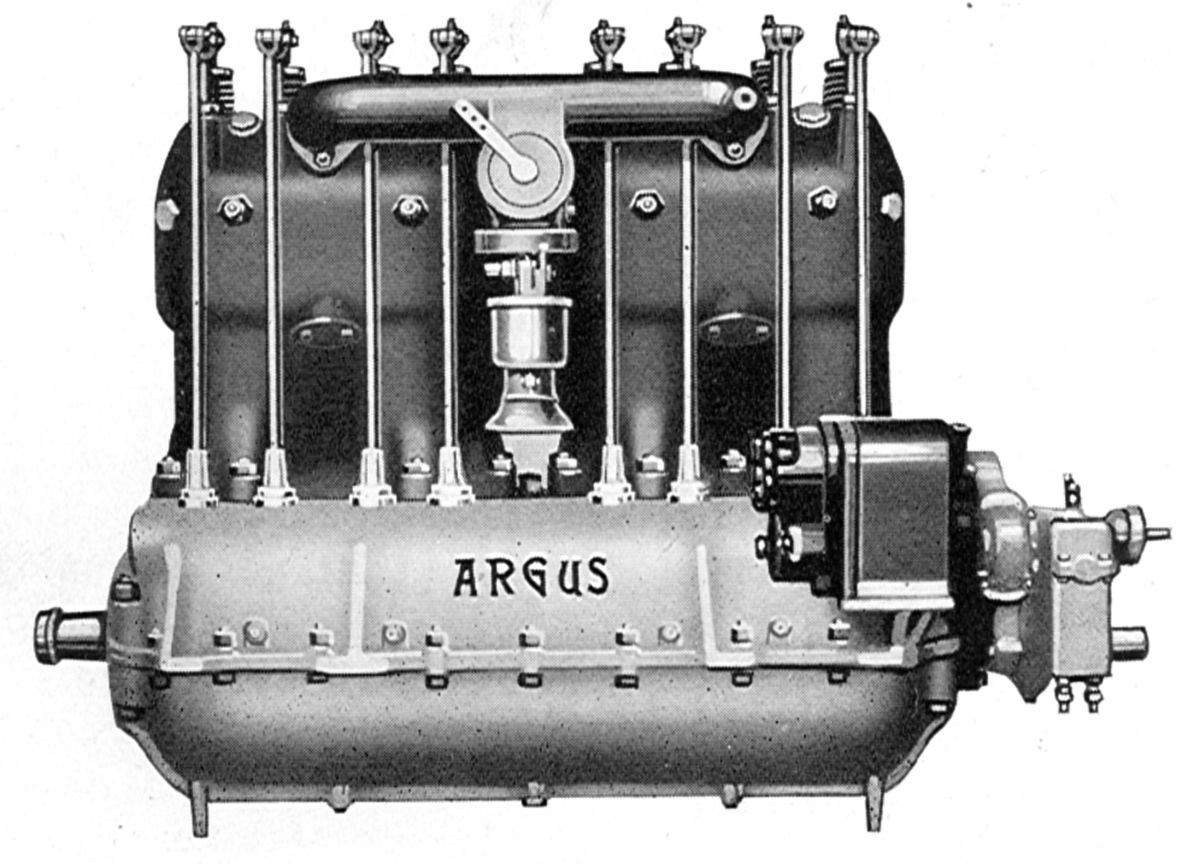 |
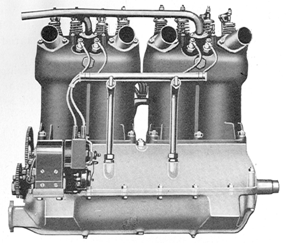
| Type I (AEE) | Type II (AEE) | Type IV (AEE) |
TYPE I was a four-cylinder engine with a 124 mm (4.882") bore, 130 mm (5.118") stroke, a 6.28 l (383.2 in³), and a 50 hp at 1250 rpm output from 264 lb, or 5.3 lb/hp. This engine was later rated 70 hp at 1250 rpm and weigh 287 lb, or 4.1 lb/hp, for a 115.7 psi bmep. Fuel consumption was 0.584 lb//hp/hr.
TYPE II was a four-cylinder engine with a 140 mm (5.512") bore and stroke displacing 8.621 l (526.1 in³). It was rated 100 hp at 1250 rpm, corresponding to 117.7 psi bmep. Splash lubrication was employed, fuel consumption was 0.527 lb/hp/hr, and weight was somewhere between 309 and 348 lb
TYPE III was an experimental six-cylinder engine with the same 124 x 130 mm cylinder as the Type I. Displacement was 9.419 l (574.8 in³) Rated 110 hp at 1,300 rpm, bmep was 116.5 psi, fuel consumption 0.578 lb/hp/hr, and the dry weight 430 lb, or 3.9 lb/hp.
TYPE IV was an experimental four-cylinder engine with a 155 mm (6.102") bore, 165 mm (6.496") stroke, and 12.454 l (760 in³) displacement that was rated 140 hp at 1,250 rpm and 150 hp at 1,300 rpm At 1,250 rpm the bmep was 116 psi. Dry weight was 420 lb, or 2.8 lb/hp at 1,300 rpm.
TYPE V was an experimental six-cylinder engine with the same 140 mm bore and stroke of the Type II, for a 12.931 l (789.1 in³) displacement that was rated 140 hp at 1,250 rpm, a 112 psi bmep. Dry weight was 529 lb, or 3.77 lb/hp.
TYPE VI was an experimental six-cylinder engine with the 155 x 165 mm Type IV cylinder dimensions, resulting in a 18.68 l (1,139.9 in³) displacement producing 210 hp at 1,250 rpm and 116.5 psi bmep. Dry weight was 683 lb, or 3.25 lb/hp.
 |
 |
 |
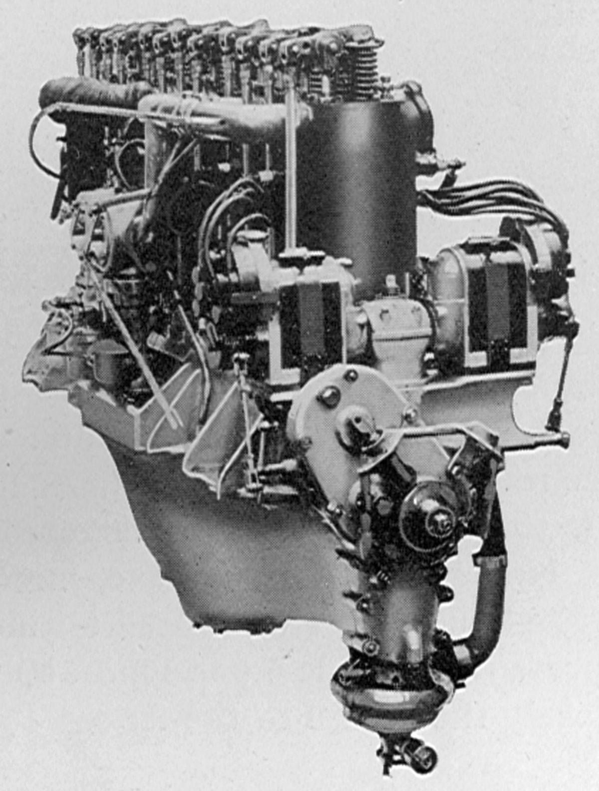
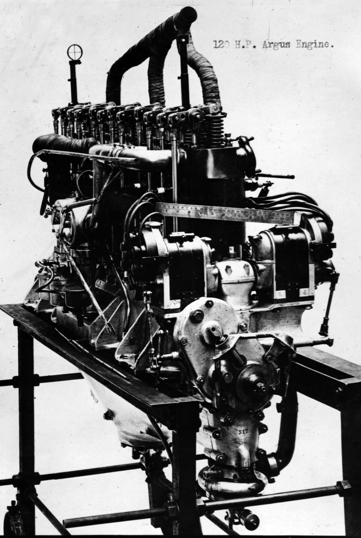
 |
| As 2 (AEE) | As 2 (NARA) | As 3 (AEE) | |
As 2 was a six-cylinder engine of 130 mm (5.118") bore,140 mm (5.512") stroke, giving a 11.15 l (680.4 in³) displacement and 120 hp at 1,350 rpm. A duplex Claudel carburetor supplied the mixture, a force-feed lubrication system was used, and dual ignition was furnished by two six-spark high-tension Bosch magnetos. The crankshaft was carried in four plain hearings. Light weight cast-iron pistons were ribbed on the interior and fitted with three rings.
As 3 was a six-cylinder engine of 145 mm (5.709") bore, 160 mm (6.299") stroke, having a 15.852 l (967.3 in³) rated 280 hp at 1,350 rpm. This engine was similar to the As 2 design.
As 4 was a water-cooled upright V-8 with a 130 mm (5.118") bore, a 140 mm (5.512") stroke and 14.866 l (907.2 in³) displacement. It produced 250 hp at 1,800 rpm and drove the propeller through a 3:2 reduction gear. Development began in 1918 with an experimental model known as the As 3a. It featured built-up steel cylinders with two inlet and two exhaust valves that were operated via rockers from single overhead camshafts. The carburetor situated in the Vee drew its air through cored passages surrounding the five plain crankshaft main bearings. Fuel was supplied to the carburetor by a pump, and a plunger pump provided pressure lubrication.
Manufacture of As 3 and As 4 engines ceased in 1919 as they were among the aviation-related items prohibited by the Treaty of Versailles. The entire material stock was destroyed and the manufacturing plant closed. Development of Argus aircraft engines resumed in 1923 with work on the As 5, a 24-cylinder double-W engine rated at 1,500 hp and intended for large commercial transport aircraft. Please see William Pearce's As 5 engine article. Argus began building superchargers in 1927 and in 1928 publicly exhibited the new As 6 and As 6a at the International Aeronautical Exhibition in Berlin.
 |
 |
| As 6 (A39) | As 6a (A39) |
As 6 was a water-cooled V-12 rated 700 hp at 1,500 rpm when normally aspirated and 1,000 hp at 1,700 rpm when supercharged. It had a 160 mm (6.299") bore, 180 mm (7.087") stroke, displaced 43.429 l (2,650.2 in³, had a 5.7:1 compression ratio and weighed 1,168 lb, and could be ordered for upright or inverted installation and with propeller reduction gearing. Each row of separate steel cylinder barrels shared a common aluminum head with four valves per cylinder. The fully-enclosed overhead camshaft was driven by an intermediate shaft and bevel gears. Part of the air entering the Sum carburetors on the turbo-blower installation was drawn through the crankcase to help cool the bearings.
The As 6a cylinder bore was increased to 165 mm (6.491"), which, with the same 180 mm (7.087") stroke, displaced 46.186 l (2,818.4 in ³).
 |
| As 7 (A39) |
In 1927 Argus began work on the As 7, an air-cooled nine-cylinder radial engine with a 600 hp normal rating that delivered an 800 hp maximum rating at 1,850 rpm. The bore was 160 mm (6.299"), stroke 200 mm (7.874"), displacement of 39.191 l (2,208.5 in³) outside diameter 57.09" and the weight was said to have been 1,114 lb. The As 7 engine was filled with Farman propeller reduction gears running at 1.6:1. Aluminum alloy cylinder heads with four valves were screwed and shrunk unto finned steel barrels.
 |
 |
| As 8 (A39) | As 8 Sections (A39) |
The As 8 was exhibited at the London Olympia Show in 1929. This four-cylinder air-cooled inverted in-line was rated 80 hp at 1,400 rpm and produced 110 hp at 2,100 rpm maximum. It had a 120 mm (4.724") bore, a 140 mm (5.512") stroke, 6.333 l (386.5 in³) displacement of 385, 5.3:1 compression ratio and weighted 247.5 lb, or 3.09 lb/hp. Fuel consumption was 0.484 – 0.506 lb/hp/hr and oil consumption was 0.022 – 0.026 lb/hp/hr. The engine was 42.126" long, 16.574" wide and 35.039" high. The crankshaft and H-shank connecting rods were chrome-nickel steel. Aluminum alloy pistons were fitted with two compression rings and one oil-scraper ring. Steel cylinder barrels turned from single forgings were bolted to cast aluminum heads with two vertical valves seating on bronze valve seats. Two Bosch or Scintilla magnetos on the front housing supplied two spark plugs per cylinder. Several more refined As 8 versions were produced, including the As 8-B rated 135 hp at 2,200 rpm and the As 8-R, a racing version that produced 140 – 155 hp. The As 8 series also formed the basis for the As 10, an inverted air-cooled 90° V-8 with the same 120 x 140 mm bore and stroke that displaced 12.667 l (773 in³) and was normally rated 200 hp at 1,800 rpm with a maximum 220 hp at 2,000 rpm rating. After its introduction in 1931, 28,700 As 10 engines were built before the end of WWII. These, as well as other models, were relatively low-powered engines used in training, utility and reconnaissance aircraft.
 |
 |
| As 10 (A39) | As 10 Section (A39) |
Argus introduced several other engine models, including the type 109-14, which powered V-1 flying bombs. These later engines, produced after 1930, are beyond the scope of this early engine treatment.
References
Angle, Glenn D, ed. Aerosphere 1939 (New York, New York: Aircraft Publications, 1940).
Anble, Glenn D, ed. Airplane Engine Encyclopedia (Dayton, Ohio: Otterbein Press, 1921).
FAA Type Certificate Data Sheet ATC 74
FAA Type Certificate Data Sheet ATC 119
Fey, Tom. Private Correspondence, 18 Feb 2022.
Gunston, Bill World Encyclopaedia of Aero Engines (Sparkford, Somerset: Patrick Stephens Limited, 1986).
Lumsden, Alec S.C. British Piston Aero-Engines and their Aircraft (Shrewsbyry, United Kingdom: Airlife, 1994).
Schlaifer, Robert. Development of Aircraft Engines (Boston, Massachusetts: Harvard University, 1950).
Image Sources: A39 = Aerosphere 1939; AEE = Airplane Engine Encyclopedia; Fey = Tom Fey; NARA - U.S. National Archives and Records Administration; NASM - National Air and Space Museum.
Send mail to
![]() with questions or comments about this web site.
with questions or comments about this web site.
![]()