Air-Cooled Cylinders 1
Air-Cooled Aircraft Engine Cylinders
An Evolutionary Odyssey
Part 1 - From the Past
by George Genevro
Should aircraft engines be liquid-cooled or air-cooled? This "difference of opinion" is about a hundred years old and without a doubt the argument will continue as long as piston engines power the airplanes we fly. The manner in which the question is stated is misleading, however, since all waste heat that comes through the structure of an engine is eventually delivered to the air. In "liquid-cooled" engines the coolant can be water, ethylene glycol, a mixture of the two, or one of the many other liquids that have been tried and found wanting. Its primary purpose is to carry heat from the cylinder barrel and head to the radiator through which air, the actual cooling medium, flows. Proponents of liquid-cooling–now as in the past–can point to some benefits and operational advantages such as lessened hazard of shock cooling an engine, being able to direct dedicated coolant flow to critical areas in the cylinder head such as the exhaust valve seat and guide area, flexibility in radiator placement, greater structural rigidity in the engine, and having the option of designing airframes with a relatively small cross-sectional area that could still house a powerful engine. With every advantage, imagined or real, there is almost always a price to pay. Those who opted for liquid-cooled engines had to accept added weight, greater possibility of battle damage in military applications, and greater system complexity as the penalties. Such is life.
The general concept of "liquid-cooling" an engine has remained basically the same since before the Wright brothers made their historic flight, except for some significant mechanical, chemical, and thermal improvements. Those who chose to cool engines by the seemingly simpler direct transfer of waste heat from the cylinder to the air have had a much more tortuous and rocky path to follow, generally speaking. The developers of effective air-cooled engine installations had to, among other things, invent effective engine cowlings, conduct extensive studies of the aerodynamic behavior of air inside a cowling and around cylinders, and deal with myriad metallurgical and other problems in the engine itself in order to extend the life of critical components. Many choices had to be made with regard to cylinder structure and arrangement, valve placement and actuation, the number of valves per cylinder, and the ratio of heat dissipation between the air and oil, to name but a few. As in most engineering activities where there is not an established body of information from which decision-making assistance can be drawn, wrong choices were made that doomed some promising engines and drastically extended the development process of others. Probing the "edge of the envelope" has never been for the faint of heart.
From the Past
Inline and V-type Engines
Conceptually, the air-cooled cylinder has always been associated with low weight and simplicity since no secondary means of heat transfer was necessary. Pioneer engine designers were well aware of this and one of the earliest successful air-cooled aviation engines was the V-8 that Glenn Curtiss used to power the June Bug in 1908. It reflected the technology of that era and the individual cylinders with integral heads were gray iron castings with relatively widely spaced fins. The choice of gray cast iron as a cylinder material was logical at that time. Its machining and wear characteristics were relatively well understood since it had been used extensively in manufacturing engines of all types. Curtiss no doubt understood that aluminum would provide much better heat transfer but it had been in commercial use for only about 25 years and suitable alloys for producing dense, strong, heat-treatable castings had not yet been developed. Also, an aluminum cylinder would have required a cast iron or steel sleeve, bronze or cast iron valve guides, and valve seat inserts, making the construction of the engine considerably more complex. While Curtiss no doubt also understood the value of deep, closely spaced fins on air-cooled cylinders regardless of the material used, foundry technology, particularly the making of baked sand molds and cores necessary for such castings, had apparently not progressed to the point that cylinders of acceptable quality could be cast consistently.
European thinking tended to follow the same trends with regard to materials and engine layout. Renault in France introduced an air-cooled V-8 with individual cast iron cylinders with integral heads in 1909. Attempts to increase the power output of this engine brought on drastic cooling problems that were only partly alleviated by use of an engine-driven cooling fan. Larger versions of the Renault engine in V-8 and V-12 form were developed and built in France and also by the Royal Aircraft Factory in Britain during World War I, but regardless of size the engines were characterized by very short exhaust valve life and extremely high fuel consumption. According to one author, (L.J.K. Setright) these engines traveled a fine line between thermal and mechanical disaster.
With the excellent vision provided by hindsight one can see that the Renault and similar engines were, to a considerable extent, fuel-cooled as a means of extending the life of certain critical components, particularly exhaust valves. This was a common characteristic of practically all of the air-cooled in-line and V-type engines of the World War I era. Specific fuel consumption on the order of one pound. per horsepower per hour at full power was not unusual. Incidentally, fuel cooling is not a phenomenon limited to the distant past. Aircraft of the World War II era powered by large radial engines generally left a trail of black smoke when the engine was running at take-off power, a certain indication that some of the fuel was not completely burned. This generally served to keep cylinder head temperatures within the prescribed limits and to cool exhaust valves and other hot spots in the combustion chamber thereby preventing detonation and/or pre-ignition.
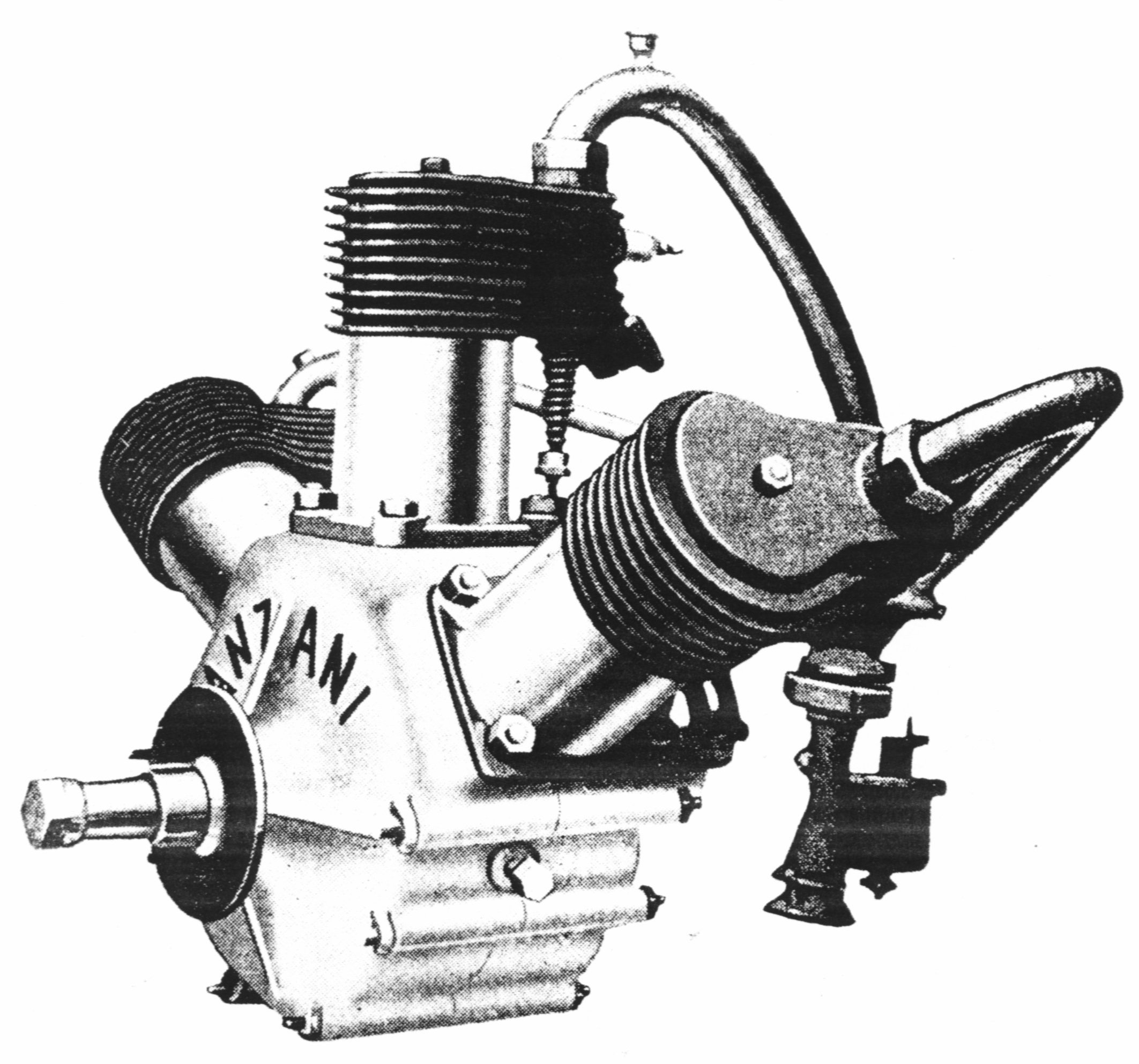
|
| The unusual 3 cylinder Anzani engine that Louis Bleriot used in his flight across the English channel had cast iron cylinders with "atmospheric" intake valves and cam-operated exhaust valves. Note the priming cup on the center intake tube. |
In 1909, a year that has been called "the year of practical powered flying" by some aviation historians, the air-cooled three cylinder "fan type" Anzani engine powered Bleriot's monoplane on its epic 37-minute flight across the English channel. This somewhat unusual engine had cast iron air-cooled cylinders with camshaft-operated exhaust valves and "atmospheric" intake valves that were kept closed by light springs and opened in reaction to the differential between atmospheric pressure and lowered pressure in the cylinder as the piston moved down on the intake stroke. It is surprising that this type of intake valve arrangement was used in early aircraft engines such as the Anzani when in practically all automotive engines of that era both the intake and exhaust valves were cam-operated. It did, however, eliminate one pushrod and rocker arm per cylinder, simplify the cam, and save weight.
Rotary Radial Engines
Direct air cooling was the natural choice for the designers of the rotary radial engines used extensively in World War I military aircraft. The machining capability necessary to produce the cylinders was readily available, and the major parts of the engine were machined from billets and forgings of alloy steel rather than from castings. The materials were very likely one of the low-to-medium carbon steels alloyed with nickel that were popular in that era. The first of the well-known French rotaries, the 50 horsepower Gnome, had been flown successfully in 1909. The power-to-weight ratio of the rotaries was generally better than that of other aircraft engines, a fact that made them attractive to aircraft designers. In response to military needs, larger rotary engines were manufactured in relatively large quantities in Germany as well as in France and Britain. Some rotary engines were manufactured in the U.S. under license agreements with the French. Near the end of World War I some twin-row fourteen and eighteen cylinder rotaries had been designed and tested but it is doubtful that any of these were used operationally.
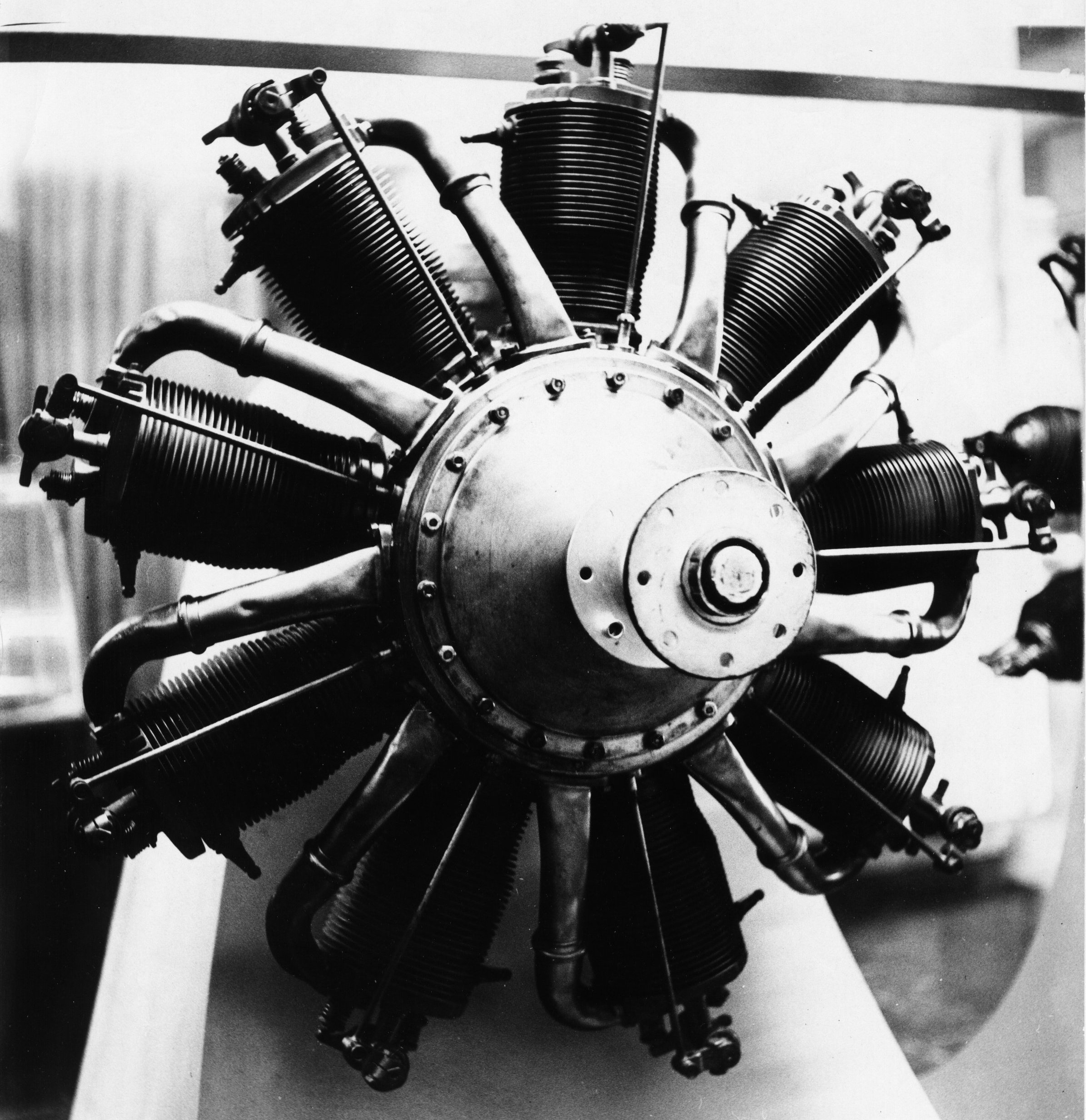 |
| The cylinders of the Le Rhone rotary engine of early World War I vintage were machined from steel billets and had relatively closely spaced fins. The single pushrod operated both the intake and exhaust valves by means of a semi-desmodromic cam ring. |
Since the typical rotary engine used in World War I fighters turned at about 1,200 RPM at full power and was enclosed in a partial cowling, the relatively shallow fins machined as an integral part of the cylinder were adequate for heat dissipation. The cylinder walls were quite thin and the head was usually an integral part of the cylinder, resulting in a clean, simple, and light structure. There were no exhaust manifolds on rotary engines and when the exhaust valve on top of the head was open the exhaust gases, which generally contained liberal amounts of castor oil, vented directly to the atmosphere inside the partial cowling used on tractor installations such as the Nieuport and Sopwith aircraft. Since there was no way to incorporate an oil sump or any sort of an oil recovery system into the structure of the engine, the lubrication system inevitably was of the "total loss" type.
While the rotary radial engine was quite satisfactory for certain specialized military uses, its idiosyncrasies–and there were many–made it unsuitable for commercial applications. By the end of World War I it was considered obsolete. One of its major drawbacks was that in operation it produced gyroscopic forces that were a challenge to many pilots–and a death warrant to some–when controls were actuated to change the aircraft's direction of flight. Another basic disadvantage of the rotary engine was that the windage losses were quite high because of air resistance to the motion of the cylinders as they rotated. After World War I, surplus rotaries were readily available but efforts to convert them to static radial engines were generally unsuccessful since cylinder head and exhaust valve cooling were very inadequate unless the cylinder was moving rapidly through the air. Today, the only operators of rotary engines are dedicated restorers of World War I aircraft and builders of replicas who strive for maximum authenticity.
Static Radial Engines
By the middle years of World War I a number of engine designers in England had come to the conclusion that the static radial engine layout offered the best path to developing militarily and commercially viable engines. There was also support for the development of air-cooled engines from the British Navy since Admiralty planners were convinced that such engines would be lighter for a given power output, easier to maintain, and less subject to battle damage, a matter of more than passing interest to pilots flying single-engined aircraft over water. Incidentally, U.S. Navy planners and aviators came to essentially the same conclusions in the very early 1920s. While there was some interest the 1930s and early 1940s in liquid-cooled engines such as the experimental Lycoming XH-2470 and Pratt & Whitney XH-3730, a 24 cylinder sleeve valve engine, it was of short duration. In the U.S. Navy, the air-cooled radial engine would reign supreme throughout World War Il and beyond in piston-engined aircraft
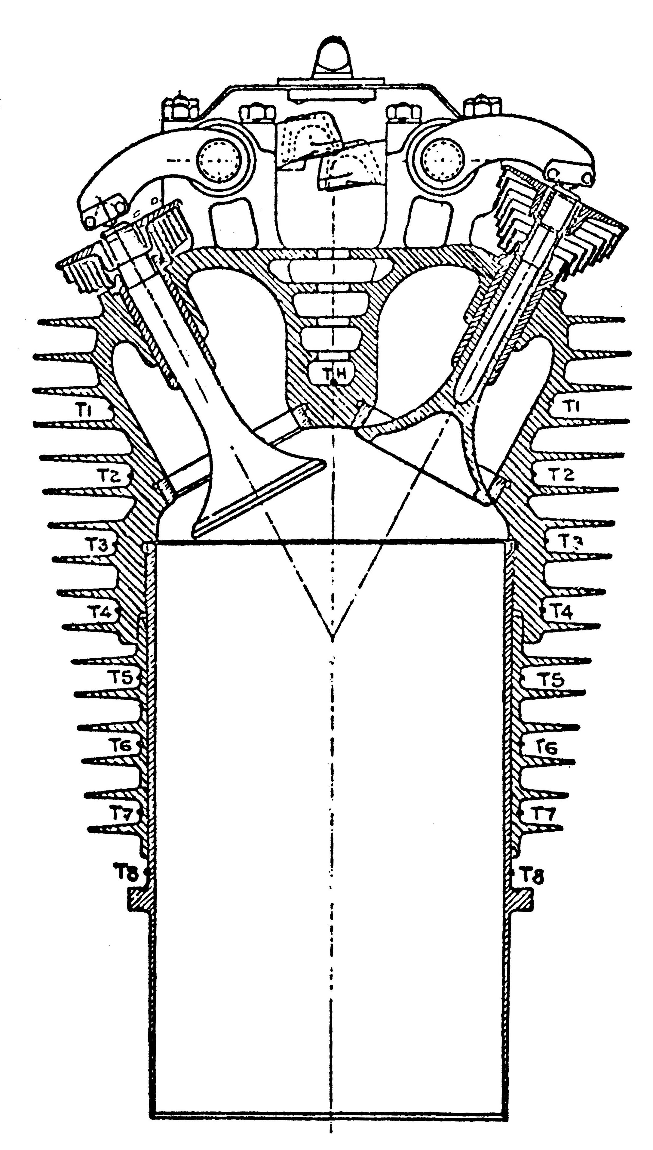 |
| The cylinder developed by Prof. A. H. Gibson and Sam Heron at the Royal Aircraft Establishment in 1918 had many modern features, including a mercury-cooled exhaust valve and an aluminum head with relatively deep fins. Note the unusual valve springs. |
During World War I British military planners and others who saw the need for engines that could be used in both military and commercial applications had come to the conclusion that cast iron cylinders were inadequate. The Royal Aircraft Factory (later called the Royal Aircraft Establishment), Britain's primary aviation research facility at the time, was directed to develop new cylinder designs. Professor A. H. Gibson and Sam Heron, two men who would have a profound effect on the evolution of the air-cooled aircraft engine cylinder, were hired. Both understood that aluminum transmitted heat well and decided that the head of the cylinder and some of the cylinder barrel fins should be aluminum castings and that the wear surface of the cylinder barrel should be a cast iron or steel sleeve. Bolted joints between the head and barrel were avoided because of the possibility of gasket failure and leaks in service, a matter that the manufacturers of the Kinner, Warner, and other small radials in the U.S. should not have ignored.
By 1918 Heron and Gibson had designed, manufactured, and tested cylinders that consisted of open-ended machined steel barrels with an external thread on a portion of the upper end and a mounting flange on the lower end. The finned cast aluminum head, which was fitted with valve seat inserts and valve guides, was internally threaded. The pitch diameter of the internal thread on the head was slightly smaller than that of the external thread on the cylinder barrel so that the head had to be heated in order to allow assembly. This resulted in a joint that was mechanically secure at the cylinder's operating temperature and provided the best escape path for waste heat. In concept, if not in exact detail, the modem air-cooled cylinder had arrived, but not everyone was ready to accept it, possibly because of the "not invented here" syndrome prevalent in some companies.
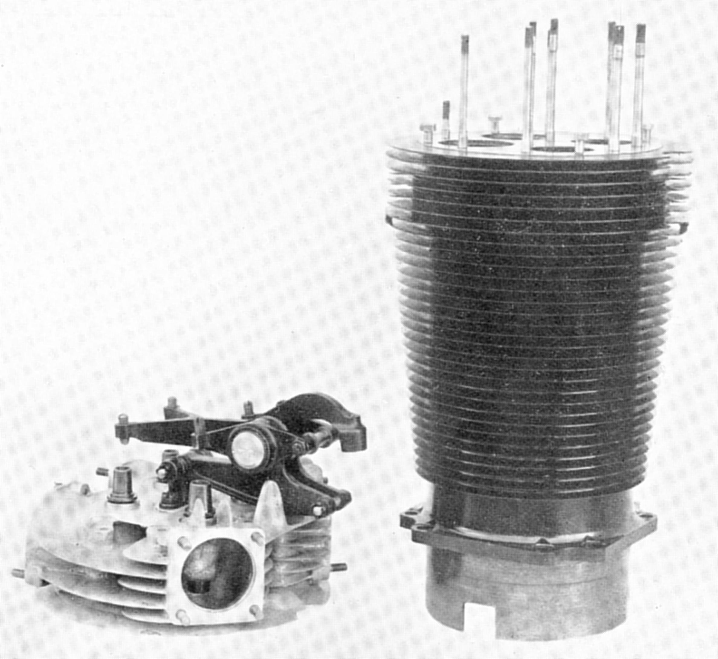 |
| The closed-end poultice type cylinder barrel of the Bristol Jupiter IV engine was made of steel and the head was held in place with cap screws and studs. |
Some British makers of air-cooled engines, apparently not realizing what the genius of Prof. Gibson and Mr. Heron had brought them, cast their lot with what was known as the "poultice" head design for air-cooled cylinders. The cylinder barrel was machined from a steel billet or forging with a flat, closed top end that had openings that served as valve seats. The early Bristol Jupiter (formerly the Cosmos) was a poultice head engine. On the early Jupiters, four valves with parallel stems were used, with the two exhaust valves at the front of the cylinder and the intakes at the rear. The choice of four relatively small valves rather than two large ones very likely stemmed from the belief that the smaller valves would run at lower temperatures and therefore last longer. The pushrods, rocker arms, and valve springs were exposed and parts such as the rocker arm pivot bearings required frequent greasing.
A cast aluminum head that incorporated the valve ports, valve guides, and rocker arm stands was attached to the top of the steel cylinder with bolts or studs. Since the fin area on the Jupiter head was quite limited, heat transfer from the combustion chamber to the air was poor and the head required frequent re-bedding to the cylinder. Engines using this arrangement were never completely satisfactory although they were widely used in a number or British and other European aircraft. The Jupiter was manufactured under license in a number of other nations. Since poor exhaust valve cooling and relatively short valve life had been a continuing and vexing problem, the acerbic Sam Heron once stated that Jupiter consumption should be stated in terms of pounds of exhaust valves rather than in pounds of fuel per horsepower/hour.
During the 1920s the Jupiter cylinder design was subjected to intensive development. Partly because of experiments with turbosuperchargers on the Jupiter IV and the introduction of geared internal superchargers in 1926, it became clearly evident that the poultice head was inadequate. Bristol finally gave up on the poultice head design and converted to a variant of the Gibson/Heron type cylinder at this time and retained the four valve per cylinder arrangement but with inclined valves in a pent-roof combustion chamber. It is interesting to note that the poppet valve Bristol radials were the only radial engines produced in any quantity that had four valves per cylinder. In an interesting mixture of old and new technology, the World War II era Bristol radials such as the Mercury had partially exposed rocker arms and valve springs mounted atop forged aluminum heads with machined fins and sodium-cooled exhaust valves and also had forged aluminum pistons.
Download this Article in .pdf Form
Send mail to
![]() with questions or comments about this web site.
with questions or comments about this web site.
![]()