Early Turbodyne
The Northrop Turbodyne (XT37)
by Kimble D. McCutcheon
Published 23 Oct 2023; Revised 2 Nov 2023
Early Turbodyne |
Aircraft gas turbine history tells us that two geniuses, Frank Whittle (working in Britain) and Hans von Ohain (working in Germany), independently invented and developed the aircraft gas turbine. The British were kind enough to share their gas turbine technology with the United States during WWII, and the resulting development formed the basis of the U.S. aircraft gas turbine industry. What is lesser known is that three indigenous U.S. gas turbine concepts were essentially contemporaries of Whittle and von Ohain. All of these gas turbine pioneers faced staggering obstacles. The Whittle and von Ohain stories are legendary, but stories of American gas turbine development are much less known. The early American gas turbines all sprang from the minds of visionaries who were far ahead of everyone around them. One example was the Northrop Aircraft, Inc. Turbodyne. |
Preface
Little has been written on the Northrop Aircraft Turbodyne. The author hopes that this article, which is based almost entirely on primary sources, will add something to what is known about the Turbodyne and its development. It is regrettably incomplete, but perhaps it will inspire others to do further research that will lead to a more complete treatment of this historic engine.
In May 2010, while working at the U.S. National Archives II in College Park, Maryland, I happened upon the U.S. Air Force Engineering Division Turbodyne correspondence file. More than thirteen years later, I set about the business of trying to make sense of it. The correspondence is very sparse and disorganized. It is primarily correspondence cover letters and contains practically none of the tantalizing reports, drawings, photographs and test data that the cover letters reference. Additionally, the correspondence file appears to have been a catch-all for a number of unrelated gas turbine projects. Accordingly, one must infer much from knowledge of the times' technical milieu, the patent literature, other work done by the key players, etc. Despite the obstacles, one can construct a spotty time line covering many key events, but there is still much missing. For this reason, the author has chosen a modified chronological presentation. This correspondence covers nearly 10 years over a period that saw many changes: WWII happened, people got promoted and changed jobs, job titles changed, the U.S. Army Air Corps became the U.S. Army Air Forces and finally the U.S. Air Force.
Like the Lockheed L-1000 story, this Turbodyne tale chronicles a genius ahead of his time and a company completely out of its depth trying to do something entirely novel.
Nomenclature
The terms MatCmd and AMC used here are short for all the polyonymous U.S. Army Air Service/Corp/Forces/USAF Materiel (Branch/Division/Command) Engineering Division titles used over time. To wit, Airplane Engineering Department, Aviation Section, Office of the Chief Signal Officer, U.S. Army, established October 13, 1917. Redesignated Airplane Engineering Division and transferred to Bureau of Aircraft Production, August 31, 1918. Redesignated Technical Division, January 1, 1919. Redesignated Engineering Division, Air Service, May 13, 1919. Redesignated Materiel Division, Air Corps, October 15, 1926. Redesignated Materiel Center (MC), Army Air Forces (AAF), March 6, 1942. Redesignated Air Force Materiel Command (AFMC), by General Order 16, MC, April 6, 1942. New organization, designated Engineering Division, established under AFMC by Notice 103, AFMC, June 7, 1942. AFMC redesignated successively Materiel Command, April 15, 1943; AAF Materiel Command, June 15, 1944; AAF Materiel and Services Command, summer 1944; AAF Technical Service Command, September 1, 1944; Air Technical Service Command, July 1, 1945; and Air Materiel Command (AMC), March 13, 1946. Engineering Division transferred from AMC to Air Research and Development Command (ARDC) by Notice 77, AMC, April 3, 1951. ARDC redesignated Air Force Systems Command (AFSC); and Engineering Division redesignated Aeronautical Systems Division of AFSC, effective April 1, 1961, by Letter AFOMO 590M, Department of the Air Force (DAF), March 20, 1961.
The terms MatCmd and AMC are also used when referring to a subordinate organization or person within Materiel Command speaking on behalf of Materiel Command or a subordinate organization when specific identification of the speaker is unimportant. The term BuAer is short for the U.S. Navy Bureau of Aeronautics. BuAer is also used when referring to a subordinate organization or person within the Bureau of Aeronautics speaking on behalf of the Bureau of Aeronautics when specific identification of the speaker is unimportant.
Introduction
In the 1930s, U.S. industrial gas turbines were lagging behind much of Europe. The Swiss firm Brown-Boveri et Cie developed the Velox boiler, a turbosupercharged forced-circulation water-tube boiler based on an axial-flow compressor and gas turbine. The Allis-Chalmers Manufacturing Company of Houston, Texas, licensed this technology for use in Houdry-process air compressors; the Houdry process efficiently produced high-octane gasoline using a fluidized catalyst bed and giant compressors driven by gas turbines to move petroleum fractions through the catalyst. Knowledge of these giant industrial turbines, which weighed about 13 lb/hp, soured U.S. Army Air Corps planners’ thinking about the viability of gas turbines for aircraft use. However, a few forward-thinkers saw possibilities.
Starting in 1925, Robert E. Lasley, a former Allis-Chalmers steam turbine engineer, secured several gas turbine patents for aircraft power (US 1,777,097, US 1,874,314, US 1,857,556, US 1,854,615). In 1930, he founded the Lasley Turbine Motor Company in Waukegan, Illinois, and by July 1934 had a running gas turbine. No U.S. military branch provided either encouragement or support, nor was there any commercial interest. In striving for efficiency that rivaled then-current reciprocating engine, Lasley’s engines were complex and had an industrial rather than an aircraft propulsion flavor. The Lasley Turbine Motor Company sank into obscurity during the depths of the Great Depression.[Schlaifer, 443]
The Turbodyne, a gas turbine developed by Northrop Aircraft, garnered more attention and support, and is the subject of this article.
A thrird gas turbine, the Lockheed L-1000 (XJ37), arrived only slightly later. This engine is the subject of a previous article.
Key Northrop Aircraft Personnel
 |
| Jack Northrop |
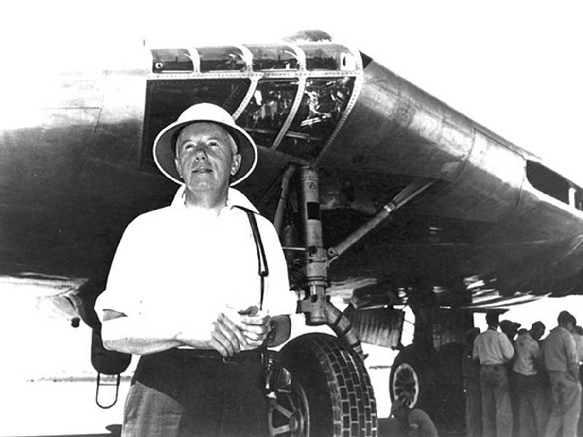
John Knudsen "Jack" Northrop (10 Nov 1895 – 18 February 1981) founded Northrop Aircraft, Inc. in March 1939. He had previously worked for Douglas Aircraft and Lockheed Aircraft. With several innovative but conventional aircraft designs to his credit, his real passion was flying wings, which he believed more efficient than their conventional counterparts. [Wiki]
Vladimir H. Pavlecka (20 May 1901 – 28 Jun 1980), born in Charvatce, Austria-Hungary (today the Czeck Republic), entered Prague Technical University in 1919, and in 1923 emigrated to the U.S.A. and completed his education at Union College, New York in 1925. He moved to Detroit, Michigan, where he worked for Buick and Aircraft Development Corporation, where he was chief of hull design for the ZMC-2, a metal-clad airship. In 1933, Pavlecka moved to Douglas Aircraft in Santa Monica, California, where he became head of the structural research department. There he help with DC-3 development, designed Douglas' first pressurized fuselage (the DC-4), and the first large-aircraft tricycle landing gear for the XB-19. While at Douglas, Pavlecka invented flush riveting and the elastic stop nut. He also became interested in the idea of gearing a gas turbine to a propeller (the turboprop) as a means of aircraft propulsion, made an analytical engineering study and calculated its performance. He was unable to get any anyone at Douglas interested in the idea. In 1939, Pavlecka's was able to interest Jack Northrop in his idea, and began work at Northrop Aircraft in November 1939.[Pavlecka]
Frederick Dallenbach designed the initial Turbodyne I annular combustion chamber. According to Pavlecka, Dallenbach contributed greatly to the Turbodyne, and got 93% efficiency from a small compressor driven by an electric motor. After leaving Northrop Aircraft in late 1942 or early 1943, he joined Garrett AiResearch, where he continued pioneering gas turbine work. He and Homer J. Wood won the Wright Brothers Medal in 1949 for a paper discussing auxiliary turbines to supply pneumatic power for aircraft based on the Garrett GTC43/44 and GTP70 units.[Wiki, Pavlecka Tape 3}
Arthur J. Phelan was Northrop Aircraft chief of research and played a critical leadership role at Northrop-Hendy and the Turbodyne Corporation during the 10 years the Turbodyne was in development.
Patents
| Application Date |
Award Date |
Patent Number |
Title | Inventor(s) |
|---|---|---|---|---|
| 19370223 | 19410304 | US 2,233,820 | Method of Riveting | Pavlecka |
| 19380423 | 19420224 | US 2,274,091 | Bucking Tool | Pavlecka Rechton Misfeldt |
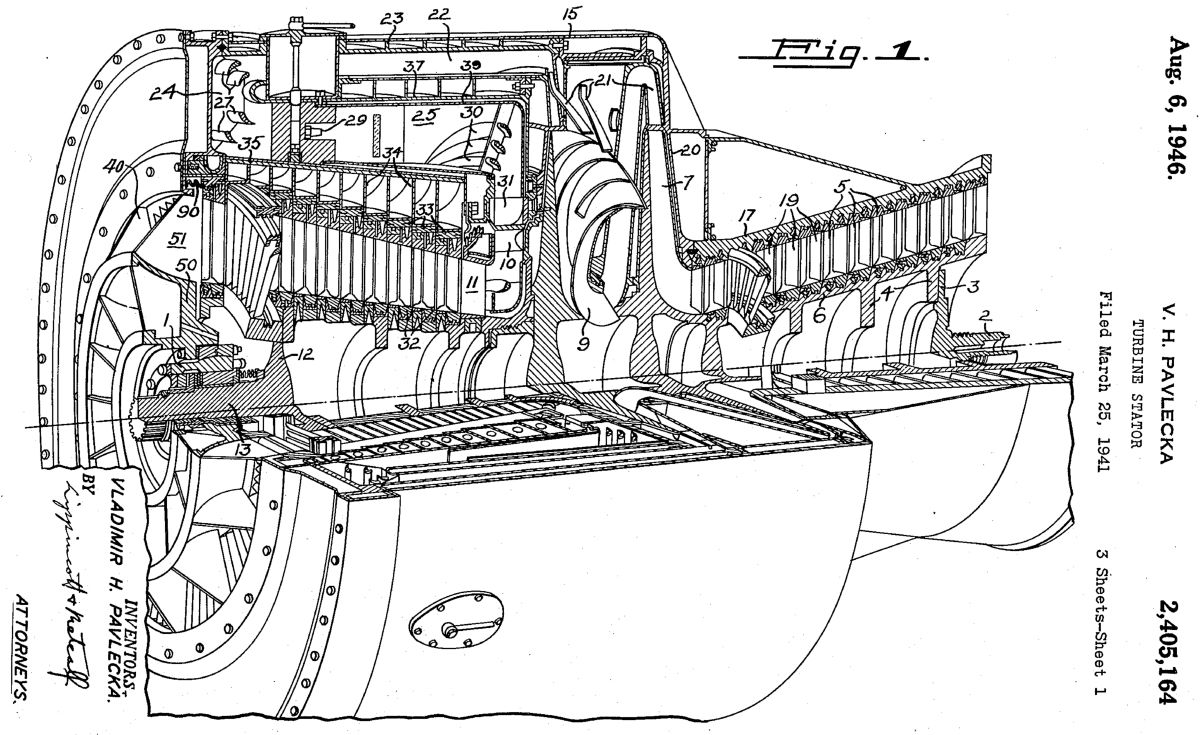
| 19410325 | 19460806 | US 2,405,164 | Turbine Stator | Pavlecka |
| 19411110 | 19461015 | US 2,409,446 | Airplane Power Plant | Pavlecka Northrop |
| 19410721 | 19470121 | US 2,141,551 | Compressor | Pavlecka Northrop |
| 19401011 | 19470304 | US 2,416,948 | Hydraulic Turbine Type Torque Converter and Fluid Coupling | Pavlecka |
| 19410303 | 19420915 | US 2,296,023 | Burner | Dallenbach Northrop |
| 19411119 | 19460618 | US 2,402,204 | Apparatus for Assembling Centrifugal Impellers | Phelan Pavlecka |
| 19420623 | 19461105 | US 2,410,588 | Turbine Blade and Assembly Thereof | Phelan Pavlecka |
| 19450406 | 19471104 | US 2,430,140 | Turbine Blade and Mounting | Phelan Walden McGaffey |
Chronology
Turbodyne I
November 1939. Pavlecka started work at Northrop Aircraft. In December 1939. Pavlecka attended a party at Jack Northrop's house where he discussed his jet propulsion ideas with the attendees; Theodore von Karman was there, and several other attendees were interested.[Pavlacka Tape 3]
2 Jan 1940. Using Northrop Aircraft funds, a small team, led by Pavlecka, began work on thermodynamic principles, cycles, and component preliminary design. The goal was a power plant that was lighter than reciprocating engines, which would be more powerful, vibrate less and have comparable fuel consumption of about 0.55 lb/hp/hr. This required a very high 10.5:1 pressure ratio and 85% efficient compressor and turbine, a tall order for 1940. Northrop Aircraft named the new engine Turbodyne. The private investment up to this point was about $25,000, but Jack Northrop believed it was impossible to proceed at private risk. He estimated that over $1 million would be required to make the engine successful. At that time, Northrop Aircraft net worth was between $3 and $4 million. To invest such funds on an uncertain endeavor was folly. The Army and Navy at first showed little interest, but finally both became intrigued with the Turbodyne concept, and on 30 Jun 1941 supplied a joint Army-Navy contract for its development. [Schlaifer, 446 – 447]
In March 1940, Pavlecka and Jack Northrop visited BuAer in Washington, DC, equipped with a beautiful, almost full-sized, color, three-quarter perspective, Turbodyne cross-section drawing. Apparently, this version was a pure jet, not a turboprop. At BuAer, they met with a Mr. Friedner, a civilian engineer and jet propulsion proponent. However, the officers, CDR Rico Botta and CDR S.D. Spangler, were not impressed. In parting, CDR Botta said, "God damn you, Pavlecke, don't you know that the decks of our carriers are wooden and they'll burn? Put a gear case on it and bring it back, we'll look at it."
In November 1941, Pavlecka met with Maj Donald J. Keirn and the civilian Power Plant Laboratory (hereinafter PPL) evaluation board. Pavlecki had two thick briefcases of documents, and went to the blackboard and started talking; nobody believed anything. When someone wrote an equation on the blackboard from memory and Pavlecka questioned its correctness, the board was antagonized . No one in the PPL had yet heard of Frank Whittle's engine. In 1941, Gen Arnold and Maj Keirn visited England and saw a jet airplane fly; thus began U.S. involvement with the aircraft gas turbine.
Since new heat-resistant alloys had recently become available, and industrial gas turbines were becoming increasingly prevalent, BuAer had requested an informal proposal covering design, construction and testing of one such power plant, but did not include propeller reduction gearing or accessory drives.
Jack Northrop proposed to complete the Turbodyne for $162,000, an estimate based upon the fact that over 5,000 hours of active design work had already been completed, along with about 5% of the total work. Thus approximately 100,000 hours engineering work remained at an average $1.20 per hour, plus 25% overhead and 8% profit. Work remaining including analysis, assembly drawings and detail drawings. Turbodyne construction and testing was estimated to be $758,440, which included $10,000 for raw materials and 215,000 labor hours at $1.10 plus 100% overhead and 8% profit. The labor hours assumed 75 hours per pound of power plant weight plus a 40% factor to cover redesign, spoilage and testing. Construction would include the manufacture and test of several axial compressor stages, one centrifugal compressor stage, and several high-temperature turbine stages. Testing would include sea-level Turbodyne calibration, plus sufficient operation at takeoff and normal power levels to justify final acceptance tests. Northrop Aircraft would furnish five test report copies.
Jack Northrop recommended that Turbodyne construction be done in a dedicated new 9,000 ft² building on Northrop Aircraft property that would cost $22,500. Mostly standard machine equipment costing about $153,000 could be re-sold. The building and equipment could be retained by the Government or sold back to Northrop Aircraft.
Jack Northrop opined that while initial design and construction costs might seem high, they were justified by the tremendous economical and tactical Turbodyne advantages.
While careful analysis suggested the Turbodyne, less propeller and accessory gearing, should be capable of 2,000 normal shp, 3,680 takeoff shp and weigh about 2,500 lb, Northrop Aircraft guaranteed a 20% or better overall thermal efficiency, 1,500 normal shp for 100 hours, 2,500 takeoff shp for 5 minutes and a dry weight below 3,000 lb. Jack Northrop maintained that if only the guaranteed specifications were reached, the Turbodyne would still be an extremely valuable development.
Development Cost Summary
Design = $162,000
Construction and Testing = $758,440
Total Experimental Expenditure = $920,440
Building = $22,500
Machine Tools and Equipment = $152,000
Total Recoverable Investment = $180,500
Total Project Expenditure = $1,100,990
Preliminary Equipment List
1 ea Large Engine Lathe, 36" Swing = $12,000
2 ea Medium Engine Lathes, 20" Swing = $7,500
2 ea Van Norman Mills #36 = $12,000
1 ea American or Cincinnati Horizontal Shaper = $3,600
1 ea Brown & Sharp Vertical Shaper = $5,000
2 ea Large Drill Presses = $4,000
1 ea Radial Drill 9" x 4' = $4,000
1 ea Surface Grinder = $4,000
1 ea Large Horizontal Boring Mill = $15,000
1 ea Large External Grinder = $7,500
1 ea Large Internal Grinder = $7,500
1 ea Large Vertical Boring Mill = $15,000
1 ea Heat Treat Furnace = $7,000
1 ea Rockwell = $500
Accessories = $30,000
Test Equipment = $10,000
Inspection and Checking Equipment = $8,000
Total = $158,000
3 Oct 1940. In an Inter-Office Memorandum to the Power Plant Laboratory (PPL) Chief, Air Corps Experimental Engineering Section Chief Maj Franklin O. Carroll, conveyed a Northrop Aircraft Turbodyne design study consisting of report sections R-13 through R-17 and one each of the following drawings:
No. 52000
No. 502009 – Layout – Double Propeller Drive – Preliminary
No. 502010 – Layout – Turbo Plant – Preliminary
One special carrying case containing one color Turbodyne perspective
Maj Carroll suggested that the proposed project be reviewed and a report prepared, after which the data were to be returned to the BuAer.
11 Oct 1940. Jack Northrop wrote Air Corps Materiel Division (hereinafter MatCmd) Maj Howard Bogart, enclosing the 13 Aug 1940 BuAer letter. Jack Northrop stated that since such cost estimation was difficult, his company was willing to consider alternatives such as building the first Turbodyne for actual cost, or cost plus a small fixed fee, etc. Jack Northrop stated that his company was not in the position to contribute more to the project than it already had. In addition to discussing the Turbodyne project, Jack Northrop's letter revealed his views on then-current experimental reciprocating engine progress and briefly stated progress on a few Northrop Aircraft designs.
Northrop Aircraft estimated that the above work would constitute about 1/3 of the total project cost, with the balance applied toward construction of an actual engine. BuAer had repeatedly suggested that the compressor work be contracted, but Northrop Aircraft opposed this strategy as the components were highly interrelated. Vladimir Pavlecka planned a conference with PPL personnel on 21 Oct 1940 at which time he would answer technical questions.
15 Oct 1940. In a telegram to Northrop Aircraft, Maj Carroll advised that Pavlecka should plan to be at MatCmd on 21 October, after which up to two weeks might elapse before any decisions were reached. Maj Carroll recommended that Jack Northrop delay his trip until that time. Lt Col Edwin R. Page, PPL Chief, in a letter to Maj Carroll, revealed that the PPL had numerous questions for Pavlecka and expected it would take about a week after the visit before PPL could submit a report and recommendations.
18 Oct 1940. In an IOM to Maj Carroll, the board appointed to review the Northrop Aircraft Turbodyne, which consisted of Capt D.J. Keirn (chairman), and MatCmd civilians Opie Chenoweth, Ford L. Prescott, E.A. Wolfe and A.L. Berger, submitted comments and recommendations including a request from Pavlecka for additional supplementary data and information.
30 Oct 1940. Jack Northrop wrote Maj Carroll suggesting a meeting at MatCmd for one to two days starting Wednesday, 6 Nov 1930 where Northrop Aircraft representatives would submit written replies to the various PPL questions from the 21 Oct conference. Northrop Aircraft would also discuss the possibility of entering into negotiations for the design and construction of one Turbodyne
1 Nov 1940. Maj Carroll wrote Jack Northrop, following up on the 11 and 15 Oct letters, which crossed Jack Northrop's 30 Oct letter in the mail. Maj Carroll stated that the PPL was withholding its decision on the Turbodyne merits until the answers to questions given to Pavlecka were received and carefully studied. Maj Carroll thanked Jack Northrop for the presentations and assured him that the Turbodyne project would be given earnest and prompt consideration if the study disclosed the data were scientifically sound.
15 Nov 1940. In a letter to BuAer authored by Maj Carroll and forwarded to the MatCmd Chief for signature, Maj Carroll established that during a recent visit by CDR Rico Botta, BuAer Power Plant Design Section Head, there had been considerable discussion about the Turbodyne. Northrop Aircraft had submitted data and made Pavlecka available for questions. Enclosed with the letter were the PPL questions and Pavlecka's answers. After studying Pavlecka's answers, the PPL had formulated additional questions, which resulted in another letter to Northrop Aircraft, also enclosed. MatCmd wondered whether BuAer's study of the Turbodyne might have resulted in similar questions and if said questions had been answered to BuAer's satisfaction.
While the theory presented by Northrop Aircraft suggested that the compressor and turbine were capable of operating at peak efficiencies at varying altitudes, MatCmd worried that accomplishing this in practice might involve variable nozzle boxes or controllable compressors, and wondered if BuAer had come to similar conclusions. A similar problem had arisen with water injected into the combustion chamber. If the Turbodyne were built and performed as anticipated, did the BuAer consider it a satisfactory aircraft power plant if its operation was limited to essentially one altitude with specific fuel consumption rapidly rising as power and altitude were decreased as indicated in the following table compiled from Report No. R-18, page 14?
Jack Northrop had explained that the Turbodyne would be required to cruise under practically 100% power with takeoff obtained using water injection.
The enclosed Tables I and II, were compiled to exhibit Turbodyne output with turbine and compressor efficiencies discussed with MatCmd personnel and using data from Reports No. B-19, pp 18-19, and Report 12, pp 9-10. MatCmd personnel understood that projected power was proportional to thermal efficiency, which was considered in these tables. If these data were in error, MatCmd requested that correct data be submitted.
| Turbine Efficiency, % | Compressor Efficiency, % | Power, shp |
|---|---|---|
| at Sea Level, No Water Injection | ||
| 90 | 83 | 1,640 |
| 85 | 83 | 1,388 |
| 85 | 75 | 1,146 |
| 84.5 | 78 | 1,214 |
| 80 | 75 | 861 |
| at 12,000 ft | ||
| 90 | 83 | 1,881 |
| 85 | 83 | 1,593 |
| 85 | 75 | 1,315 |
| 84.5 | 78 | 1,393 |
| 80 | 75 | 994 |
| at 18,000 ft | ||
| 90 | 83 | 2,000 |
| 85 | 83 | 1,692 |
| 80 | 83 | 1,369 |
| 90 | 80 | 1,906 |
| 90 | 75 | 1,729 |
| 85 | 75 | 1,398 |
| 84.5 | 78 | 1,481 |
| 80 | 75 | 1,056 |
27 Nov 1940. Jack Northrop responded to MatCmd's 15 Nov letter. The numbered points below correspond to those in MatCmd letter.
Point 2. Technical Report No. R-9, issued by Northrop Aircraft on 5 Apr 1940, was in error when it stated that the Turbodyne should rotate 1.81 times faster at 18,000 ft than at sea level. It was incorrectly assumed that the ratio of intake pressures at sea level and at altitude varied with the square of rotational speed. The formula
(p0 / pa) * (Pa / P0) = (ω0 / ωa)2 was incorrect and the formula
((pe - pi)0 / (pe - pi)a) * (Pa / P0 = (ω0 / ωa)2 was correct, where:
p0 = atmospheric pressure at sea level
pa = atmospheric pressure at altitude
P0 = density at sea level
Pa = density at altitude
ω0 = speed at sea level
ωa = speed at altitude
pe = compressor exit pressure
pi = compressor inlet pressure
Δpe = (pe - pi)0 = pressure increase at sea level
Δpa = (pe - pi)a = pressure increase at altitude
In Northrop Aircraft Report No. R-14 dated 1 Aug 1940, all data, including variation of speed with altitude, pertained to the high-pressure cycle that was proposed at that time; that cycle was superseded by a lower pressure cycle in accord with the theoretical analysis of the Ericsson cycle for maximum external work, i.e., when the compressor exit temperature and turbine exit temperature were located on the same isothermal. This was the cycle selected for Turbodyne design and was discussed in the Northrop Aircraft Report No. R-12 Appendices. Northrop Aircraft Report No. R-18, A Study of Speed Variation with Altitude, issued 1 Nov 1940, describes this revised cycle and was believed to be correct and final for the selected cycle. The curve of speed versus altitude in page 11 was particularly instructive and useful. It is proposed to design the 2,000 shp Turbodyne for 6,900 rpm at sea level when developing 100% rated power at no overload; see Report No. R-20. Theh Northrop Aircraft information submitted to MatCmd as the Turbodyne was developed reflected the convergence of ideas as well as honest errors that characterized the initial periods of any new engineering development.
Point 3. Theoretical Turbodyne partial-power performance was calculated for two operating conditions – a) with the turbine torque, including that required to drive the compressor, held constant, and b) with the speed held constant. Both cases, being theoretical, may not be precisely reproducible in practice. These data were submitted in Northrop Aircraft Technical Report No. R-19, Efficiency of the Turbine Cycle at Partial Power, dated 30 Oct 1940. A new and more realistic analysis appeared in Northrop Aircraft Technical Report R-20, Turbodyne Performance based on Entrophy-Enthalpy Diagram, in which partial power performance was a function of fuel supply and shaft power varied in speed and torque until an equilibrium between Turbodyne power output and propeller power input was established at a new level. Report R-20 was submitted with this letter. Jack Northrop withheld a promised analysis of efficiency variation with speed at constant external torque because no analysis method had been developed that could be checked on the E-E diagram and Jack Northrop preferred not to submit data that might be in error.
Point 4. During water injection, the total pressure inside the combustion chamber did not increase because of water injection; the vaporizing water filled the combustion space with a pressure of its own, known as the partial steam pressure that acted in opposition to the incoming compressor airflow, which was always at full static pressure and not diminished by the steam partial pressure. When water injection was active, the compressor airflow was diminished by the greater flow resistance but still delivered ample air for combustion. Northrop Aircraft had assumed the combustion chamber pressure remained constant, but it was a characteristic of all turbo-compressors that with diminished volumetric delivery the delivery pressure increased, while the compressor's adiabatic efficiency remained essentially constant for small volumetric changes, such as those under consideration here. This is another way of saying that the flow changes water injection produced were insufficient to induce what we would today call compressor stall. Reference to Kearton-Eck, Die Turbogeblase und Kompressoren, Fig. 143, page 171, shows that even a 50% volumetric delivery decrease, the stage adiabatic decreases only 12.1%. The theory of how water injection in gas turbines increases their power holds that water vapor replaces some of the air, partially relieving the compressor of providing enough air for cooling after combustion, with the cooling effect principally obtained from the latent heat of vaporization. In the Turbodyne, that power that would have otherwise driven the compressor becomes available as useful shaft horsepower.
This process was twice analyzed by two different methods, once in Northrop Aircraft Report No. R-9 and again in Report No. R-12. Both analyses arrived as substantially identical conclusions, with turbine efficiency remaining constant and minimal rotational speed change while water injection progressed. The thermodynamic analysis in a Report No. R-12 Appendix, the Turbodyne external power at sea level amounted to 37.2% of the total turbine power and the compressor load was 62.8% of total turbine power. Using methods and data from Kearton-Eck, the Turbodyne should obtain at least 0.628 * 0.355 * (2,000 / 0.372) = 1,204 additional shp by diminishing the compressor volumetric delivery by 50% by using water injection. At the 50% rated volume delivery and assuming a constant fuel supply rate, the amount of excess air would be 2,658 times the volume required for combustion, which means the fuel flow could be doubled before the Turbodyne began to work with excess air coefficients that are common to diesel engine combustion (about 30%).
This simple analysis using published data demonstrates that claims made for increased Turbodyne power using water injection are not exaggerated. Similar power increases would also be possible by temporary combustion temperature increases, a scheme that would be more attractive for an aircraft power plant. An example of this method appeared in Report No. R-20, and further refinement was expected as more detailed analysis proceeded.
| % Power | Sea Level | 12,000 ft | 18,000 ft | 24,000 ft |
|---|---|---|---|---|
| 100 | 0.558 | 0.478 | 0.445 | 0.415 |
| 80 | 0.608 | 0.511 | 0.475 | 0.445 |
| 65 | 0.710 | 0.598 | 0.549 | 0.505 |
Point 5. Northrop Aircraft never proposed or intended to use the Szydlosky-Planiol centrifugal compressor in the Turbodyne. The reference was cited to indicate progress in modern compressor design; similar results were cited for small compressors in NACA Technical Memo Nos. 839 and 949. The Szydlosky-Planiol exhibit two independent improvements. First, variable-pitch axial blading that controls the velocity and direction of incoming air, a feature desirable for superchargers working with relatively constant-speed airplane engines at various altitudes. This decreases inlet duct losses that would be caused by other throttling means at altitudes below critical altitudes. Similar results are accomplished in the U.S.A. by two-speed superchargers. The Turbodyne, a variable-speed machine, did not require variable inlet guide vanes as the airflow was gradually accelerated by properly-shaped compressor involute impeller vanes. Second, the principal adiabatic efficiency in the Szydlosky-Planiol was due to a diffuser with improved aerodynamic efficiency; similar techniques were practiced by other compressor manufacturers, such as Brown, Boveri & Company, Frankfurther Maschinen Fabrik, General Electric, etc. Proper diffuser design had a much greater effect on compressor adiabatic efficiency than the intake. Northrop Aircraft had extensive and up-to-date theoretical and practical information on compressor design, and saw no need to involve other firms unless some radically different and unusually successful scheme appeared in the future.
Point 6. Northrop Aircraft proposed to use a two-speed transmission with the Turbodyne because development of the hydraulic torque converter as shown on some layouts would delay progress if done simultaneously. However, Northrop Aircraft regarded the Turbodyne with the hydraulic torque converter to be the ultimate power plant design. Torque converter designs over 20 years old at the time were claiming 90% efficiency, but these were made of cast metal, did not employ modern hydrodynamic practice, and, hence, were not appropriate for aircraft use. Jack Northrop included a diagram reprint from Die Schiffmeschinen, which indicated that practically constant efficiency could be maintained through a wide speed range without resorting to variable-pitch; Northrop Aircraft expected even better efficiency with a variable pitch torque converter, such as those used on Kaplan hydraulic turbines and Escher-Wyss variable-pitch marine propellers. Regardless of its promise, Northrop Aircraft opined that work on the hydraulic transmission should be delayed until the Turbodyne was a completed and proven aircraft power plant.
Point 7. Tables I and II, compiled by MatCmd and submitted to Northrop Aircraft, were checked and were within slide rule accuracy. Northrop Aircraft attached three tables of recalculated power outputs at various turbine and compressor efficiencies for comparison with those supplied by MatCmd. The Northrop Aircraft tables presumed the Turbodyne developed 2,000 shp at 18,000 ft. Northrop Aircraft Report No. R-13 showed that the turbine, as defined during the early development stages, could deliver 2,000 shp at sea level, which means that the Turbodyne could deliver (0.339 / 0.278) * 2,000 = 2,440 shp at 18,000 ft, instead of the 1,640 shp as shown in MatCmd Table I.
11 Jan 1941. In Memorandum Report EXP=M-57-506-4, Capt Keirn reported the findings of the Board appointed by the PPL Chief to analyze the Northrop Aircraft Turbodyne. The Board concluded the Turbodyne might be a useful prime mover if:
a) The compressor efficiency was high (see Table 1).
b) The turbine efficiency was high (see Table 1).
c) The working medium temperature was fairly high (≥ 1,400°F).
d) The combustion chamber and turbine could withstand the working temperature.
e) The weight could be maintained sufficiently low for aircraft.
f) Starting was possible without excessive power input and weight.
g) Satisfactory takeoff power could be obtained.
h) Fuel consumption was within aircraft values.
i) Satisfactory durability and operational flexibility were attained.
The Board concluded that the Turbodyne had been more extensively investigated than any other known gas turbine design. [Author's Note: The work of Frank Whittle was still secret.] However, Pavlecka had no compressor or turbine design experience and his work to date had been purely theoretical. The Board opined that proceeding with full engine development would be a serious mistake, and that the only way the Turbodyne's feasibility could be determined was to build certain components and check actual performance. [Author's Note: This attitude may have hamstrung the project. Numerous gas turbine and rocket engine developers have attempted component test rigs only to abandon them because the components operate as part of a highly interrelated system, not to mention that the test rigs, due to their complexity and extraordinary power requirements, become formidable engineering projects in their own rights. This point will become clear as the PPL Board's plan below is examined.] The PPL Board recommended that Turbodyne development proceed in phases.
Phase 1. Design and construct the proposed Turbodyne compressor except that it should be provided with an end plate with bearing supports and a gear box to permit testing by the Government (presumably this means USAAC and/or US Navy. The initial assembly should not include the axial-flow blades so that performance of the first two centrifugal stages could be determined. The compressor assembly would then be completed by the addition of the axial stages and its complete performance determined. The following information was to be supplied:
1) Compressor efficiency:
2) Delivery characteristics under the varying operating conditions required for aircraft use:
3) A weight consistent with aircraft practice:
Phase 2. Design and construct the proposed Turbodyne combustion chamber and turbine, which would be added to the compressor.:
Phase 3. Turbodyne performance and endurance testing for 50 hours at rated power.:
Phase 4. Design and test a starter, starter drive and accessory drives.:
Phase 5. Design and test the propeller reduction gear.
17 Jan 1941. Jack Northrop wrote BuAer's CDR Botta notifying him that Northrop Aircraft had found a machine shop that was suitable for building the Turbodyne compressor. This information was conveyed to Col Page on 21 Jan 1941.
28 Jan 1941. Jack Northrop submitted a proposal to CDR Botta to complete the Turbodyne design and construct a compressor that could ultimately be used in the complete power plant if its performance was acceptable. The engineering proposed was to include the work done to date, consisting of assembly drawings 502010, 502016, 502017 and 502018, and Report Nos. R-9 through R-21. The design would be completed and would include the compressor, turbine and accessories, along with detail drawings for all parts. Northrop Aircraft would analyze stress of all major parts, perform physical tests of all major structural materials at the working temperatures, and analyze stress concentrations and creep behavior. The blades, blade grids, gas ducts, etc. would be subjected to aerodynamic analysis. Northrop Aircraft planned to set up a small laboratory with the specialized equipment necessary for some of the tests.
Northrop Aircraft planned to construct one complete compressor suitable for later use in a complete engine designed to deliver 2,000 shp at 18,000 ft. The compressor was to include everything from the air inlet to the combustion chamber interface, would comprise approximately 12 axial and 2 centrifugal stages, and would include a lubricating oil pump. The same two main hydrodynamically lubricated bearings planned for the complete Turbodyne were to be used. An extension shaft would facilitate driving the compressor from an external power source. Ports for temperature and pressure measurement would be provided at various compression cycle stages. Northrop Aircraft proposed the compressor be tested in a laboratory chosen by the government and at government expense. Northrop Aircraft would provide a competent engineer to assist with the testing. Delivered volume and temperature rise would be measured and used to calculate the compressor's efficiency in accordance with American Society of Mechanical Engineers standard procedures. Northrop Aircraft guaranteed its compressor would be 75% efficient and would weigh less than 1,500 lb, including an end bearing, end casing and discharge scroll not required when the compressor was attached to the Turbodyne. Northrop Aircraft estimated the design engineering, drawings and compressor would cost $483,600 and would take 18 months to complete; progress payments were requested.
In the six months since the Turbodyne project was first presented to the government, additional study had confirmed every major advantage and disclosed nothing that was other than encouraging, indicating a high likelihood of successful project completion. Northrop Aircraft intended that all engineering and related laboratory testing would be done at Northrop Aircraft, that a subcontractor machine shop would build the parts, and that the final assembly would take place at Northrop Aircraft under design engineers' supervision.
6 Feb 1941. Lt Col Carroll wrote CDR Botta commenting on the Northrop Aircraft Turbodyne proposal of 28 Jan 1941. The PPL doubted that if the 75% guaranteed efficiency and 1,500 lb weight were achieved, the resulting Turbodyne would not be a satisfactory aircraft power plant and the funds expended for a complete design would be wasted. Lt Col Carroll was angling for a compressor-only design and corresponding price reduction. Lt Col Carroll noted that Northrop Aircraft had not mentioned supplying the requisite gearbox and wondered if the Navy might have a steam turbine or other power source for the compressor test rig. MatCmd strongly recommended obtaining options for the remaining project phases in order to better track cost and schedule. Memorandum Report EXP-M-57-506-4 had covered these points.
4 Mar 1941. Lt Col Carroll wrote Capt Keirn forwarding an article from a Swiss engineering magazine that Pavlecka had given to Col Howard Bogart during his recent visit to Northrop Aircraft. The article indicated that many engineers in other countries were extremely interested in aircraft gas turbines. The article's assumptions tracked very closely to Pavlecka's Turbodyne design. Lt Col Carroll suggested that if there was sufficient interest among PPL personnel that the Technical Data Branch translate the article.
29 Apr 1941. Apparently the Navy didn't think much of MatCmd's plea for staged Turbodyne design. BuAer informed MatCmd it was initiating a letter of intent to procure one Turbodyne, engineering data and complete drawings from Northrop Aircraft at a cost of $483,600. The Navy wanted to know if MatCmd would bear half the expense. MatCmd responded on 30 Apr 1941 saying that funds were not then available, but MatCmd intended to split the Turbodyne cost when 1942 funds became available. MatCmd further stated that the cost split was contingent on the USSAF, if it desired, getting at least half of the Turbodyne production. Lt Col Carroll began action to transfer the funds on 23 July 1941. BuAer informed MatCmd that Navy Contract No. 85598, Joint Army-Navy Turbodyne Project, had been awarded to Northrop Aircraft on 25 July 1941. At this point, correspondence regarding the Turbodyne contract ceases except for a single Cross Reference and Suspense Record dated 12 Sep 1942, which references a letter from BuAer to MatCmd dated 9 Sep 1942, "For your information and file is ltr Aer-E-446-GB C-85590, dtd 9-9-42 from BuAer together with Jack Northrop ltr, dtd 8-14-42, with RINA 1st Endorsement and one copy Northrop Aircraft Monthly Progress report for period ending August 31, 1942, with ltr of transmittal and RINA 1st End. Relative to Navy Contract 85598 – Joint Army-Navy Turbodyne Project." It would not be surprising that projects like the Turbodyne had gone to the far back burner after the U.S. entered WWII.
10 Nov 1941. Vladimir Pavlecka and Jack Northrop applied for a patent covering the Turbodyne, which was finally issued as US 2,409,446 on 15 Oct 1946. On 7 Aug 1943 the War Department Patent Liaison Branch had notified MatCmd that the patent had placed in secrecy. Apparently it remained so until after WWII ended.
End of 1942. Pavlecka left Northrop Aircraft. According to Pavlecka, a small, close-knit cabal of obsequious yes-men surrounded Jack Northrop and advised him on Northrop Aircraft affairs. It grew into a kind of subversive mafia that made working conditions intolerable. Dallenbach left shortly thereafter. [Pavlecka Tape 3] According to patent literature, both appear to have worked at the Turboelectric Corporation of Beverly Hills, California for a time.
10 Apr 1943. Capt L.M. Grant, the USN Inspector of Naval Aircraft (INA) working out of El Segundo, California, wrote the BuAer Chief informing him of a conference held at BuAer on 1 Apr 1943 during which Northrop Aircraft's requested that contract No. 85598 be cancelled because it no longer represented either BuAer's or Northrop Aircraft's idea of how to expedite Turbodyne development. Northrop Aircraft wanted a cost-plus-fixed-fee (CPFF) contract instead. If BuAer was unwilling to enter into a CPFF contract, then Northrop Aircraft wanted a $5,000,000 fixed-price contract or the elimination of performance guarantees so that Northrop Aircraft was not penalized by a long development program at its own expense to meet the guarantees. Northrop Aircraft opined that a complete and ready-to-run Turbodyne could be produced for the original price, plus options, totaling $1,233,600 and was willing to entertain a fixed-price contract for this amount provided Northrop Aircraft's responsibility to carry on forever in this little-explored field was mitigated. While Northrop Aircraft expected the Turbodyne to function satisfactorily at an early date, no one else had yet been successful in a field involving the high compression ratios and thermal efficiencies projected. Northrop Aircraft had been informed by others with considerable experience that compression ratios of 4:1 or 5:1 were difficult to achieve and that 10:1 compression ratios were extremely questionable. On the other hand, Northrop Aircraft saw no other way to achieve the high thermal efficiencies that were necessary for long-range operation and believed the current design should be vigorously developed. Northrop Aircraft's previous experience with the Navy, as well as other governmental and business entities, had established that the parties' true intent should be set forth in the contract and that verbal understandings and good will could not be relied upon. It was for this reason that Northrop Aircraft requested the contract change. If the contract change could not be made, then Northrop Aircraft requested that the contract be cancelled.
21 May 1943. BuAer produced a scope of work for the proposed new CPFF contract, along with several Engineering Production Planning and Detailed Scheduling enclosures
4 Jun 1943. CDR William H. Miller, BuAer Structures Section Head released Strength Requirements for Gas Turbine Power Plants for Navy Patrol Bomber Airplanes
8 Jun 1943. Col J.F. Phillips, MatCmd Developmental Engineering Branch Chief, wrote the MatCmd Aircraft Laboratory about BuAer's strength requirements for Navy patrol aircraft gas turbine engines. Calling the requirements "somewhat severe for a similar landplane installation", he forwarded the specification for review and comment, suggesting that the factors of safety should be reduced to avoid the weight penalty. Apparently BuAer was amenable to softening the specification.
21 Aug 1943. In mid-August, 1943, Northrop Aircraft requested that MatCmd supply a used Allison V-1710 similar to the -35 (an engine whose propeller reduction gearbox was remotely located, used in the Bell P-39) that would temporarily (about 90 days) be used to start the laboratory Turbodyne and power a full-scale compressor at various speeds for test work prior to turbine completion. This request should have been sent through the BuAer, so after paper was shuffled, MatCmd requested an engine from the Allison Engine Branch, Maintenance Division, Air Service Command. This engine would probably be a rebuilt model shipped from the Sacramento Air Depot directly to Northrop Aircraft. This story unfolded over several months.
25 Jan 1944. In a telegram from NOSIG Washington, DC to Commanding General AAF Materiel Command Wright Field, we learn several things:
1) The Turbodyne contract number and name has changed to NOa(s)1321 – Joint Army-Navy Northrop Aircraft Turbodyne Gas Turbine Project.
2) BuAer had advised MatCmd that an Allison V-1710-63 (used in the Bell P-39K/L) was being included in the Turbodyne test rig.
3) Northrop Aircraft had suggested a building a step-up gear, but BuAer suggested that the standard Allison 2:1 reduction gear, run backwards, should suffice and save about $9,000, and that if MatCmd was in agreement, that a reduction gear be provided.
4) The Joseph Hendy Iron Works of Sunnyvale, California could do the machine work to adapt the gear set. This is the first mention of Hendy, which was to play a more substantial role. However, correspondence and communication between Northrop Aircraft, Northrop-Hendy, Hendy and MatCmd were quite informal and for all practical purposes, interchangeable.
14 Mar 1944. Northrop Aircraft Report R-49, dated 6 Jan 1944, by Arthur J. Phelan, who appears to have taken over the Turbodyne work after Pavlecka's departure, details gas turbine work in Great Britain. Originally classified CONFIDENTIAL, the report was reclassified SECRET because it included engine performance figures.
21 Jul 1945. MatCmd cabled Hamilton Standard, Curtiss and Aeroproducts notifying these propeller manufacturers of a gas turbine under development. Two tachometer drives, AND10005, which rotated at 4,200 rpm at full engine speed were available. MatCmd requested comments by 25 Jul 1944 about whether this was suitable. Hamilton Standard strongly urged incorporation of governor drives in accordance with AND10010 and hydraulic provisions in accordance with AN9500 so that Hydromatic propellers could be used. Curtiss suggested that one AND10005 Type II governor drive running at 4,200 rpm was satisfactory and noted that a special propeller control system would probably be required; this could be either AND10005 or AND10010. No reply from Aeroproducts is in the correspondence file.
 |
 |
 |
 |
 |
 |
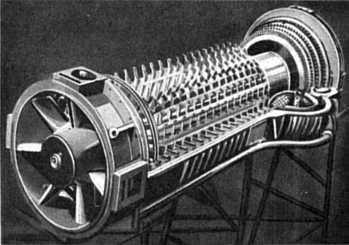 |
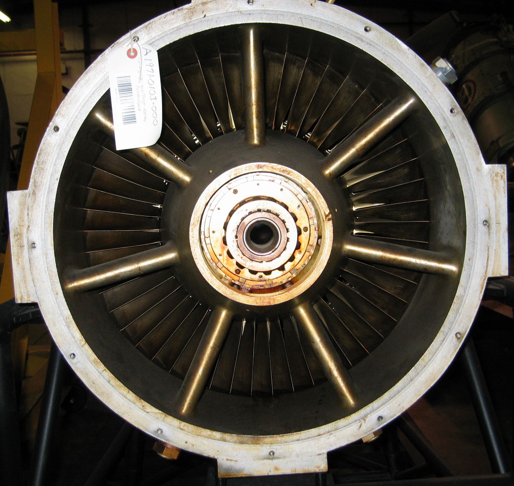
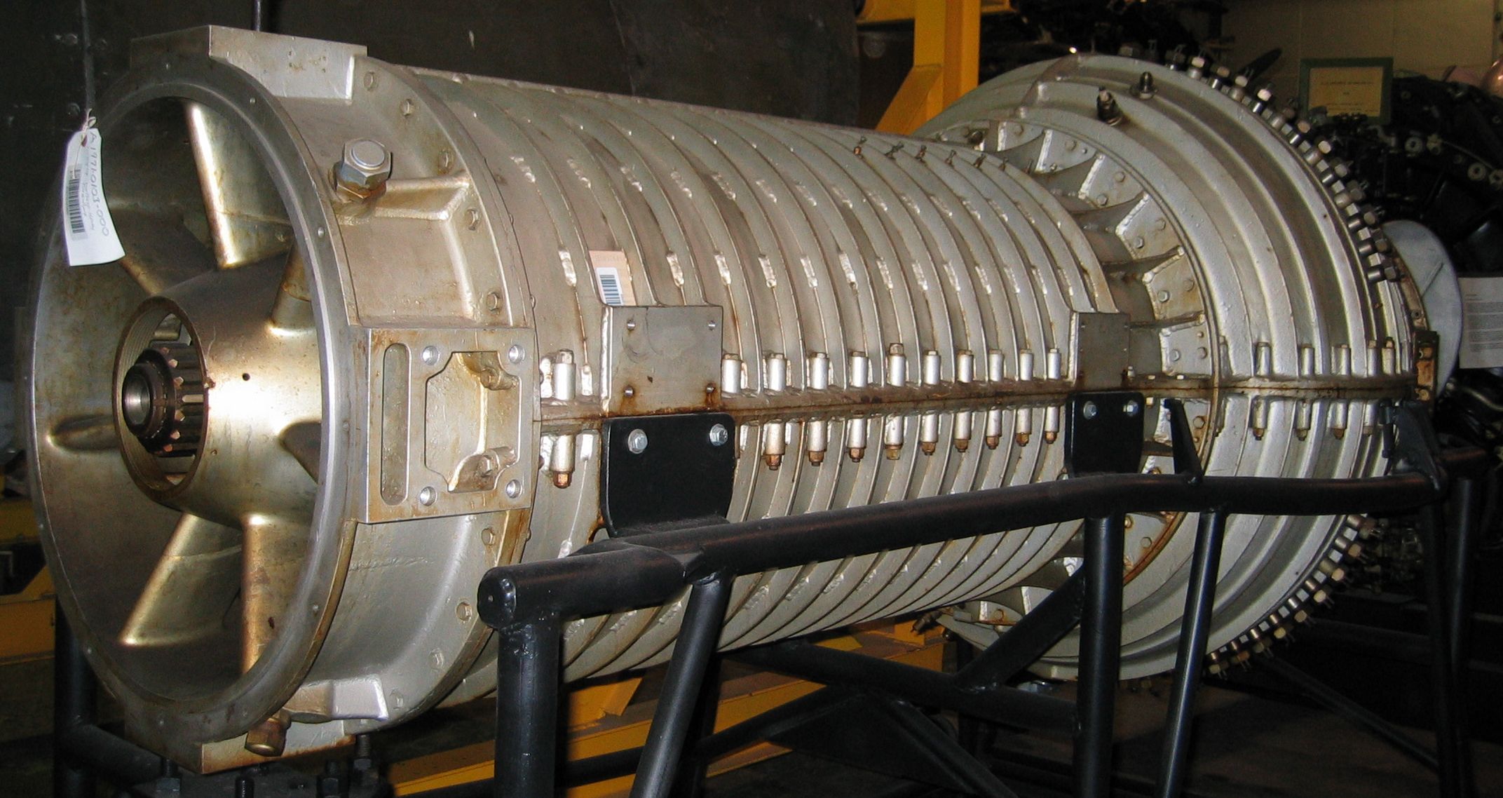
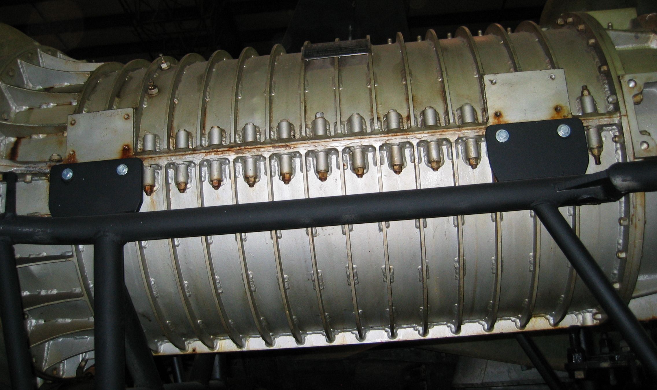
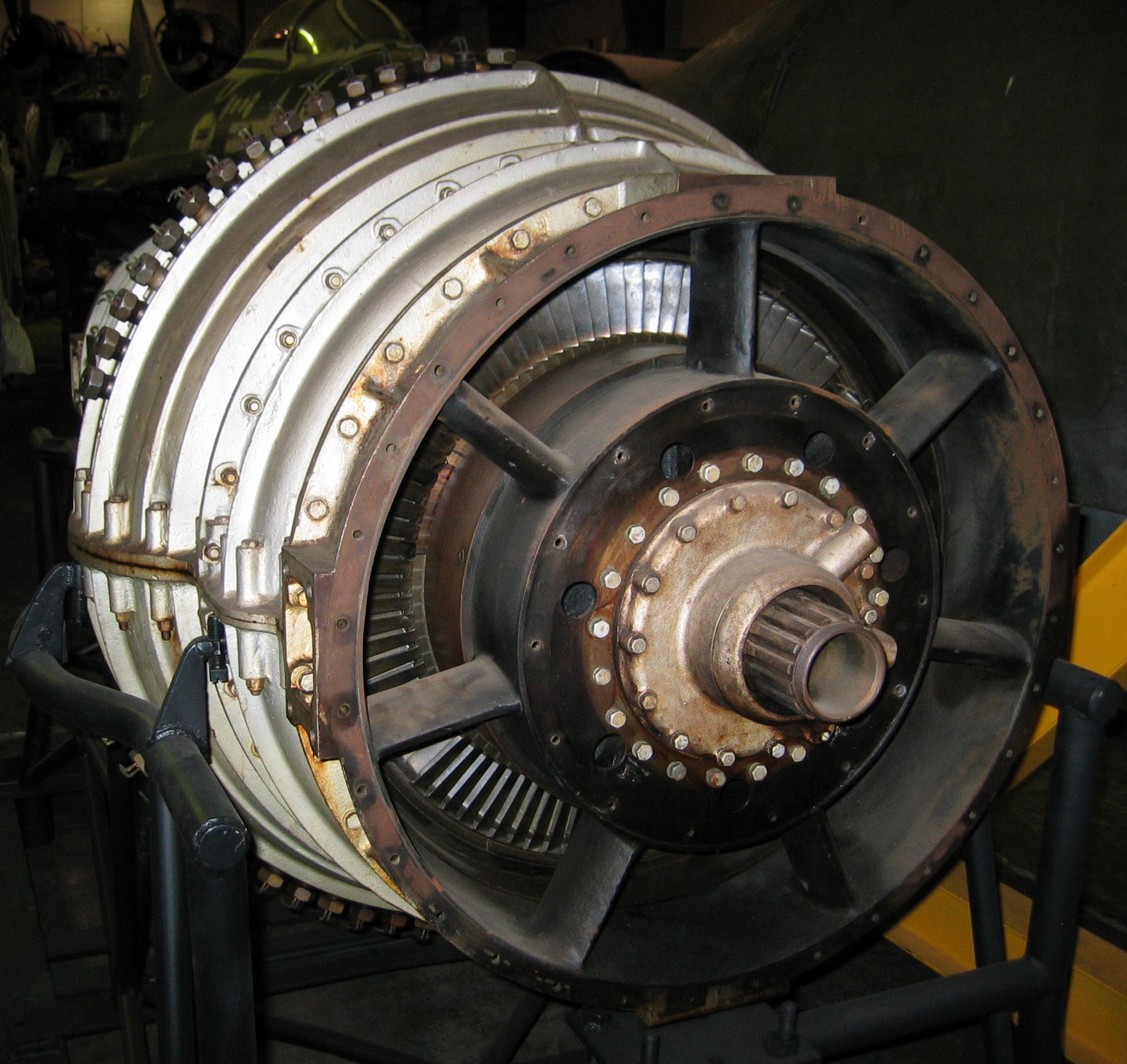
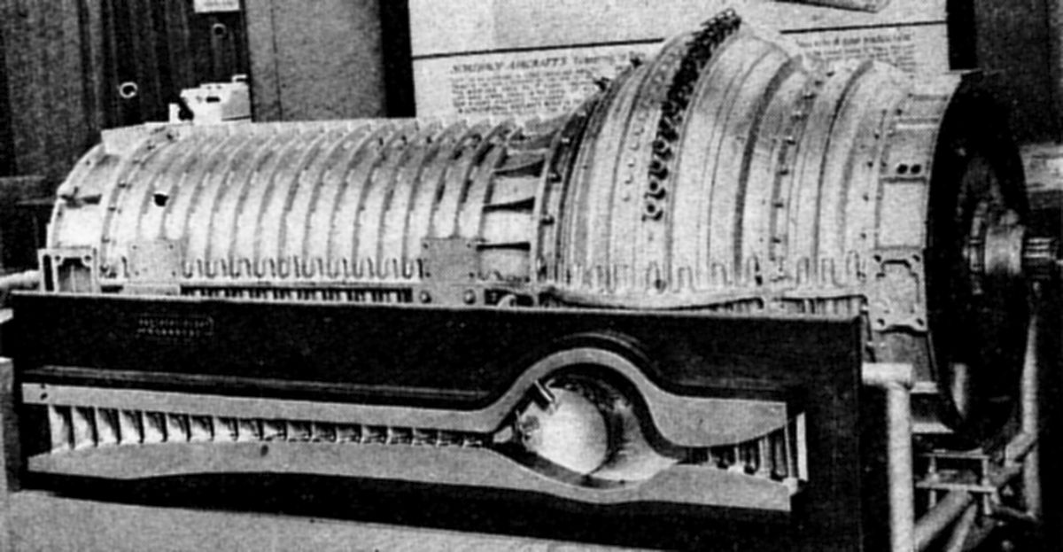
| Turbodyne I in storage at the NASM Paul E. Garber facility (author). Note the short annular combustion chamber. | From the 1946 National Aircraft Show, Cleveland, Ohio (2 Dec 1946 Aviation News). Interior, showing blading and flow path (Late 1947 Science et Vie). |
|||||
Turbodyne I Summary
We have seen the Turbodyne I evolve from the convoluted contraption depicted in early patents to something resembling a modern gas turbine. In the interest of simplicity, gone are the fluid coupling, axial/centrifugal compressor, and turbine with a seemingly endless blade cascade. Development has taken far longer and cost far more than anyone imagined. In the mean time, power requirements have increased astronomically, and the Turbodyne I has fallen behind the times.
Turbodyne II
The Turbodyne II was an Air Force contract that resulted in the XT37. Work on both the Turbodyne I and Turbodyne II proceeded concurrently.
18 Aug 1944. Col J.M. Gillespie, MatCmd Power Plant Laboratory Chief, sent copies of AAF Specification No XS-28602 – Engine, Aircraft; Internal Combustion Turbine (Propeller Thrust) General Specification, to practically every airframe and engine manufacturer in the U.S. Most were well known, but the Joshua Hendy Iron Works and the Frederic Flader Company also appear. Frederick Flader, Inc., based in Tonawanda, New York, was to receive an Air Force contract to develop the J55, a small unsuccessful turbojet that featured a supersonic compressor.
12 Sep 1944. In this letter we see the first use of the term Army Air Forces Air Technical Service Command (ATSC), Wright Field, Dayton, Ohio. Although this refers to the overriding "Engineering Division", the individual subordinate organization and laboratory names appear unchanged. Col R.C. Wilson, Development Engineering Branch Chief wrote Col Keirn, informing him of BuAer's 4 Sep 1944 decision to defer further action on the Northrop Aircraft Turbodyne expansion program. Engineering Division Chief Brig Gen F.O. Carroll replied for the Development Engineering Branch on 24 Sep 1944, noting that they were aware of the Northrop Aircraft/Navy interaction, and that the Air Technical Service Command proposed to negotiate a separate contract with Northrop Aircraft based n the AAF tentative specification No. XS-28602, for the complete development of such a gas turbine.
27 Sep 1944. Col Keirn notified the Engineering Division Chief that the PPL was initiating an Authority to Purchase covering the proposed Northrop Aircraft gas turbine, now known as the AAF Type T-B gas turbine (propeller drive). Since this development was secret, he requested that a secret project number be assigned. Subsequently, SECRET project number MX-562 was assigned to the Northrop Aircraft Turbodyne, and later amended as MX-562-A when General Electric tested and evaluated the engine.
9 Dec 1944. Col Keirn wrote BuAer requesting BuAer's permission to use certain test equipment and instruments purchased under the joint Army-Navy Turbodyne contract for a new AAF contract with Northrop Aircraft. Use of this equipment on the AAF project was not to interfere with the joint Army-Navy Turbodyne development work.
10 Jan 1945. This is the first report in an incomplete progress report sequence that appears in the correspondence file; at least one had been issued before. Maj Charles R. Hawks, Engineering Division Liaison Section Chief, issued a progress report on Navy Contract NOa(s)1321, Northrop Aircraft Turbodyne No. 1 (sub-contracted to Northrop-Hendy). Northrop-Hendy personnel Phelan, Ranney, Doubleday and Oliver reported that the first assembled unit had been moved into the test house and were being aligned. The reduction gearbox, drive shaft and propeller were installed. The propeller was a 14-foot diameter unit using a Hamilton Standard model 24F60 hub and 6497A-40 blades, serials 2478, 2479, 2480 and 2481. The Allison V-1710-63 engine, clutch and step-up gearbox were also installed and ready for operation. The Turbodyne propeller end had been located and the engine was being plumbed in. Shafts connecting the step-up gearbox and reduction gearbox were ready for installation. Test house instrumentation was complete, but the connecting lines were not yet connected to the engine. First run was expected in about a week.
According to Oliver, for the week ending 3 Jan 1945, shop personnel expended 1,165 man hours and engineering personnel expended about 1,374 hours. These were direct hours and did not include administrative, clerical and other overhead costs. While these numbers were believed accurate, Oliver cautioned they should not be used for cost accounting.
14 Feb 1945. On 12 Feb, Phelan, Ryder and Oliver of the Northrop-Hendy Company reported Turbodyne No. 1's monthly progress. According to Phelan, significant interference between the labyrinth seals and turbine rotor shrouds was noted when the engine was torn down following burning runs. The interference was worst on the 1st and 2nd turbine stage rotors, less so on the 3rd stage and only slight on the 4th. Phelan postulated several reasons for the interference:
1. The screws holding the labyrinth seals to the turbine housing had loosened, permitting the seals to contact the rotor.
2. The turbine housing may have not run as hot as predicted and thus did not expand as much as the clearance calculations had expected.
3. The turbine may have expanded more than predicted.
Several changes had been made to address the interference:
1. Additional screws attached the labyrinth seals to the turbine housing and these screws went completely through the seals rather than into the previous short, blind holes of the previous design
2. The seal rigidity had been reduced by undercutting their exteriors.
3. The new seals were installed in segments and then machined to produce a 0.015" clearance between the seal radii and turbine rotor shrouds.
Combustion chamber markings indicated some swirl was present, which caused carbon to accumulate on one side of the nozzle shields. The straightening vanes were apparently not sufficient to entirely straighten the airflow. A screen was added upstream from the nozzles rather than turning the nozzle shields to align with the flow. Some temperature stratification was present in the turbine blades as the roots were considerably hotter than the tips. An unperforated combustion chamber baffle section in line with the compressor outlets and fuel injection nozzles was introduced to prevent this stratification. An additional baffle was added inside the unperforated section to close the holes that permitted hot gasses to strike the blade roots. Turbodyne No. 1 had been reassembled and was being reinstalled in the test stand.
Drive clutch inspection showed considerable eccentricity in practically all rotating parts, which had resulted in structural weakness in the outer housing. A new back cover was machined with a groove containing the outer housing wall, which reinforced the outer housing. Clutch plate inspection revealed a 0.022" radial clearance, which may have resulted in considerable variation in the clutch balance and observed test stand vibration during operation. Outer housing retaining flanges, which restricted the clutch plate motion, had been built up to reduce radial clearance to a minimum. Because of centrifugal force on the clutch throw-out mechanism cast iron links, it was extremely difficult to de-clutch at high speeds. These links were replaced with Duralumin links; the clutch was to be reassembled on 12 February, balanced, and reinstalled by 15 February. The next runs were to be done at 6,000 – 6,500 rpm, with operation checks both with and without fuel burning. If no difficulties were encountered, an attempt to start the unit would be made. The bearings that supported the drive shaft after the Allison V-1710-63 was de-clutched were inspected and did not show undue wear. The clutch brake design was being detailed, but was not expected to be ready for the next runs. Since the support bearing condition was satisfactory, this brake was not absolutely necessary at this time. Phelan reported that Navy had approved the spares program and that spares were on order. Two complete turbine blade sets had been ordered from Haynes Stellite Company.
Turbodyne No. 2's rotor had been balanced and grooving for the turbine blades was being completed, to be followed by blade installation. Compressor grooving was completed and compressor stator blades were ready for installation in the compressor housing. The inner turbine housing was also ready for stator blade installation. Some machining remained on the outer turbine housing and some drilling of the bearing housing also remained. All bearings had been fabricated and combustion chamber work was also nearly completed. According to Joshua-Hendy personnel, if the 4th stage turbine blading was not received by 28 Feb 1945, the 15 Mar 1945 Turbodyne No. 2 delivery would slip.
Fourteen 4th-stage 4-6 chrome steel turbine blades received from Haynes Stellite were x-rayed before shipment, but Northrop-Hendy magnaflux inspection found cracks in eleven. Inspection of these blades confirmed previous results on DM-45 blades. While the cracks could not be located on the x-ray films, once they were identified by magnaflux they could be identified on the x-rays. Northrop-Hendy requested that Haynes Stellite cast some blades from N-155 material in hopes of getting some blading even if engine performance had to be restricted until satisfactory blading was obtained. These blades were to be fabricated with increased root radius and speed would probably be restricted to below 10,000 rpm. Haynes Stellite was unable to obtain the N-155 alloying elements for at least two weeks, making it doubtful that Northrop-Hendy would receive blades before 28 February. Thus, Turbodyne No. 2 would be delayed beyond 15 March. Joshua-Hendy personnel deemed it impossible to machine the blades from vitallium because the gap at the base was too small to permit using a tool with sufficient rigidity to machine the gap side contours. According to Phelan, the recently-formed Precision Casting Company of Pleasantville, New York believed it possible to fabricate these blades from DM-45 and was currently at work on same.
Oliver stated that Northrop-Hendy salaried personnel expended 1,970 engineering hours and 43 shop hours from 15 Jan through 31 Jan 1945. Hourly personnel expended 273 engineering hours and 879 shop hours during the week ending 24 Jan, and 314 engineering hours and 683 shop hours during the week ending 31 January.
17 Mar 1945. Col Keirn cabled Northrop Aircraft requesting a thermodynamic analysis of the MX-562 engine, if one existed, be forwarded to Capt J.E. Broadwell of the PPL.
24 Mar 1945. Memorandum Report TSEPL-5-506-50, "Development of the Turbodyne and the Design of a New Gas Turbine for the AAF", introduces a new contract number W-33-039-ac-6218, and details a conference held at Northrop-Hendy with ATSC personnel about Turbodyne development and testing progress and the design of a higher-power gas turbine. ATSC personnel witnessed a Turbodyne No. 1 test run, where previous difficulty with the Allison V-1710-63 drive shaft appeared to have been eliminated and the test ring functioned well. Runs with hot gas in the turbine were made at 5,000 and 6,000 rpm, with the Turbodyne almost self-sustaining during the 6,000 rpm run. No serious vibrational periods were encountered. Instrumentation recording compressor, combustion and turbine pressures and temperatures was very complete and functioned well. Combustion chamber temperature averaged about 1,300°F except for two 1,900°F spots just ahead of the nozzle diaphragm. Because of these high readings, it was decided to remove the combustion chamber and inspect the turbine nozzle diaphragm prior to additional test runs. The inspection did not reveal evidence of high temperatures, so the high indications were blamed on instrumentation errors and the thermocouples were moved inside the turbine nozzle blades to get direct temperature readings in the region of the suspect hot spots. Dr. W. Duncan Rannie, who had recently joined Northrop-Hendy, stated that the compressor airflow was low with the original Turbodyne compressor blading design, which had neglected the effects of centrifugal force due to the air's rotational component. This resulted in small blade angles at the blade tip than would have resulted if modified vortex theory blade angle design had been used. As a result, the airflow at design operating speed was lower than calculated. Rannie had studied at Cal Tech under Theodore von Kármán and helped explain why the Tacoma Narrows bridge had collapsed in 1940. Rannie temporarily worked for Northrop-Hendy during WWII, where he developed theories and design procedures for axial compressors; his work became the basis for the gas turbine technology that was to follow.[National Academy of Engineering]
Northrop-Hendy was working on an alternate combustion chamber with individual combustion chambers around the compressor outlets, like the General Electric I-16. This would result in a considerable increase in turbine diameter, but should be feasible for laboratory work if difficulties with the current annular combustion chamber persisted. The new combustion chamber scheme would be structurally weaker than the existing one; this would have to be addressed if it were incorporated. Phelan stated that Northrop-Hendy was negotiating with the Navy for additional Turbodyne units with modified compressor blading for a rotational development program. Phelan thought lessons learned in the Navy research would be applicable to the Air Forces compressor design. The tentative AAF turbine design layout was reviewed and the following aspects discussed with Northrop-Hendy personnel:
a) Bearing Arrangement. The improved turbine design incorporated a basic three-bearing configuration that allowed the turbine to be separated from the combustion chamber by variable-length extension shafts or directly connected. This scheme provided a more flexible turbine unit for either pusher or tractor installations.
b) Sea Level and Takeoff Power. It was decided that 7,000 net shp to the propeller should be used for design purposes. A pusher installation could use a smaller coupling between the turbine and compressor, but the turbine and compressor bearing support structure should still be good for 7,000 net shp.
c) Accessories. ATSC stated that the compressor, combustion chamber assembly and turbine should be laid out so that the accessories (lubrication pump, fuel pump, governor control systems, etc.) were incorporated within the engine structure as part of the turbine. Additional accessories and their placement were discussed, but no decisions were made as to their final arrangement.
d) Combustion Chamber Assembly. The axial space reserved for the combustion chamber assembly was 38", which appeared adequate for development of a satisfactory combustion chamber assembly. Since the rotor shaft was joined aft of the compressor case, whatever space was necessary for the combustion chambers could be accommodated. Northrop-Hendy expressed concern that the present contract called for only separate component design and testing; Northrop-Hendy did not have facilities to test compressor of this size unless they were hooked to the turbine. The ATSC took action to amend the contract so that it called for testing of an assembled unit.
ATSC personnel concluded that satisfactory Turbodyne test progress was being made and tentative test data indicated reasonably satisfactory operation. They recommended that the Northrop-Hendy improved turbine development program should be rated at 4,000 shp at 35,000 ft and accelerated to the greatest extent possible.
27 Mar 1945. Turbodyne No. 1 progress report as of 26 Mar 1945. The Turbodyne was ready to continue operational tests on 23 March, but the turbine bearing temperature was reading excessively high. This turned out to be a thermocouple problem, but since it was extremely difficult to replace without extensive teardown, the test engineers decided to ignore that reading and continue with the test program.
Vibration pickups had been installed on the reduction gear drive shaft to determine whether vibrations previously encountered on this shaft were noteworthy. These three pickups were set to measure deflections of 0.002", 0.005" and 0.010". A standard starting procedure had been developed whereby the Turbodyne was driven by the Allison and combustion started at about 3,000 rpm. After a five minute warm up period, the speed was increased to about 6,000 rpm and the Allison declutched.
Test No. 23 was completed on 24 March, during which it was planned to determine whether operation at higher speeds could be accomplished without vibrational difficulties. Speed was increased to 7,000 rpm, where it operated for about 30 seconds before being shut down. None of the vibration pickups indicated problems. The unit was then operated at 7,700 rpm for about 30 seconds, again with no noticeable vibration. It was decided to try even higher speeds. The speed was then held constant at 7,900 rpm for about 5 minutes, where the fuel flow was about 710 lb/hr. The speed was increased to 8,600 rpm for about 3 minutes, where the fuel flow was 730 lb/hr. According to Dr. Rannie, the maximum combustion chamber was 1,600°F with an average temperature of 1,300°F; average nozzle temperature was about 900°F. It was noted that the exhaust gas looked black and there was a strong kerosene odor, indicating a drop in combustion efficiency. Just prior to these runs, larger fuel nozzles had been installed and the nozzle chamber pressure was around 60 psi instead of the 200 psi that was used with the smaller nozzles at higher fuel flows. Test engineers attempted to manually adjust the propeller pitch to obtain speed control, but since fuel flow was also regulated, the degree of control due to the propeller was not determined. Data from this run were expected to be available on 26 March and results were to be given in the next report. Total time on Turbodyne No. 1 was 17 hr 55 min of which 5 hr 38 min were spent burning fuel.
Following this test the combustion chamber top and turbine housing top were removed for inspection. A significant carbon deposit increase on the fuel nozzle baffle left sides was noted, presumably from poor combustion efficiency. The swirl marks indicated a swirl reduction from the usual 30° to 15°. The downstream baffle had burn-through between the perforations in two places. The turbine section exhibited no appreciable changes and no interference was obvious. The unit was reassembled and additional runs at 9,500 rpm were to be made on 28 March. Test engineers planned to obtain performance data before going to higher speeds in case a destructive failure occurred.
A complete set of 4th stage turbine blades had been obtained for Turbodyne No. 2, but in order to complete the set, blades cast by both Hirsch and Haynes were used. All blades had been heat treated and were being ground. The complete set was to be turned around 27 March, and shipment to Joshua-Hendy was expected on 28 March. Bearing tests were under way and the bearings were expected to be returned to Joshua-Hendy on 29 March. The compressor was delayed because when the 13th stage blading was fixed with Cerrosafe, some shifting of the blading occurred. (Cerrosafe, a mixture of 42.5% bismuth, 37.7% lead, 11.3% tin, and 8.5% cadmium that melts between 158 and 190°F, is used to make reference castings.) After the blading had been machined, it was found that the spacers would not fit. New spacers were being made to account for this discrepancy. Northrop-Hendy expected Turbodyne No. 2 shipment on 1 May 1945.
Oliver stated that during the week ending 21 March, hourly personnel expended 134 engineering hours and 851 shop hours.
27 Mar 1945. A separate progress report, with an identical date, details that on 26 Mar 1945, Dr. Rannie, Messrs. Phelan, Douglas, Lim and Oliver of Northrop-Hendy reported Turbodyne No. 2 status. According to Mr. Lim, English design information indicated that the 4" diameter combustion chamber can obtain a maximum efficiency of 40%. A 6" diameter chamber efficiency increases to 80%; and an 8" diameter chamber has 90% efficiency. In general, these data were substantiated by Northrop-Hendy tests. Some test work was conducted on 4" chambers; however, most work has been done on 6" chambers. Both upstream and downstream injection had been tested up to 40 fps air inlet velocities. Various perforation arrangements were checked to eliminate the fuel center-core from the nozzle. It appeared that a 30° conical spray gave the best atomization. Up until then, most combustion chamber research was confined to fundamental design criteria and determination of basic dimensions to obtain satisfactory flame stability and propagation. It appeared that the axial combustion chamber will probably be from 36" to 48" in length; the first 12" was the diffusing area, the next 12" to 24" devoted to the nozzle area, and the remaining 12" used as a mixing chamber with no downstream baffle used.
Assembly of the model compressor with the first free-vortex blade set was completed and the first tests scheduled for 27 March. Tests were planned at various flow coefficients to determine efficiencies and pressure coefficients. Some blades were made using an NACA 4-digit contour, but owing to the hand finishing, no difference could be determined between the NACA and free-vortex blades. A second blade set was being designed to maintain a lower tip flow in order for the entire blade to operate at a constant Mach number. Dies for these blades were under construction, and it was planned to die-cast these blades. According to the latest information, the variable-frequency equipment that was to drive this test model was not expected before 1 May 1945. When this equipment became available, the model compressor was to be tested in conjunction with an external blower. Whirl tests on the large two-scale compressor indicated interference between the rotor and entrance blades and the high temperatures melted the strain gage attachment material. These gages were subsequently reinstalled and the compressor was nearly ready for additional tests. Full-scale compressor bearing requirements had been sent to Hayatt, Fafnir and M.R.C.; anti-friction bearings were to be used if at all possible. Tests on Turbodyne No. 1 indicated that 60 hp was required to overcome bearing friction at rated power. Three rotor disks had been machined and welded to develop assembly techniques and these disks were be subjected to whirl tests to determine strength with simulated blade weights.
The turbine design now envisioned using a single turbine disk on which all blades for the three stages were mounted. Turbine nozzles were to be air-cooled and full-floating in order to eliminate heat stress. Turbine stator thermal expansion was to be accommodated by radial locating pins that allowed radial movement. Because many personnel had been assigned to Turbodyne No. 1, not much additional work had been completed on this section and there was no appreciable design status change.
Mr. Oliver reported that during 1 Mar 1 through 15 Mar 1945 salaried personnel expended 2,067 engineering hours. Hourly personnel during the week ending 7 March expended 152 engineering hours and 719 shop hours. During the week ending 21 March, 157 engineering hours were expended and 561 shop hours were expended.
28 Mar 1945. Col D.J. Keirn opined regarding Northrop-Hendy Report No. R-55, An Investigation of Augmentors as Applied to Turbodyne I.
1. Concerning the straight augmentation scheme presented in Sketch A of the subject report, it is believed that the weight savings, 850 lb, over the original Turbodyne plus propeller, is nullified by the poorer overall cycle performance. However, since the cycle efficiency is much better than a simple turbojet, it is suggested that the possibility of further reducing the weight be studied with the idea of competing with the turbojet rather than the gas turbine cycle.
2. Before the propeller boost combination (Sketch B) can be completely evaluated, the drag of a non-operating booster (under cruise conditions) should be investigated. Further, it appears that a simpler tailpipe burning scheme together with an adjustable nozzle could be made to accomplish the same purpose.
24 Apr 1945. Turbodyne No. 1 progress report as of 23 Apr 1945 reported what appears to have substantial damage to Turbodyne 1 and to the test cell. Additional evidence indicating compressor blade failure may have been the cause for the accident that recently occurred on Turbodyne No. 1. Inspection of the blade bases revealed that the fore and aft were as thin as 0.025", whereas the specified dimension was 0.094". This wall thickness reduction occurred when the blades were set in the stages and the fore and aft faces were turned down so all faces were flush. Phelan stated that some blade bases were necked down at the web indicating tension failures. Calculations revealed that base wall failure would have occurred if the thickness was 0.035" when operated at the test conditions. It was assumed that the primary compressor blade base failure would have led to other parts failing in a logical fashion. Joshua-Hendy has requested Turbodyne No. 2 compressor section tear-down to inspect the blade bases, a process that could be accomplished without re-machining the fore and aft blade faces. This inspection is not expected to additionally delay Turbodyne No. 2 delivery because the 4th turbine stage delay. After polishing the complete 4th turbine stage blades, Joshua-Hendy found 22 blades defective because of hair-line cracks. No additional replacement blades were then on hand. Delivery of N-155 blades from Haynes Stellite as part of the spares program was expected in the near future. Because of this precision cast blade delay, Joshua-Handy fabricated one sheet metal turbine blade from 8-18 stainless steel, which was welded by the Heliarc process. This specimen was primarily for checking fabrication technique and was considered acceptable. Kirksite (a low-cost tooling alloy that could be accurately cast, requiring minimal finishing) dies had been made for additional sheet metal blades and Joshua-Handy was to fabricate several blades that were to be subjected to whirl and hot-tensile tests. If these blades were satisfactory, they were to probably be incorporated into Turbodyne No.2's fourth turbine stage. During this time, Joshua-Hendy also planned to install labyrinth seals on compressor stage seals No. 9 through 18. The turbine nozzle angle was also to be reduced. Except for the 4th stage turbine blades, the above work was not expected to delay unit completion beyond which the test cell was ready for test resumption. Much instrumentation had to be replaced as did a reduction gear pinion. It was estimated that five weeks would be required to fabricate a new pinion, and the main bull gear had to be removed and returned to the factory to determine if it was also damaged. Phelan estimated six to eight weeks would be required to get the test cell back into running condition.
Oliver stated that for the 1 Apr to 14 Apr 1945 period 1,077 salaried engineering hours and 53 salaried shop hours had been expended. Hourly personnel had expended 123 engineering hours and 560 shop hours for the week ending April 4; for the week ending April 11, hourly engineering personnel had expended 140 hours and hourly shop personnel had expended 733 hours.
1 May 1945. Col Keirn sent Northrop-Hendy the data requested on 24 Apr 1945, which predicted the need for a 15 ft diameter propeller. However, the ATSC was advised that an 18 ft dual-rotation and 25 ft single-rotation propeller was being considered for the Turbodyne II, which was a larger Turbodyne model whose design had just begun.
3 May 1945. Col Keirn advised Northrop-Hendy that the ATSC wanted design studies to be submitted so they arrived at ATSC no later than the last day of each month. ATSC further requested that a Northrop-Hendy representative be dispatched to arrive at the NTSC between the 7th and 10th of each month to discuss progress.
25 May 1945. Aircraft Section Chief Gen L.C. Craigie sent Experimental Engineering Section Chief Gen Franklin O. Carroll outlining the Turbodyne project to date
"1. Several years ago, when aircraft gas turbines were pretty much in their infancy, Mr. Jack Northrop brought in his preliminary design and presented the project to us for our consideration. After much discussion, we, in conjunction with the Navy, took on this development as a joint project. The development has now reached the point where the unit has run under its own power at approximately its design rpm. It failed, but the indications were that the failure could be attributed to faulty workmanship and not poor design. Certain features were definitely disappointing; the compressor and turbine were not well matched. Combustion is not accomplished as efficiently as desired. In spite of these known deficiencies, I believe the project is sufficiently promising to justify its continuation.
2. The development of any aircraft power plant is by its very nature expensive in terms of money and time. Because of the highly experimental nature of this project, we can expect it to be even more expensive than the development of a conventional reciprocating engine of comparable power. I believe the time has come when we should take a realistic reading on this project and answer to our own satisfaction the following questions:
a) Does the design possess sufficient merit to justify its continuation?
b) How much will it cost in time and money to complete the development?
c) Is the Northrop-Hendy Corporation (which to date has been 95% Northrop Aircraft, Inc.) qualified to complete the development?
d) is the design sufficiently promising and is the need for it sufficiently urgent to justify insistence on our part that it be removed from Northrop Aircraft and placed in the hands of a large and competent engine or machinery manufacturing organization?3) Mr. Jack Northrop is now completing plans to move his Northrop-Hendy Corporation into a Defense Plant Corporation facility formerly occupied by Joshua Hendy at Sunnyvale, California. He states that after this move Joshua Hendy will make available to Northrop-Hendy some of his best design and shop personnel. In the past, Joshua Hendy Iron Works' contribution to the project has been the performance on sub-contract some of the manufacturing for Northrop-Hendy."
On 7 Jun 1945, Col Keirn commented on behalf of the PPL, which agreed that a conference be held between ATSC and Northrop-Hendy to determine the extent they are prepared to expend equivalent engineering man hours and machine operating hours and provide similar company backed spares in the form of major forgings and castings to adequately carry out a development test program as other engine builders are doing. Col Keirn pointed out that Wright Aeronautical released 10 complete part sets to be processed through rough machine stages while they had an actual contract that covered a report on the design of a similarly rated unit, 4 completed turbine units and 200 hours of dynamometer test time. When Turbodyne development began there was no experimental data to help determine how certain components should be built. PPL believed that with certain design changes the Turbodyne would be successful. A need existed for such a unit in the 40-series bomber program. PPL did not believe that the program should be removed from Northrop-Hendy control if Northrop-Hendy was willing to expend the necessary effort to insure its success. Northrop-Hendy personnel are thoroughly familiar with the Turbodyne's characteristics and recent operating experience should help avoid pitfalls encountered in the past. PPL believed that complete AAF control of the Turbodyne II project would expedite its design and construction.
On 16 Jun 1945, Engineering Section Aircraft and Physical Requirements Chief Col Paul H. Kemmer provided his view: "Full credit should be given Mr. Jack Northrop for his pioneer engineering in this field of development. He proposed this basic design early in 1940 at which time little was known of any foreign developments of jet power plants, and our own power plant personnel were reluctant to give any support to the development of jet propulsion units. The only publicized developments were solid fuel rockets in Germany and Campani's approach, at that time. The Turbodyne involved none of those developments and was based upon independent American thinking. The Northrop Aircraft Turbodyne appears to incorporate most of the basic design features which will find their place in the jet propulsion units of the future. Full support of this original American design and its promoter is considered advisable." He thought the Hendy participation would be helpful and concurred with the suggestion that the project should be reviewed.</block quote>
18 Jun 1945. [7 Aug 1945 Conference with Northrop Aircraft and Joshua Hendy Iron Works Regarding Turbodyne Development, Memorandum Report TSEPL-5-538-5]. Gen Carroll explained the AAF's desire to expedite Turbodyne development. Jack Northrop said a previous difficulty had been the lack of machine shop facilities, which had been eliminated by partnering with the Hendy Iron Works to form the Northrop-Hendy, which had shop space and engineering personnel. At that time, Northrop Aircraft had 85 personnel working on the project, 50 engineers and 25 support personnel. Ultimately, they expected to employ 65 Hendy engineers for mechanical design. A 400' by 125' and 12,000 ft² floor space had been set aside exclusively for Turbodyne activities. The Turbodyne II project was Northrop-Hendy's first project and Northrop-Hendy was ready to proceed with same. J.L. Ray of Allis-Chalmers, who had six years gas turbine experience would be available to work on the Turbodyne as required. Northrop-Hendy's interest in gas turbines extended beyond aircraft propulsion to industrial and maritime applications. The Hendy Iron Works had been building steam turbines since 1940, having constructed about 100 8,500 – 9,000 hp turbines, 35 4,000 hp turbines, and 500 smaller units. Hendy Iron Works was developing its own line of industrial steam turbines, but its gas turbine work was confined to Turbodyne development. There was discussion of exchanging Northrop Aircraft and Hendy personnel for the remainder of the war in order to better staff upcoming gas turbine obligations. Northrop-Hendy had been hindered in hiring the engineering and supervisory personnel. BuAer wanted a two-stage test compressor built and delivered to the California Institute of Technology (CalTech), and a second engine to the Philadelphia engine laboratory either for running or for the Navy Yard museum. Gen Carroll discussed the Northrop Aircraft Turbodyne II proposal, which promised 26 units and requested the PPL study Northrop Aircraft's proposal, but believed that 10 engines would consume Northrop Aircraft's facilities during 1946 and recommended an option for the remaining 16 engines.[P340923]
17 Aug 1945. A letter from Northrop Aircraft to the ATSC, Northrop Aircraft Secretary T.H. Quayle reminded the ATSC that according to Memorandum Report TSEPL-5-538-1, certain items developed under the joint Army/Navy contract NOa(s)1321 were to be retained in connection with MX-562 development. Northrop Aircraft was specifically interested in the two-stage test compressor. Apparently, ATSC had decided that if the compressor remained at Cal Tech, that would satisfy Northrop Aircraft's requirements. This arrangement was extremely awkward, requiring continual transportation of equipment and instrumentation to and from Cal Tech, and further, to only do testing after midnight. Northrop Aircraft sought a plan to operate the compressor in the Northrop Aircraft Turbodyne I test cell in Hawthorne, vastly reducing the hours involved in transportation to and from Cal Tech.
Operating under the verbal agreement between Northrop Aircraft and the government that test equipment from Contract NOa(s)1321 could be used on MX-562 whenever applicable, the two-stage compressor had undergone modifications amounting to about $11,500 under AAF Contract W33-038 ac-6218; Northrop Aircraft took the position that 60% of the compressor belonged to the AAF contract, and that if the Navy persisted in its plan to make the compressor available for general research at Cal Tech, the AAF contract would be delayed.
Col Keirn wrote BuAer on 27 Aug 1945 requesting temporary transfer of the compressor from Cal Tech to Northrop Aircraft so that extensive Turbodyne II blade tests could be conducted. Data from the test runs would be available to BuAer and the compressor would be reinstalled at Cal Tech when the tests were complete. Col Keirn urged haste in BuAer's decision. Capt S.B. Spangler of the BuAer Power Plant Design Section replied on 12 Sep 1945, agreeing to make the compressor available to Northrop Aircraft. However, he advised the AAF reconsider running these tests at Cal Tech where the dynamometer, reduction gears and all associated test equipment was available and ready for use. He opined that setting up comparable facilities at Northrop Aircraft would involve considerable delay and would deprive Cal Tech of the opportunity to get an early start on a fundamental research program that would be in the interest of the entire U.S. gas turbine industry. That said, BuAer had no objection to the compressor and equipment transfer if the AAF so decided and asked that BuAer be informed of the scheduled move. BuAer agreed to the temporary move on 12 Sep 1945.
13 Sep 1945. Phelan cabled the ATSC outlining the two-stage test compressor's current configuration and the proposed test program. Experimental blades were fitted to the first two XT37-1 stages in order to explore compressibility effects, temperature rise and stage efficiency. Both rotor and stator blades were adjustable, and a complete test program verifying speed, pressure, blade angle and entrance vane angle would take nearly eight weeks for each blade configuration. This lengthy process was due, in part, the time required for tear-down and build-up for the various iterations of rotor, stator and guide vane angles. Another test series exploring other blades of varying design was scheduled to follow, and would explore Reynolds number effects on efficiency. Still another test series was to explore several pre-rotation vane designs. All of this would keep the compressor busy for 8 – 10 months. Note this is first time XT37 is mentioned in the correspondence file.
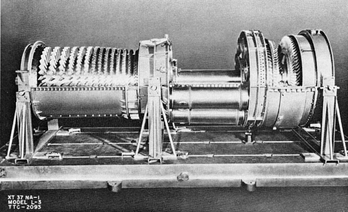 |
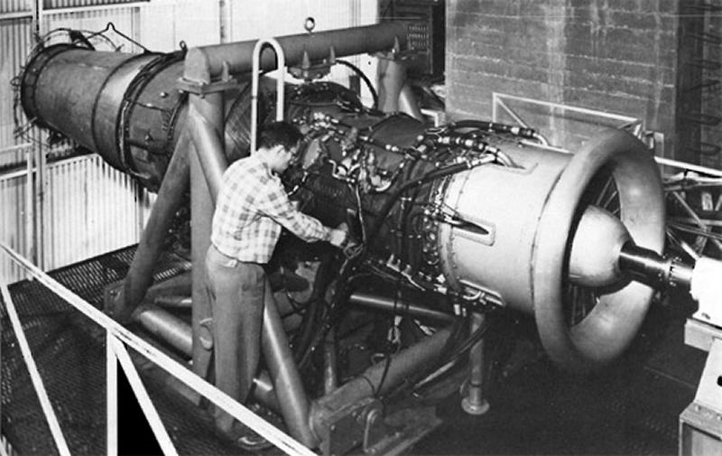 |
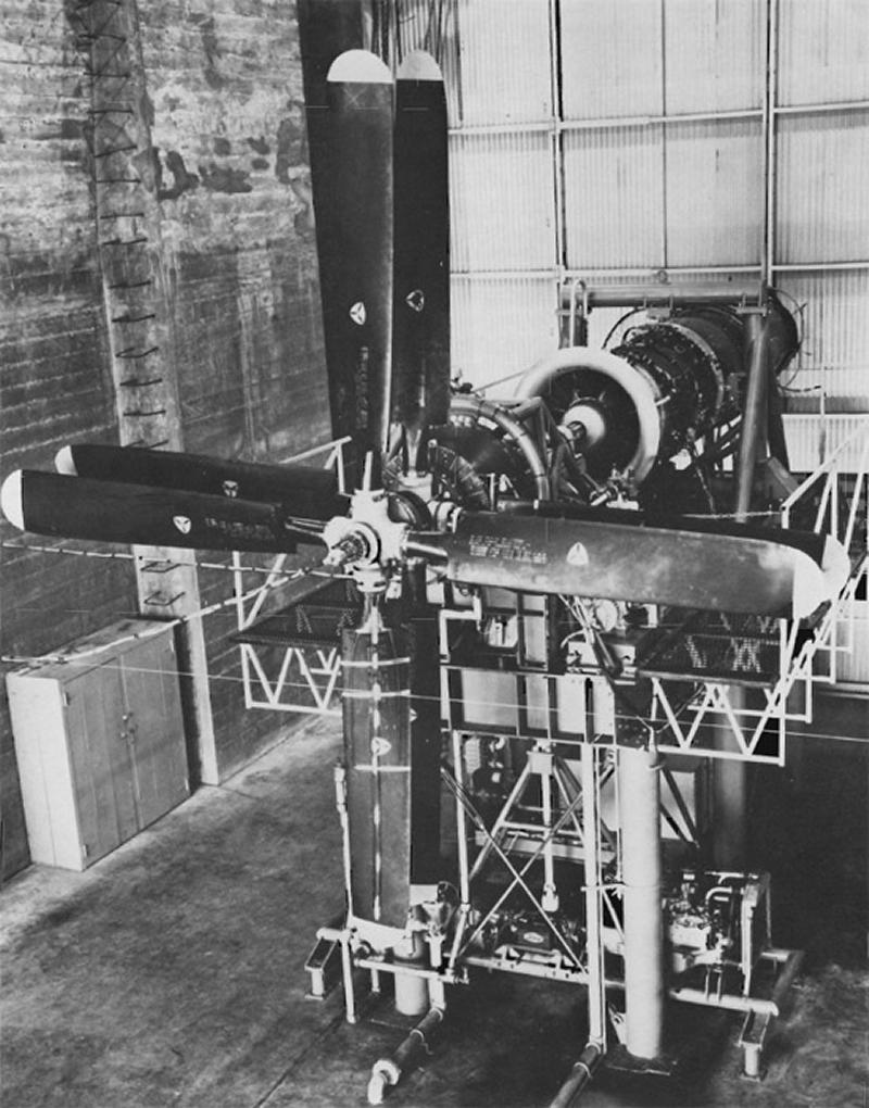 |
| Northrop XT37 Open and Under Test. It has again taken on more of the characteristics of a modern gas turbine, particularly with the can-annular combustion section. | ||
17 Sep 1945. ATSC informed Northrop Aircraft that J.C. Franklin, Transcontinental and Western Air, Inc. Engineering Vice-President had been given permission to contact Northrop Aircraft and receive Turbodyne I performance data.
26 Dec 1945. Dr. Rannie sent Phelan a memorandum regarding stage-by-stage tests of the Turbodyne compressor. This action was representative of the wild requests Northrop Aircraft encountered as the Turbodyne was developed and ATSC no doubt became impatient with the methodical stage-by-stage tinkering with blade angles, etc. ATSC Capt Barfield had asked about the possibility of building up the Turbodyne compressor stage by stage with the turbine supplying power, thinking this would be the best way to match compressor stages. Dr. Rannie pointed out that it would be necessary to start with at least five or six stages in order for the Turbodyne to be self-sustaining. It was unlikely that equilibrium running conditions would correspond to the design flow rate for a small number of stages. The date for running the completed unit would be postponed.
The planned program had considerable flexibility with the blade-angle adjustment scheme previously proposed that used static pressure readings as a measure of merit. Although the then-current program had no provision for substitution of blades with different twists, but ANY program involving blade design and fabrication based on stage-by-stage tests would be a lengthy endeavor. At that time, turbine design seemed more questionable and the first changes would probably be to the turbine. Hence, testing the entire unit would be the only means to produce the desired information. Stage-by-stage compressor testing might be valuable if an adequate (4,000 to 5,000 hp) independent power source were available. Northrop Aircraft felt stage-by-stage testing inappropriate at that time.
4 Jan 1946. Phelan sent the ATSC a print of the latest XT37-1 reduction gear study with gear tooth loading, pitch line velocities, bearing loads, etc.
21 Jan 1946. Phelan informed ATSC that in the absence of final approved specifications covering the XT37-1, Northrop Aircraft was designing to the tentative Specification XS-28602, specifically:
D-9 Gyroscopic Forces – The unit shall withstand for at least on minute, gyroscopic torque imposed at its rated speed and at a three radians per second precession.
D-12c. The engine mounts shall be capable of withstanding an ultimate 12g loading and a 3g side load.
22 Jan 1946. ATSC wrote Northrop Aircraft, directing that in order to select an appropriate propeller, the latest Turbodyne performance data be sent to Hamilton Standard, Curtiss-Wright and Aeroproducts.
6 Feb 1946. ATSC wrote Northrop Aircraft concurring with the Northrop Aircraft position on stage-by-stage compressor testing and agreeing that for the time being, use of Specification No. XS-28602 was acceptable.
March 1946. Several Cross Reference and Suspense Records mention Fredrick Flader, Inc. of Buffalo, NY. Apparently, the ATSC was using Flader to review Northrop Aircraft reports, calculations, and theoretical treatises on the XT37 compressor and control system. This process involved Flader having access to Northrop Aircraft intellectual property, which today would probably be considered a conflict of interest. Frederick Flader, Inc. had been chosen to develop the XT33-FF-1, a 6,800 lbT axial-flow turboprop during 1944 and the XJ55-FF-1, a small-diameter turbojet intended for auxiliary power or as a drone power plant in 1946. Both projects were cancelled. The XJ55's claim to fame was its supersonic axial-flow compressor, a concept that never achieved its theoretical potential.
4 Sep 1946. Phelan wrote Col R.J. O'Keefe, Power Plant Laboratory Propulsion & Accessories Subdivision Acting Chief regarding gas turbine control development, specifically the XT37. Northrop-Hendy had hired the Eclipse-Pioneer Division of Bendix Aviation Corp to develop its control system. Northrop-Hendy and Eclipse saw turbine temperature management as the most critical control parameter. This value could be measured directly or approximated from gas stream entering the nozzles or tail pipe temperature, and could be calculated from compressor discharge temperature and fuel/air ratio. The last method required a mass airflow computer, and developing such an instrument that was simple and accurate was exceedingly difficult. Hence, direct temperature measurement was chosen for primary control, but mass airflow instruments such as the hot wire type might be suitable for emergency controls. Direct temperature measurement was generally the preferred method of turbine temperature control. Such a control system would benefit from better understanding of turbine blade time/temperature response to varying temperatures, pressures and velocities. The behavior of thin sections, such as blade trailing edges, versus more massive sections, would also be helpful. The setup and instrumentation for such testing could be better and more economical if available to the entire industry than if each manufacturer made its own. [Author's note: The British National Gas Turbine Establishment was created for this exact reason.]
20 Sep 1946. Phelan wrote the ATSC complaining that while Northrop Aircraft had originally planned to design the XT37-1 starter, the ATSC had assigned that task to Victory Engineering Company of Newark, New Jersey more than six months prior. Since XT37-1 testing was to begin in about 90 days, and since Northrop Aircraft had heard nothing further about the starter, Northrop Aircraft was seeking permission to contact Victory Engineering for a progress report. At least three of these starters would be required. This request was forwarded to the Equipment Laboratory for action. On 14 Oct 1946, the Equipment Laboratory indicated that the latest Victory Engineering delivery schedule was for some time in December 1946, contingent on a slight modification that had become necessary during testing. All parts were in the final fabrication and finishing stages except for the propellant chamber, which was scheduled for delivery by the Bethlehem Steel Company between 15 and 30 Oct 1946. The Victory Engineering contract called for three starters, one of which would be life-tested to destruction. If initial tests were satisfactory, the Equipment Laboratory would initiate action to supply Northrop Aircraft with a third starter. The Equipment Laboratory granted Northrop Aircraft approval to directly contact Victory Engineering. Northrop Aircraft was notified of all this on 18 Oct 1946, along with permission to directly contact Victory Engineering.
27 Sep 1946. Col R.J. Minty, the new Power Plant Laboratory Chief, informed Northrop Aircraft that Curtiss-Wright had been given clearance to visit Northrop Aircraft, discuss the XT37 and receive XT37 data. [Author's note: Once again, the Curtiss-Wright XT35 was in direct competition with the XT37; was this a conflict of interest?]
14 Oct 1946. Aeroproducts was granted permission to contact and receive data from Northrop-Hendy and Eclipse-Pioneer relative to development of an XT37 propeller.
18 Oct 1946. Very late in 1945, the process of obtaining and distributing captured German technical information began. Among those gathering information was the U.S. Naval Technical Mission, which announced it had secured several reports on axial-flow compressors and gas turbines. Northrop Aircraft became aware of these and forwarded a request for copies via Col Keirn.
[Author's note: the starry-eyed 0.4 lb/hp/hr specific fuel consumption metric was never achieved; what saved the day was in-flight refueling, which first started to appear in late 1948.]
| Efficiency (%) | SFC | ||||
|---|---|---|---|---|---|
| Config | Unit | Comp | Turb | Modification | (lb/hp/hr) |
| 1 | L-1 | 84 | 85 | First Unit (Baseline) | 0.520 |
| 2 | L-4 | 86 | 88 | Fourth Unit | 0.448 |
| 3 | L-4 | 86 | 88 | Config 2 with extra comp stage, higher comp ratio, 10% power increase | 0.425 |
| 4 | L-4 | 88 | 91 | Config 2 with development | 0.402 |
| 5 | L-4 | 86 | 88 | Config 2 with heat exchanger | 0.395 |
| 6 | L-4 | 87.5 | 90.5 | Config 2 with development, extra comp stage, higher comp ratio, 10% power increase | 0.396 |
| 7 | L-4 | 87.5 | 90.5 | Config 6 with stator blade intercoolers | 0.388 |
| 8 | L-4 | 87.5 | 90.5 | Config 7 with turbine blade cooling | 0.384 |
| 9 | L-4 | 87.5 | 90.5 | Config 8 with heat exchanger | 0.362 |
The table showed several practical SFC reduction strategies, and Northrop Aircraft thought continued developmental improvement was the most logical strategy. An important gas turbine characteristic often overlooked in arbitrary comparisons to reciprocating engines on the basis of SFC only was that the XT37-1, designed to deliver 4,000 shp at 35,000 ft could produce 9,000 to 10,000 shp at sea level. In the XB-35's case, the takeoff power available was limited to about 7,000 shp strictly due to reduction gear weight considerations. Further XB-35 studies indicated that reciprocating and turboprop engine takeoff distances limited gross weights, while the fuel volume available limited turboprop installations. Additional turboprop advantages accrued with the higher operating speeds for maximum range.
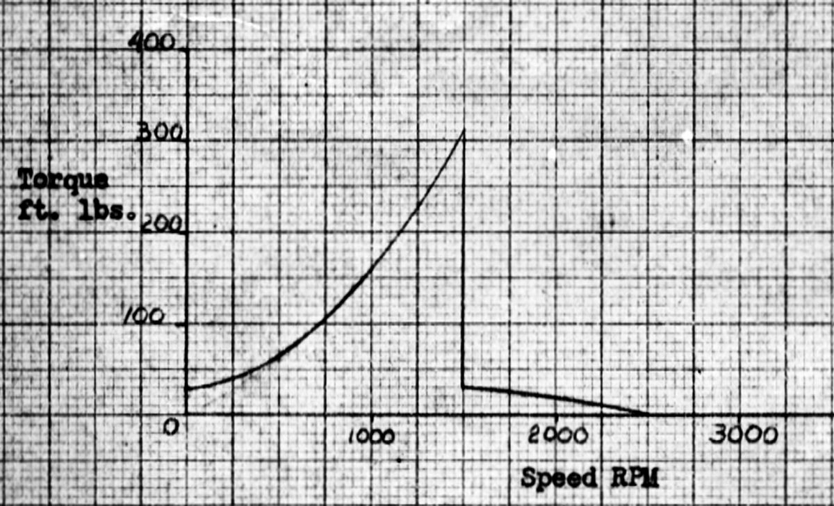 |
| XT37-1 Starting Torque |
25 Nov 1946. So that the AAF could effectively develop starters and generators for the XT37-1, Col Minty requested starter data consisting of the complete turboprop moment of inertia, propeller moment of inertia, propeller reduction gear ratio, torque versus rpm curve during starting, starter mounting pad and drive drawing, and starter drive ratio. For the generator, Col Minty requested drive and pad configuration, drive rating, gear ratio, idle rpm, cruise rpm and maximum rpm. Northrop Aircraft replied on 4 Dec 1946 with the following:
Turbine and compressor rotor, reduction gear and accessories moment of inertia = 1,140 lb ft²
Propeller moment of inertia = 6,080 lb ft²
Turbine to propeller gear ratio = 1:0.126
Starter mounting pad and drive type = AND10002 Type V
Starter drive to turbine ratio = 1:1
Generator drive and pad configuration = AND10002 Type IIA
Generator drive rating = see specification
Generator to rotor gear ratio = 1.16:1
Idle rpm = 3,500
Cruise rpm = 6,750
Maximum rpm = 7,088
12 May 1947. XT37-1 project report. Northrop Aircraft decided to install the first four compressor stages using parts intended for the second unit and conduct tests to determine airflow characteristics through that compressor section.
9 Jul 1947. PPL informed Northrop-Hendy that Maj Gen Powers had recently completed a tour of European turboprop and turbojet development establishments and would be at Wright Field on 17 Jul 1947 to complete his mission comparing European and American engine development. PPL requested that Phelan be available with XT37-1 drawings, photographs and data that would adequately explain the present Northrop-Hendy development status.
13 Aug 1947. ATSC granted clearance for McDonnell Aircraft Corporation to receive XT37-1 data from Northrop Aircraft for use in preparing an AAF aircraft proposal. Similar permission was granted on 2 Sep 1947 for Consolidated Vultee, which was preparing a Navy aircraft proposal.
Contract Termination Threatened
22 Sep 1947. Commanding Gen N.F. Twining informed Jack Northrop that a decrease in the AMC engine development budget made it necessary to evaluate all then-current engine developments and determine which warranted continuation. XT37 development was not to be continued beyond funds already committed by Contract W33-038-ac-6218. The AMC wanted to carry the XT37 project as far as possible with the remaining funds and obtain as much test data as possible. Following that, present Northrop Aircraft and Northrop-Hendy facilities would be carried as an engine development or production facility. In order to utilize the remaining funds in the best possible manner, Gen Twining requested that Northrop Aircraft prepare recommendations for a revised test program. This letter initiated a protracted exchange, which will now be summarized; the narrative will then continue with XT37 development correspondence beginning 23 Sep 1947.
On 13 Oct 1947, Jack Northrop responded to Gen Twining.
This letter resulted in comments that are undated and unsigned:
Paragraph 5. The Turbodyne I, for which the Navy and USAF had expended $2,400,000 was not mentioned. While this was a smaller engine, it did use an axial-flow compressor and produced much valuable background information, which was considered in granting the present contract.
Paragraph 7. It was doubtful that the $3,500,000 mentioned would complete a type test, as a proposal was already at the AMC for $1,500,000 to complete a 50-hour flight qualification test, which was not the 150-hour test Mr. Horner mentioned. AMC estimated that a complete accounting of all funds to complete the 150 hour test would be:
Turbodyne I Background = $2,400,000
Current Contract = $3,700,000
50 Hour Test = $1,500,000
150 Hour Test = $1,000,000
Total = $8,600,000
Current and proposed Northrop Aircraft contracts were CPFF and there had been large overruns. Considering development time, the first Turbodyne I contract was signed in August 1941, making the Turbodyne development contract longer than any other American manufacturer.
16 Dec 1947. Maj Gen F.O. Carroll, USAF Research and Development Director penned a review of the entire propulsion development program to the USAF Chief of Staff. He noted that the Navy and USAF collectively had 8 turbojet engines, 9 turboprop engines, 21 liquid-propellant rockets, and 20 ram- and pulse-jet engines under development. Of these, the USAF had 5 turbojets and four turboprop development projects, which were the subject of the letter.
| USAF Engines | US Navy Engines | ||||||||||||
|---|---|---|---|---|---|---|---|---|---|---|---|---|---|
| Equivalent Shaft HP | SFC | 35,000 ft Cruising 500 mph | |||||||||||
| Engine | 50-hr Test | 1948 Cost | 1949 Cost A. $170 M B. $212 M | Sea Level Static Takeoff | Sea Level Military 500 mph | 35,000 ft Normal 500 mph | 35,000 ft Cruising 500 mph | 35,000 ft Cruising 500 mph | Spec Wt | Spec Vol | Spec Area | Engine | Sea Level Takeoff EHP |
| T37 | Oct 1949 | $3,727,730 | A. None B. None | 8,400 | 11,150 | 5,150 | 5,150 | 0.44 | 0.98 | 1.72 | 2.07 | Chrysler XT36-D-2 | 1,144 |
| T45 | Oct 1949 | $900,000 | A. $4.000 M B. $5.225 M | 12,500 | 13,500 | 6,600 | 6,600 | 0.40 | 0.91 | 2.38 | 1.98 | De Laval XT42-DL-2 | 3,992 |
| T35-3 | Apr 1950 | $21,752,420 | A. $3.180 M B. %5.180 M | 9,500 | 8,800 | 5,700 | 5,700 | 0.43 | 0.98 | 2.83 | 3.33 | Pratt & Whitney XT34-P-2 | 4,100 |
| T39 | Jan 1951 | $3,180,000 | A. None B. 1,545 M | 9,550 | 11,700 | 6,050 | 6,050 | 0.61 | 0.61 | 1.65 | 1.48 | Allison XT40-A-4 | 5,432 |
| A = Salaried; B = Hourly | Ranger XT46-R-2 | 9,850 | |||||||||||
| Engine Priority | Turboprop Priority | Turbojet Priority |
|---|---|---|
| 1. Curtiss-Wright T35-3 | 1 | |
| 2. Pratt & Whitney T45 (or 9,000 to 10,000 lbT turbojet) | 2 | |
| 3. General Electric J53 | 1 | |
| 4. Larger Lockheed J37 (9,000 to 12,000 lbT) | 2 | |
| 5. Packard J49 | 3 | |
| 6. Allison J33 | 4 | |
| 7. General Electric J47 | 5 | |
| 8. Allison T39 | 3 | |
| 9. Northrop Aircraft T37 | 4 |
Since five to seven years were required to develop an engine through 150 hour type test, advanced tactical aircraft and guided missile power plant planning was required so that propulsion was available when needed. Such planning had not existed previously, forcing the USAF to concurrently develop many engine types and ratings. This has resulted large expenditures for engines that were ultimately not used and crash developments for engines urgently needed. A five-year plan was being formulated to clarify future engine development. The unanticipated emphasis on the Boeing B-52 had resulted in 60% of FY 1947 engine funds being spent on turboprop development, mostly with the Curtiss-Wright XT35, which created prejudices toward other engine development. If current trends continued, future emphasis would be on high speed with fuel consumption problems addressed by in-flight refueling, resulting in a shift to turbojets. Continued development of all power plants and related items was expected to cost $50 million in FY 1949, with $29 million for gas turbines alone. Even this amount would not permit competitive development in all power plant categories. It appeared that only $34 million would be available in FY 1949, making it necessary to prioritize development activities.
The 22 Sep 1947 letter to Northrop Aircraft, Northrop Aircraft's answer, and AMC's comments were referenced. Funds were available to support Northrop Aircraft's laboratory tests through 30 Jun 1948, and Northrop Aircraft had submitted a proposal on 18 Nov 1947 to conduct 50-hour flight qualification tests for an additional $1,449,084.55, to be completed by 1 Jul 1949. If the Medium Bomber competition specified the XT37 as an alternate and if it provided sufficiently improved performance, XT37 development would proceed; otherwise additional funds were not contemplated.
Northrop Aircraft's viewpoint and arguments were sufficiently logical and factual, AMC agreed with many of their points, and would have preferred to keep the development alive, irrespective of the Medium Bomber competition outcome. However, the AMC did not agree that Northrop Aircraft had designed and tested a 7,000 shp gas turbine in 3.5 years at a cost of $3.5 million, which was 1/3 to 1/4 what was usually required. AMC also did not agree that the XT37 was the best available turboprop unless its operating temperature was increased above the original design or any value achieved to date.
The primary difference between Northrop Aircraft and AMC views centered on the importance of development facilities for long-range continued power plant development. AMC believed that contractors with great development facilities produced the best engines. If only time and cost were considered, a contractor without development facilities could quickly and economically fabricate an engine. However, this only started the process; extensive, costly and time-consuming component testing was required for a really good engine. Northrop Aircraft and Northrop-Hendy lacked this infrastructure and only significant government investment could provide it.
The Allison T39 was originally a much larger engine, but Allison believed the mechanical problems of a 14,000 hp engine and possible weight increases made the then-current size attractive to aircraft builders. If, as a result of the five-year plan, the concentration should be on turbojets, then it would be advisable to request Allison to develop those components contributing to a turbojet and reduce turboprop emphasis.
It was recommended that the AMC be furnished the advanced tactical planning and that AMC's proposed action to discontinue the Northrop Aircraft power plant be approved by Headquarters, USAF or an alternate decision furnished; it was also recommended that final approval of the five-ear plan be given to emphasizing the development of turbojet components rather than an Allison T39 turboprop series.
The Curtiss-Wright T35-3 engine had first priority because of the Boeing B-52's importance. Regardless of future B-52 plans, it was urgently recommended this engine's development be continued for future large-cargo applications, and possibly high-speed bombers, if acceptable propeller efficiencies arise. The reduction gear and control system problems and the requirement higher component efficiencies make turboprops difficult to develop. This engine was then in undergoing experimental test flight and component test facilities were producing valuable information.
The Pratt & Whitney T45 engine had second priority because of its competitive position to the Curtiss-Wright T35 in the B-52. When first discussed with P&W, it was agreed that this engine would be designed to be convertible to a 9,000 lbT turbojet, if required. P&W had a background of a 4,100 takeoff hp turboprop built for BuAer that was then operating and scheduled for a 50-hr test during summer 1948. Development facilities were available and extensive additions were being built.
The General Electric J53 is in third position because a large turbojet for use at higher speeds was needed. GE was investigating constructing this engine for a range of aircraft and missile speeds from high subsonic through transonic and into the supersonic range. J33 and J35 that powered then-current tactical jet aircraft were originally designed by GE. Others, notably Allison, have contributed extensively to initial design, development and manufacture. GE had excellent development facilities.
The enlarged Lockheed J37 held fourth position because of its unique design features. Curtiss-Wright's Wright Aeronautical Division was being contracted to evaluate J37 components because it had development facilities that permitted full-load sea-level independent compressor and turbine testing. These tests will lead to a decision as to whether the J37 should be subsonic or supersonic, and whether an enlarged version could be designed.
The Packard J49 occupies fifth position because it is a ducted fan engine, the only such type under U.S. development. Ducted fans offered both turboprop and turbojet advantages, having a takeoff thrust similar to the turboprop and better fuel consumption than the turbojet. This was deemed particularly important to the high-speed bomber, and warrants continuation. Packard had very good development facilities in Toledo, Ohio.
The sixth-place Allison J33 because like the Curtiss-Wright T35, it incorporated a centrifugal rather than axial compressor, and could be increased to 10,000 lbT with water injection. The centrifugal compressor offered a much-simplified production. Only limited development facilities were available, but Allison had extensive manufacturing background and facilities.
The General Electric J47 was in seventh place because it was the largest turbojet then entering production and an improved model offered the possibility of over 10,000 lbT within two years.
The Allison T39 was in eighth place because a turboprop engine's importance was uncertain and Allison's inferior component testing capability was suspect. BuAer had contracts with Allison for a smaller turboprop involving about four times the funds then in the T39 contract.
The Northrop Aircraft T37 ranked last largely because Northrop Aircraft did not possess the extensive development facilities available to conduct a long-range program, and did not have plans to provide them. The XT37 had operated at 5,000 shp on the test stand and Northrop Aircraft had presented data indicating that planned turbine operating temperature increases equivalent to the Curtiss-Wright T35-3 could equal that engine's power. The important difference with Northrop Aircraft's conclusion is that the T35 was designed and had operated at higher temperatures because of a turbine air-cooling scheme for the turbine wheels and blade roots. Conversely, the T37 had been designed to operate either in a tractor or pusher configuration, a feature that if incorporated into the T35 would require 2.5 years and 3.5 to 4.0 million dollars.
In addition to the engine listed, there was a future requirement for very large supersonic turbojets operating at Mach 1.6 and developing 9,000 to 10,000 lbT at 50,000 ft. This was needed for the WX-775B (the Northrop Aircraft supersonic surface-to-surface missile (XSSM-A-5 Boojum). Again, the fundamental question was whether Northrop Aircraft, with its limited development facilities, undertake these projects.
All four USAF and one Navy turboprop projects were essentially the same 9,000 to 12,000 shp power class. The USAF believed this size would be most useful for long-range aircraft. The largest turboprop that could be developed was unknown. Turbojet engine being developed ranged from 5,000 to 20,000 lbT.
20 Oct 1947. Col Minty cabled the Los Angeles AAF Procurement Field Office requesting lowest XT37 SFC and power output during these conditions. The reply on 23 Oct 1947 stated the XT37 SFC was 0.972 at 5,100 ehp and 7,088 rpm with 1,360°F turbine inlet temperature.
3 Nov 1947. Northrop Aircraft requested permission to manufacture reduction gear unit with a SAE 60-80 or 60L-80 propeller shaft in order to use XB-35 propeller on the XT37-1 engine.
18 Nov 1947. Northrop-Hendy sent AMC a proposal to provide an XT37 engine and perform a 50-hour qualification type test in accordance with AAF Specification No. XB-28649 dated 14 Feb 1947. The engine was to be built from components designed under Contract W33-038 ac-6218. Estimated cost was $1,449,084.55, with completion 15 months from authorization to proceed, not later than 1 Apr 1948. Northrop-Hendy wanted this to be a CPFF contract.
26 Nov 1947. Northrop Aircraft representatives F.H. Quayle and D.V. Collins requested that the Propeller Laboratory (hereinafter PropLab) supply Northrop Aircraft with a dual-rotation propeller for XT37-1 test stand running. This propeller should absorb up to 11,000 shp under sea level conditions at about 844 rpm, be usable with an AN 60L-80 shaft, be controllable, and be available by 1 Nov 1948.
| Manufacturer | Hub | Shaft | Blade | Blades | Diameter |
|---|---|---|---|---|---|
| a. Hamilton Standard | 826080 | 60-80 | 2015-0 | 8 | 15'0" |
| b. Hamilton Standard | 826080 | 60-80 | 2F17-6 | 8 | 16'7" |
| c. Aeroproducts | AD8684FN | 60L-80 | C40-216-18 | 8 | 16'6" |
| d. Aeroproducts | AD8664FN | 60L-80 | C40-216-36 | 6 | 15'0" |
| e. Hamilton Standard | 8260L80 | 60L-80 | 2H17-6 | 8 | ≤ 16'6" |
On 19 Jan 1948, the PropLab reported that only five propellers could be considered for this application; none met all requirements. Propellers a and d would have to operated in a stalled condition to absorb the power and would probably experience structural difficulty. Propellers b, c and e could not meet the delivery date. Propellers a and b had the wrong shaft size. The Hamilton Standard 826080 hub could be modified to accommodate a 60L-80 shaft at some expense. If this were done, propeller a would probably be available by November 1948. The 2F17 blades would probably be available by Spring 1948, thus converting propeller a to b and permitting use at 11,000 shp with reasonable safety. The 82600L80 hub would not be available until summer 1949 at the earliest. The Aeroproducts 8-blade propeller would not be available until early summer 1949; the 6-blade propeller could probably meet the Nov 1948 date if the Navy could obtain the propeller. BuAer later said that propeller availability would not be improved by making them government furnished.
The PropLab suggested considering using a 60-80 shaft for testing using propeller a and later b at no great expense to the government. A 60L-80 shaft would still be required for flight. If the 60-80 shaft was acceptable, the PropLab would arrange its supply to Northrop Aircraft.
On 1 Mar 1948, Northrop Aircraft wrote AMC informing them that it had decided to design its reduction gear with a 70-90 propeller shaft, but that during testing it would install a 60-80 shaft and use propeller a, later to be converted to propeller b. The gear box would be capable of using the largest and heaviest propeller that could be mounted on a 70-90 spline. Northrop Aircraft wanted to modify the request for a propeller that could absorb up to 10,000 shp at approximately 930 rpm. Northrop Aircraft stated it could use the propeller in April 1949 and expected AMC to supply the blades that would convert propeller a to propeller b.
9 Mar 1948. Northrop-Hendy had recently submitted Northrop-Hendy Specification No. NHS-101, which apparently covered the XT37-NA-3 flight unit. Col Minty sought the PropLab's comments so the specification could be approved, changed or disapproved. On 26 Apr 1948, the PropLab responded that using the T37 in an airplane meeting the requirements of MX-948 (General Research on Bomber Aircraft) would require an 18-foot diameter 8-blade dual rotation propeller to obtain good propulsive efficiency. Such a propeller would operate at about 700 rpm, would weigh about 2,300 lb, would have a 400 slug ft² polar moment of inertia per rotating element (4 blades) and would produce about 24,000 lb static thrust. If the T37 were used on a slower (i.e., transport) aircraft, the propeller diameter might approach 20 feet, the polar moment of inertial would be about 600 slug ft² per rotating element and the static thrust would be about 30,000 lb.
At 930 propeller rpm the diameter would be limited to about 15 feet on a MX-948 type aircraft to avoid compressibility losses. Such a smaller propeller would lose about 15% static thrust and 2 – 3% cruise efficiency. Development of a No. 70-90 shaft size would be mandatory for the T37-NA-3. The gear box would need to be designed with a negative thrust value equal to the positive thrust values given above.
The PropLab suggested that NHS-101 be revised as follows:
a) Add, as a second sentence in section E-60(2). Oil Leakage – "This shall not include more than one ounce per hour at the nose-to-inboard shaft seal and one ounce per hour at the seal between the shafts."
b) In section E-12b, increase propeller weight to 3,000 lb and define polar moment of inertia value as 600 slug ft² per rotating element.
c) In section E-22a, replace "60L-80" with "70-90"; delete sentence "It is desirable … etc."; add tractor application; and replace ".125:1 to .135:1" with ".1025:1 to .091:1".
d) Add another paragraph in section E-22a:
The propeller shafts shall each withstand, without permanent deformation or failure, a vibratory loading of propeller rotational speed frequency as represented by a bending moment of 350,000 in-lb. This is in addition to other loading stated in this specification. The outboard propeller shaft shall deflect no more than 0.5° at any location of the propeller intermediate bearing support.
If the T37-3 was to be installed in an airplane where the propeller diameter was limited, such as a modified YB-49, the use of a 70-90 shaft would probably not be required and a 60L-80 shaft size may be adequate up to 16-foot diameter. In addition the propeller rpm could be as high as 850. However, this would not be an optimum propeller installation.
On 8 Feb 1949, AMC notified Northrop Aircraft that it would be unable to supply propellers according to the agreed-upon schedule. Conversion, delivery and vibratory stress surveys had been delayed.
17 Mar 1948. Col Minty authored an XT37 status report. There were then two operable XT37s; the most recent modification was the addition of two compressor stages, making 14. This modification was to more closely match the compressor and turbine, which was achieved by raising the loaded compressor efficiency from 81% to 86%. A program was under way to decrease the turbine stages from three to two; blading and disks for this were on order, and using the new turbine was expected to give 10,000 shp plus 2,300 lbT at sea level static, as per Northrop-Hendy Specification No. NHS-102. The 14-stage compressor, with individual combustion chambers, and three-stage turbine, had been operated at 6,850 eshp with a 0.78 lb/lbT/hr SFC. The turbine inlet temperature was 1,520°F. This power reading was suspect because the test stand torquemeter was against the stops, making the output higher than indicated; shop air pressure at the time was not sufficient to balance the torque arm. Northrop Aircraft stated that the turbine was slightly low as the rotor once rubbed against the stator, making the tip clearance excessive. This would affect the power output and SFC. To the PPL's knowledge, the compressor efficiency was the best yet demonstrated on any engine with equivalent pressure ratio. The two engines then on contract were strictly laboratory engines; they were not equipped with propeller reduction gear, or accessory drives and were of heavy construction. The reduction gear, although contracted, was not yet built. The high weight could be eliminated by using aluminum casings and the two-stage turbine. The control system, though bench tested, had not been operated on an engine.
13 Apr 1948. In a Northrop-Hendy letter covering transmission of a revised Specification No. NHS-102, we find a new title and company designation: Model Specification, Engines; Aircraft Turbo-Prop: XT37-NA-3; Northrop-Hendy Co. Model F-5 – TURBODYNE.
19 Apr 1948. D.A. Dickey, Engineering Division PropLab Chief, notified Northrop Aircraft that the AMC would furnish a Hamilton Standard 826080 propeller hub with 15-foot 2015-0 blades; 2F17-6 blades would follow at a later date. The PropLab was concerned about the reduction gear ratio choice and was preparing separate correspondence addressing this. PropLab requested a test stand general arrangement drawing since a vibratory stress survey would be required to identify interactions between the propeller and test stand. The contemplated configuration (tractor/pusher) was also requested. Phelan responded on 22 Apr that the test stand arrangement for use with gear box and propeller had not been drawn, but would be forwarded when available.
6 May 1945. Col Minty produced an analysis of the Northrop Aircraft "High Through Flow" Engine, a design resulting from preliminary studies conducted on a contract to Northrop-Hendy under the Northrop Aircraft guided missile program, which was presented to the Engineering Division in Report No. GM715 and in conferences in 21 and 22 July 1947. Brig Gen D.L. Putt and Maj Gen Craigie directed the PPL to obtain an unbiased evaluation of the engine from a recognized turbomachinery expert. An earnest effort was made to obtain such an evaluation, but of four known unbiased authorities only one is willing to undertake such an evaluation. On 20 Nov 1947, Dr. Arthur Kantrowitz of the Cornell Graduate School submitted an $8,000 quotation, but the PPL had no funds with which to cover this. By the time funds became available, the Procurement Division processed the purchase request and obtained a secrecy agreement from Kantrowitz, another quotation raised the cost to $9,005; the PPL had no funds to cover the increase and opined that such an evaluation could not be completed in time to be of much benefit. Meanwhile, Opie Chenoweth contacted Dr. Frank Wattendorf, who was in good health, apparently working for the AMC, and willing to undertake the evaluation. The PPL suggested that Wattendorf do the evaluation so that FY 1949 funds could be allocated as appropriate. Wattendorf thought he could render an opinion in a few weeks, to be followed later by a formal report. On 15 May 1948 Brig Gen Putt reiterated that an evaluation was still desired, but concurred that negotiations with Dr. Kantrowitz be terminated. He suggested that the PPL contact the NACA and try to obtain temporary services of one or two qualified persons to assist Dr. Wattendorf, who was receptive to the plan.
13 May 1948. Col Minty, having received a proposal from Northrop Aircraft for a T37 through 50-Hour Qualification Test estimated to cost $3,700,000 including extension shafts for YB-49, dual rotation gearboxes and two engines for AMC tests, planned to prepare a purchase request. The Northrop Aircraft Air Force Representative had seen the engine run at 7,300 rpm.
14 May 1948. Northrop-Hendy sent Opie Chenoweth two reports:
R-87 Combustion Chamber for Turbodyne II (XT37-1) Units L-1 and L-2, Individual Cylinder Type dated 3 Feb 1947 – Copy # 13.
R-90 Combustion Chamber for Turbodyne II (XT37-1 Unit L-3, Annular Type dated 11 Apr 1947 – copy # 13.
17 May 1948. Col Minty cabled the Wright Aeronautical Corporation (WAC) asking if Mr. Kennedy would be available on 20 or 21 May 1948 to discuss XT37 reduction gearing. WAC cabled back agreeing to either day with Thursday 20 May being best.
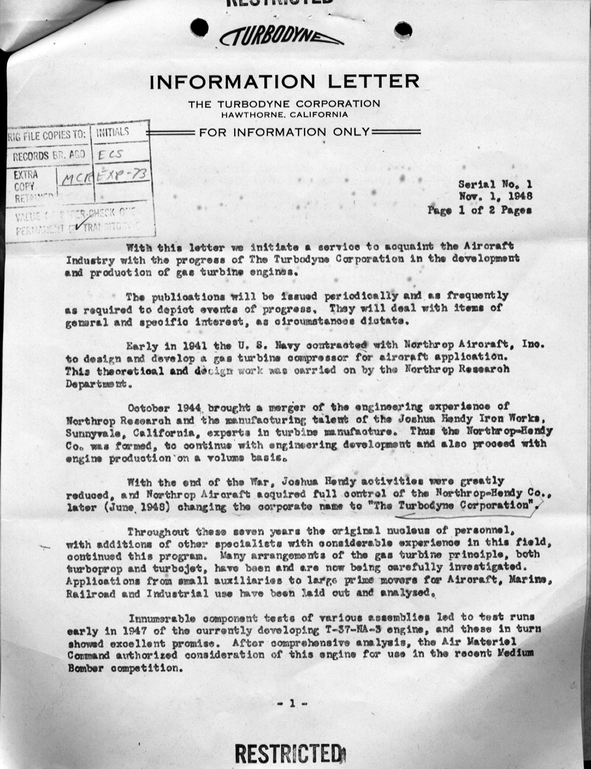 |
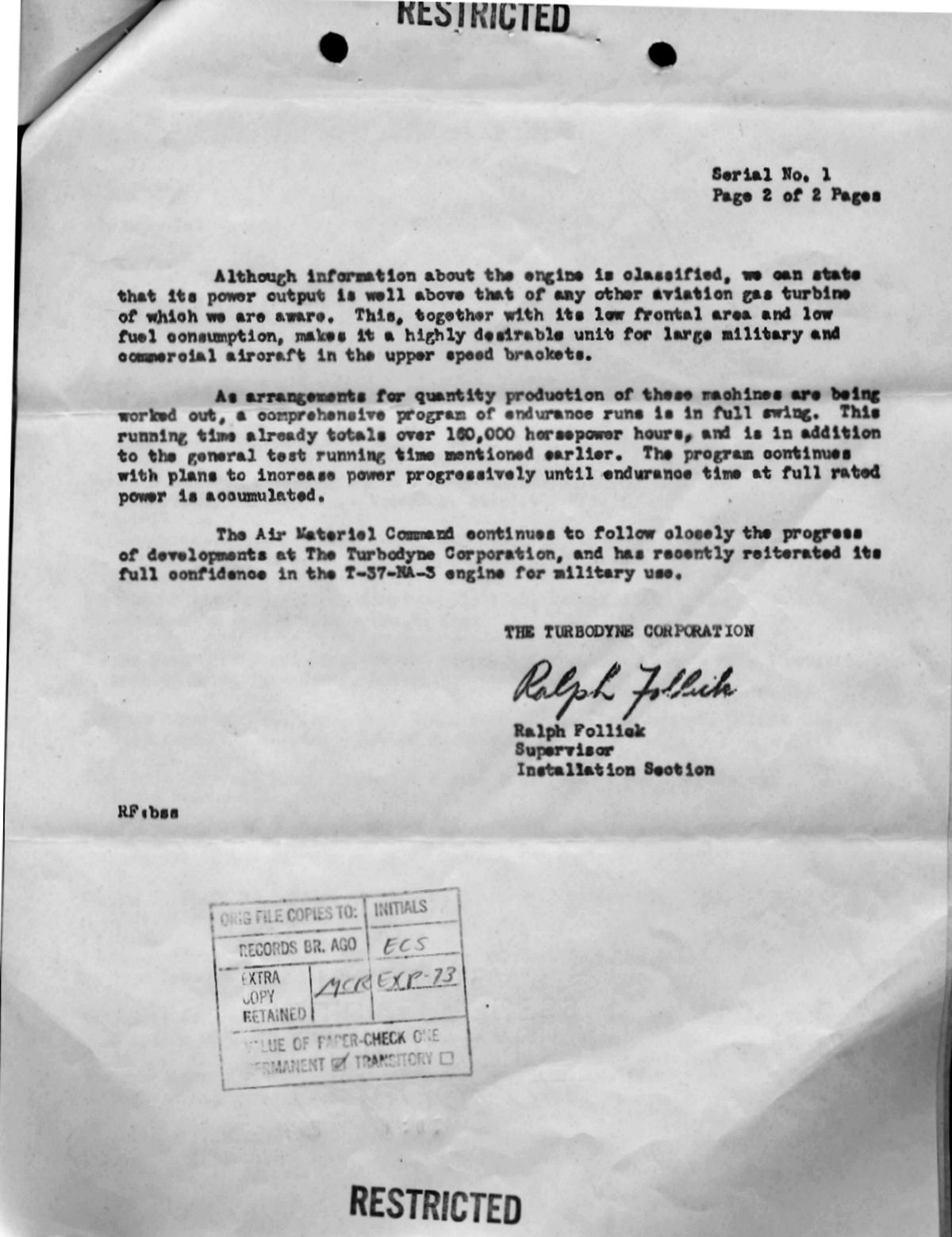 |
| Turbodyne Corporation Information Letter No. 1 |
|
The Joshua Hendy Iron Works was sold to Westinghouse during 1947. The Northrop-Hendy Co. became the Turbodyne Corporation in June 1948 to continue XT37 development. T.H. Quayle was President and A.J. Phelan was Vice President and Chief Engineer. On 19 Oct 1948, we see the first Turbodyne Corporation correspondence. Phelan proposed to initiate a "Restricted" monthly publication for limited distribution to the aircraft industry describing XJ37-NA-3 progress, as well as other similar projects. Early issues were to be of a general nature, with succeeding ones more detailed. Phelan enclosed a sample, a proposed distribution list, and requested AMC's comments and suggestions. Col Minty approved the information letter content on 8 Nov 1948, but the distribution list could not be fully approved. Information to the CAB and CAA had to be released through the Chief of Staff, some companies either had not renewed or did not have security agreement and could not receive classified information, but some of these were Navy contractors. Col Minty suggested sending the list to BuAer for its approval.
19 Oct 1948. Chandis H. Brauchler, Vice President of the Canton Drop Forging and Manufacturing Company of Canton, Ohio, wrote Col Minty regarding hot-spin testing of turbine wheels. Canton had forged two turbine wheels, one normally used type 19-9DL alloy (10% chromium, 9% nickel), and one alternate type 16-25-5 alloy (16% chromium, 25% nickel, 6% molybdenum). The first wheel was forged early in 1948, but Turbodyne Corporation held up its completion after ultrasonic inspection identified some non-metallic inclusions. A thorough survey was made of the wheel using highly-sensitive ultrasonic inspection equipment, which accurately located and recorded the locations and sizes of the imperfections. Since it was practically impossible to furnish steel of the size required for turbine wheels that was completely free of non-metallic inclusions, some means of qualifying ultrasonic indications was necessary. Brauchler had requested that the NACA perform a hot-spin test on the wheel to see whether it met service requirements, but the NACA was reluctant to do such testing for private industry. However, Canton believed that such tests yielded valuable information to the industry in general and until such data were correlated with service conditions, material approval or rejection would be based on guesses, resulting in costly rejections of satisfactory stock or acceptance of unsatisfactory material. Brauchler requested that the AMC use its influence to help convince the NACA of this and possibly similar tests in the future, and that the information developed by the NACA be made generally available to aircraft gas turbine manufacturers and their steel and forging suppliers. Engineering Operations Chief Col Fred R. Dent, Jr. responded for the Engineering Division on 26 Jan 1949, reporting that the NACA considered testing a turbine wheel of questionable soundness a quality control evaluation, which was outside NACA's scope. Col Dent opined that cold, rather than hot testing would give a better indication of turbine wheel quality and suggested that test pits at General Electric or Wright Patterson AFB.
1 Nov 1948. Col Minty wrote Northrop Aircraft requesting a starting power curve for the 14-stage compressor. The XT37 had to be fired before reaching self-sustaining speed, which created a hazard if the starter or starter mechanism failed. However, the procedure greatly reduced the starting power required. Col Minty requested that Northrop Aircraft study this and forward its comments.
11 Mar 1949. Quayle wrote the Engineering Division Chief summarizing a proposal discussed with Maj Gen F.O. Carroll and Brig Gen R.P. Swoffard during a recent AMC visit for a jet engine version of the then-current Turbodyne II. Approximately 70% of the Turbodyne II parts would be used, with the balance comprising a high mass flow section ahead of the existing compressor and a new two-stage turbine. Both the new high mass flow compressor and turbine had been derived from theory and experience obtained during Northrop Aircraft's missile contract. The engine, though adapted from a concept that was over five years old, had power, SFC and high-speed flight characteristics comparable to or better than engine then in work and without the complexities of variable turbine nozzles, etc. Turbodyne Corporation envisioned this new engine would be ready to run in 12 months and testing completed within 18 months at a cost appreciably lower than a new engine. Turbodyne Corporation Specification R-147, Turbodyne II – Turboprop and Turbojet (Preliminary Presentation, dated 13 Jan 1949, portrayed the configuration.
Turbodyne Corporation felt that the AAF had in the T37 a versatile, rugged and reliable power plant that could become an 18,000 lbT ducted fan. Turbodyne Corporation informed AMC that the U.S. Navy Bureau of Ships was interested in Turbodyne Corporation applying the latest in gas turbine technology to non-aircraft installations and equipment.
Turbodyne Corporation sincerely believed that the USAF could realize substantial savings in obtaining a high-power, high-efficiency gas turbine by utilizing that work already accomplished under USAF sponsorship.
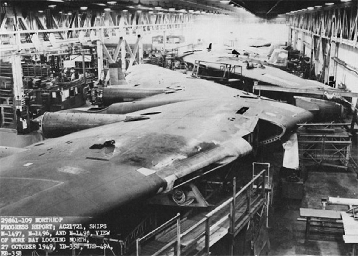 |
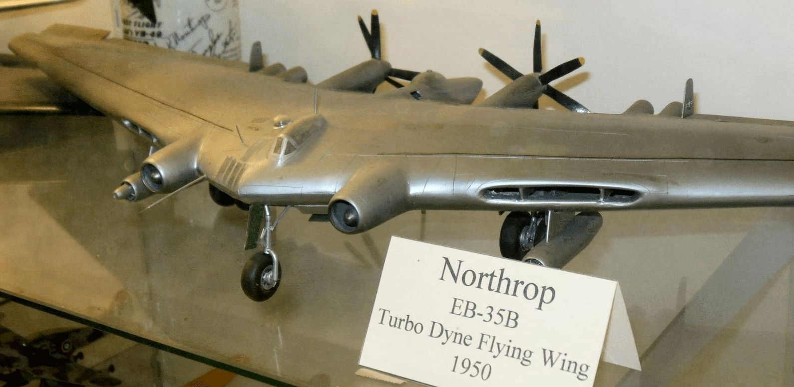 |
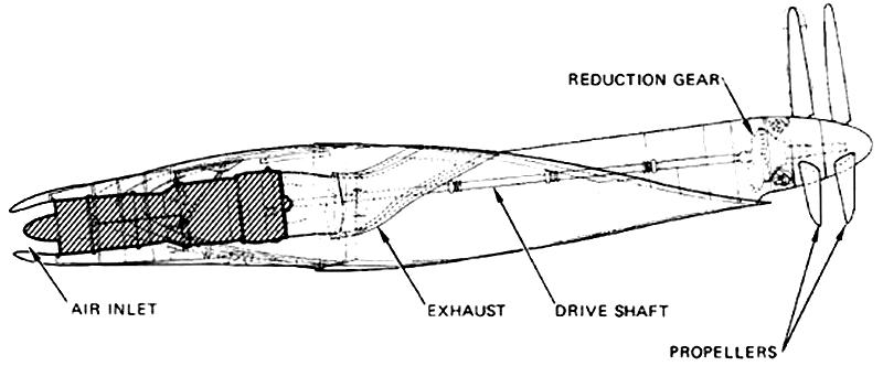 |
| EB-35B Construction | EB-35B Model (Vahe Demirjian) |
T37 in EB-35B |
14 Mar 1949. USAF Headquarters had recently authorized installation and flight test of two T37 engines in a Northrop Aircraft EB-35B airplane. This entailed 30 flight hours with one T37 installed and 30 flight hours with two T37s installed. A proposal to convert one XB-35 into a bomber was not approved. Completion was scheduled for 25 Nov 1949; delivery to AMC was 29 Sep 1950. The AMC responded on 6 Apr 1949, reporting that the USAF research and development budget precluded assumption of additional power plant development. Further, the XT37 priority was to expedite the 50-hour qualification and subsequent flight tests. Further XT37 development could be evaluated on the basis of tests then programmed. An examination of the proposed XT37 turbojet indicated it would be in the same class as the J57, J59 and J61 jet engines. With limited R&D funds, the fact the XT37 was a single rather than compound compressor engine and because its 5,235 lb weight was high, it was difficult to see how development could be sponsored.
18 Mar 1949. Col Minty cabled the Bendix Aviation Corporation Eclipse Pioneer Division requesting performance changes, mechanical difficulties, explosion hazard and expected fuel leakage in changing fuel from AN-F-32 specification to AN F-48 and AN-F-58 on XT37 control system and pump. On 24 March, the Eclipse Pioneer Division reported that no difficulties or hazards were anticipated in the fuel change.
19 Apr 1949. On 11 Apr 1949, Continental Aviation and Engineering Corporation submitted a cost proposal for four ST-175 starters and an air compressor engine unit intended for XT37 installations. Col Minty observed that the same specification No. 2025-A was for a General Electric XJ47 engine. The air compressor in Continental Dwg. No. L-1894 appeared to have been designed as ground equipment as it included its own fuel tank, battery and generator; its weight was 729 lb. By eliminating the fuel tank, battery and generator, the weight could be reduced. The Continental unit was based on the O-470-7 service-type piston engine and a General Electric Type B turbosupercharger, Part No. 4400-8456556-1 to -6. The turbosupercharger was available as Air Force stock and would be provided as GFE. The Aircraft and Missile Section Procurement Division did not have sufficient funds to purchase the starters, and suggested they be furnished instead by Turbodyne Corporation under its existing contract.
4 May 1949. Northrop Aircraft sent AMC a letter with the subject "Reduction Gears", which included Turbodyne Corporation Specification No. S104 covering a remote propeller reduction gear. Of note is that this Cross Reference and Suspense Record mentions a new contract number W33-038-ac-22281 for the first time.
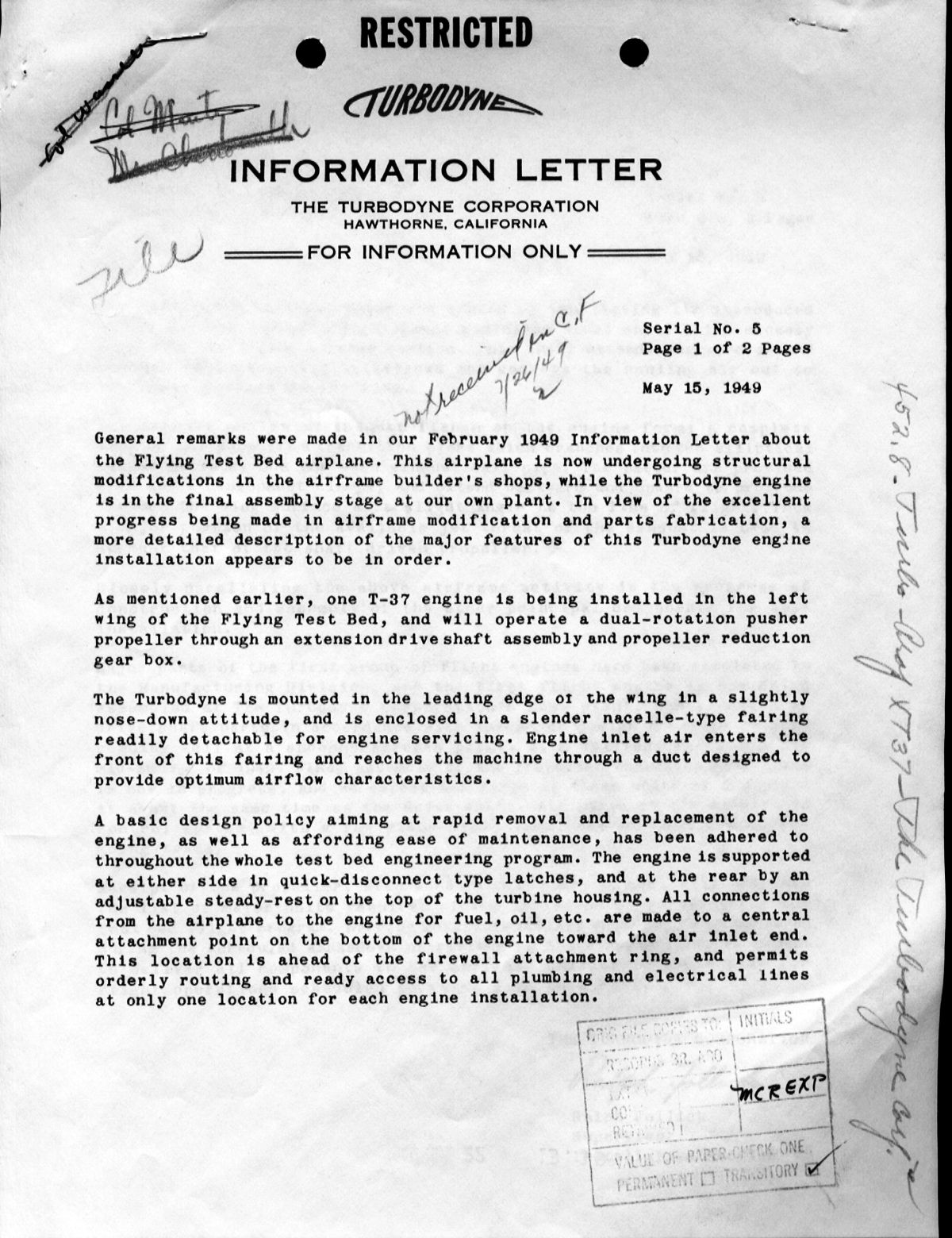 |
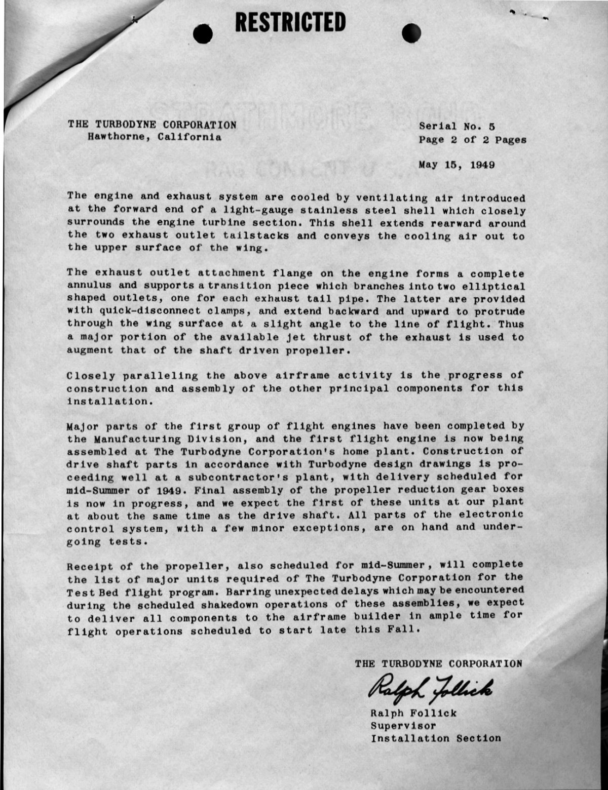 |
|
| Turbodyne Corporation Information Letter No. 5 |
||
15 May 1949. Turbodyne Corporation published Information Letter No. 5
3 Jun 1949. A Cross Reference and Suspense Record reveals that on 4 Apr 1949, the AMC received a request from Hughes Aircraft for specifications covering propeller type power plants in the 7,000 hp range. Hughes was preparing a design proposal for a large military aircraft. AMC requested that Northrop Aircraft furnish to Hughes Aircraft a specification covering the engine being developed under W33-038-ac-22281.
16 Jun 1949. Maj Howard C Goodell, AMC Engineering Field Officer at the NACA Laboratory, Langley AFB, Virginia, wrote AMC at Wright Patterson AFB, stating that Turbodyne Corporation personnel had recently visited the Langley Aeronautical Laboratory. Turbodyne Corporation's Chief Aero-Thermodynamicist F.L. Hunsaker wanted to discuss work Langley was doing on axial compressors and turbines. Turbodyne Corporation then had two Air Force contracts, one covering the development and flight test of a 10,000 shp turboprop, and the other, a study of supersonic compressor design for the AMC supersonic wind tunnel monitored by Dr. Wattendorf. Hunsaker was well informed of the compressor and turbine work at NACA Cleveland, but had never been to Langley and was impressed by the amount of work being accomplished and the character of the research equipment used.
Conferences were held with Messrs. Erwin, Boxer, Dunavant, and several technicians in the Rotating Machines Laboratory, which included six wind tunnels of various sizes used to study rotating elements and airfoil cascades. A recent improvement to the cascade tunnels included boundary layer suction applied to the side walls, which assured identical flow conditions for all cascade elements. The porous walls through which this suction is accomplished had been the object of considerable research, some of which might become applicable to aircraft wings and surfaces. Screens and perforated metal sheets were first tried; later sintered bronze. More recently, experiments had determined that certain bronze wire mesh types could be laminated and bonded by successive hammering and annealing, producing nearly any degree of porosity and an extremely smooth surface finish. [Author's note: This same technique was used with stainless-steel screen to produce the porous Rigimesh® material first used in liquid-hydrogen-fueled Pratt & Whitney RL10 and Rocketdyne J-2 rocket engine injectors.]
Mr. Hunsaker saw the mechanical potential flow field simulator that could be used to estimate cascade pressure distributions and approximate critical speeds. He appeared surprised that Langley engineers had little information on Turbodyne development, and suggested that the Dayton provide Langley a copy of a June 1948 paper by Dr. Wattandorf, "Evaluation of Turbodyne III Turbojet for Supersonic Propulsion", along with the 15 Turbodyne Corporation reports upon which the evaluation was based. This data was delivered to the NACA on 3 Oct 1949.
27 Jun 1949. Phelan had discovered that an extensive gas turbine controls program was being conducted by NACA Cleveland. Concerned about the complexity of such controls, Phelan, who had subcontracted Eclipse Pioneer to develop XT37 controls, was interested in learning if an alternate control system was available, either in the U.S. or England, and wanted to send a Turbodyne Corporation control engineer to NACA Cleveland. Phelan requested clearance for the visit. On 25 July, Col Minty replied that more information was required: a) the highest security clearance required, b) the personnel names who would attend the NACA Cleveland meeting, c) the proposed meeting date(s).
21 Jul 1949. Col George F. Smith, Engineering Division Aircraft Projects Section Chief, wrote an opinion on the use of T37 engines in cargo aircraft. He saw no advantage in using such a large engine in cargo aircraft since that would require they fly at 400 – 450 miles per hour in order to be efficient. The then-current thinking was that range was far more important than speed in cargo and troop carrier aircraft. If turboprop engine were used in cargo aircraft, Col Smith opined that 5,000 shp class engines would be more desirable; this was the power class of the Allison T40.
21 Jul 1949. Northrop Aircraft drawing Nos. 564719 and 532250, along with Northrop Aircraft report No. A-WTM-24, covering the installation of an XT37-NA-3 in a Northrop Aircraft EB-35B airplane, had been received. The report detailed velocity and local flow angle measurements in the proposed engine installation.
1 Aug 1949. Col Minty released A Brief Cost Analysis of the Turbodyne T37 Engine as of 1 August 1949
3 Aug 1949. Col Minty forwarded the XT37 cost analysis to Gen Carroll with the following comments:
1) The analysis was done by the Procurement Directorate in coordination with buyers in the Procurement Division and Engineering Division representatives.
2) In accordance with a telephone conversation between Col Minty and Gen Carroll on 3 Aug 1949, the Engineering Division recommendations concerning program continuation were included:
a) Continue the present contracts using already-obligated funds. Further funds should be withheld until the work to be done under currently-obligated funds is complete and can be evaluated.
b) No further consideration should be given to transferring XT37 development to another company.
3) The recommendations conform to the Board of General Officers decision outlined in a letter dated 4 Feb 1949, and are based on the following facts:
a) Information will be obtained on propeller/turboprop engine combination at higher subsonic speeds.
b) Experience will be obtained on turboprop engine controls.
c) This is the largest turboprop engine under development by the Navy or Air Force, and probably the largest in the world. Some valuable turbine engine experience will result from its testing. Immediate termination would lose much of the potential technical information to be gained compared with a relatively small fund recovery.
11 Oct 1949. Following a 4 Oct 1949 Staff Conference that reviewed the XT37 engine program, the Air Force Headquarters, in concurrence with the Under Secretary of the Air Force cabled Wright Field directing that:
a) No additional funds were to be allocated for the T37 50 Hour Qualification test and that installation of the T37 into the EB-35 also be terminated.
b) The Air Force should depend on Allison T38 and T40 for any turboprop engine development that was needed on short notice. The T38 was a single unit and the T40 consisted of two T38s on a common gearbox driving a contra-rotating propeller.
c) If a long-range bomber turboprop requirement materializes, the Air Force was to develop the best engine for that requirement based on gas turbine knowledge existing at that time.
AMC was to direct the contractor that the XT37 would NOT be supported beyond the funds now allocated to it and to terminate at once that portion of the B-35 conversion program applicable to the EB-35B test bed. Although the XT37 engine project was terminated, Turbodyne Corporation combustion chamber research and development, which was recognized in the field as superlative, was to be continued whenever such work advanced the U.S. gas turbine art. This work was continued under Supplement No. 1 to the XT37 engine contract, which had sufficient funds to complete the combustion chamber tests.
5 Jun 1950. Aviation Week reported that the T37 had completed test running. ["Turbodyne Completes Test Run; Northrop Aircraft's T-37." Aviation Week 52 (June 5, 1950):14] Some time in 1950, Northrop Aircraft sold its Turbodyne intellectual property to General Electric, where it lapsed into obscurity.
Conclusions and Reflections
Everyone but everyone underestimated the level of effort required to develop production gas turbines. Initially, the theory was incomplete, the material science was evolving, and there were abundant supply chain issues, testing issues and a general lack of standards. Allison won the turboprop wars and developed the T38 (Allison Model 501) into the T56 (Allison Model 501-D), which powered the Lockheed C-130, L-188, and P-3, among others. Allison had the advantage of being a long-standing engine concern with a good reputation that had teamed with General Electric to build the J33, which was based on the original Whittle engine. What a head start! Compared with Northrop Aircraft, Allison had the machine tools, factory space, engine production experience and engine testing experience that Northrop Aircraft lacked.
To Do
Numerous Turbodyne research topics remain unexplored. These include:
Find Contract No. 85598 in NARA Navy contract files.
Find Contract No. NOa(s)1321 in NARA Navy contract files.
Find drawings and really good images.
Based on prior experience, the author doubts any of the Air Force contracts can be located.
References
Vladimir H. Pavlecka - Pioneer of Aviation Revolution/
452.8 - Turboprop XT37 - The Turbodyne Corp 1940 - 1949 USNARA Record Group 342, RD3972
7 Aug 1945 Memorandum Report TSEPL-5-538-5. Conference with Northrop Aircraft Corp & Joshua Handy Iron Works Representatives Regarding Development of the Turbodyne USNARA Record Group 342, P340923
Schlaifer, Robert. Development of Aircraft Engines (Boston, Massachusetts: Harvard University, 1950)
Selected Names and Abbreviations
Berger, A.L. = MatCmd Power Plant Laboratory civilian employee
Bogert, Howard Z. (Col) = MatCmd Engineering Division Acting Chief
Botta, Rico (CDR) = BuAer Power Plant Design Section Head
Brett, George Howard (Brig Gen, Maj Gen) = Chief of the Air Corps
Carroll, Franklin O. (Maj, Brig Gen)) = Experimental Engineering Section Chief
Chenoweth, Opie = MatCmd Power Plant Laboratory civilian employee
Craigie, L.C. (Lt Col, Gen) = MatCmd Aircraft Projects Chief
Echols, Oliver P. (Lt Col, Col, Maj, Gen, Maj Gen) = MatCmd Engineering Section Chief
Gillespie, J.M. (Col) = Power Plant Laboratory Chief
Grant, L.M. (Capt) = Inspector of Naval Aircraft, El Segundo, California
Hawks, Charles R. (Maj) = MatCmd Engineering Division Liaison Section Chief
Howard, Clinton W. Maj = USAAC Experimental Engineering Section Chief
Keirn, D.J. (Capt, Col) = MatCmd PPL Chief
Kemmer, Paul H. (Col) = Engineering Section Aircraft and Physical Requirements Chief
Minty, R.J. (Col) = Power Plant Laboratory Chief
Northrop, John Knudsen (Jack) = Northrop Aircraft, Inc. Founder
Page, Edwin R. (Capt, Maj, Lt Col, Col) = MatCmd Power Plant Laboratory Chief
Phelan, Arthur J. = Northrop Aircraft, Inc. Turbodyne Technical Lead after Pavlecka
Phillips, J.F. (Col) = MatCmd Developmental Engineering Branch Chief
Prescott, Ford L. = MatCmd Power Plant Laboratory civilian employee
Spangler, S.B. (Capt, CDR) = BuAer Power Plant Design Section
Towers, John Henry (Rear Admiral) = Chief, BuAer
Wilson, R.C. (Col) = MatCmd Development Engineering Branch Chief
Wolfe, E.A. = MatCmd Power Plant Laboratory civilian employee
Send mail to
![]() with questions or comments about this web site.
with questions or comments about this web site.
![]()