The Lockheed L-188 Electra,
Allison 501 Engine and Aeroproducts Propeller
Compiled by Kimble D. McCutcheon
Published 1 Sep 2023
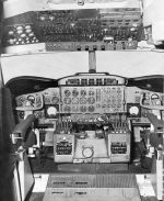
Electra Flight Deck |
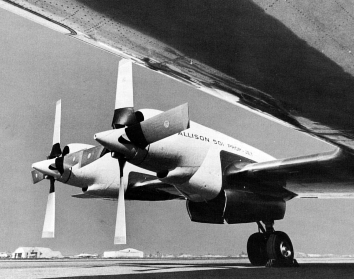
The Lockheed L-188 Electra, the first large U.S. was a turboprop airliner, first flew in 1957. It offered a uniquely high power-to-weight ratio, huge propellers and short wingspan. Most of the wingspan was covered by propwash, which, combined with the large Fowler flaps, allowed it to operate from short runways and high elevations. The Lockheed P-3 Orion submarine hunter evolved from the Electra airframe.
This artle was exerpted from Lockheed Field Service Digest, Vol. 5, Nos. 2 and 3, September through December 1958. |
Overview
The L-188 introduced several innovations:
- Turboprop power plant
- A high-output alternating-current electrical system
- Combined air cycle and vapor cycle cooling with electrical radiant heating
- Anti-icing systems using engine bleed air
- Single point refueling
- Hydraulic control surface boosters
- An integral engine starting system
The turboprop power plant had the greatest influence on L-188 design, systems and operation. Previous airliner power plants used a reciprocating engine and a suitable propeller, both of which were largely independent of one another. Reciprocating engines used separate rpm and throttle controls; turboprops combined both functions into a single control. The axial flow, single spool Allison 501 engine series together with its propeller was distinguished primarily by:
- The engine and drive shaft arrangement featured a separate propeller reduction gearbox, permitting high ram air recovery and accessory mounting on the gearbox.
- (b) A constant turbine rpm was used for takeoff, climb, cruise and descent; flight modes were entirely controlled by the propeller.
- (c) An automatic fuel trimming control that electronically refined the basic hydro-mechanical fuel metering, making a single-lever power control practical.
- (d) The power control featured a taxiing range with thrust directly proportional to lever movement, and a flight range with thrust a function of turbine inlet temperature.
- (e) Safety devices enhanced airplane handling and preserved structural integrity in case of a sudden engine failure in flight. These included negative torque system (NTS), an automatic engine safety coupling (Decoupler), a conventional low pitch stop, and a variable low pitch stop (Beta follow-up). Other safety devices included auto-feathering, the ability to feather electrically or mechanically, propeller blade pitch lock and engine fuel governor overspeed control.
Engine Development History
The Allison 501 commercial engine had a long family ancestry beginning with the military T38 and T40 turboprop engines and continuing through the T56, which was in large scale production for C-130 aircraft series and others. When the engine was first considered for airline operation in the Lockheed CL-310 (a preliminary Electra version) it was apparent that changes would be necessary. The compressor and turbine characteristics were unchanged so the constant 13,820 rpm turbine speed was retained.
The T56 military engine had a much higher propeller rotational speed of 1,106 rpm for TAKE-OFF and 1,080 rpm (97%) for the GROUND IDLE; this resulted in high ground noise levels. The T56 reduction gear ratio was 12.5:1 whereas the 501-D13 commercial engine used 13.54:1, thus giving a 1,020 takeoff propeller rpm and a 992 GROUND IDLE propeller rpm. Although this was an improvement, the GROUND IDLE noise level was still not considered satisfactory for continuous use at the passenger ramp. Allison then produced a new very low GROUND IDLE position consistent with minimum stable running. This turned out to be 10,000 turbine rpm, which became known as LOW GROUND IDLE (also Ramp Idle or Low Speed Taxi), and resulted in a 738 rpm propeller shaft speed. NORMAL GROUND IDLE (also known as High Speed Taxi or High Ground Idle), of approximately 13,450 turbine rpm, was retained for fast taxiing, engine run-up purposes, or anything requiring more thrust or more rpm.
Changes to the engine permitted kerosene or JP4 to be used as a primary fuel. Most airlines had chosen kerosene because of its lower vapor pressure and the improved safety that was believed to result. The ignition system energy was increased to provide satisfactory air starting at high altitude when using low volatility fuels such as kerosene. The engine oil specification was also changed to a commercial synthetic turboprop lubricant with an extreme pressure additive, providing longer engine overhaul life.
Engine safety devices previously developed for the military were incorporated together with some important additional features in conjunction with the Aeroproducts propeller. Several T56 changes also resulted in maintenance improvements.
Propeller Development History
 |
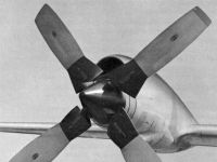 |
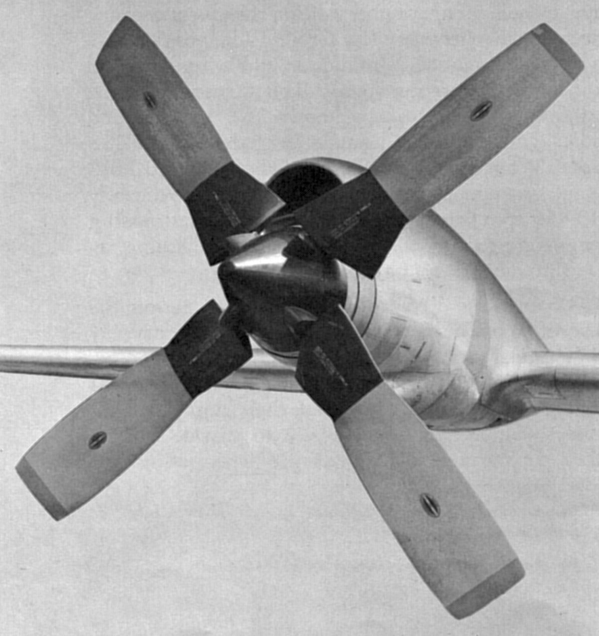
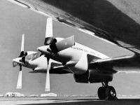
| Fig. 1. Aeroproducts Prop |
Fig. 2. Hamilton-Standard Prop |
The Aeroproducts military propeller also was adapted to commercial service, with many additional safety features and improved maintenance, such as providing a single point spinner attachment, readily removable governor and improved oil filling procedures. This propeller had a hydraulic blade angle changing mechanism that used a rifle-bore helical splined sleeve and piston arrangement, all of the propeller oil being self-contained and completely separate from the engine. Operating power for blade angle changes was generated by propeller rotation and employed higher hydraulic pressures than most other propellersw. The hole in the spinner shown in Figure 1 provided cooling air that was directed through an annular space in the propeller hub. The only electrical signals used for control purposes were for rpm synchronizing, phase synchronizing and auto-feathering; all other basic control functions such as governing, feathering, reverse pitch, negative torque signal (NTS), and taxi operation were mechanically operated from the flight station or the engine.
The spinner and blade cuffs were electrically de-iced, a feature important for avoiding ice buildup that would seriously affect engine inlet air flows. The Napier Spraymat system was used and was the first application of its kind on American aircraft. No de-icing was provided on the propeller blades themselves apart from the cuffs. The blades were forged hollow steel construction with a brazed-on camber sheet.
The 13.5-foot propeller diameter was small by reciprocating-engine propeller standards although the thrust was very high, approximately 8,000 lb for takeoff. Surprisingly enough the 18.5" wide blades had a high cruise efficiency of approximately 90%, due mainly to the blade thinness, coupled with good blade twist distribution. The cuff design and the cuff-to-spinner intersection also contributed to the high efficiency. The propeller weight complete with all control components was 1,017 lb and was thus roughly equivalent to those then used on high-powered reciprocating engines. On the other hand, the saving represented by the engine dry weight of only 1,714 lb meant a 2,731 lb total power plant weight; when compared to the Model 1049G Constellation, the total weight saving per airplane was about 6,400 lb.
An alternative propeller, the Hamilton-Standard type 54H60-47 with solid dural blades (Fig. 2), was available, and had a CAA-certified performance that was substantially similar to the Aeroproducts propeller. Cooling air entered through circumferential slots just aft of the blade cuffs and an externally applied electrical boot was used for ice protection. The hydraulic blade angle changing mechanism was similar to previous Hamilton-Standard designs.
Engine Description
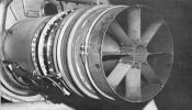
Reference to Figure 3 showing a cutaway engine view reveals that it was made up of three main assemblies:
- Propeller reduction gear and engine drive shaft.
- Engine compressor together with engine fuel, oil and ignition accessories.
- Hot section including the combustion section, turbine section and expansion area.
The engine configuration was unique and very flexible because it was available with the gearbox offset up for high wing airplanes, or offset down, as in the case of the Electra, for better layout in a low wing configuration. The propeller reduction gearing was in two stages; the first was a spur gear step down from the engine and the second a planetary gear set. Several of the engine safety devices were located in the reduction gear assembly. The forward engine drive shaft end contained the torquemeter that measured electrical phase difference signals resulting from drive shaft twisting action. Below the drive shaft connection on the gearbox rear face were mounted the engine-driven accessories, such as pneumatic starter, cabin supercharger, AC generator and tachometer generator. The reduction gear had its own dry sump oil system fed from the main engine oil tank.
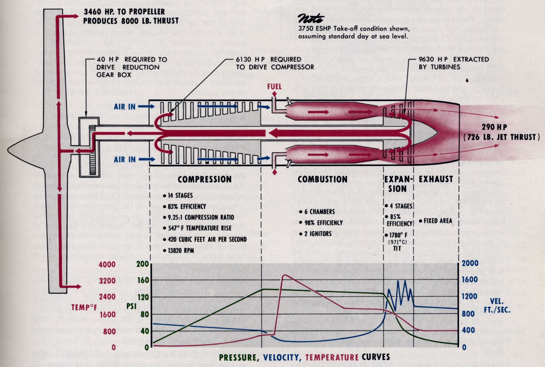
Moving back toward the compressor air inlet, the inlet struts and guide vanes were hollow and were anti-iced with air bled from the compressor. The torquemeter shroud and drive shaft housing were similarly protected from icing. The compressor had 14 stages and operated at a 9.25: 1 compression ratio . Annular bleed ports together with acceleration bleed valves were provided at the 5th and 10thcompressor stages for unloading in the surge range, which was roughly 7,000 to 12,500 rpm. The acceleration bleed valves were an alternative method to the use of variable angle inlet vanes for compressor surge control purposes, and they were open at the 10,000 rpm LOW GROUND IDLE position. At the 14thstage, bleed ports supplied hot air for airframe anti-icing and other purposes. Below the compressor case was an engine accessory drive section carrying the fuel control, fuel pumps, filters, oil pump, speed sensitive control, etc. Aft of this was the coordinator control that was mechanically linked to the power lever in the cockpit.
Air from the compressor entered the diffuser section and was distributed equally to six canannular burner cans in the combustion section. A large proportion of the air flowed outside of the burner cans as secondary air and entered through burner can slots to cool the cans and control the flame pattern. Each burner can was fed by a fuel nozzle and two of the cans had ignitors, the flame being carried during starting to the other four cans by cross-over tubes. Moving aft, the hot gases from the burner cans combined in an annular area to feed through stator vanes into the four stage turbine assembly. It was at this position that the 18 dual thermocouples measuring turbine inlet temperature (TIT) were mounted. Turbine inlet temperature measurement provides a much more accurate value than measuring the outlet, or exhaust gas temperature, as in most other engines.
A relatively small amount of the energy from the turbine final stage left the tailpipe in the form of jet thrust. The 3,750 Equivalent Shaft Horse Power (ESHP) was made up of 3,460 Shaft Horse Power (SHP) plus 726 lb jet thrust. The jet thrust was factored by 2.5 to approximate ESHP so that 290 hp was added to the propeller shaft power to obtain the takeoff power rating. The reason for using four turbine stages, unlike a turbojet engine that normally uses fewer, was that the maximum energy was extracted as shaft power for the propeller, rather than in the form of jet thrust. This is illustrated in Figure 4, which shows typical power, temperature, velocity and pressure relationships. In general terms some 10% of the cruise total thrust comes from the jet pipe.
Engine starting was accomplished by a pneumatic starter, a small high-speed air turbine capable of very high power output. It was necessary to extend the cranking range of the starter to an engine speed of 8,000 rpm to avoid "hot starts" and to ensure positive engine acceleration. Several things happened automatically in the starting sequence, including turning on fuel and ignition, controlling fuel pump output and operating the acceleration bleed valves. Most of these functions were controlled by the speed sensitive control unit. The ignitor plugs operated only during the starting sequence and cut off at stabilized speed, engine combustion being continuous thereafter.
The engines could also be air started by windmilling after an in-flight engine shutdown. A propeller brake was provided to eliminate windmilling after feathering in flight and also to prevent engine rotation in a strong wind on the ground. The brake also assisted in slowing down the engines at shutdown. The brake was mounted in the propeller reduction gearbox accessory section just behind the starter pad and was operated automatically by engine oil pressure. The propeller could be pulled by hand against the brake if necessary for maintenance purposes, but in one direction only since it prevented reverse rotation.
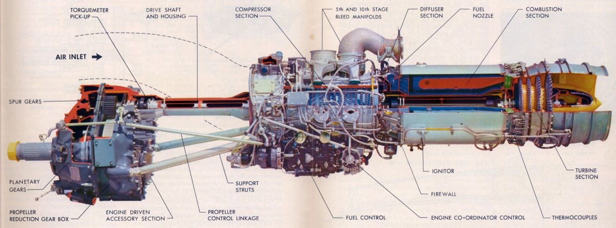 |
| Fig. 3. Allison 501 Cutaway |
Automatic Fuel Trimming Control
Turbine inlet temperature (TIT) control was the key to the single-power-lever engine operational simplicity. The engine had a basic hydro-mechanical fuel control, which was similar to many other turbine engines. However, the exact fuel flow adjustment was accomplished in a unique way. The fuel control actually fed 120% of the amount required to operate the engine and a fuel trimming device consisting of an electronically-controlled temperature datum valve (TD Valve) either "put" or "took" a portion of the excess fuel delivered to it. This TD Valve maintained the selected TIT or limited it to a 971°C maximum value. It was a temperature-density variation control that bypassed fuel based on signals from the electronic temperature datum control amplifier (TD Amplifier). This amplifier was a comparator that measured the TIT thermocouple outputs versus power lever angle provided by a potentiometer in the Coordinator, and then sent an output signal to the TD valve to trim the fuel flow accordingly. The fuel was passed through a flow divider that equalized the flow to the six fuel nozzles. The TD System was a fuel heat-content sensitive device and was capable of adjusting itself to a range of different fuels from gasoline through JP4 to kerosene.
If a TD System electrical failure occurred, the TD Valve would return to the NULL position and the crew would revert to manual control of that particular engine by observing the TIT gauges and manipulating the power lever. A feature was included that permitted "locking in" the last "put" or "take" adjustment for the engine and thus shutting off the TD system action, while still providing fairly accurate hydro-mechanical fuel control. This device was intended for landing purposes to provide uniform power lever angle versus thrust conditions for all four engines.
The Power Lever
 |
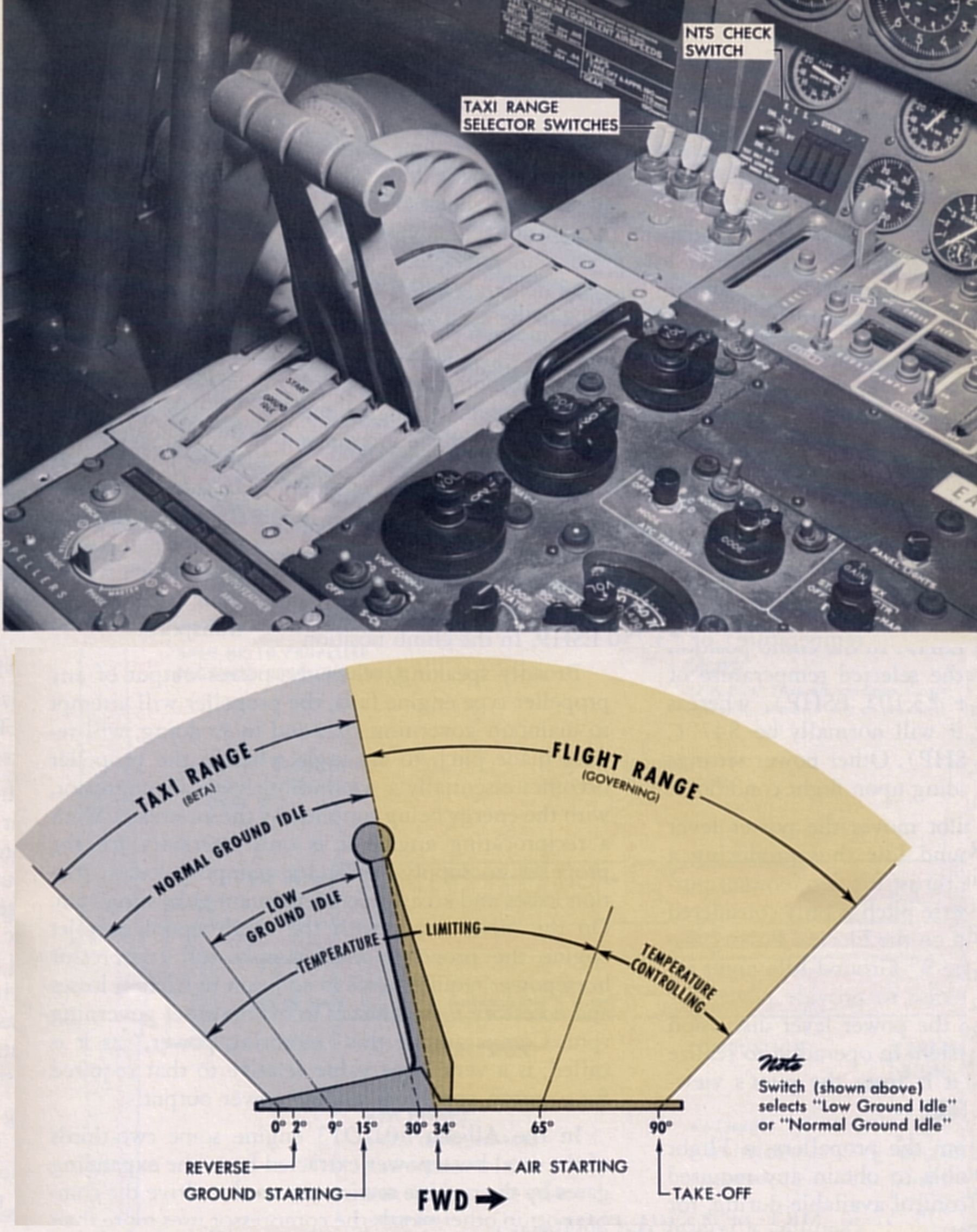
| Fig. 4. The Power Lever |
The power lever (so called because it does really control power in the total sense and not merely open a throttle valve) had two basic ranges in its 90° quadrant (see Fig. 4).
- (a) TAXI RANGE or "Beta Range" (Beta comes from the aerodynamic term for blade angle signified by the Greek letter β) was used for all ground conditions and was aft of the 34° detent or FLIGHT IDLE position. In this range, blade angle control was directly related to the power lever position with the engine rpm at approximately 13,450 or below. Thrust was proportional to blade angle.
- (b) FLIGHT RANGE or "Governing Range" was used for all flight conditions and was forward of the 34° travel position. In this range engine speed was governed to 13,820 rpm by the propeller. Thrust was proportional to turbine inlet temperature (TIT).
The power lever had to be lifted positively when pulling back from the FLIGHT RANGE to permit entering the TAXI RANGE or Beta Range and a device was included to prevent accidental entry while the airplane was in flight. This power lever lift motion was similar to the lift-to-reverse action provided on several then-contemporary reciprocating engine transports for propeller reversing. However, the Electra required no separate lock release action apart from lifting the power levers since the safety device was actuated by a landing gear scissors switch. In case of malfunction the device can be over-ridden by the use of additional force on the power levers and was thus fail-safe. The connection between the propeller and the power lever was mechanical only and did not rely upon electrical functions.
It should be appreciated that the detent or "gate" was at the FLIGHT IDLE (34°) position in this prop-jet engine control system, unlike a reciprocating engine/propeller control that was normally at the point where the throttle levers enter reverse pitch. The reason for this important difference was principally concerned with the existence of jet thrust from the tail pipe. Whereas reciprocating engine/propeller controls modulate down to low thrust (fine pitch approach conditions) the next throttle movement was directly into reverse pitch by withdrawal of the low pitch propeller blade stop. On the other hand, while the FLIGHT IDLE position in the prop-jet corresponds roughly to the low pitch stop position in the reciprocating engine, a fairly large component of forward thrust was added by the jet pipe. Consequently it would be difficult to slow down and control the airplane on the landing run if the next step was reverse pitch. For this reason a blade angle control was developed that permitted modulation below the FLIGHT IDLE position and appropriately named the "Beta control" range. Therefore, when the jet thrust made lower blade angles necessary on the ground for the prop-jet the blades were actually in reverse to a limited extent for static ground running purposes. It follows that there was no "gate" for reverse and further retarding of the power levers provides full reverse, if it should be required.
Figure 4 shows that REVERSE begins at the 2° engine power lever position while maximum reverse was at 0°. A small detent was provided at 9° for GROUND IDLE. Engine starting was accomplished at 15° since this corresponded to the minimum torque requirement condition for the propeller and engine. LOW GROUND IDLE at approximately 10,000 rpm was obtained by putting a TAXI RANGE selector switch in the LOW position. At this point the total thrust from the propeller was close to zero, causing the customary wind blast around the passenger ramp was noticeably absent. Sufficient thrust was available, however, for taxiing on four engines at this setting by advancing the power lever as required from 9° up to 30°. If more thrust was required the selector switch could be moved to the "NORMAL" ("High Ground Idle") position providing approximately 13,150 rpm, the fuel demands being satisfied automatically. This switch can he seen in the Figure 4 detail view.
Advancing the power lever through the 34° detent towards the TAKE-OFF position moves it out of the temperature limiting range wherein the engine was protected from overheating by a limiting device, into the temperature controlling range commencing at 65°; the selected TIT value was controlled automatically by the TD System. At the 90° or TAKE-OFF position the TIT was automatically controlled at the maximum value of 971° C (100% maximum rated temperature, MRT) or 3,750 ESHP. In the climb position the TIT remained at the selected temperature of 895 °C (94% MRT or 3,105 ESHP) , whereas in the cruising position it was normally be 847°C (90% MRT or 2,700 ESHP). Other power settings were used depending upon flight conditions.
On touch down the pilot moved the power lever from FLIGHT IDLE to GROUND IDLE thus producing a large amount of negative thrust for deceleration purposes. The use of full reverse pitch was only considered in an emergency condition on the Electra. Pulling the power lever back from the 9° GROUND IDLE point increases fuel flow, in this case to provide power for reverse pitch, To sum up the power lever discussion one only had to see the system in operation to realize how delightfully simple it was from the pilot's viewpoint ‑ just watch the TIT!
The propeller drag available in FLIGHT IDLE made it easily possible to obtain any required descent rate and the control available during, for example, a typical ILS approach was almost uncanny. To the pilot, the airplane acceleration or deceleration appears to be directly linked to the power levers themselves. The absence of a need to clear the engine prior to takeoff was another differing prop-jet characteristic and wheel brake and tire life was much improved because of the incremental propeller thrust control available during taxiing.
Safety Devices
 |
| Fig. 5. Allison 501 Power Relationships |
Gas turbine engines have characteristics that are markedly different from reciprocating engine-propeller combinations. Early in 1953, while developing the prototype YC-130 military transport with the YT56 engine, Lockheed made extensive safety investigations. Using this research together with data derived from the Pratt & Whitney T31 engines installed on the YC-121F and the R7V-2 (U.S. Air Force and Navy turboprop L-1019 Constellation versions) developed concepts for protective devices. The test work included an extensive full scale T56 engine program in the power plant wind tunnel at Ames Aeronautical Laboratory as well as flight testing in a Constellation flying test bed airplane. The basic premise was that a turbine powered airplane must have an in-flight safety level that was at least equal to, or preferably better than, that of equivalent reciprocating-engine transports.
When the power output of any propeller type engine fails, the propeller will attempt to maintain governing rpm and in so doing, will reduce blade pitch to an angle wherein the propeller becomes essentially a windmill driving a compressor, with the energy being supplied by the airstream. With a reciprocating engine it was only necessary for the propeller to supply power for pumping losses, friction losses and accessories to maintain governing rpm. On the other hand, with the single spool prop-jet engine the propeller must supply full compressor horsepower requirements in addition to friction losses and accessory requirements to maintain set governing rpm. Comparatively this "motoring power," as it was called, was a very large value relative to that required for a piston engine of similar power output.
In the Allison 501-D13 engine some two-thirds of the total horsepower extracted from the expanding gases by the turbine section were used to drive the compressor; in other words the compressor used more than 6,000 shaft horsepower. Refer again to Figure 5 that shows the horsepower relationship graphically. From the previous paragraph it was apparent that the blade angle depended upon the negative torque load required to motor the engine in the event of a sudden engine failure in flight. Study of the horsepower relationship diagram shows that such a failure could result in the absorption of enormous power from the air stream if protective devices were not included.
In general, two types of engine failure prescribe the maximum and minimum boundaries of necessary protection. The most simple and probable case would be flame out due to fuel flow failure. In this case, the engine was undamaged the turbine wheels would continue to supply some useful energy to the compressor because the compressor discharge air was still expanding through the turbine blading, even though the mixture was not combustible . The negative horsepower under this condition, in other words the power that could be absorbed from the air stream by the propeller at its governing speed of 1,020 rpm, would be about 1,500 SHP in order to motor an unprotected engine under typical conditions of about 300 knots at sea level. The most severe case resulted from turbine blade failure and in such a case the propeller, if in fairly low pitch, could absorb the full 6,000-plus shaft horsepower required to drive the compressor if no torque limiting devices were installed. Typical drag loads that could he caused by, for example, a failure of an unprotected outboard engine at the 300 knot sea level case would be around 1,000 lb in the fuel flow failure example, whereas a complete turbine failure could approximate 15,000 lb. Adding the effect of the thrust from the remaining live engines would increase the total asymmetric drag values to some 7,500 lb and 15,500 lb respectively. Several devices were built into both engine and propeller to completely protect against these occurrences and in addition structural strength was provided in the vertical tail surfaces to take care of critical yawing load coupled with forces arising from corrective action by the pilot.
Negative Torque System (NTS)
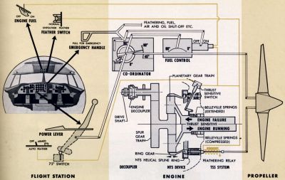 |
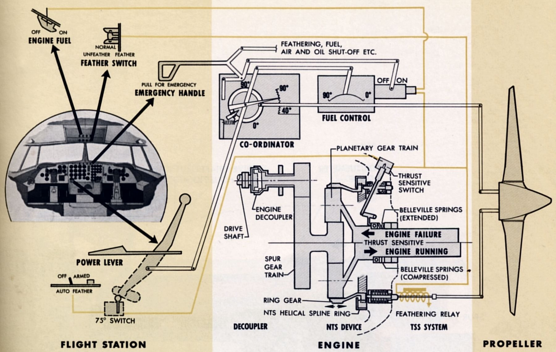
| Fig. 6. Engine/Propeller Control and Safety Devices |
The propeller was prevented from absorbing large values of negative torque in the event of a fuel flow or turbine failure by a negative torque signal system that was incorporated in the reduction gearbox. This system used the axial output movement from a helical spline and coil spring assembly caused by the unloading effect of the propeller upon the planetary ring gear. It actuated the propeller increase-pitch function to absorb more engine power (See detail in Fig. 6). The system permitted a small negative-torque value to provide a useful amount of propeller drag at FLIGHT IDLE that would he necessary, for example, during approach conditions. This device functioned at approximately minus 375 horsepower and the crew would feel it working by a cyclic thrust variation if the engine power did not immediately increase. Torquemeter fluctuations would also tell them of the engine condition. NTS operation also occurred under conditions not associated with failures, e.g. during a steep approach or when the propeller encountered air gust loads. The NTS system was operative over the range of power lever position from 21° to 90° (refer again to Fig. 4). The NTS System could be checked prior to takeoff to ensure proper operation.
Engine Decoupler
This device is, in effect, a mechanical fuse that backed up the NTS if it failed to work at about minus 375 horsepower; when the negative horsepower magnitude reached around minus 1,500. The decoupler worked in a fashion similar to the NTS using a helical spline operating against Belleville spring washers as a negative torque sensing device. When decoupling took place, the two halves of the coupling separated and the engine power section was disconnected from the reduction gear box. After the failed engine had decoupled the propeller would continue to windmill at governing rpm because of its independent hydraulic oil system, but at a relatively high blade angle and with low drag. Such a double failure would be extremely rare, but the airframe structure was designed to withstand such a critical combination., The decoupler re-engaged in flight once the negative torque was removed but had to be inspected and possibly replaced before the next flight. The decoupler, illustrated schematically in Figure 6, was mounted within the reduction gear box at the drive shaft forward end.
Variable Hydraulic Low-Pitch Stop
The "Beta follow-up" (the more usual name for this device) minimized asymmetric thrust should engine failure or propeller malfunction occur. It was a variable-position low pitch stop that limited improper propeller blade travel much more suitably than a fixed mechanical low pitch stop could. For example, if fuel flow failed during take off, primary protection was provided by the "Beta follow-up," while at high speed cruise conditions the protection was normally provided by the NTS system. Its operation was typically as follows: If the NTS failed to signal for increased pitch the propeller governor would normally tend to decrease the blade angle toward the low pitch stop at 20°. With this device, however, the blades were stopped at, for example, about 31° for the take oil power condition and consequently the windmilling drag would be greatly reduced. The hydraulic low pitch stop position varied from 20° blade angle at 68° power lever position to 30° blade angle at the 90° position. Between the 68° and 34° FLIGHT IDLE power lever position the "Beta follow-up'' acted as a fixed hydraulic low pitch stop ensuring a minimum 20° blade angle. This device would operate before the engine decoupler was called upon to operate. The "Beta follow-up" was contained within the propeller but is not illustrated in this article.
Mechanical Low Pitch Stop
This low pitch stop (18.25°) was a back-up device for the "Beta follow-up" and corresponded to the conventional low pitch stop used on reciprocating engine propellers. This served as a positive barrier to prevent the blade from going into the negative range ‑ such as in flight reversing – unless scheduled to do so. The stop was so arranged, however, so that it could be overpowered from the flight station if necessary to ensure that the Beta range could be obtained on the ground.
Auto Feathering System
An automatic feathering system allowed maximum airplane gross weight under limiting airport performance conditions. It was actuated by a separate thrust sensitive signal (TSS) device that was independent of the other safety devices when the propeller delivered less than 500 lb of positive thrust. The other previously described devices required negative thrust to actuate them. The TSS was operated by a fore-and-aft propeller shaft movement that had a total travel of 0.10" against Belleville springs. Details of the system can he seen in Figure 6. It was armed only during the TAKE-OFF range by a switch operated from the power lever at the 75° position, in addition to a manual switch operated by the pilot.
Overspeed Limiting Mechanical Pitch Lock
To protect against propeller governor failure, a device was built into the propeller that mechanically locked the blade pitch at an engine overspeed of 14,300 rpm (3.5% above normal). The propeller could be feathered normally, however, even when the pitch lock was engaged.
Overspeed Fuel Control Governor
The engine fuel control contained a flyball overspeed governor operating at 14,450 rpm (4.5% above normal). This condition could only occur in flight when a double failure of the propeller governor and/or mechanical drive between the engine and the reduction gear box. This overspeed governor was also known as the "topping governor."
Other Safety Features
The power plant included normal and emergency feathering systems. The Electra also featured by two separate propeller feathering systems ‑ one electrical, and the other mechanical. A minimum feathering oil reserve ensured feathering capability if substantial propeller oil loss occurred. One safety device concerning the power plant deserves special mention here. A handle was provided for each engine that engaged several simultaneous emergency shutdown functions, most mechanically actuated. A single movement the selected emergency handle shut off fuel at the engine, feathered the propeller, operated the fuel tank emergency shut off valve, shut off the generator cooling air, and so on, combining eight functions in all. Original development of this system came from the C-130 transport. Figure 6 illustrates this together with most of the other safety devices previously described.
Summarizing the power plant safety features discussion, it should be understood that the airframe had been designed so that it had adequate strength to survive the most improbable compounding of failures of the safety devices described under the most unfavorable operating conditions.
Power Plant Installation
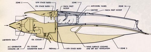 |
| Fig. 7. Inboard Engine Inatallation |
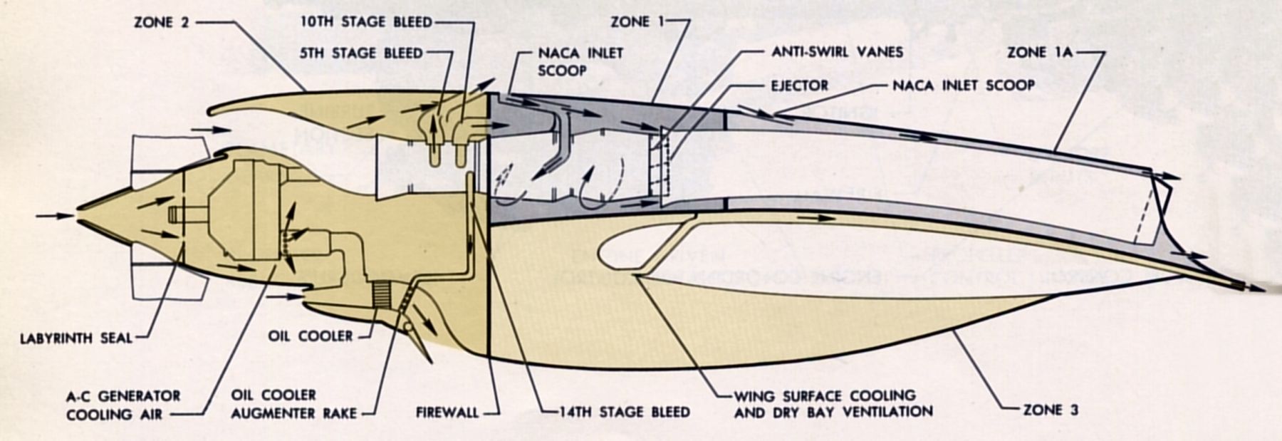
Engine and propeller review would not be complete without briefly considering how they were installed in the airplane. The choice of the low wing airplane configuration dictated, for propeller tip clearance and landing gear installation reasons, that the engine centerline be higher than the wing. The reduction gear box on such an installation must necessarily be offset downwards to obtain, as nearly as possible, alignment of the propeller thrust line with the wing chord line. This configuration in turn, established the over-wing arrangement of the exhaust tailpipe as well as the high air intake position (see Figure 7). When the adverse drag of short tailpipes was considered, it was decided that they should extend to the wing trailing edge.
With reciprocating engine intake design practice, ram pressure recovery values of 75 - 85% were typical; the Electra was 98% in order to meet speed and range requirements. Careful design achieved this together with a good ram pressure ratio, resulting in good overall engine inlet/outlet efficiency. In practice the design objectives were exceeded and more than 100% total pressure ratio was available at cruise due to the propeller pumping action and exhaust ejector negative pressure at the outlet. In practical terms this amounted to an increase in available power of approximately 3% during cruise and for 5% for takeoff.
 |
 |
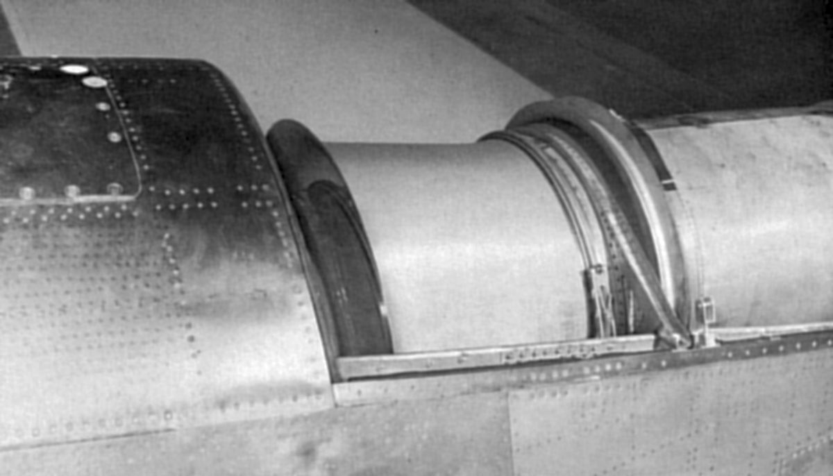
| Fig. 8. Exhaust Ejector Bellmouth, Anti-Swirl Vanes |
The exhaust ejector, illustrated at the top of Figure 7, consisted of a bell-mouthed section that induced air into the tailpipe; forward of this were anti-swirl vanes that straightened the engine exhaust gas thus increasing the axial component of jet thrust. In order to provide an adequate air source for the ejector when running at 10,000 rpm the 10thstage bleed air was directed into the tailpipe zone. The 5thstage bleed air was separately dumped directly overboard. Cooling airflow was provided around the tailpipe, introduced through an NACA flush inlet atop the tailpipe forward door. Turbine zone cooling air was provided from a similar flush inlet together with flow distribution ducts. This inlet also served as the exhaust ejector secondary air source. The wing upper surface was kept cool by a separate ram air system with inlets in the wing lower surface just outboard of each nacelle. The same air source was used to vent the wing dry bays in the inboard nacelles and, in the outboards, to cool the engine air starter bottle system (when installed).
The propeller spinner contour, a modified conical form, was chosen because of its compatibility with the critical air intake flow requirements, and a labyrinth seal was used to prevent excessive propeller cooling air spillage between the fixed and rotating sections that would upset the boundary layer flow. Cooling air from the propeller passed into the accessory zone under normal flight conditions and when propeller feathering occurred, was mechanically shut off automatically. The boundary layer lip on the engine air intake was designed for optimum ram recovery even at the higher angles of attack common to takeoff and initial climb. Both the intake lip, and the top of the intake duct were anti-iced by 14th-stage air bleed. The 19" tailpipe diameter was chosen after a careful study to determine the optimum engine arrangement versus the lowest drag penalty.
 |
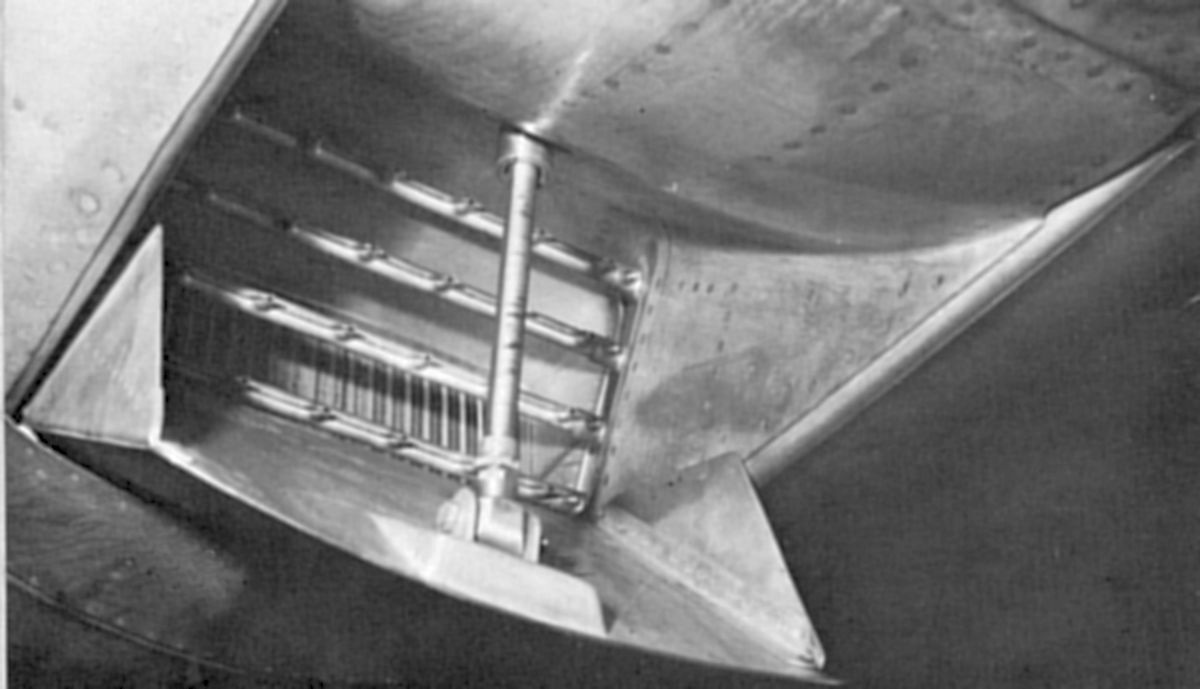
Fig. 9. Oil Cooler
Airflow Inducer Rake |
Several miscellaneous points of interest involved the power plant installation. For example, the engine ground running condition required a propeller blade angle that was negative at the propeller tips in order to offset the static jet thrust. This resulted in very low airflow over the oil cooler so an airflow inducer rake, or augmenter, fitted on the aft side, used bleed air exhausted through nozzles to draw cooling air over the matrix, thus providing adequate cooling irrespective of the airplane's orientation with respect to the wind. A detail view of this feature is shown in Figure 9. Another interesting point was the use of an oil-to-oil accessory heat exchanger in the engine oil cooler outlet line for cooling the cabin supercharger oil. This provided accessory cooling without the complexity and drag penalty associated with a separate cooler.
The most notable power plant installation aspect was that for the first time the engine provides more power when installed than when running on the manufacturer's dynamometer. The attention paid to propeller and induction system design details and exhaust system configuration paid dividends with the power available to more than meet performance guarantees.