Aircraft Magnetos
Compiled by Kimble D. McCutcheon
Published 17 Jan 2015; Revised 18 Apr 2022
|
Magnetos comprises stand-alone engine ignition systems capable of generating the energy necessary to jump spark plug gaps and delivering it to the correct engine cylinder with precise timing. Magnetos accomplish this by subjecting coils of wire to varying magnetic fields, thereby generating a low-tension (low-voltage) electrical current. This low-tension current is then amplified to high-tension (high-voltage) current capable of jumping a spark plug gap by an electrical transformer. |
Introduction
Smaller magnetos include all these elements within the same housing. As engines designs included more cylinders, it became convenient to separate the magneto and distributor functions into separate housings.
The two broad classes of magnetos, high-tension and low-tension, designate whether the low-tension current generated by the magneto is converted to high-tension within the magneto (high-tension) or outside the magneto (low-tension). We shall use very early aircraft magnetos, many of which were borrowed from automotive applications, to illustrate high-tension magnetos. Low-tension magnetos, which found favor in aircraft operating at high altitudes, simply moved the coils that transformed low primary voltage to high secondary voltage, outside the magneto.
Safety and performance considerations led aircraft engine designers to specify dual ignition systems. This requirement was first met with two single magnetos. Later, dual magnetos with two coils, two condensers, and two breakers but a single rotating magnet and drive, found wide use. These were lighter and used fewer parts, both in the magneto and the engine, than two single magnetos.
High-Tension Magneto Construction
Although all high-tension magnetos have similar operating principles, their construction differs depending on how the coil is subjected to magnetic field variations. Magnetos always include a rotating member, which may be an armature, inductor, or magnet. Four broad construction categories emerged, which are described below.
Revolving-armature or shuttle magnetos rotate a coil of wire within a magnetic field generated by a horseshoe magnet. Some of the earliest magnetos were of the revolving-armature type, but difficulties with routing high-tension current out of the revolving armature led to a rise in popularity of other types with stationary coils.
Sleeve-inductor magnetos feature an iron sleeve rotating within a magnetic field generated by a horseshoe magnet. The sleeve conducts the magnetic field to a stationary coil, thereby generating the varying magnetic field. This type of magneto is rare.
Polar-inductor magnetos feature iron poles rotating within a magnetic field generated by a horseshoe magnet. The bar conducts the magnetic field to a stationary coil, thereby generating the varying magnetic field. This type of magneto is more common
Rotating-magnet magnetos feature bar magnets that rotate within fixed poles that conduct magnetism to a fixed coil. These are smaller and lighter than magnetos employing horseshoe magnets, and have generally displaced all other types over time.
Revolving-Armature Magnetos
A magnetic field is produced by permanent horseshoe magnets, called field magnets. A coil is wound onto an iron drum that rotates in the magnetic field. The coil/iron drum assembly is called an armature. Current is collected via stationary carbon brushes that bear against the commutator and routed outside the armature. A condenser, mounted to the armature, helps reduce arcing. The breaker opens when the primary current is at maximum, thereby inducing the high voltage in the secondary winding.
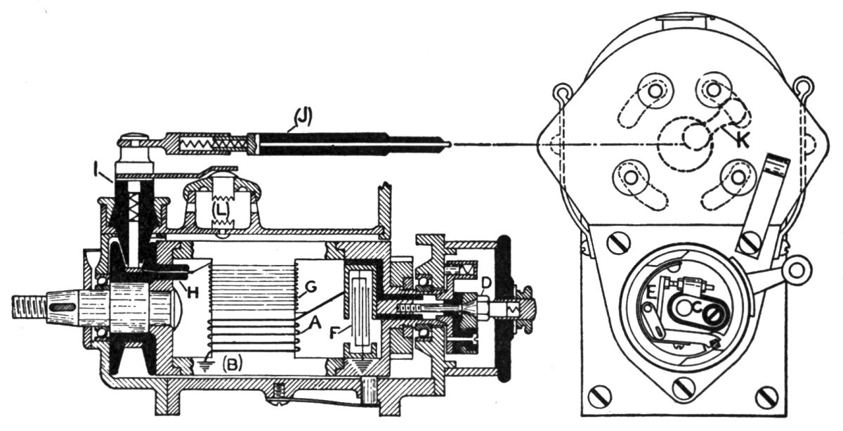
In the magneto circuits shown in Figure RA-1, one end of the primary winding A is grounded to the soft iron core B and the other end is connected to the contact blocks C by the fastening screw D, which passes through and is insulated from the breaker base. The contact block C carries the adjustable contact point, which is also insulated from the breaker base and is electrically connected to the armature core through the ground. The breaker lever E carries the stationary contact point which is in contact with the adjustable point in block C. The breaker lever, being electrically connected to the armature core or ground, is thus connected to one end of the primary winding. When the contact points are closed, the primary circuit is completed.
The condenser F in rotating armature magnetos is built into the armature, one end being connected to the lead screw and the other grounded, thus placing the condenser in parallel with the contact points. The condenser housing serves as one of the one of the non-magnetic end plates of the armature. The secondary winding G consists of a large number of turns of very fine wire directly over the primary winding, but heavily insulated from it as well as from the frame or ground. One end of the secondary winding is connected to the primary winding and is directly grounded through it; the other end is connected to the collector ring H. From this point the secondary current is conducted to the collector brush and holder I, through the high-tension pencil J to the distributor and makes contacts by the distributor brush K to the segments on the distributor, which are connected by wires to the spark-plugs. At this point it is forced to jump across the spark-plug gap to ground, returning through the engine to the grounded side of the primary winding and then through the primary winding back to the point where the secondary is connected to it, thus completing the secondary circuit.
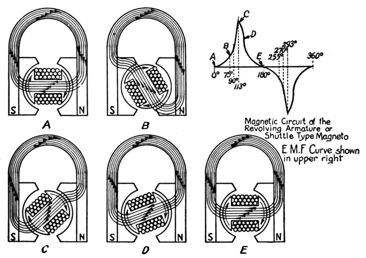
When the contacts are closed and the armature is revolved, cutting across the magnetic lines of force produced by the permanent magnets, there is induced an electro-motive force (emf) that causes current to flow in the primary winding which builds up a strong magnetic field about the armature windings. When the armature to the point where maximum voltage will be induced in the primary, the beaker contacts are opened by the fiber block of the breaker lever traveling over the cam in the breaker housing. This occurs just as the magnetism reverses in the core of the armature. Due to this rapid flux variation across the secondary winding, a high induced emf is produced, which follows in the secondary circuit. In the ordinary magneto of the revolving-armature type there are two alternations per revolution of the armature. The travel of the magnetic lines of force at the various armature positions is shown in Figure RA-2.
A safety gap which is located in parallel with the secondary circuit. When secondary resistance becomes very high, such as when one of the spark plug wires is disconnected, the safety gap (Fig. RA-1 L), whose gap is much wider than a spark-plug gap, conducts the current to ground. This prevents breakdown of the highly-insulated magneto components.
 |
 |
 |
 |
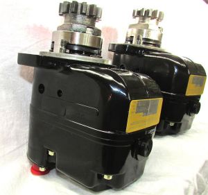
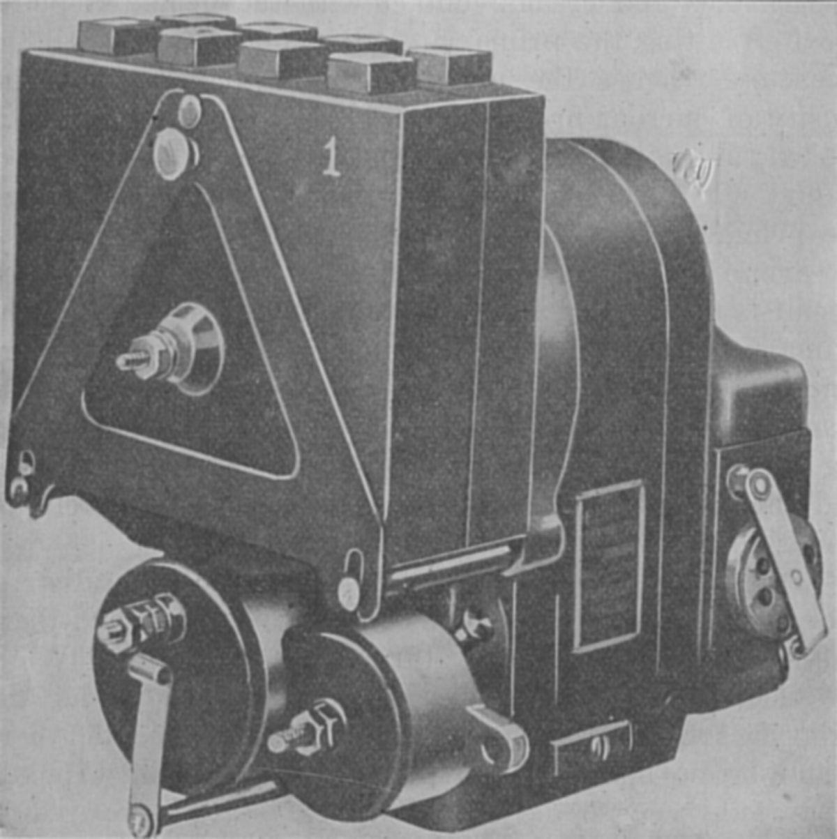
| Fig. RA-1. Rotating Armature Magneto Schematic | Fig. RA-2. Magnetic Field Flow | Berling Rotating Armature Magneto | Berling Magneto Repair Video |
Polar Inductor Magnetos
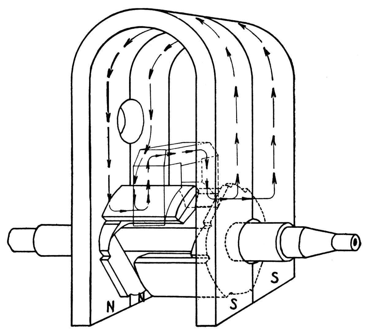
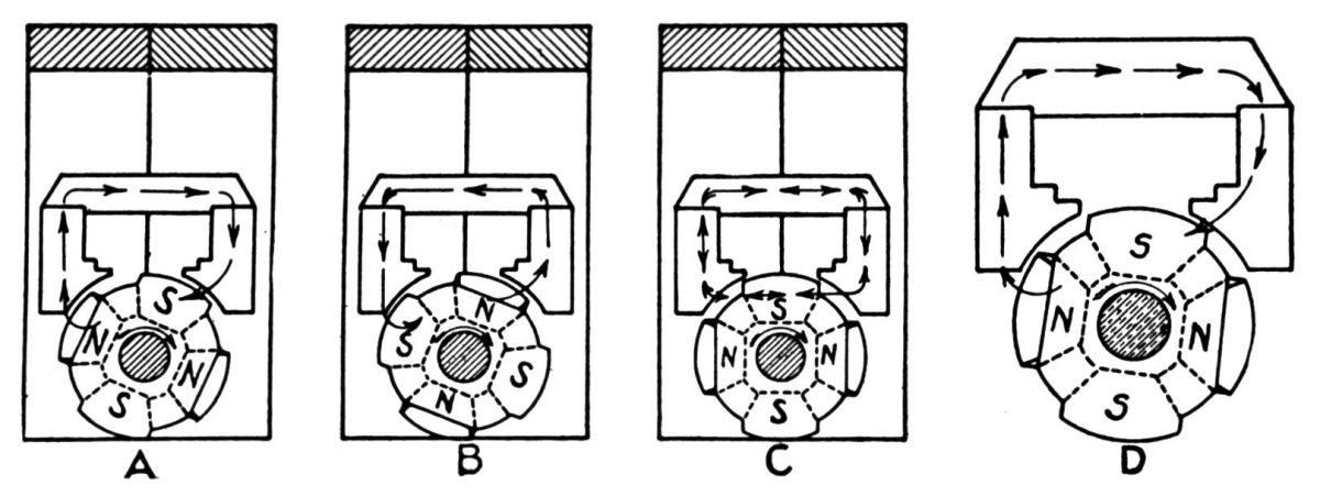
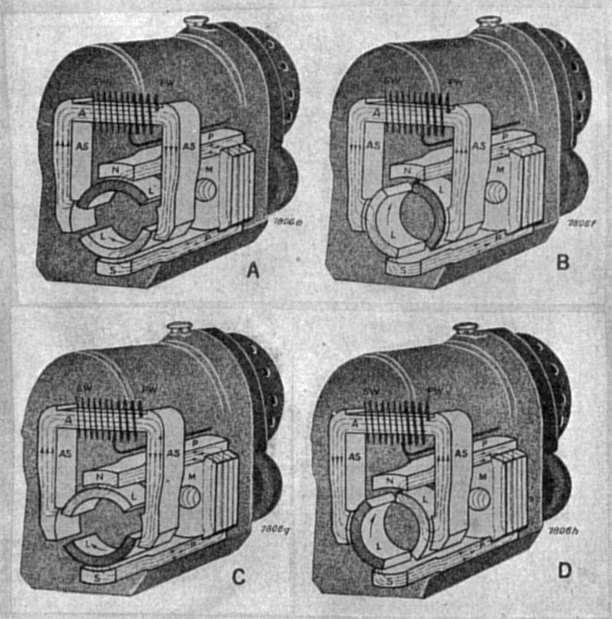
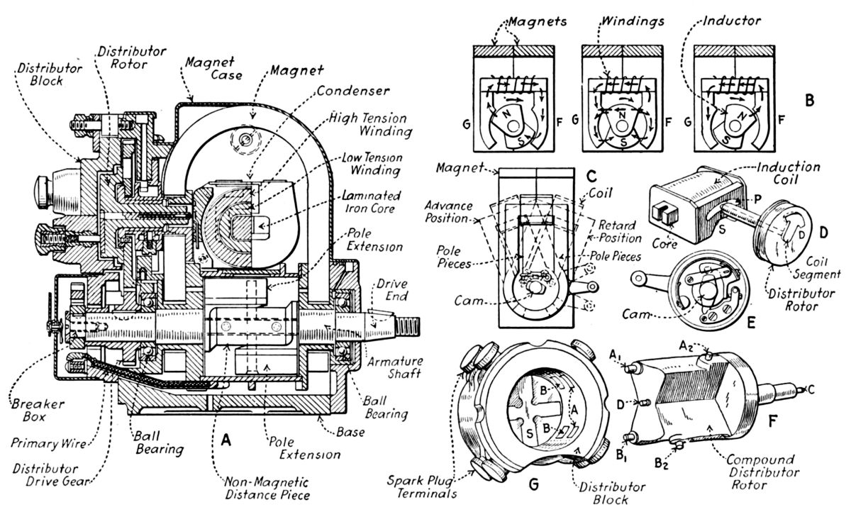
The inductor magneto replaces the rotating armature with a fixed coil that is subjected to a varying magnetic field generated by field magnets and switched by rotating inductors. The rotating inductor consists of magnetic conductors (inductors) that are separated by a bronze center piece. The ends of the inductors operate in close proximity to stationary coil and field magnet pole pieces. Figure In-1 illustrates the magnetic circuits of a four-pole inductor magneto. Note that in this inductor arrangement, magnetic polarity through the coil's laminated core reverses four times during each rotor revolution (Fig. In-2). Figure In-3 is a schematic of the inductor magneto electrical circuits..
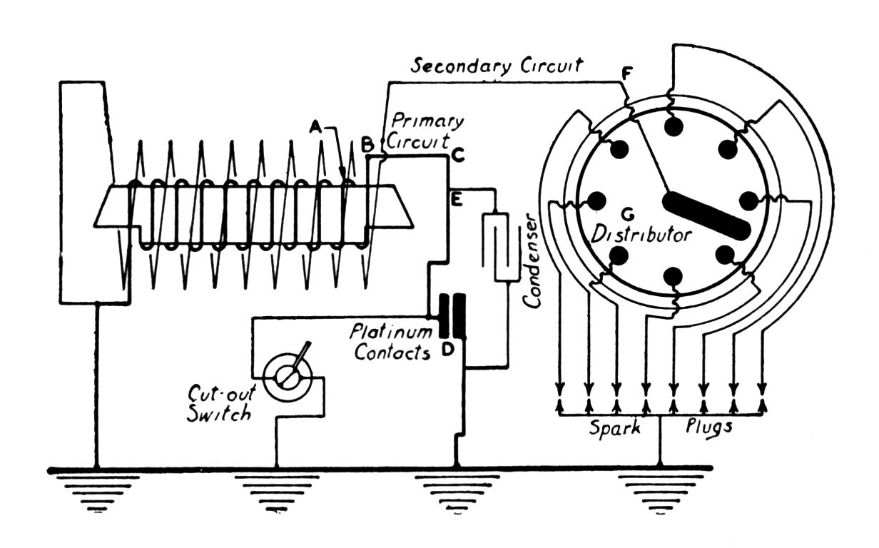
Each time the coil's magnetic field reverses, a current is induced in the primary circuit, which flows through the primary winding of the coil, through the contact points to the ground, and back its place of origin, completing the circuit. A condenser shunted across the contact points helps prevent burning. The contact points open just as the magnetic flux through the core changes direction, which collapses the primary current and induces a secondary current to flow through the secondary winding, distributor rotor, distributor, wires, and spark-plugs. Figure In-4 illustrates inductor magneto primary and secondary circuits.
The inductor magneto has mechanical and electrical improvements over the revolving-armature magneto in that the armature windings, breaker and condenser are stationary.
 |
 |
 |
 |
| Fig. In-1. Four-Pole Inductor Magneto Magnetic Circuit | Fig. In-2. Four-Pole Inductor Magneto Magnetic Circuit | Fig. In-3. Inductor Magneto Electrical Schematic | Fig. In-4. Two-Pole Inductor Magneto Magnetic and Electrical Circuits |
 |
 |
 |
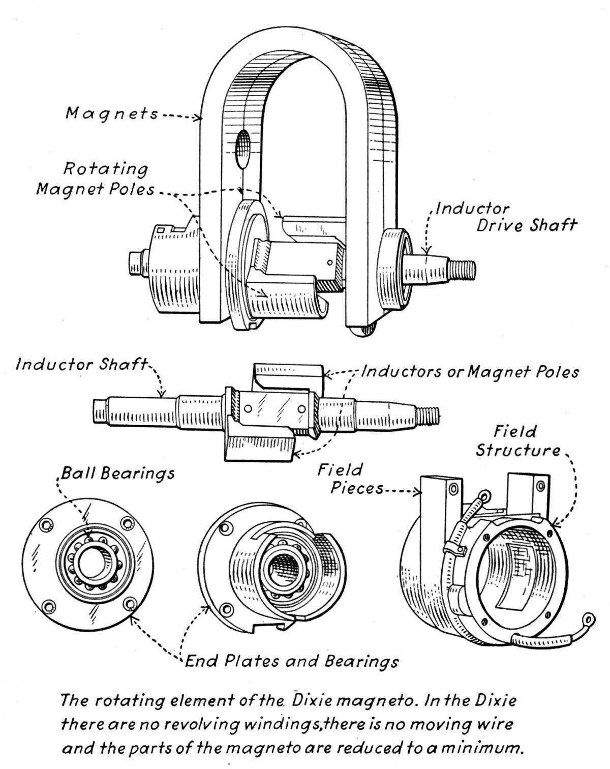 |
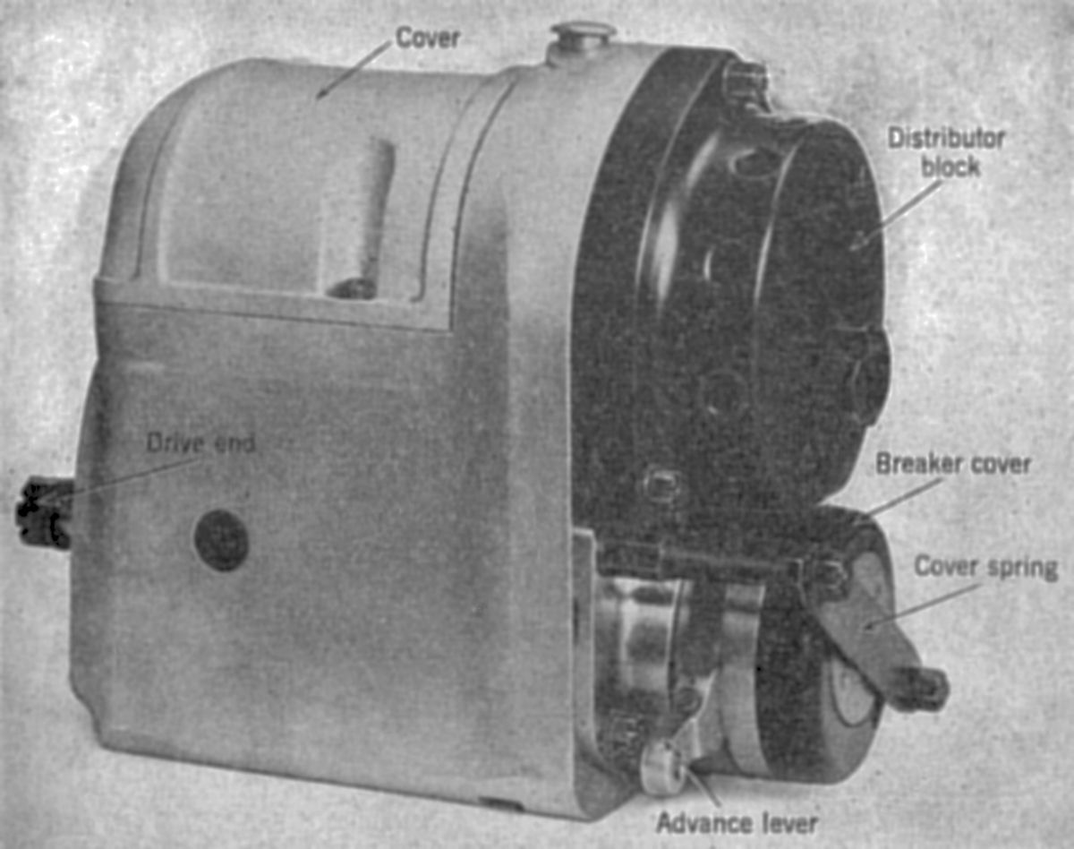
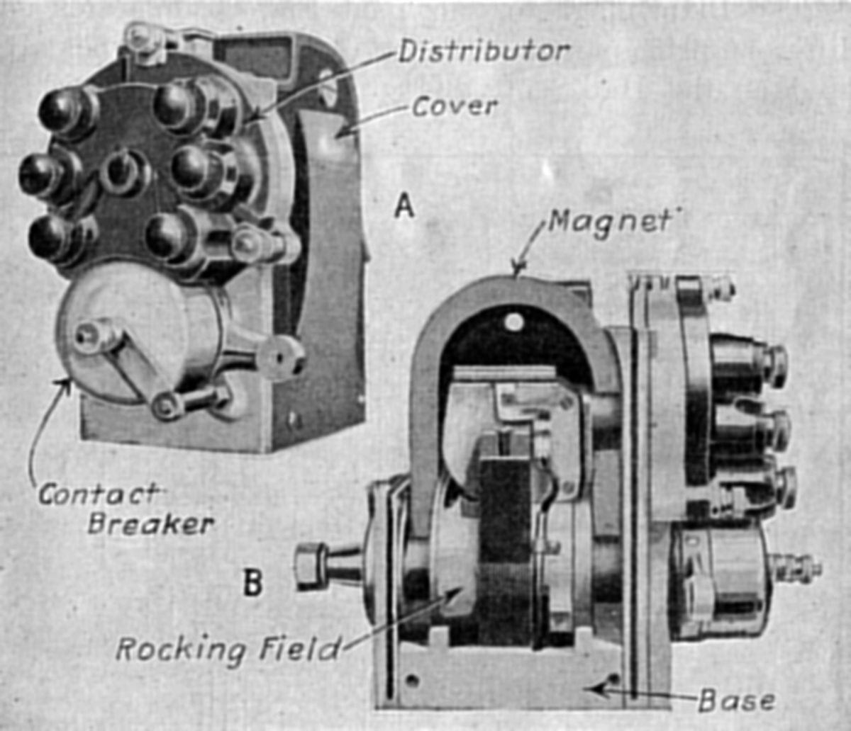
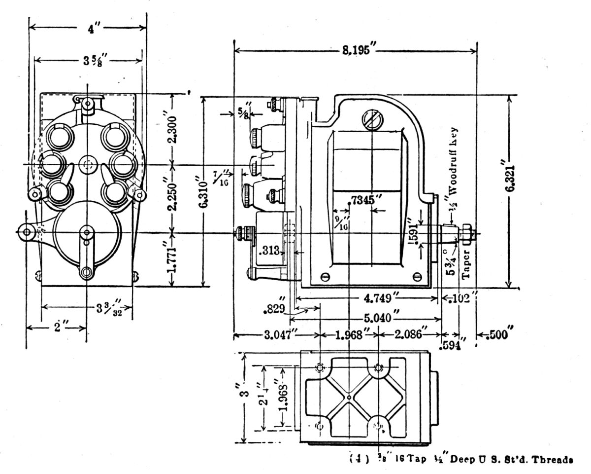
| Robert Bosch GF-9 Inductor Magneto | Dixie Magneto Construction | Dixie Magneto Dimensions | Dixie Magnetic Elements |
 |
 |
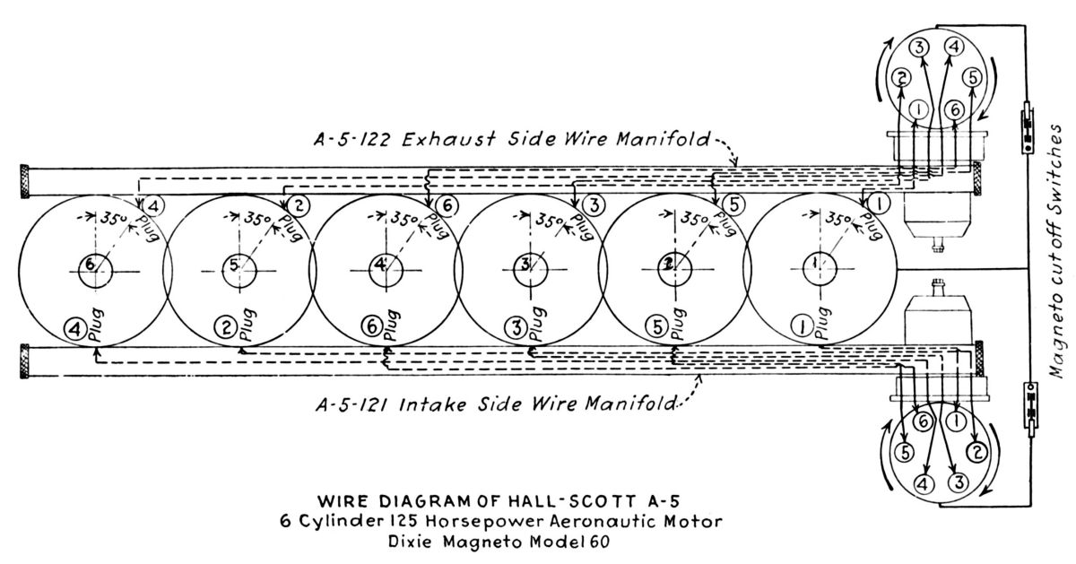 |
 |
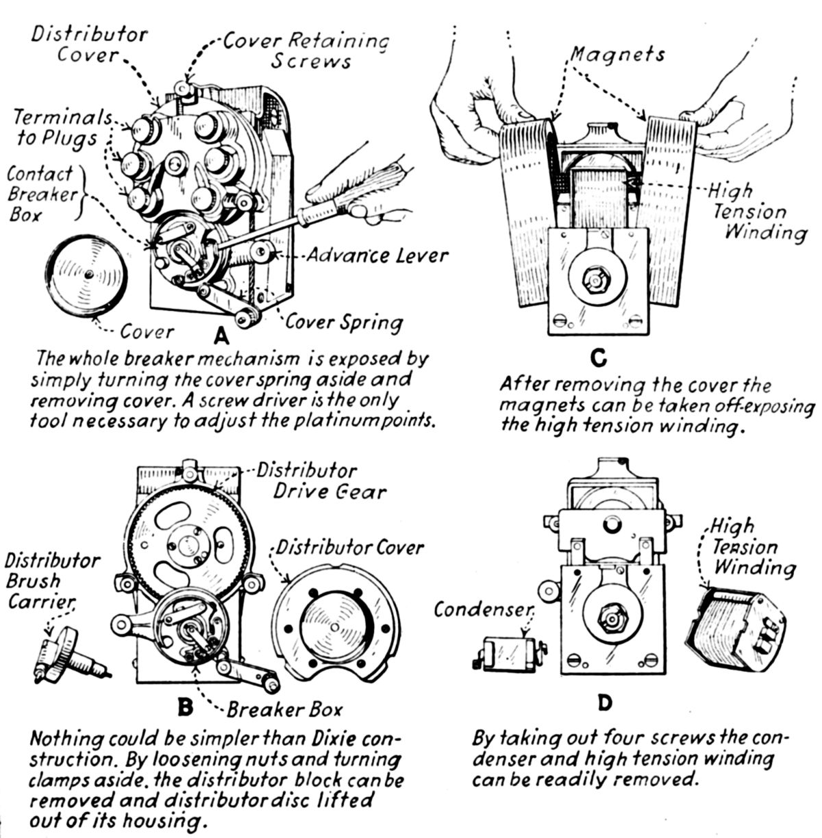
| Dixie Magneto Disassembly | Two-Pole Dixie Magneto Operation | Dixie Hall-Scott Engine Application | Splitdorf Four-Pole NS-9 Magneto |
 |
 |
 |
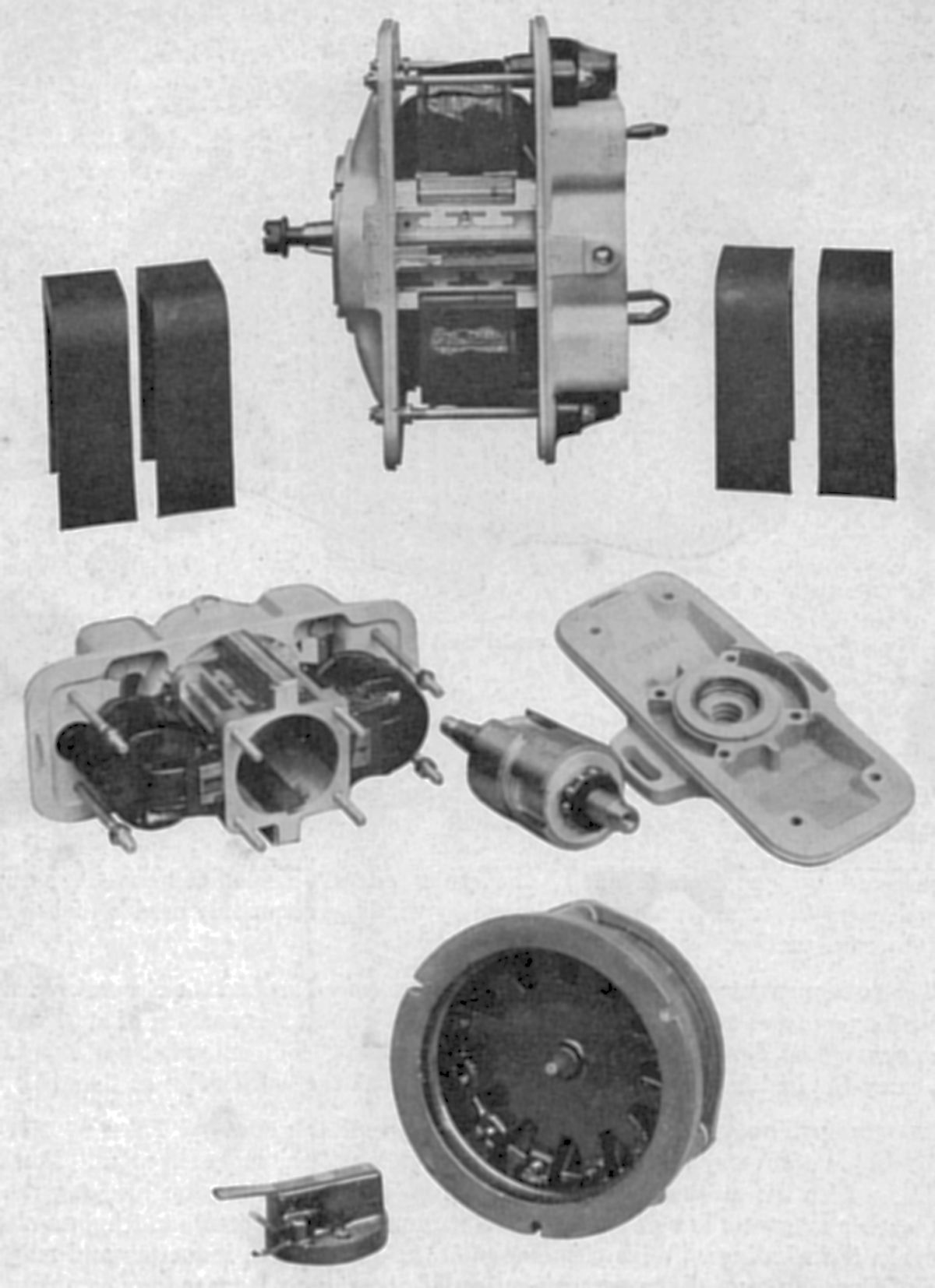 |
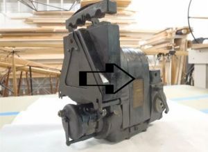
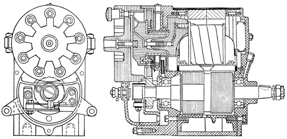
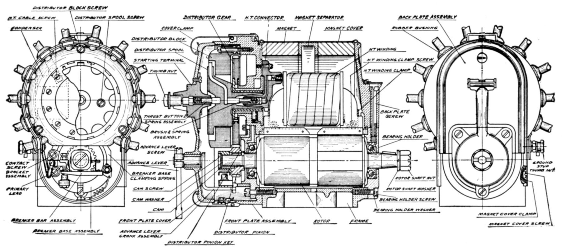
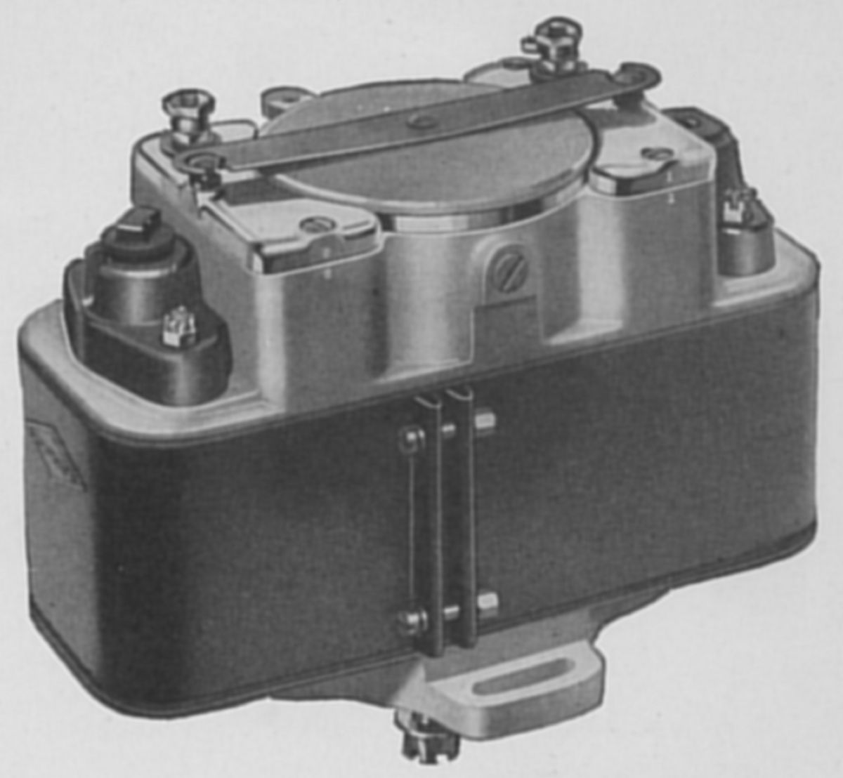
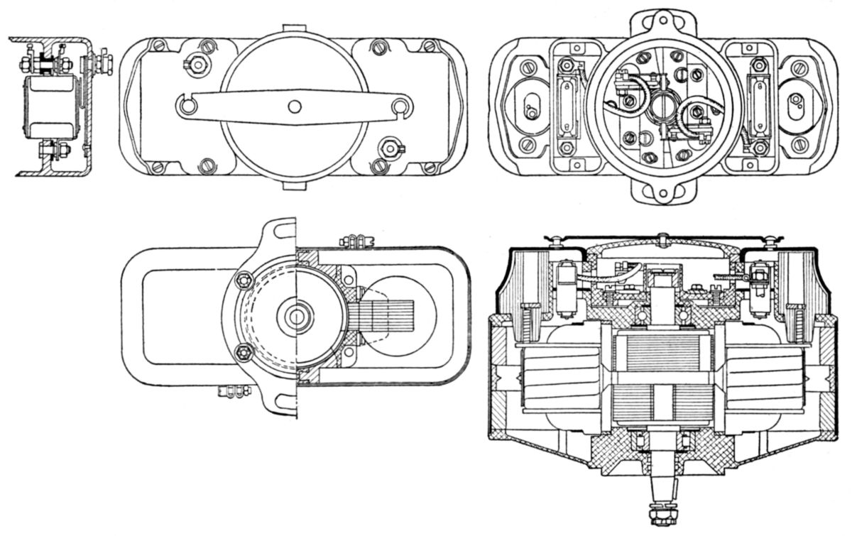
| Splitdorf SS-12 Magneto | Splitdorf VA Dual Magneto | Splitdorf VA Dual Magneto | Splitdorf VA Dual Magneto Top: Magnets, Frame with rotor and coils Middle: Frame and Rotor Bottom: Seperate Distrubutor and Rotor |
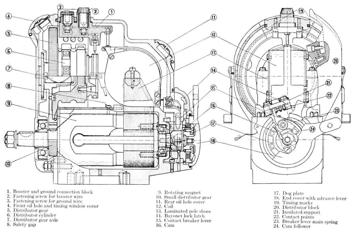
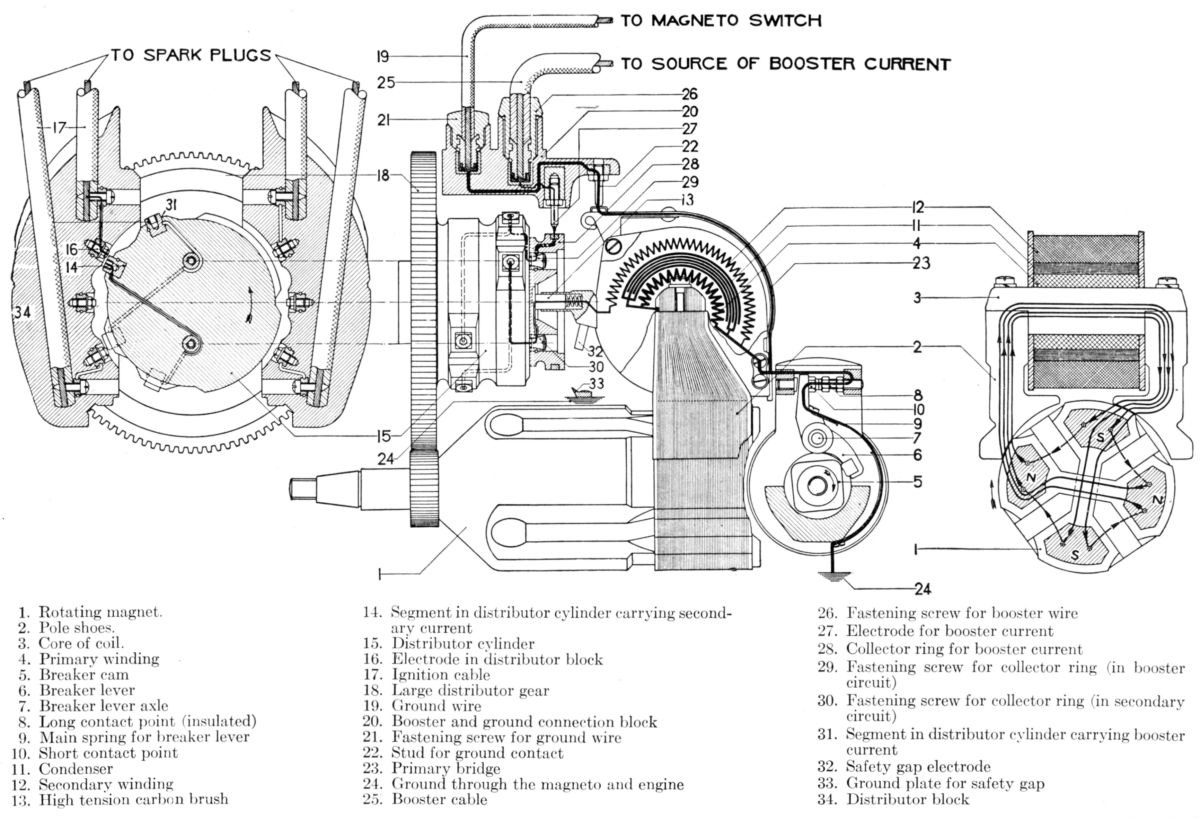
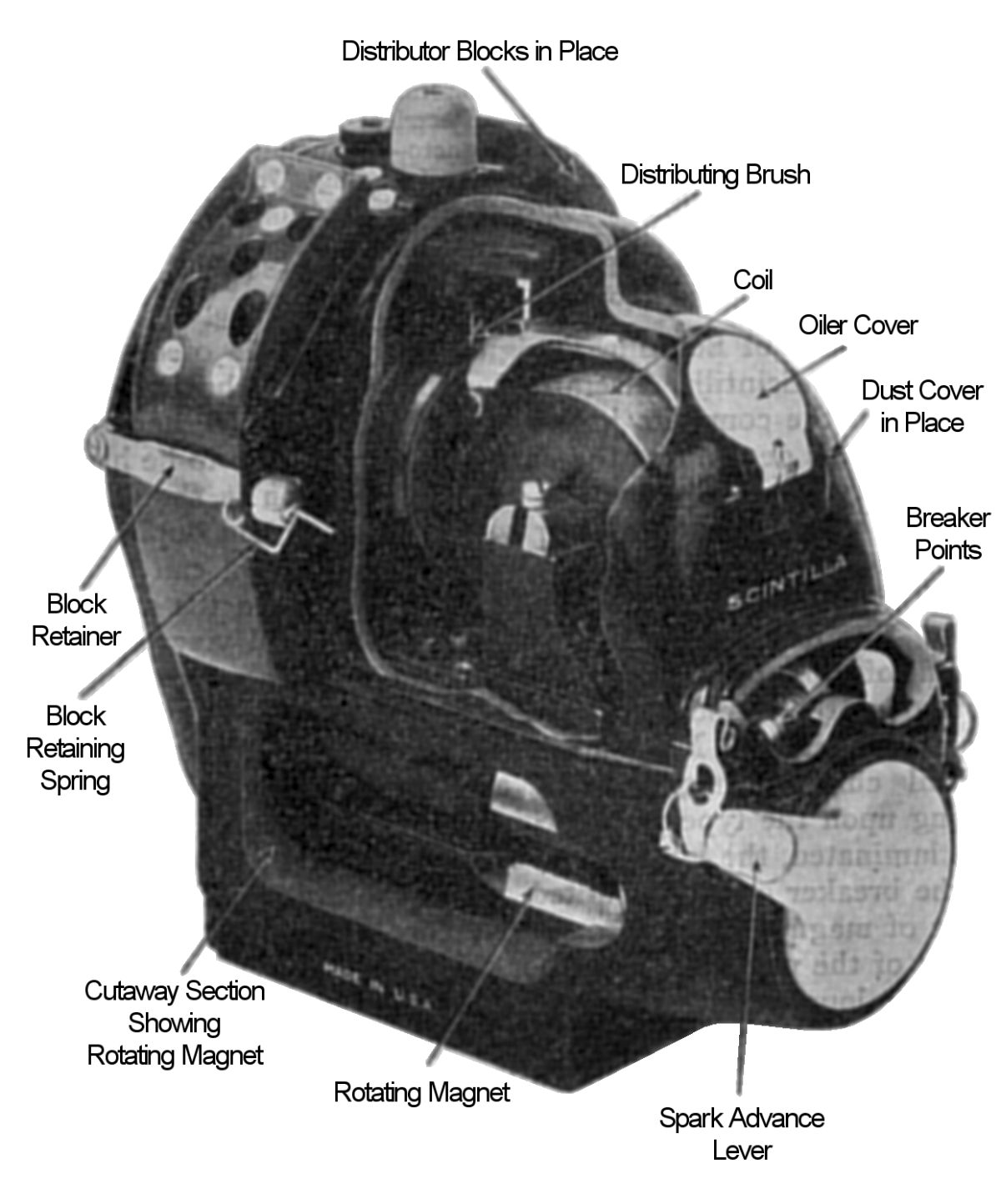
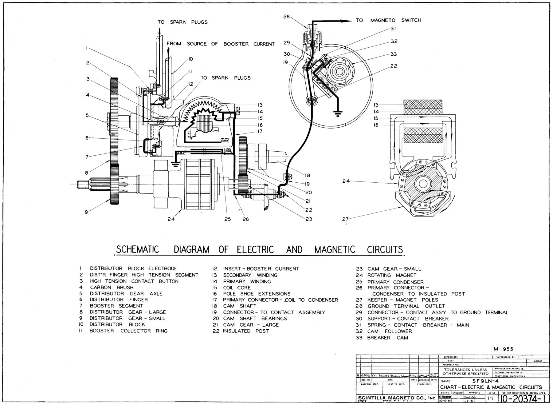
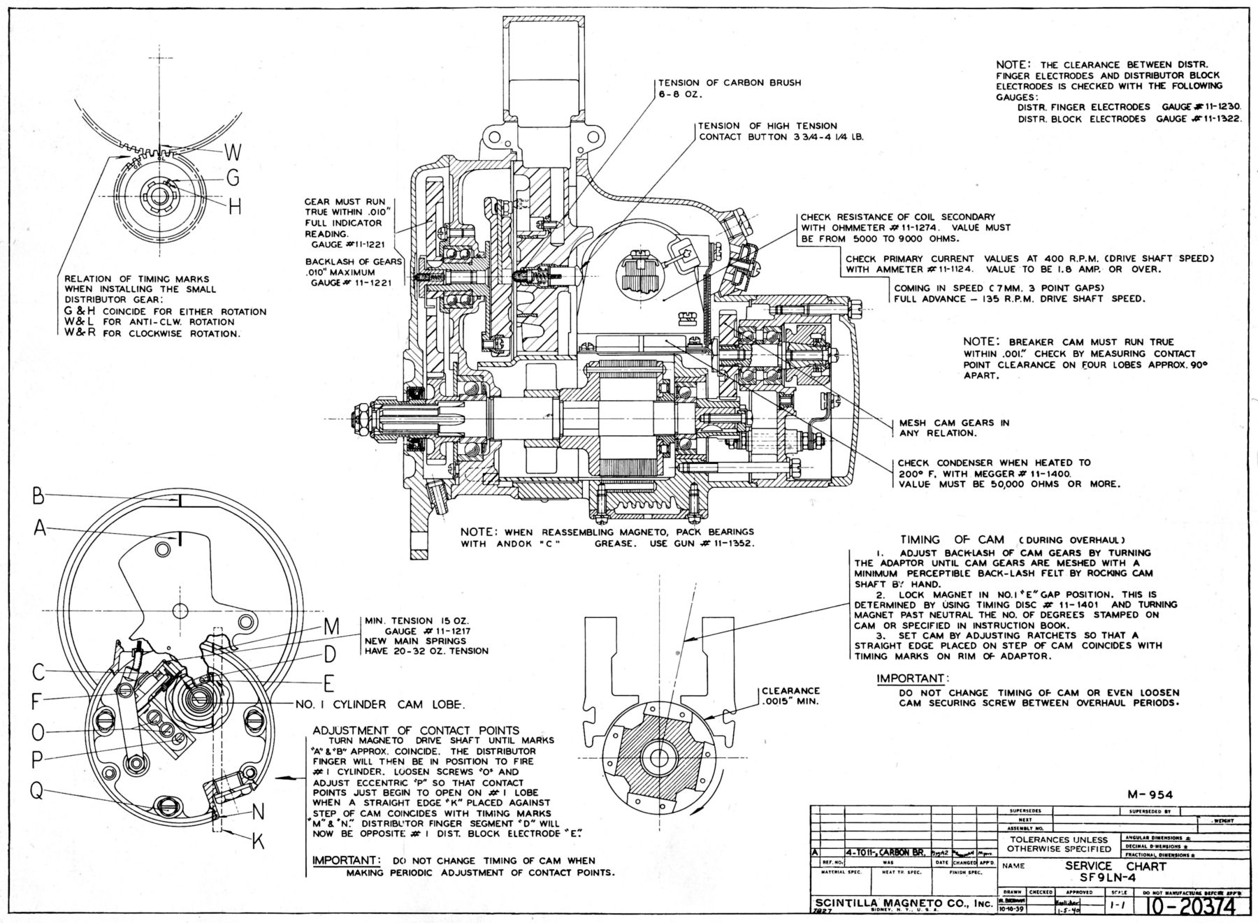
Rotating Magnet Magnetos
Rotating magnet magnetos retain all the advantages of polar inductor magnetos, but replace the large, heavy horseshoe magnets and with smaller and lighter rotating magnets. The rotating magnets can have two or more poles.
 |
 |
 |
 |
| Scintilla Magneto Parts | Scintilla Magneto Electircal and Magnetic Circuits | Scintilla Magneto Cutaway | Scintilla Magneto Parts |
Magneto Speeds
Magneto speeds depend upon the number of engine cylinders, the number of power strokes per crankshaft revolution, and the number of poles in the magneto rotating element. The table below shows representative magento speeds for various four-stroke engines.
| Engine Cylinders |
Magneto Poles |
Sparks per Crankshaft Revolution |
Magneto:Crankshaft Speed Ratio |
|---|---|---|---|
| 2 | 2 | 1 | 1:2 |
| 3 | 2 | 1 | 3:4 |
| 4 | 2 | 2 | 1:1 |
| 5 | 2 | 2.5 | 5:4 |
| 6 | 2 | 3 | 3:2 |
| 7 | 4 | 3.5 | 7:8 |
| 8 | 4 | 4 | 1:1 |
| 9 | 4 | 4.5 | 9:8 |
| 12 | 4 | 6 | 3:2 |
| 14 | 8 | 7 | 7:8 |
| 14 | 14 | 7 | 1:2 |
| 18 | 8 | 9 | 9:8 |
Compensating Cams
Large, high-power radial engines often employ compensating breaker cams to "compensate" for the master/articulated rod geometry imperfections, which cause the ignition event to vary from cylinder to cylinder. The breaker point cams are specially ground for each engine type so as to open the breaker points at the time appropriate for each cylinder. Additional internal gearing is employed to rotate the breaker point cam at 1/2 crankshaft speed.
 |
 |
| Representative 9-Cylinder Compensating Cam Magneto | |
Send mail to
![]() with questions or comments about this web site.
with questions or comments about this web site.
![]()