A Brief History of Aircraft Carburetors and Fuel Systems
Part 4: Float-Type Carburetors
by Terry Welshans
Bardstown, Kentucky
for the Aircraft Engine Historical Society
August 2013
Table of Contents
A carburetor has only one purpose, and that is to deliver a finely atomized fuel at the correct air-fuel ratio to the engine under all operating conditions. The carburetor mounts to the engine’s air induction system. The intake system is also called intake manifold. The carburetor often has an adaptor to match the opening and bolt patterns of the engine and carburetor base. A downdraft carburetor mounts above the engine and an up-draft carburetor mounts below the engine. Side-draft carburetors have a horizontal connection to the engine. Air entering the carburetor comes from a duct that extends into the airplane’s airstream, either at the front of the engine, or at its side. In some cases, the intake duct extends to the aircraft’s wings. Before the air enters the carburetor, it may pass through an air filter in some applications, and through a valve arrangement that allows hot air radiating from the engine exhaust pipe to mix into the air moving to the carburetor. This valve arrangement provides carburetor heat that prevents ice formation in the air duct and carburetor.[91]
|
|
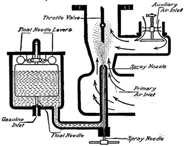
| Fig. 23. Carburetor Ice | Fig. 24. Early Float-Type Carburetor |
There are two types of proportioning carburetors and there are two types of fuel injection systems in use on aircraft. The simplest of the carburetors is the float-type. The other proportioning carburetor is the pressure carburetor. Fuel injection systems differ in how the fuel is distributed. One system continuously sprays fuel into the air induction system, the other sprays the fuel into the engine cylinder just when needed.
A carburetor is not only a vital component of an engine; it is an integral part of the power plant. The carburetor is precisely made and adjusted and provides the correct amount of fuel as determined by the amount of air flowing through the engine. The main component of any type of carburetor is the body, which is either a single large casting or a number of castings and machined components that form the body. The body generally contains the venturi(s) and throttle(s), with most of the sub-assemblies attached to it.
 |
 |
 |
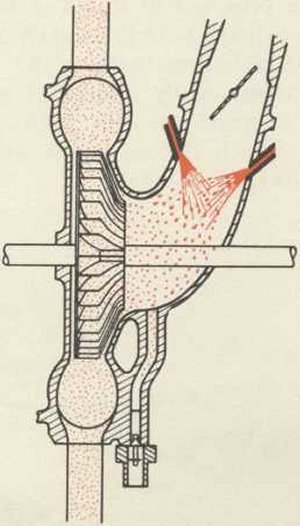
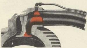
| Fig. 25. Fuel Injected into the Supercharger | Fig. 26. Fuel Injected into the Intake Valve Port | Fig. 27. Fuel Injected into Combustion Chamber |
| In fuel injection systems, a fuel injection pump sends fuel into the "eye" of the engine supercharger (left), the intake valve port (center) or directly into the combustion chamber via a fuel injection nozzle (right). | ||
The carburetor has two internal circuits; one is the air circuit, for the air flowing into the engine’s induction system, and the other, the fuel circuit, for fuel that mixes into the air flowing through the air circuit. The fuel circuit contains a number of individual sub-circuits.
Air Circuit
A carburetor air circuit includes the entire air intake duct. On some engines, the engine intake system includes a supercharger and a turbocharger. The carburetor throat has a venturi and a throttle valve that measures and controls the volume of air flowing through it.
Venturi
There are a number of ways of measuring the volume of air entering the engine. The method most commonly used is with a venturi through which the airflow entering the engine’s induction system. The same volume of air logically passes into and out of the carburetor. The cross section of the venturi is less than the remainder of the carburetor’s throat, and by use of Bernoulli’s formula, we know that the air velocity through the venturi must increase to pass that same volume of air.[92]
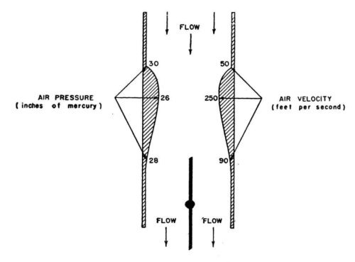 |
| Fig. 28. Carburetor Venturi |
The increase in velocity causes a pressure reduction that is in proportion to the air velocity. A low pressure in the venturi (a partial vacuum) indicates that high velocity air airflow is present. Because of this, the venturi’s variable vacuum represents the volume of air passing through it. This method of determining the volume of air entering the engine is much more reliable than most of the earlier methods. [93]
Throttle
In the Dec 18, 1944 NACA Memorandum Report No. L4L18, Flight Tests of the High Speed Performance of a P-51B Airplane (AAF 43-12105), T.J. Vogelwede and E.C.B. Danforth determined that on average, a 1,000 hp engine pumps 5,700 lb of air to create that much power.[94]
Using this hypothetical 1,000 hp engine as an example, the same ratio of one hp per 5.7 lb of air is the airflow for any size engine. In Aircraft Carburetion, by Robert H. Thorner, the author uses the formula one hp per 7.0 lb air, as his assumption is that one horsepower per hour will consume one pound of fuel and 7 lb of air.[95] The displacement of the engine, therefore, is not as important as the throttle setting, from idle up to 100% throttle, as for each hp produced, 5.7 lb of air will pass through the engine, and the throttle controls that airflow. See the venturi illustration for the throttle location on a typical float type carburetor. The ideal fuel-air mixture is 5.7 lb of air and one lb of fuel. A mixture that has slightly less or slightly more fuel will still produce power, but the efficiency of the engine will not be the same as when the best air to fuel ratio is used. Less fuel will result in less power, as the heat generated as it burns is less. More fuel will cool the combustion temperature, and that results in less heat, and therefore, less power. At high power levels, the combustion heat cannot leave the engine as fast as the heat created by the combustion. High cylinder temperature causes the spontaneous ignition of the unburned fuel. The heat released by the combustion process overheats the exhaust system and cooling systems. The heat that is retained within the engine raises the temperature of the cylinder wall, head and exhaust valve well above the ignition point of the fuel. The piston moves upward on the compression stroke, compressing the fuel-air mixture. The fuel undergoes autoignition when the temperature is above flash point of the fuel. Autoignition is preignition when it occurs before normal ignition or detonation when it occurs after normal ignition. Either detonation or preignition can destroy an engine, as the autoignition burn rate is about four times faster than that of normal combustion, creating forces that are much like the force from an explosion. The sudden heat and pressure released can melt engine parts such as aluminum pistons, thereby destroying the engine. Both of these conditions are included in detail, later in this article.[96]
The only way to measure the weight of air passing through an engine is to measure the density and volume of the air as it passes through the engine. See the table for air density at various altitudes. At low altitude, the air density is less important than the volume, as the air density changes gradually, and an aircraft that flies at less than 10,000 ft will most likely have a manual mixture control to compensate, as necessary. High power engines have an automatic device that measures air density. This device will internally compensate for altitude changes. Altitude compensation is included later in this article.
Fuel Supply
Fuel enters the carburetor inlet from the supply tank by either gravity, when the fuel tank is above the engine, or by an electric or engine driven pump when the fuel tank is below the engine. The fuel pressure from a gravity system will be the head pressure resulting in the difference in height between the fuel tank and the carburetor, typically around three to five psi. Fuel pumped from the wing or fuselage tanks to the carburetor is usually between five and twenty psi, depending on the aircraft and engine manufacturers specifications. Upon entering the carburetor, the fuel passes through a built-in filter, and enters the first of a number of metering jets.[97] The purpose of the first jet is to provide a constant fuel pressure to the main metering jet. The first jet, usually called the fuel inlet jet or inlet valve, is a variable size jet controlled by the level of the float in the fuel bowl. The metering orifice size changes as the conical point valve stem moves with the carburetor float.[98] As fuel leaves the fuel bowl, the float drops, along with the surface of the fuel, gradually opening the inlet jet, admitting fuel into the fuel bowl from the fuel supply system. Fuel continues entering the fuel bowl with the float following the level of the fuel in the fuel bowl, until the float is at the final fuel level, as determined by fuel consumption. When the engine slows, the fuel will continue flowing into the fuel bowl through the inlet jet until the float rises until the needle valve’s conical point reduces the fuel flow until it matches consumption. When the engine stops, the needle valve completely closes off the inlet jet, stopping the fuel flow into the fuel bowl. The purpose of holding a specific fuel level in the fuel bowl is to provide a constant fuel pressure to the fuel circuits. The fuel pressure within the carburetor is very low, as it is at the head pressure set by the depth of the fuel within the fuel bowl. This is a critical setting, as the pressure of the fuel at the inlet of the main jet will affect all of the fuel circuits, and fuel will flow at the wrong rate when incorrectly setting the float level. The fuel is now at the proper pressure and is available for use at the inlet to the main metering system.[99]
Fuel Circuit
The fuel circuit includes the parts and piping necessary to deliver fuel to the carburetor fuel inlet, at the proper pressure and volume. The fuel admitted through the float-type carburetor inlet valve is reduced to atmospheric pressure as the fuel bowl vent to the air inlet duct.
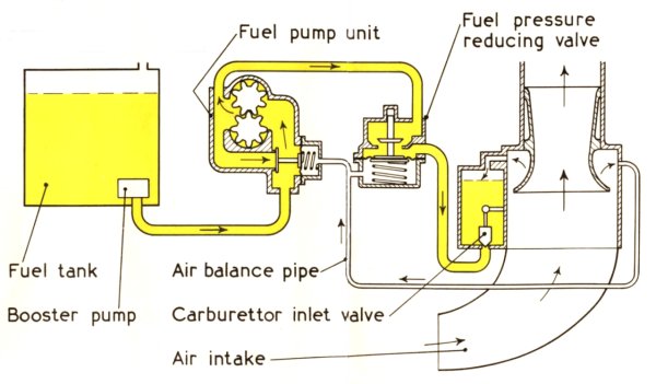 |
| Fig. 29. Basic Aircraft Fuel System |
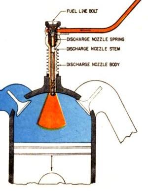
As the fuel bowl fills, the float rises with the fuel level until the fuel level in the fuel bowl is slightly below the level of the discharge nozzle. Once at the correct level, the float is high enough to close the inlet valve, stopping fuel flow into the carburetor at a precise height. This prevents fuel leaks into the intake manifold when the engine is not running. Fuel cannot enter the intake system unless intake manifold suction is sufficiently strong enough to lift the fuel up to the height of the discharge nozzle openings. On its way to the discharge nozzle, additional jets control the rate of fuel flow and pressure, as necessary. The drop in fuel pressure through the inlet valve classifies the valve as a jet.
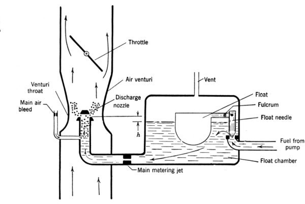 |
| Fig. 30. Float Level, Main Metering Jet and Discharge Nozzle. Note that the fuel level in the fuel bowl is slightly below the fuel discharge nozzle opening as identified by "h". |
Carburetor Jets
In a carburetor, a jet is a replaceable restriction that has a very carefully and accurately made orifice through it.[100] Generally, the term "jet" refers only to the orifice. In the jet shown in Figure 31, the flow is from the left, traveling through the jet’s orifice, to the right. A liquid flowing through a jet is similar to air flowing through a venturi. Hydrodynamic laws govern the flow through both, because gasses and liquids behave much the same as they are both fluids, and both fill all available space and move as necessary to do so. The primary differences between a liquid and a gas are the density, viscosity and compressibility of the fluid. A jet causes a reduction in pressure as the fluid flows through it, and the physical characteristics of the jet determine the amount of reduction. The diameter of the jet, as well as its length and shape regulate the flow through the jet. The angles and edge-sharpness of the conical area leading into and out of the jet, as well as the finish of the surface through the jet, all affect the flow through jets of the same size. In the case of the jet, instead of measuring the pressure at the jet’s narrowest point as in a venturi, it is the difference in pressure between a point before and a point after the jet that is measured.[101]
 |
| Fig. 31. A Typical Carburetor Jet |
Main Metering System
The main metering system begins at the main metering jet, which establishes a specific reduction in fuel pressure, as described earlier in the jet section of this article. The reduction in pressure will be constant, no matter how much fuel flows through the jet. The fuel flows to the main discharge nozzle, which is usually located in the center of the carburetor’s main airflow venturi. Often, the main discharge jet is located within a small secondary or boost venturi suspended in the center of the main airflow venturi.[102] The reduced air pressure in the venturi determines the amount of fuel drawn out of the discharge nozzle. The reduction in pressure is dependent upon the volume of air flowing through the venturi. The fuel will start flowing when sufficient differential pressure lifts the fuel from the fuel bowl level up to the level of the nozzle discharge openings. The amount of differential pressure controls the rate of fuel flow.[103] The main metering circuit will provide a constant fuel–air ratio at any engine speed and condition above the engine’s idle speed.[104] Experimentation found that admitting a small amount of air into the fuel passage to the discharge nozzle reduced the fuel droplet size, resulting in better fuel vaporization.[105] This is an example of an air bleed as the jet in the airstream controls the amount of bleed air admitted into the fuel passage.
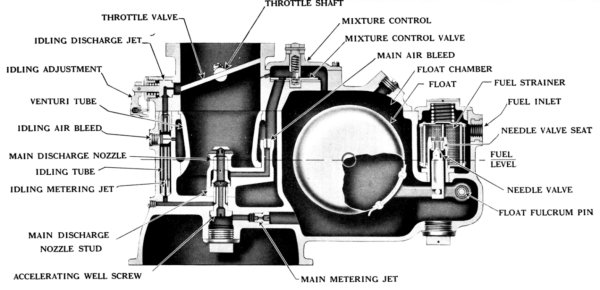 |
| Fig. 32. Stromberg Carburetor Cut-Away Detailing Its Construction |
Air Bleed
The inertia and viscosity of the fuel will cause a slight drag in the fuel flow as it moves through the small passageways within the carburetor. Providing a small amount of air into the fuel as it leaves the main jet helps reduce the drag. Figure 32 shows the air bleed into the main discharge nozzle passage. This air bleed does not change the amount of fuel flowing, as the air only assists the fuel as it flows upward to the discharge nozzle.[106] The air supplied to this air bleed system enters the carburetor through an air bleed jet that often has a tapered needle valve within it to adjust the bleed airflow. Other circuits within the carburetor use a similar air bleed circuit for the same purpose.[107]
Idle Circuit
When closed, the engine throttle has a very slight clearance that allows just enough air for the engine to operate at idle speed. With the throttle set at idle, the engine continues drawing whatever air is in the induction system into the engine cylinders, thereby reducing the pressure in the intake manifold. The volume of air flowing through the carburetor is very low, and there is not enough differential pressure to lift the fuel up to the outlet openings at the discharge nozzle. An alternate fuel circuit meters fuel when the throttle is at idle.[108] The idle system consists of a small drilled hole that connects the main air circuit past the throttle to the idle circuit jet, allowing the manifold pressure differential to draw fuel from the main metering fuel supply into the main air circuit. The idle jet often has a tapered needle valve within it to adjust the fuel flow. Some idle systems use an air bleed to control fuel flow, as shown in Figure 33. A small transfer orifice is located just before air passes the closed throttle plate, near when it is nearest to the carburetor’s wall. This feature is the "secondary idle orifice" in Figure 33. The transfer orifice connects to the idle circuit fuel supply. The orifice gradually transfers additional fuel into the main air circuit from the idle circuit fuel supply as the throttle transitions from closed to open. Both the idle passage and the transfer orifice are inactive when the air entering the pressure differential is below that needed to draw fuel into the idle circuit.
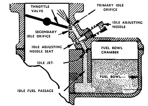 |
| Fig. 33. Marvel Updraft Carburetor Idle Circuit |
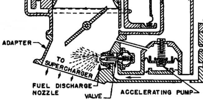
Accelerator Pump Circuit
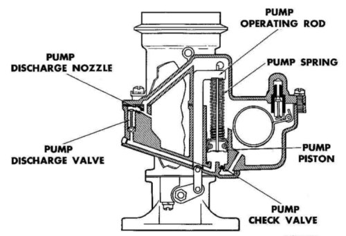
When the throttle is briskly opened, the idle passage no longer functions, as it relies on the high velocity air moving between the throttle plate and the idle passage outlet. Once the throttle opens, air quickly fills the intake manifold. With low engine speed, there is little air flowing through the carburetor. The transfer slot cannot provide enough fuel, nor can the main fuel discharge nozzle properly meter fuel, as there is a small delay as the fuel overcomes its inertia. The engine will falter slightly until there is sufficient vacuum in either the main or the idle circuit to start fuel flowing again. A small pump incorporated into the carburetor overcomes this lack of fuel flow.[109] It can be a vacuum operated diaphragm, a plunger or a simple well where extra fuel is available for that purpose. Early carburetors used an acceleration well. The well is a small amount of fuel located at the base of the discharge nozzle that is available as needed.[110] This fuel was limited to just the volume of the well, as it could only refill at a low rate. The plunger pump replaced the acceleration well. Either manifold vacuum or a mechanical linkage to the throttle operated the plunger. When mechanically operated, as the throttle is opened the pump plunger pushes a volume of fuel out of the pump, spraying it through passages leading to the main air circuit. "Pumping" the throttle would make subsequent volumes spray into the intake manifold, possibly flooding the engine with too much fuel, resulting in a fire. The linkage arrangement, the volume of the pump and the size of the spray nozzle outlet determine the characteristics of this accelerator pump.
 |
 |
| Fig. 34. Mechanical Accelerator Pump | Fig. 35. Vacuum-Operated Accelerator Pump |
A vacuum-operated accelerator pump has a diaphragm that creates a chamber within the carburetor body. Manifold vacuum pulls the spring-loaded diaphragm away from the fuel chamber wall, creating a fuel volume. Manifold vacuum is high when the engine is at idle with the throttle closed. When the throttle opens, the vacuum in the intake manifold drops to less than the diaphragm spring pressure, and the spring then pushes the diaphragm toward the fuel chamber. The fuel pushed out of the chamber enters the intake manifold through a nozzle opening. The size of the chamber, strength of the spring, area of the diaphragm and the size of the nozzle spray outlets determine the performance of the pump.
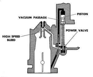
Power Enrichment Circuit
An engine operating at full throttle may not have enough rpm to create the necessary airflow, especially when operating under a heavy load. With a limited airflow and throttle wide open, the fuel mixture may not have enough fuel carried with it into the engine cylinder, causing a leaner than normal combustion which may then run hotter than normal. The engine may also run too hot when operating at full speed.[111] Extra fuel overcomes these problems. The fuel added to the normal mixture cools the cylinder walls as it evaporates just prior to combustion. This cooling lowers the fuel-air mixture temperature. The cooler mixture lowers the temperature and pressure in the combustion chamber, reducing the risk of detonation.[112] The extra fuel comes from the fuel in the fuel bowl. An enrichment valve and enrichment jet connect the fuel supply with the fuel delivery nozzle. The enrichment valve is either a mechanical linkage connected to the throttle, or a diaphragm lifted by the high venturi suction created by full-throttle operation, connecting the fuel bowl to the enrichment jet.[113] Some carburetor manufacturers refer to the enrichment circuit as an "economizer circuit", in that there is reduced fuel consumption when the valve is closed, thereby improving fuel economy at medium and low power levels. The engine now has the correct fuel-air mixture necessary for all operating conditions found at engine idle, take-off, and cruise power settings.
 |
| Fig. 36. Vacuum Operated Economizer Valve |
Mixture Control Circuit
Once at cruising altitude and speed, it is beneficial to reduce the amount of fuel consumed in order to increase range or for economic operation, and that is the job of the mixture control circuit. A manual control located near the pilot’s throttle control operates a device that changes the overall fuel–air ratio to a slightly leaner cruise mixture. Leaning the mixture at cruise power increases range and conserves fuel.[114] The lower power level and the available engine cooling allow operating with this leaner mixture, without causing harm to the engine. For that reason the lean setting should never be used when full power is needed, or may be immediately needed, such as when a landing turns into a missed approach, or when full power is needed to arrest a high sink rate.[115] The mixture control can provide a number of pre-determined mixture settings, and stops the engine at the conclusion of the flight or engine run. Mixture settings start at "Idle-cutoff", a position that closes the fuel passages, stopping fuel flow through the carburetor. The mixture changes from lean to rich as the mixture control moves to its full rich position.
There are two types of mixture controls. With manual mixture control, the mixture is set by hand, and has an infinite number of settings from full rich to full lean and cut-off. When moved to the rich position, fuel passes through the main metering jet and a jet with a variable size opening. Moving the mixture control toward the weak or lean position moves the valve gradually, reducing the size of the fuel orifice as the mixture control is moved. In carburetors equipped with automatic mixture control, fixed auto-rich and auto-lean settings control the mixture in place of the manually adjusted mixture control. The mixture control has three positions: idle-cutoff, auto-lean and auto-rich. These carburetors have two smaller jets connected in parallel, with the combined flow equal to the single main metering jet in non-automatic mixture control carburetors. In this type of carburetor, the larger jet is the lean jet and the smaller jet is the rich jet. Except when the mixture control is set to the cut-off position, the larger jet is always open. The smaller jet is only open when the mixture is in the auto-rich position. Another type of mixture control uses a vent valve to control the flow of air through the fuel bowl vent. This valve works much like the fuel control valve found in other mixture control systems, except that it controls the air pressure in the fuel bowl. Moving the mixture control opens or closes the fuel bowl vent to regulate the amount of vent air pressure in the fuel bowl for lean or rich conditions. Moving the mixture control toward the lean position slowly closes the fuel bowl vent. The pressure differential between the fuel bowl and the discharge nozzle is increased, and less fuel flows from the fuel bowl for a given air flow through the venturi. When the valve is in idle-cutoff position, the vent is completely closed and the amount of differential pressure is very high, and no fuel can flow from the fuel bowl.[116]
 |
| Fig. 37. Manual Mixture Control (top), Idle Mixture (bottom) |
A backfire occurs when either the burning fuel–air mixture leaks from the combustion chamber or a hot intake valve ignites the combustible mixture in the intake manifold. There are varying degrees of backfires, from a small fire to a fully involved fire or explosion. In 1932, the Allison Engine Company incorporated a number of preventative measures to prevent backfires in the V-1710, an engine designed to meet a very high level of performance using a high operating temperature. Under normal conditions, the combustion process is complete well before the intake valve opens, but with an intake valve that is not completely closed, the high pressure, high temperature combustion gasses escape from the combustion chamber through even a slight opening between the intake valve and its seat.[117] It can be very difficult to find the exact cause of a backfire as there are often multiple causes, and at times more than one cause occurs at the same time.[118]
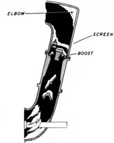
When a backfire occurs, the combustible mixture literally explodes in the intake manifold. This results in serious damage to the engine. One way to prevent the flame extending from the cylinder into the intake manifold is to install a metal screen at the intake port of each cylinder, or group of cylinders.
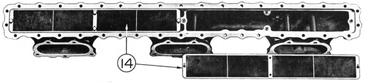 |
| Figure 38. Rolls-Royce Merlin Flame Traps (14) on Intake Manifold. This flame trap does not prevent backfires; it only keeps the flame from entering the intake manifold. Unfortunately, it also adds a restriction that lowers the efficiency of the engine, resulting in a loss of power.[119] If the engine is not precisely tuned to the factory specifications and operated according to the manufacturers approved procedures, removing the flame traps from the intake manifold will improve engine performance, but at the risk of damage.[120] |
Properly designed spark ignition engines have an orderly flame front that moves through the fuel–air mixture in the combustion chamber, resulting in a controlled increase in gas pressure. Under certain conditions, rapid oxidation reactions occur within the unburned charge, leading to very rapid combustion throughout the charge. This heat release is from the auto-ignition of the fuel-air mixture. The very rapid pressure rise results in the characteristic sound of engine knock or ping.
Preignition
Preignition is the spontaneous or autoignition of the fuel–air mixture before the spark plug fires. Preignition is similar to the fuel ignition process found in a diesel engine. In a diesel engine, fuel injected into a volume of air heated by compression to well above the ignition temperature of the fuel instantly ignites. Test have shown that the temperature of the inlet airflow at the cylinder is one of the more-important causes of preignition, as the temperature rise from the heat of compression is fairly constant at a given compression ratio, regardless of the inlet airflow temperature. This means that a high inlet temperature will result in a correspondingly higher than normal temperature in the compressed mixture as the piston approaches the top of its stroke. When the inlet temperature plus the temperature increase from compression reaches the ignition temperature of the fuel–air mixture, it spontaneously ignites with a flame front velocity as much as four times that of the flame front velocity found in normal combustion. This ignition, similar to that of an explosion within the cylinder, occurs well before the timing of normal ignition, which is usually 20° ~ 35° before top dead center. This explosion, well before top dead center, can cause sufficient force to turn the crankshaft in the opposite direction. It may bend or break the connecting rods or even break the crankshaft, thereby causing a great loss of engine power. The resulting heat is often severe enough to melt aluminum pistons, which leads to cylinder wall damage, and ultimately, total engine failure. Setting the fuel–air mixture richer than that necessary for normal combustion reduces the risk of preignition. The mixture first lowers the inlet air temperature by evaporation, and that lowers the speed of flame front, as a rich mixture burns lower than a normal mixture. The richer mixture also reduces the aircraft’s range due to the higher fuel consumption.[121]
Pre-ignition, as the name implies, means that combustion takes place within the cylinder before the timed spark jumps across the spark plug terminals. Excessive carbon or other deposits cause local hot spots. However, high-power operation on excessively lean mixtures may also cause pre-ignition. Pre-ignition causes engine roughness, backfiring and a possible sudden increase in head temperature. [122] Any area within the combustion chamber becoming incandescent will serve as an igniter in advance of normal timed ignition and cause combustion earlier than desired. Pre-ignition from an area roughened and heated by detonation erosion is also possible. A cracked valve or piston, or a broken spark plug insulator may serve as a "glow plug," furnishing an ignition hot spot. Leaded fuel deposits and normal carbon deposits can also cause pre-ignition. Specifically, pre-ignition is a condition similar to that caused by incorrectly timing the ignition system. The charge in the cylinder ignites before the time required for normal engine operation. Do not confuse pre-ignition with ignition too early in the cycle. Verify that the cause of the preignition is incorrect ignition timing. It is far more likely that a hot spot or a hot combustion chamber results in pre-ignition. The hot spot may be due to either an overheated cylinder or a defect within the cylinder.
Pre-ignition caused by a damaged component in the combustion chamber, such as a spark plug, is a serious condition. In such cases, the engine should be operate at a greatly reduced power setting or be shut down altogether. If the engine is at high power when pre-ignition occurs, retarding the throttle for a few seconds may provide enough cooling to chip off some of the lead, or other deposits within the combustion chamber. These chipped-off particles will pass out through the exhaust and are visible at night as a shower of sparks. If retarding the throttle does not permit uninterrupted power operation, a sudden cooling shock treatment may remove some of the deposits. Such treatments include using water injection, alcohol from the de-icing system, full-cold carburetor air, or any other method that provides sudden cooling to the cylinder chamber.
Detonation
Detonation is the spontaneous ignition of the fuel charge after normal ignition, and results in the same damage to the engine as preignition.[123] One explanation of the cause of detonation is "pressure piling," a phenomena that is related to the combustion of gases in a tube similar to an engine cylinder. As the flame front propagates along the tube, the unburned gases ahead of the flame front become overly compressed, and are thereby overheated. The amount of compression varies depending on the geometry of the cylinder and can range from twice to eight times the initial compression pressure. Once the heat raises the temperature of the after-gas to the ignition point of the unburned fuel, a "deflagration to detonation transition" produces very high explosive pressure and heat within the combustion chamber.
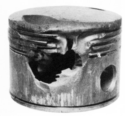 |
| Fig. 39. Piston Burned by Detonation |
Either preignition or detonation can result in serious damage to the engine and its eventual failure if not brought under control. Detonation of the fuel–air charge in a reciprocating engine is the principal factor limiting the maximum power produced by an engine.[124] Using fuel with a known resistance to detonation reduces the risk of detonation. The engine’s design determines the octane or performance number required for best performance.[125] Detonation-free operation is not solely dependent on fuel properties. Factors such as charge temperature, mixture strength, ignition timing and spark plug type can also affect the combustion process in an engine. There is a limit, however, to the amount of compression and the degree of temperature rise tolerated within an engine cylinder that still permit normal combustion. All fuels have critical limits of temperature and compression.[126] Beyond this limit, the fuel will ignite spontaneously and burn with explosive violence. The explosive burning during detonation results in an almost instantaneous very high temperature, and when combined with the high turbulence generated by the explosion, causes a "scrubbing" action on the cylinder and the piston. Unless detonation is heavy, there is no cockpit evidence of its presence. Light to medium detonation does not cause noticeable roughness, temperature increase or loss of power. As a result, it can be present during take-off and high-power climb without detection by the crew.
Sometimes, overhaul may find that detonation has damaged the engine. The presence of detonation its often indicated by dished piston heads, collapsed valve heads, broken ring lands, or eroded portions of valves, pistons, and cylinder heads. The basic protection from detonation is in the carburetor mixture setting, which automatically supplies the rich mixtures required for detonation suppression at high power, the rating limitations, which include the maximum operating temperatures and the selection of the correct grade of fuel. The engine design factors considered include cylinder cooling, ignition timing, mixture distribution, supercharging, carburetor setting incorporated in the design and development of the engine and its installation in the aircraft. The engine manufacturer must prove to the satisfaction of the procuring or regulating government agency that engine operation is free from harmful detonation, and that it can operate under most adverse conditions, within the listed limits of operation and the engine is in top condition. In addition, the aircraft manufacturer must demonstrate that the power plant installation will permit safe operation of the engine within the established limits throughout the performance range of the airplane.[127] The remaining responsibility for prevention of detonation rests squarely in the hands of the ground and flight crews, as they are responsible for observance of rpm and manifold pressure limits. Proper use of supercharger and fuel mixture, and maintenance of suitable cylinder head and carburetor-air temperatures are entirely in their control. In the most cases, the operator must accept these limitations on faith, as detonation may be present and not indicated by the instruments when either on the ground or in the air.[128]
Carburetor ice can form well above freezing temperatures, even when there is low relative humidity. A sudden reduction in air pressure lowers the air temperature, and if moisture condenses, ice forms, a condition found in the engine intake manifold when the throttle is closed, or when operating the engine at a low power setting.[129] Air moving through the carburetor venturi and throttle is at or near atmospheric pressure and temperature, but once past the throttle, the air pressure drops, resulting in the air giving up heat, cooling it. If the initial temperature is only a few degrees above freezing, the temperature will drop to less than freezing. Whatever moisture that is present in the air will first condense into liquid that freezes to the chilled throttle or intake manifold surfaces. A similar condition exists as fuel is evaporated, absorbing heat from the surrounding fuel and air. Again, the temperature may drop below freezing, and ice will then form at the fuel nozzle. Under some conditions, such as when a light aromatic fuel is used, cooling up to 150°F is possible, although cooling of 70°F is more common. For every 20°F drop in temperature, the relative humidity of the air in the carburetor doubles. When the relative humidity reaches 100%, it starts raining inside the carburetor, and if the temperature is 32°F or less, the rain becomes ice. Should the air entering the carburetor be colder than freezing, it may already contain super-cooled liquid water. This water will instantly freeze to any cold surface, forming ice. This ice can form in the air intake duct, choking the airflow and causing a loss of power.
Carburetor Heat
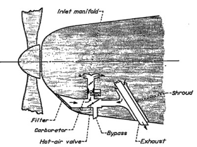
One solution to carburetor or air intake icing is to prevent it before it forms by venting a regulated amount of warm air into the air intake duct, before the airflow enters the carburetor. The heat for this system comes from air flowing through a heat exchanger that takes heat from the engine exhaust, or from the hot air within the engine cowling.
 |
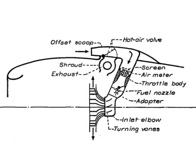 |
| Fig. 40. Manifold Heat on Light Aircraft | Fig. 41. Manifold Heat on Large Aircraft |
Warm air is less dense than cold air, and this causes a reduction in engine power as the less dense warm air contains less oxygen as well as weighing less than cold air. Although carburetor heat is necessary, its use results in a loss of engine power. Consult the engine and aircraft manuals for proper use. As engine power became available, aircraft could fly at increased altitude. As altitude increases, air pressure, density and temperature all become lower. The temperatures encountered above 20,000 ft are well below freezing, and can be tens of degrees below 0°F. The clouds encountered in this rarified air are composed of ice crystals, and even in clear air, the moisture released through the engine exhaust system condenses and freezes into graceful contrails. Graceful that is, unless enemy gunners happen to be below your bomber, as the contrail points out your aircraft from an otherwise clear sky.
Carburetor Deicing Fluid
A second method of removing and preventing carburetor ice is the use of a deicing fluid. Antifreeze fluid-injection systems supplement other carburetor heat systems that may be deficient under some operating conditions or for emergency deicing if the normal system fails.
Because most deicing fluids now used are inflammable, such systems are operational hazards. Ethanol and isopropanol are among the deicing fluids that have been used. Commercial deicing fluids consist of a mixture of ethanol, methanol, denaturants, and sometimes a rust inhibitor. Ethanol and isopropanol are very similar in physical properties, but the ethanol provides greater freezing-point depression. Addition of some types of deicing fluid to the charge air reduces the octane rating of the fuel-air mixture, with detonation and consequent reduction in the available power and in severe cases may damage the engine. Variations among induction systems, such as the method and the point of injection, along with the type of deicing fluid used are critical factors in obtaining the most effective ice removal. Spraying the deicing fluid into the air stream as close as possible to the ice formation provides a large concentration of undulated fluid at the ice formation. Spraying the fluid into the air immediately above the carburetor removes only the ice formations downstream of that location.
The deicing fluid flow rate varies with different induction systems and the type of ice present. Given a relatively clean system with few protuberances or irregularities in the carburetor air passage, the throttle at cruise power, 40°F carburetor-air temperature and at 4,000 pounds of air per hour, a deicing fluid flow of 1 ~ 2% of the airflow insures throttling and fuel evaporation ice is removed within approximately 5 minutes after initial application. Fluid deicing investigation of a different configuration showed similar recovery times for conditions of icing-air temperature and fluid flows comparable to those used for the investigation of cruise-power conditions. For rated-power conditions with impact icing at 25°F, full recovery within 5 minutes could not be accomplished in the second configuration with fluid flows as high as 1% of the airflow. An investigation of a larger induction system showed that deicing-fluid flows in excess of 1% of the airflow were required to remove impact icing alone.
Alcohol vapor was a potential deicing agent. This method gave slow recoveries and part of its small success do to the release of latent heat to the air stream by the vapor when it condensed. An analytical method determined the theoretical minimum amount of alcohol required to prevent carburetor icing or to compare the merits of fluids of determent composition. This method considers a number of factors, including the amount of alcohol required to lower the freezing point of water to the minimum surface temperature existing in the system, the adiabatic temperature drop due to throttling, the kinetic rise in the surface boundary layer, and the cooling effect of the evaporation of the deicing fluid. This method determines only the minimum rate of deicing fluid as perfect distribution of the fluid. British investigators have reported considerable success eliminating fuel-evaporation icing by injecting alcohol with the fuel at a rate of from 2 ~ 5 % of the fuel consumption rate. If alcohol is added to the fuel supply, it must be free of water to prevent separation of the alcohol and the fuel.
In general, a fluid deicing system is inadequate and unreliable as a sole means of ice protection, and is an emergency deicing method. The recoveries obtained with heated air are usually much faster than the recoveries obtained when using a deicing fluid. If a fluid deicing system is to be need, it should be carefully designed both to satisfy the particular ice-prevention requirements of the induction system in which it is to be installed and to minimize the potential hazard common to this system of protection. Take precautions to insure positive shut-off of the alcohol system on engine shutdown to prevent accumulation of alcohol-vapor in the induction system. The results of many fluid deicing experiments indicate that the requirements of each individual induction system must be separately determined with particular scrutiny of the spray characteristics of the nozzles used and the distribution of the fluid. There are several chemicals available to deice aircraft carburetors. Most of these chemicals are mixtures of isopropyl alcohol and methyl alcohol. Some brands include additional chemicals in small amounts. These fluids remove the ice by lowering the freezing point of the water, melting the ice that has formed and preventing ice as long as the fluid is flowing. There is a limit to the amount of fluid available; thereby limiting the amount of time that it is useable, as determined by the flow rate and pressure.
Both hot air and fluid deicers were tested and compared on a typical air induction system.[130] The study found that the liquid deicers all worked to varying degrees, and all were corrosive on aluminum. When compared to heated air, they were less effective at returning the airflow to normal. These simulated tests were in typical ice-producing conditions where the raw inlet air temperature and atmospheric pressure were controlled, and water spray simulated the moisture levels found under various conditions. The test setup used a variety of equipment to provide normal cruise airflow through the carburetor, heat and cooling where needed, and special test apparatus for taking measurements at various locations. The induction system tested consisted of a simulated air scoop, a Holley 1375H carburetor, a carburetor adapter, and a Wright R-1820 G-200 supercharger rear section. The deicing fluid injection devices used included the standard Holley alcohol vent ring (Holley Part No. 2383), a modified Holley vent ring (Holley part No.3089, a set of four standard Army nozzles (part AN-4023 and AN-4024), and a set of modified Army nozzles which were similar to the standard nozzles except for larger exit orifices.
The deicing fluids tested were Solox D-isopropyl alcohol®, anhydrous ethyl alcohol, S.D. 30, Shellacol®, and I. In most of the tests, maintaining the carburetor-air temperature at 40°F while spraying free water into the air stream at a rate of 250 grams per minute produced refrigeration icing. Overall, the best liquid deicer was isopropyl alcohol injected through US Army standard deicer spray nozzles into the airstream about two inches above the carburetor intake. High altitude conditions compounded the ice problem, indicating the need for a new type of carburetor. Enter the"floatless carburetor" and the "pressure carburetor" specifically designed for this application.
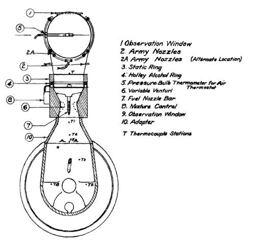 |
| Fig. 42. NACA Deice Fluid Test Equipment |
Endnotes
[91] Cessna 152 Information Manual, p 3-7.
[92] Aircraft Carburetion, pp 35-38.
[93] Aircraft Carburetion, pp 35-38.
[94] NACA Memorandum Report No. L4L18, p 14.
[95] Aircraft Carburetion, p 50.
[96] The Aircraft Engine and its Operation, pp 27, 28.
[97] Manual of Stromberg Aircraft Carburetors, p 8.
[98] Manual of Stromberg Aircraft Carburetors, p 13.
[99] Manual of Stromberg Aircraft Carburetors, p 13.
[100] Manual of Stromberg Aircraft Carburetors, p 38.
[101] Manual of Stromberg Aircraft Carburetors, p 38.
[102].Manual of Stromberg Aircraft Carburetors, p 17.
[103].Aircraft Carburetion, pp 59, 61.
[104] Aircraft Carburetion, p 63.
[105] NACA Technical Report No. 49, p 603.
[106] Aircraft Carburetion, p 61.
[107] Aircraft Carburetion, p 61.
[108] Manual of Stromberg Aircraft Carburetors, p 19.
[109] NACA Technical Report No. 11, p 68.
[110] Manual of Stromberg Aircraft Carburetors, p 7.
[111] NACA Technical Memorandum No. 853, pp 5-7.
[112] NACA Technical Memorandum No. 853, pp 5-7.
[113] Aircraft Carburetion, pp 72-73.
[114] Aircraft Carburetion, p 74.
[115] The Aircraft Engine and its Operation, p 31.
[116] Manual of Stromberg Aircraft Carburetors, pp 21-24.
[117] Vee’s For Victory, p 114.
[118] Investigation Report 200002157, pp 33-38.
[119] Vee’s For Victory, p 114.
[120] Investigation Report200002157, pp 33-38.
[121] NACA Technical Memorandum No. 853, p 5.
[122] Engine Conditioning For Reciprocating Engines, pp 13-14.
[123] NACA Technical Memorandum No. 853, pp 5-7.
[124] NACA Technical Report No. 647, 1938, pp 1-2.
[125] NACA Technical Report No. 647, 1938, pp 1-2.
[126] Engine Conditioning For Reciprocating Engines, pp 12-13.
[127] FAR and EASA regulations on Detonation.
[128] FAR and EASA regulations on Detonation.
[129] FAR and EASA regulations on Detonation.
[130] NACA Advance Restricted Report No. 3H13, pp 1-3.
Send mail to
![]() with questions or comments about this web site.
with questions or comments about this web site.
![]()