Evaporative Cooling – The Racer’s Edge
Part 1: Through WWII
by Daniel D. Whitney and Peter V. Law
Published 3 Jan 2018
 |
This article first appeared in The Journal of the Rolls-Royce Heritage Trust, in two parts. Titled: "Evaporative Cooling – The Racer’s Edge"; Issue No. 6, December 2016 and Issue No. 7, May 2017. The article was inspired by David Birch of the R-RHT. The authors hope that readers will better appreciate the history and technology of some of the efforts that have been made to go really fast in a piston powered aircraft.
|
Going fast, really fast, in an airplane is more than sleek aerodynamics. Not only must the airframe be meticulously “clean”, but every system needed for flight must also be tuned for speed, not just the engine. The unfortunate truth is that a reciprocating engine is not very efficient, as only about 25 % of the energy in the fuel results in horsepower into the propeller, with another 25 % needing to be removed by the engine’s cooling systems, and a huge loss of about half of the energy leaving with the hot exhaust gasses.
Airframe builders, designers and racers have all worked to minimize these losses: properly shaped exhaust stacks can develop considerable jet thrust from the exiting gasses while carefully sculptured propellers can improve the efficiency of getting the engine horsepower into the air. Even so these efforts are usually overshadowed by the drag on the airframe caused by the necessity of nearly stopping the high speed air coming in to cool the radiators and oil coolers. This is not only practical but necessary on aircraft intended to cover reasonable distances while carrying a useful payload. Neither of these last two requirements is really necessary for aircraft intended on breaking speed records, particularly the Fédération Aéronautique Internationale Class C-1 Group I 3-kilometer course specified for a world record by the FAI sanctioning body. An alternative is to evaporate a volume of liquid to carry the heat away. While the benefits of such a system are specific to the capabilities of the airplane involved, the potential payoff can be rather impressive. For example, it was anticipated that the Messerschmitt Bf 209 would gain 80 km/hr (50 mph) by the use of its evaporative system.
For such records, and for even the Reno Air Race Unlimited Gold, the aircraft needs to operate for only about fifteen minutes at a time. This suggests an alternative cooling scheme, such as a “total loss” system in which water is evaporated and vented overboard, carrying with it the excess heat needed to cool the engine. Such a system is not new. Almost all steam engine type locomotives of the past used such a system, hence the need for a tender behind the locomotive to provide the copious amounts of water lost in the course of a day’s travel. Since a racer cannot tow its water supply the entire amount must be carried on board, which results in some interesting issues as the water is quite heavy and its depletion may result in undesirable shifts in balance and controllability of the aircraft. This points out why such modifications to an existing airframe are tedious, if not difficult or even impossible. Consequently very few aircraft have ever operated using such a system.
In this article we will investigate some of those aircraft with evaporative cooling systems as known to us. Since all were done by either firms seeking records for competitive reasons, or racers wanting the advantage over their competitors, there is little factual information actually available on most of these very interesting aircraft and programs. Additionally, we will explore the science and mechanics of constructing and operating such as system.
The Technology
The incentive for going to evaporative cooling is to reduce drag on the aircraft. Not only can the cross section of the airframe be reduced by eliminating scoops and protuberances, but there is also significant drag caused by taking high speed air on-board, slowing it down to go through coolers, and then having to accelerate it back to near the speed of the aircraft for discharge. For large radial engine aircraft just eliminating the drag of air-cooled oil coolers can result in 200 to 300 horsepower in savings, power that is better directed to the propeller. Liquid-cooled engines, where both the coolant and oil must be cooled, can see 500 to 600 horsepower in net savings. When evaporative cooling is employed the drag due to the lift required to carry the weight of the consumable boiling fluid decreases as the fluid is used, turning what had been a penalty into an advantage as the now lighter aircraft is able to go still faster.
For the aircraft considered in this article there are two types of vapor cooling systems: Open Loop and Closed Loop. In an Open Loop system the coolant is allowed to vaporize and the resulting vapor vented overboard, removing the heat. In the Closed Loop system this vapor is directed to surface radiators on the aircraft and condensed, the resulting water being pumped back into the engine cooling circuit.
Water is a most wonderful fluid. It reliably absorbs thermal energy, getting hot in the process. In English units, each pound of water holds one British Thermal Unit (BTU) of energy for every degree Fahrenheit of temperature change.[1] However, where it gets interesting is that when the boiling point is reached a comparatively huge amount of heat is required to evaporate (turn into steam vapor) each pound of water. This occurs at the temperature of the boiling point, that is, the temperature does not change! The energy needed to accomplish this is known as the Latent Heat of Evaporation and is the reason evaporative cooling is interesting and useful for our purposes. To quantify this process, at sea level, taking water at 32 °F (0 °C) and increasing its temperature to the boiling point of 212 °F (100 °C) requires 180 BTU of energy for each pound (100 kcal per kilogram) of water. Evaporating this pound of water into steam at the boiling point requires an additional 970 BTUs (244.6 kcal or 539 kcal/kg)! All we need is a system able to facilitate this transformation, while at the same time maintaining the temperatures within the engine at established values.
Evaporative cooling systems may be applied in two ways, within the engine itself, or in an external circuit. Within the engine the fluid, likely water, reaches the boiling point but is not allowed to fully vaporize as the circulating engine coolant is flowing rapidly and at a pressure sufficient to minimize vapor production. At the engine exit this vapor must be separated and condensed and the liquid cooled in preparation for being again pumped through the engine. In an external circuit the primary coolant is passed through a heat exchanger immersed in a boiling fluid, usually water and alcohol, which is vaporized and discharged from the system. The designer can alter the ratio of water and alcohol in the boiling mixture, or change the level of fluid in the boiler, to achieve the desired outlet temperature for the cooled primary fluid. It is fortuitous that for an oil cooling boiler in a modern air racer the same water/alcohol fluid as is used to suppress detonation within the engine, ADI fluid (Anti-Detonate Injection: 50% water, 50% methanol by volume), works well in the boiler.[2]
All of the vapor-cooling systems utilized in air racing since World War II have been designed by Pete Law, or adapted from his designs. His approach simplified development, construction and operation of vapor cooling systems by retaining the original installations radiators or coolers and then immersing them in a bath of ADI fluid, which is vaporized and vented overboard in an Open Loop system. The normal engine cooling systems, coolant and oil, are retained.
The Engine
Obviously these systems are only useful to a liquid-cooled engine, or to the oil cooling system on any engine. Engines are built with cooling passages surrounding the cylinders through which coolant is circulated at high velocities by an engine driven pump. This coolant must then be cooled externally to the engine and the cooled fluid returned to keep the temperatures within the engine at specified limits. Most liquid-cooled engines use a mixture of glycol and water as the cooling medium, the glycol primarily acting as an anti-freeze. These mixtures are not viable for use in vapor cooling; only fluids like water, methanol and ethanol and their mixtures will work.
The cooling passages within the engine must be in direct contact with the circulating fluid to maximize the transfer of heat to the coolant. Any vapor in these passages “blankets” the metal surfaces, effectively insulating them from the coolant; this causes dramatic increases in the local metal surface temperature needing to remove heat. Consequently, the cooling system in such an engine must be configured so that the fluid circulating within the engine is pressurized to above the boiling point at the temperature of the hot metal surfaces.
Liquid-cooled engines like to operate with coolant outlet temperatures in the range of 205 to 225 °F (96 – 107 °C), which is easy to achieve with water at relatively low pressures. However, many metal surfaces around the valves and combustion chambers are operating at temperatures in the range of 350 to 450 °F (177 – 232 °C). Water in contact with a 450 °F surface must be at a pressure of about 425 psia (28.9 atm) to prevent boiling. In fact there is a compromise, as the coolant pressure within the cylinder banks is typically about 45 psia (3.1 atm), meaning that there will be some local boiling whenever metal surfaces are above about 275 °F (135 °C). This results in superheated steam bubbles forming on the metal surface and being quickly broken free by the turbulent coolant flowing within the passages. These bubbles are quickly condensed by the flowing liquid, raising its temperature and reducing the amount of vapor in the system.
In a direct vapor cooling system this hot pressurized water leaves the engine and is directed to a device in which the pressure is reduced by expansion. This results in large amounts of steam vapor being generated, which is then separated, the entrained water droplets remaining being segregated, joined by cold makeup water (to replace the mass of steam vapor released) and returned to the suction of the cooling pump for another pass through the engine. The relative complexity of such a system is the primary reason that vapor cooling systems used today are a hybrid of the original cooling circuit and fluid with the heat exchanger being cooled in a bath of vapor generating fluid, like ADI.
|
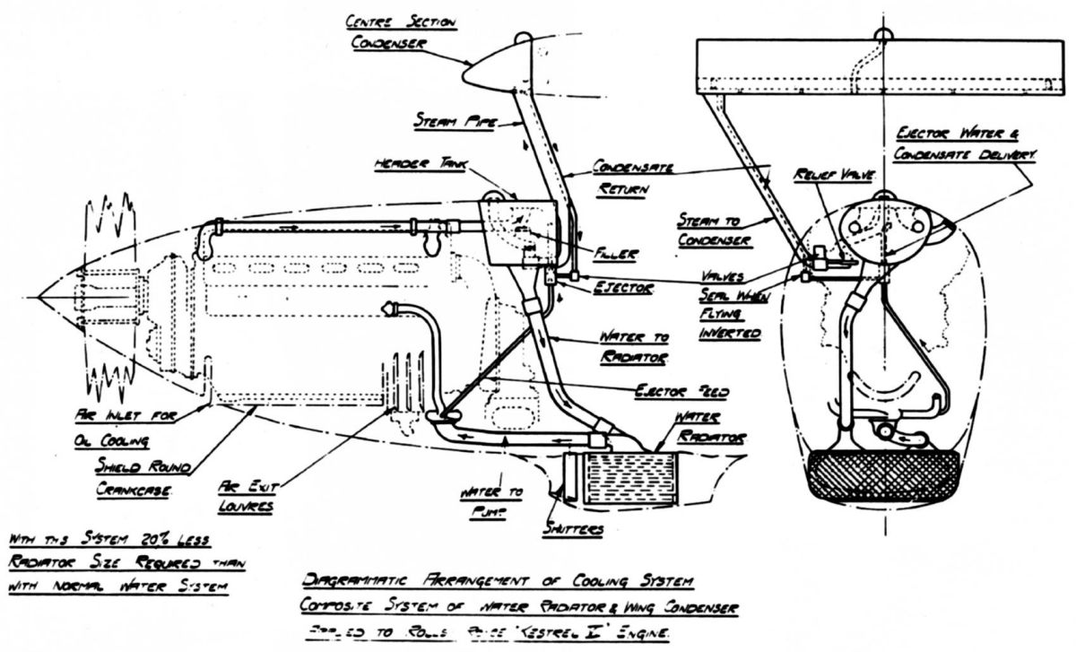
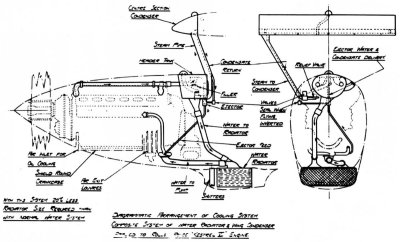
| An early Rolls-Royce Goshawk composite (both vapor and liquid) cooling installation which included a radiator 20% smaller than required with an all water cooling system. The header tank was where vapor was separated, the vapor going to the surface condenser(s) and the liquid to the water radiator. Note that the condensate is returning through a tube in the vapor line, hence it is at the same temperature as the vapor. (From Rolls-Royce Piston Aero Engines – A Designer Remembers, A.A. Rubbra, RRHT Historical Series No. 16, page 56). |
Rolls-Royce Goshawk Engine
In the late 1920s Rolls-Royce performed studies and testing that led them to develop an engine suitable for use with vapor cooling, the Goshawk. This was an evaporative cooled Kestrel, their then current main line liquid-cooled V-12. This was done in response to aircraft designers seeking to reduce the drag of radiators mounted in the slipstream. They believed adequate cooling could be accomplished with surface condensers built into the wings of the aircraft. The Goshawk developed 660 horsepower (490 kW) and only twenty were built, which went to a number of aircraft manufactures for use in prototype airplanes having vapor cooling. The primary drawback was the necessity of a surface condenser, and the piping and pumps required. That said several Goshawk prototype aircraft were built, such as the Supermarine Type 224 and Short Knuckleduster, see Table 1. Rolls-Royce learned much from the project, some of which was incorporated into their later PV-12/Merlin engine design. The coolant circulating through the engine itself was pressurized water, which was then allowed to depressurize and flash into steam at the engine outlet. Flight testing found that pressure upsets in the condenser system would result in loss of suction at the condensate pumps, which would cause local boiling within the pumps with the vapor produced interrupting the flow of coolant back into the engine.[3]
The engine differed from the Kestrel only in details. Water was pumped into the engine at a pressure sufficient to overcome the resistance of the passages and the backpressure of steam formed in the cylinder jackets and heads. Up to 30 % of the coolant volume within the engine could be filled by steam, with the turbulence in the passages keeping the steam dispersed within the coolant. This mixture was then directed to the header tank, where the vapor was separated from the liquid and passed to the condensers. Far more significant were the differences in the radiator installation, a Kestrel needing a conventional radiator and the Goshawk needing none, requiring instead flush condensers which were usually built into the wings. The troubles with the concept were found when the engine was installed in the fast and highly aerobatic High-Speed Fury and Hawker F.7/30. Significantly, the system tended to work poorly or not at all in inverted flight, the steam and water tending to change places.[4] In all the surface condensing installations there had been problems with steam leakage and similar faults, which could likely have been resolved. The installed weight was found to be not very different from that of a water cooling system.
Everyone who has ever constructed one of these systems has done it differently, at least in detail, but the requirements and concept(s) are all the same. The following aircraft have had evaporative cooling systems of one type or another.
Table 1. Pre-WWII Aircraft with Vapor Cooling Systems
| Aircraft | Engine |
Type of Cooling |
|---|
| Albatross L75 | BMW V | ? |
| Antoinette Monoplane | Antoinette V8 | 1 |
| Blackburn F3 K2892 | Goshawk III | 3F |
| Bristol Fighter J6721 | Falcon II | 2, later 3F |
| Bristol 123 | Goshawk III | 2 + 3F |
| Farman-Voisin Biplane | Antoinette V8 | ? |
| Focke-Wulf Fw187 D-CINY | DB 600 | 2 |
| Gloster Gnatsnapper N227 | Kestrel II.S | 2 +3R |
| Gloster TSR.38 S1705 | Goshawk III, VII, VIII | 2 |
| Hawker Audax K1438 | Goshawk I | 3F |
| Hawker Hart K1102 | Kestrel II.S | 2 |
| Hawker Hart K3036 | R-R PV-12 | 2 + 3F |
| Hawker PV-3 1-PV3 | Goshawk III | 2 + 3F |
| Hawker Intermediate Fury G-ABSE | Goshawk III | 2 |
| Hawker Super Fury K3586 | Goshawk III | 2 + 3R |
| Hawker Boiling-tank Hurricane | Merlin | 4 |
| Heinkel He100 D-IDGH | DB 601 ReV | 2 + 3R |
| Heinkel He119 D-AUTE | DB 606 A2 | 2, later 2 + 3R |
| Ilyushin I-21 | AM-34RNF | 2 |
| Kawasaki Ki-61 | Ha-40 | 2 + 3R |
| Kawasaki Ki-64 | Ha-40 | 2 + 3R |
| Messerschmitt Bf209 D-INJR | DB 601 ReV | 4 |
| Short Knuckleduster K3574 | Goshawk | 3F |
| Supermarine 224 K2890 | Goshawk II | 2 |
| Supermarine Spitfire Type 323 K9834/N17 | Merlin II Special | 4 |
| Westland Pterodactyl K2770 | Goshawk II, III | 3F ? |
| |
| 1 = Rows of Tubes |
| 2 = Surface Condensers in wing |
| 3F = Honeycomb condenser, fixed |
| 3R = Honeycomb condenser, retractable |
| 4 = Engine coolant vapor vented, bypassed condensers |
| 2 + 3F or 3R was called Composite Cooling |
The later Rolls-Royce Merlin uses a water/glycol mixture for cooling; however the thermodynamic properties of the water component dominate. In this manner Rolls allowed a considerable amount of boiling within the cylinder heads which results in comparatively large amounts of vapor in the exiting coolant. A key to handling this vapor is the manner in which they incorporated the “header” tank (expansion tank) which is directly connected to the front of the engine. This tank incorporates integral vapor separators to insure that only liquid is actually circulated through the cooling system, the vapor being condensed within the header tank and returned with the coolant to the radiator for cooling.
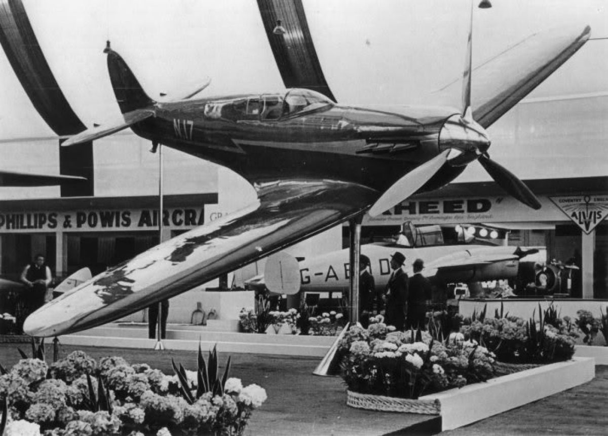
Speed Spitfire, Supermarine Type 323
Soon after the prototype Spitfire, K5054, was flying in 1937 interest was expressed to have the type break the current FAI speed record of 352 mph held by the Howard Hughes H-1. Rolls-Royce began work on a ‘Sprint’ Merlin able to deliver over 2,000 horsepower[5] while Supermarine took the 48th Spitfire airframe, K9834, and revised it for speed. This included shortening the wings, flush riveting and installation of a larger, but streamlined, radiator to provide the increased cooling. In June 1938 the Heinkel He 100 set a new 100 km closed course record at 394 mph, which was close to the expected top speed of the ‘Speed Spitfire’. The aircraft was flown in this configuration and achieved a top speed of 408 mph at 3,000 feet, which would give an estimated speed at sea level of about 400 mph. This was deemed insufficient to assure success and the decision was made to remove the radiator and fit a ‘boiling tank’ in place of the upper fuel tank. This installation would use recirculating water to cool the engine with the hot fluid returning to the boiling tank for condensation, with the remaining vapor ejected via a vent beneath the aircraft.
Concurrently in Germany the speed record had been broken by both Heinkel (463 mph) and Messerschmitt (469 mph), speeds well beyond the capability of the Spitfire. Work on K9834 continued with the removal of the radiator and installation of the boiling tank that June. It was then decided to place the aircraft on exhibit at the International Aeronautical Salon in Brussels that July, though the boiling tank had not yet been fitted. Following the show the aircraft was returned and the modifications continued, though at a low priority. It was April 1940 before it was ready for flight, and then a rupture of the boiling tank prior to flight ended the program. Because of the critical need for Spitfires for the war effort Supermarine the boiling tank was removed and the aircraft returned to an operational configuration as a high speed photographic reconnaissance aircraft. It reverted to a standard Merlin XII, 3-blade propeller and radiator, but with only 60 gallons of fuel. It retained its blue and silver high speed finish, though with RAF markings applied.
 |
 |
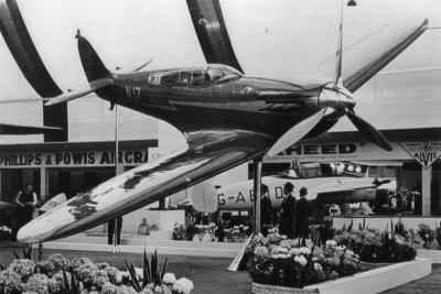
| The Supermarine High Speed Spitfire, K9834/N17, without a radiator while on display at the July 1939 Second International Aeronautical Exhibition at the Palais de Centenaire, Brussels. Modifications for installation of the boiling tank cooling system were underway at the time, however were not completed until April 1940. |
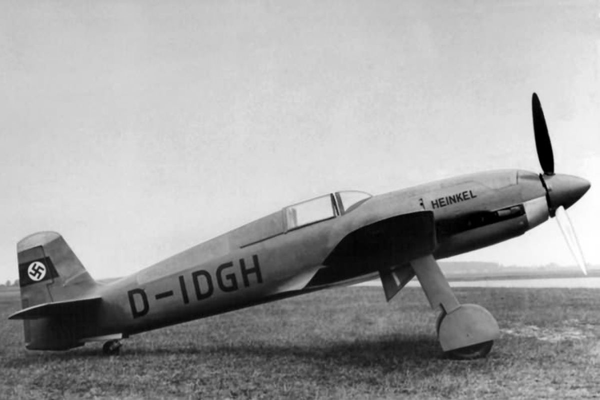
Heinkel He 100 V8 featured steam-condensing radiators built into the wing surfaces as a way to reduce cooling drag on the airplane. The engine was the Daimler-Benz DB 601 ReV (Rekordmotor #5). From the look of the exhaust soot is appears that they did not derich the fuel mixture to best-power when running water-methanol (ADI) at high power. The oil was cooled by an ethyl-alcohol boiler located behind the canopy. |
Heinkel He 100: 3 km World Record Holder, March 30, 1939
This high-speed fighter was built by Germany’s Heinkel, with its first flight occurring January 22, 1938. Only about 25 were built, including prototypes. Germany’s Ernest Udet flew prototype He 100 V2 to a new world record over a 100 km closed course of 634.320 km/h (394.148 mph) in June 1938. The He 100 V4 prototype was built with clipped wings and fitted with a special Daimler-Benz DB 601 ReII[6] engine, rated for 1,776 bhp (1324 kW) at 3,000 rpm, up from the 2,200 rpm rating of the standard DB 601 A, but it only had a service life of 30 minutes. This aircraft was lost when the landing gear would not properly function and the pilot parachuted.
Another of the prototypes He 100 V8 was then modified to the V4 configuration, but completed with the up-rated DB 601 ReV engine, 2,770 PS[7]. This engine featured a methanol-water injection system to cool the supercharged air to the cylinders. This allowed operation at higher manifold pressures. It was with this aircraft that Hans Dieterie established a new FAI world 3 km course record of 746.606 km/h (463.92 mph) on March 30, 1939.
All of the He 100s featured pressurized water to cool the engine with a steam separator directing the steam to surface radiators built into the wings, where it was condensed and returned to the engine cooling circuit. As such the system was intended for continuous service, and very little make-up water was required to sustain operation. The aircraft had a similar system for cooling the oil, although it used ethyl-alcohol as the working fluid. This was necessary as the boiling point of water is too high to get the needed oil temperature entering the engine. In this case the oil circulated through a heat exchanger that functioned as an ethyl-alcohol boiler, with the resulting vapor being condensed in a surface radiator built into the turtle-deck behind the cockpit. These systems used numerous electrically powered scavenge pumps to collect the condensate and return it to the system header tank(s).
Messerschmitt Bf 209/Bf 109R: 3 km World Record Holder, April 26, 1939
This aircraft was built solely for the purpose of breaking the FAI World Speed Record. The first of three aircraft, the Bf 209 V1 (D-INJR), flew in July 1938. The second, Bf 209 V2 was lost during a forced landing on April 4, 1939, when the oil cooling system suddenly failed on approach, causing the engine to seize. Pilot Flugkapitän Fritz Wendel survived the crash with only minor injuries. The third prototype, Bf 209 V3, had been intended to accomplish the record flight however it had not been completed at this time and Willy Messerschmitt was encouraged by the Luftwaffe RLM to best the Heinkel record, set only six days before, as soon as possible. They were having a difficult time explaining how a German aircraft that was not in the Luftwaffe could be faster than the lauded Messerschmitt Bf 109. At that point Bf 209 V1 was quickly refurbished with additional tankage and the revised wing, and then fitted with the special DB 601 ARJ (V10)[8], to become the record breaker. On April 26, 1939 test pilot Fritz Wendel flew it over the 3 km course to a new record of 755.138 km/h (469.224 mph), eclipsing the Heinkel He 100 record set the previous month. For propaganda purposes the German Luftwaffe released the news that the new record was set by the Messerschmitt Bf 109R, hoping to further enhance the mystique of their Bf 109 fighter then in wide use. Heinkel immediately asked the RLM for permission to attempt to top the Messerschmitt record, and was denied. Also known as the Me 209/Me 109R, the record breaking Bf 209 V1 (D-INJR) airframe still exists and is on display at the Polish Aviation Museum in Kraków, Poland, without its engine, which was returned to Daimler-Benz following the record flight.
Like the Heinkel He 100 the Bf 209 V1, V2 and V3 were fitted with a special wing containing surface radiators designed to condense the steam coming from the separators. This system presented immense difficulties as the wing skin radiators encountered considerable thermal stresses and deformations, primarily due to being unable to sustain the vacuum created by the condensing steam[9], while they did not function very effectively as condensers.[10] During the flight testing of V2, with an improved wing and condensers, it was found that makeup water of 4 – 7 liters (1.05 – 1.85 US Gallons) per minute was required.[11] As a result it was decided to dispense with the recovery of condensed cooling water and to completely replace the lost water, some 9 – 10 liters (2.4 – 2.6 US Gallons) per minute. Water reservoir capacity was then increased to 450 liters (119 US Gallons) to provide sufficient water during the record flight.
The aircraft also had 500 liters (132 gallons) of special fuel. This was the German standard C2 fuel, with a performance rating of 100/130, but doped with a large amount of alcohol. This tank was located in front of the aft placed cockpit, as well as a 50 liter (13.2 US Gallons) tank directly behind the engine for Water-Methanol anti-detonate injection fluid, and a 220 liter (58.1 US gallons) tank of water for the cooling system, increased to 450 liters for the record flight.
Oil cooling on the Bf 209 V1 was accomplished using surface cooling with a ring radiator positioned directly behind the propeller spinner.
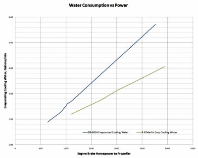
For the record run the DB 601 ReV (V10) was installed, rated for 2,770 PS (2,732 BHP) or 2,035 kW, for the five minutes of the record run. To achieve this power, and the required boost of 2.1 bar abs (62 inHgA), the engine was run at 3100 rpm. Rated speed for the DB 601 A from which the DB 601 Rekordmoters were constructed was 2,400 rpm, with 1.4 ata (41.9 inHgA) boost. Coolant temperatures were allowed to go to 120 °C (248 °F), which means that the coolant pressure was at least 2 atm, or 30 psia. This is the same rating as the engine used in the He 100 V8 when it established the earlier record. The DB 601 ReV engine used a 1.55:1 propeller reduction gear, the same as used on the DB 601 A series engines, as well as the same step-up gear ratio for the supercharger, the standard 10.38:1 although it appears that the fluid drive unit was replaced with a mechanical clutch. A performance curve for the DB 601 ReV engine, dated June 27, 1939 shows that at 3,100 rpm the engine produced approximately 2.5 ata (74.8 inHgA) and 2,500 PS (2,466 BHP) at sea level.[12] There is a discrepancy between the power of the DB 601 ReV (2,770 PS, 2.1 bar abs [62.0 inHgA]) Daimler-Benz specification and its “wide open throttle” performance curve (2,500 PS, 2.5 ata [74.8 inHgA]), both at 3,100 RPM[13]. Since the performance curve is dated after the Record flight it is likely to be the more appropriate value for the power delivered at the time of the flight. Figure 1 shows that at 2,770 PS the engine would have been evaporating 5.72 gallons per minute (21.6 liters/m) of cooling water, it was a good thing that it did not take long to travel the three kilometers.
 |
 |
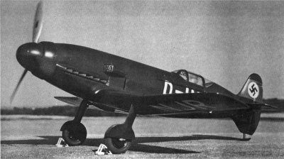
| The Messerschmitt Bf 209 V1 also featured steam condensing radiators built into the wing surfaces as a way to reduce cooling drag on the airplane, however the problems with them caused Messerschmitt to bypass the condensers and simply vent the steam coming from the cooling system. The engine was the Daimler- Benz DB 601 ReV(V10) a “Rekordmotor #5”. Note the air-cooled annular oil cooler directly behind the propeller spinner. (Scale model and photograph by Günter Sengfelder) |
Figure 1. Accurate information on the quantity of heat into the coolant is difficult to obtain. The above data for the DB 601A was obtained from wartime testing done at Wright Field, but only covered the range up to normal Takeoff power, 1,100 BHP. The Merlin data comes from a wartime NACA report that tested up to 2,000 BHP. For Record and Racing purposes these engines need to operate at near 3,000 BHP. Significantly, the available data plots in a smooth linear manner, suggesting that extrapolation to higher power is appropriate. The available Messerschmitt information that 2.5 gpm (9.5 liters/min) of water was used when running the DB 601 ReV engine at 2,732 BHP (2,770 PS) is likely the average amount used for the total flight, this same issue applies to the Reno racers with Open Cycle cooling. Note that when ADI is used as the cooling fluid the flow rates shown increase by 27.6%. |
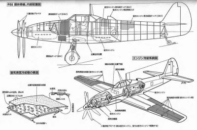 |
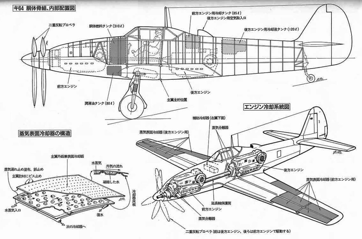
| Kawasaki K-64 Fighter featured vapor cooling of its two Kawasaki Ha-40 engines (license-built DB 601). This drawing shows the location of the radiator/condenser panels as well as the locations of the water tanks. The scoop behind the cockpit is the air intake for the aft engine. |
Kawasaki Ki-64 Twin-Engine Fighter
Japanese interest in vapor cooling of an aircraft engine was probably stimulated by their acquisition of three Heinkel He 100 aircraft with such systems in 1940. Kawasaki configured a prototype of their Ki-61 (Allied code name Tony fighter) with such a system in October 1942 and made 35 flights through the end of 1943, when its’ testing was finished.[14] That aircraft was powered by a Japanese built copy of the Daimler-Benz DB 601 A, so it provided a viable opportunity for incorporating a similar vapor cooling system. Takeo Doi, chief designer for Kawasaki, reported that the vapor cooling system increased the top speed of the Tony from 380 mph to 405 mph (608 – 648 km/h). Only one such aircraft was built, and it was subsequently destroyed.
With the experience of the He 100 and Ki-61 Kawasaki proceeded with the design of the Ki-64 (Allied code name Rob), with a maximum speed of 429 mph at 16,000 feet (690 km/h at 5,000 meters). It featured two Kawasaki Ha-40 engines, one in front and the other behind the pilot, with the drive-shaft from the aft engine passing through the cockpit in a similar manner as in the Bell P-39. Contra-rotating propellers in the nose were driven independently and either engine could be shutdown in flight and its three-bladed propeller feathered. The primary feature of the aircraft was its vapor cooling with radiators/condensers built into the wings. The right wing system connected to the aft engine and the left wing supporting the front engine. Each engine had two steam separators, four upper wing condenser panels, four lower wing skin panels, and two sections of hollow flap used as condensers. Each engine had an 18 gallon water tank in the leading edge of the wing near the fuselage, as well as a make-up tank located in the aft end of the fuselage. The Ki-64 first flew in December 1943. During its fifth flight the rear engine caught fire, leading to an emergency landing in which it was damaged. The airframe survived the war and parts of the unique cooling system were taken to Wright Field for study.[15]
The Japanese were not entirely satisfied with the vapor phase cooler, but were enthusiastic about its possibilities as it weighed no more than a conventional radiator system. There was a shortage of needed materials and they never completed the development of the airplane. Only five flights were made as priorities shifted during the last year of the war.
As there are very few details about any of these cooling systems it is indeed fortunate that the Kawasaki designers provided details on the system in the Ki-61. Since the same engines were used in the Ki-64 the parameters should have been about the same.
Water at the outlet of the engine was at 4.2 atm, 110 °C (62 psia, 230 °F), and flowed directly to the vapor separators. There it entered tangentially and because the vapor discharge was vented though the condensers to atmosphere, the pressure was dropped to about 1.1 atm (16.2 psia), and as a result reduced the boiling point while vaporizing about 1.3 % of the water.
The Ha-40 engine cooling load was about 96 kcal/sec (381 BTU/sec, or 537 hp) and the coolant flow about 14 liters/sec (222 gpm). This resulted in about 0.18 liters/sec (2.85 gpm) vaporizing.
The water is cooled by the latent heat of vaporization going into the vapor, resulting in a decrease in water temperature to 104 °C, and a pressure of 1.5 atm (22 psia) into the coolant pump. This pressure rise was accomplished by recovering the velocity energy in the water leaving the separator in a specially designed section of diffuser piping.
When water vaporizes it expands about 1,700 times, resulting in a high-speed flow of about 80 m/sec (263 ft/sec) to the wing condenser panels. For the Ki-64 130 square feet of condenser/radiator surface was provided for each engine.
During times of insufficient cooling, ground operation or climbing, the vapor pressure would reach about 1.3 atm. A pressure relief valve was fitted to only allow a maximum of 1.1 atm (16.2 psia), though this resulted in quantities of vapor being lost from the system and increased the amount of makeup water required.
Condensate coming from the condensers was pumped back to the reservoir using venturi pumps, as they did not have reliable electric pumps available. The venturi pumps were powered by high pressure water coming from the coolant pump, prior to being reheated in the engine.
Kawasaki argued that since the amount of vapor in the condenser portion was small compared to the circulating water, it was felt that it was not vital if the condenser panels were punctured by gunfire.
The Authors
Daniel D. Whitney is a retired Mechanical and Nuclear Engineer, graduating from Oregon State University in 1965 with a BSME. He then served in the USAF as Chief of Aircraft Maintenance for a Wing of C-130E aircraft. Following discharge he enrolled at Stanford University and earned his Master’s degree in Nuclear Engineering in 1970. He then worked in the electric utility industry, where he provided engineering support for a large Pressurized Water reactor. He subsequently designed co-generation gas turbine power plants and their associated heat recovery steam cycles. Following retirement he focused on his first love, WWII era V-12 aircraft engines, in particular, the Allison V-1710. He is the author of Vee’s For Victory! The Story of the Allison V-1710, as well as a number of magazine and journal articles relative to the technologies and history of these fine engines and the aircraft they power. In retirement he has provided a number Reno race teams with technical support, as well as working with engine builders to keep these marvelous engines going. This has included designing new internal parts for engines and gaining FAA approval for their use. He is a charter member, and Vice President, of the Aircraft Engine Historical Society, and has been a life member of the Rolls-Royce Heritage Trust for over 30 years.
Peter V. Law earned a degree in Mechanical Engineering and Thermodynamics from Stanford University in 1958, followed by a Master of Science in Aerospace Engineering from University of Southern California in 1965. His professional career started in January 1959 as a Thermodynamics Engineer at Lockheed in Burbank, where he worked over 42 years. He was transferred to the Lockheed Skunk Works® in July 1961, and from 1980 on he was the Manager of the Thermodynamics Department at the Skunk Works®. He has been involved in many unique programs, including the F-104, A-12, YF-12A, SR-71, M-21, D-21, U-2, YF-22, JSF(X-35), and many other still classified projects. Several of these advanced jet aircraft included evaporative cooling systems which he engineered. Starting in 1964 he began working to improve the capabilities of Unlimited Air Racers, and since 1970 he provided similar support for Unlimited Hydroplane racing where he helped developed nitrous oxide power boosting systems for drag boats as well as Bonneville racing cars. He has done much more than design evaporative cooling systems, specifically for many years he provided the carburetors and water/ADI regulators needed for operating race engines at high power. Pete is a charter member of the Aircraft Engine Historical Society, and has been a life member of the Rolls-Royce Heritage Trust since 2006. In 2013 Pete gave a presentation to the Heritage Trust-Darby, on the Pratt & Whitney J58, the engine powering the SR-71. Pete continues working as a consultant on advanced Aerospace systems, while he and his wife Joanne enjoy traveling and the company of their many friends.
David Birch – Pete and Dan want to thank David Birch, RRHT Darby Branch Editor, for motivating the creation of this article. He has also provided guidance and material, particularly as related to the early efforts to utilize vapor cooling.
Notes
[1] In the Metric system thermal energy is the calorie, the amount of heat needed to change the temperature of one gram of water one Centigrade degree. A kcal is 1,000 calories, the quantity of heat needed to change the temperature of one kilogram of water one degree Centigrade.
[2] From a practical standpoint all of this can be resolved so that for each 100 horsepower (74.6 kW) of heat to be rejected 0.72 US gallons per minute (2.73 liters/min) of 50:50 ADI fluid is consumed/evaporated.
[3] Development of Aircraft Engines & Development of Aircraft Fuels, Robert Schlaifer & S.D. Heron, 1950, page 234.
[4] Rolls-Royce Aero Engines, Bill Gunston, 1989, page 49.
[5] A special fuel mixture, gasoline with benzol and methanol plus tetraethyl lead. allowed running at 3,200 rpm and 28 pounds boost (87 inHgA, 2.9 atm). The engine developed 2,100 horsepower (1,567 kW) during its 15-minute type test.
[6] These engines were based upon the DB 601A, which was rated at 2,500 rpm and 1.45 ata (43.4 inHgA) for one minute, delivering 1175 PS (1,159 BHP). The German system of identifying engines is somewhat unique. “Dashes” are not used between terms, i.e., DB 601 A is not DB-601-A. Daimler-Benz built a series of “Rekordmotors” over a four year period. These were identified as DB 601 ReI, ReII, ReIII, ReIV and ReV, Roman Numerals being used to distinguish between models. The “V” number is “versuchs” indicating “prototype”. The ReV engine installed in the Bf 209 V1 was V10, indicating it was the tenth prototype Rekordmotor.
[7] PS is “Pferdestärke” German for metric Horsepower, 735.499 watt/PS. English Break Horsepower is 745.699 watts/HP, thus 1 PS = 0.986 BHP. Some references say the engine used produced some 600 HP less than the engine used in Bf 209 V1. According to Daimler-Benz the two aircraft used the same DB 601 ReV model engine rated at 2,770 PS.
[8] Also known as the DB 601 ReV, 5th model of the family of Record Breaking engines. The V10 was the tenth engine in this series.
[9] Flugmotoren und Strahltriebwerke, Vol 2, Gersdorff & Grasmann, 1985, p. 102.
[10] Messerschmitt Me 209, FliegerWeb.com
[11] Bf 209 V1 Report of Test flight Nr. 230, March 9, 1939. Air Documents Division, Microfilm R2763, Frame 1000 at NASM.
[12] Einbau-Mappe (Installation Manual) for the Mercedes-Benz Flugmotor series DB 601 Record Sea-Level Flights, Air Documents Division, T-2, AMC, Wright Field, Microfilm R2487, F939, July 8, 1939.
[13] Note: 1 bar = 0.987 ata, a 1.3% difference.
[14] Japanese Ki-64 Single Fighter with Two Engines in Tandem and Vapor-Phase Cooling, Air Technical Intelligence Review No. F-IR-100-RE, August 1946.
[15] Ibid.