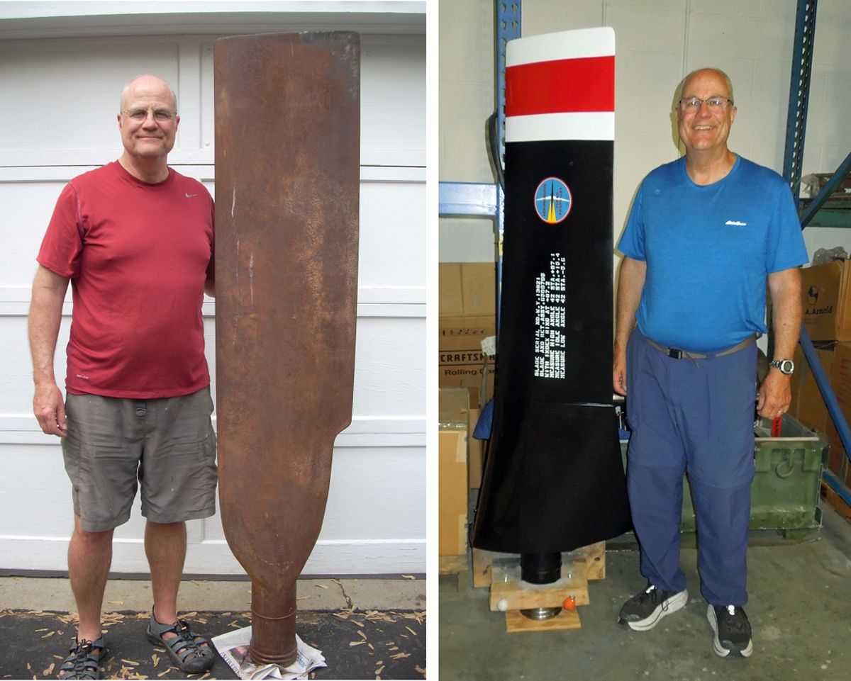
Model 248 Blade Before and After
Restoring a Hollow Steel Turbopropeller Blade
by Tom Fey
Published 20 Aug 2023
Model 248 Blade Before and After |
The Rolls-Royce Heritage Trust Allison Branch in Indianapolis, Indiana is tasked with researching, preserving, educating, and displaying products generated by Allison, Rolls-Royce, and their legacy companies. Aeroproducts was a company under the Allison Division of General Motors whose primary business was the manufacture of hollow steel propellers of a unique hydraulic design from the 1940s through the late 1970s. Aeroproducts made propellers for both commercial and military use on piston (North American P-51 &amo;P-82,Bell P-39 & P-63, Grumman F8F, Douglas AD series) and turbopropeller (Lockheed L-188, Convair 580, Grumman E-2A & C-2) driven aircraft. In 2021 the Trust happened across a model “248” (A6441FN-248) propeller blade used on the early Grumman E-2A/C-2A naval aircraft being offered on eBay, I made the Trust an offer that if they bought the blade, I would restore it for them. They did, so I did. |
 |
 |
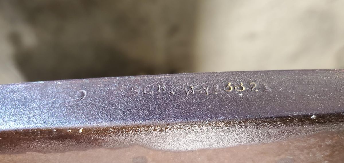 |
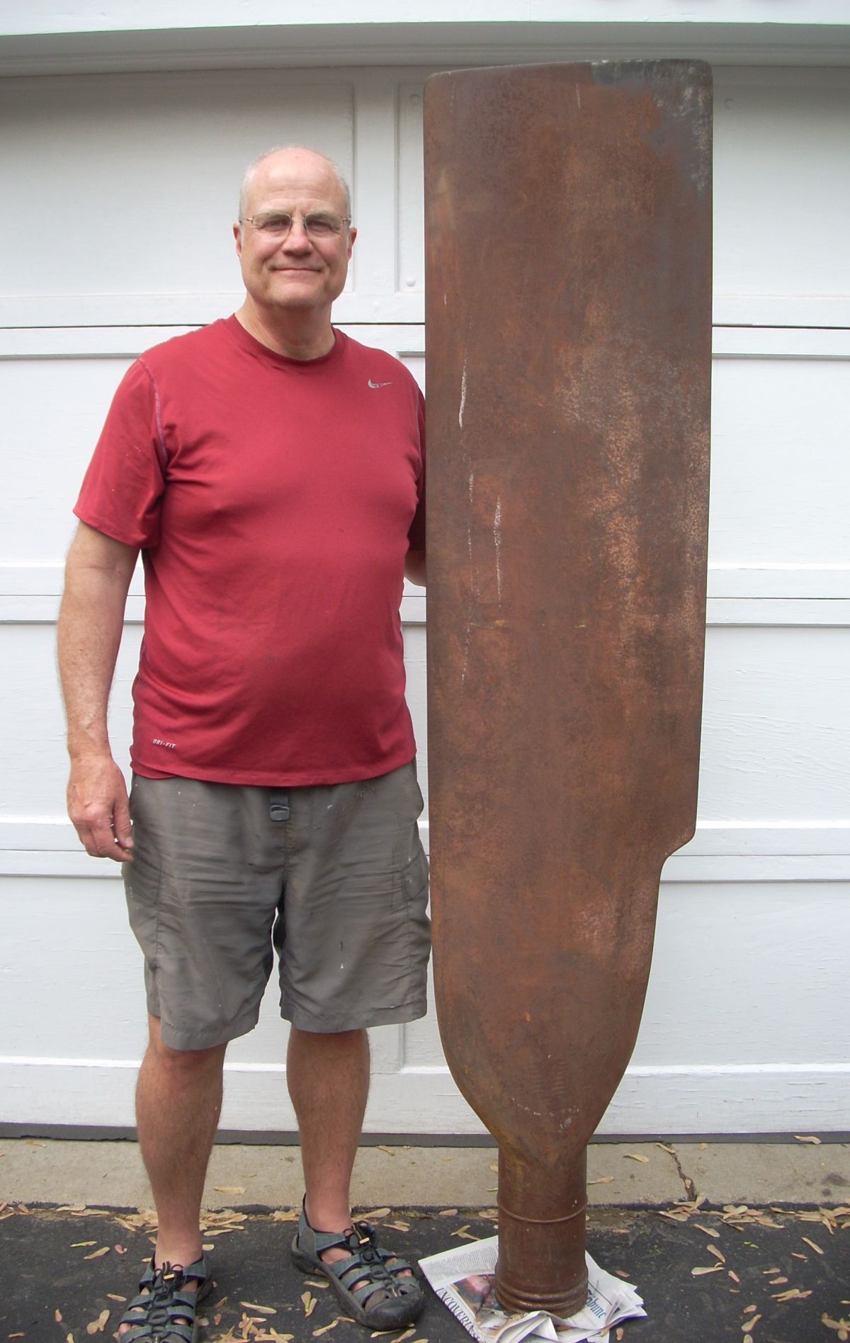
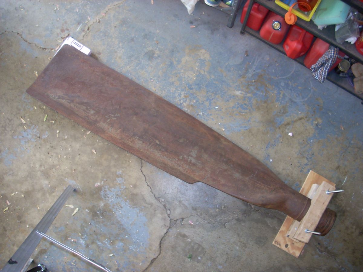
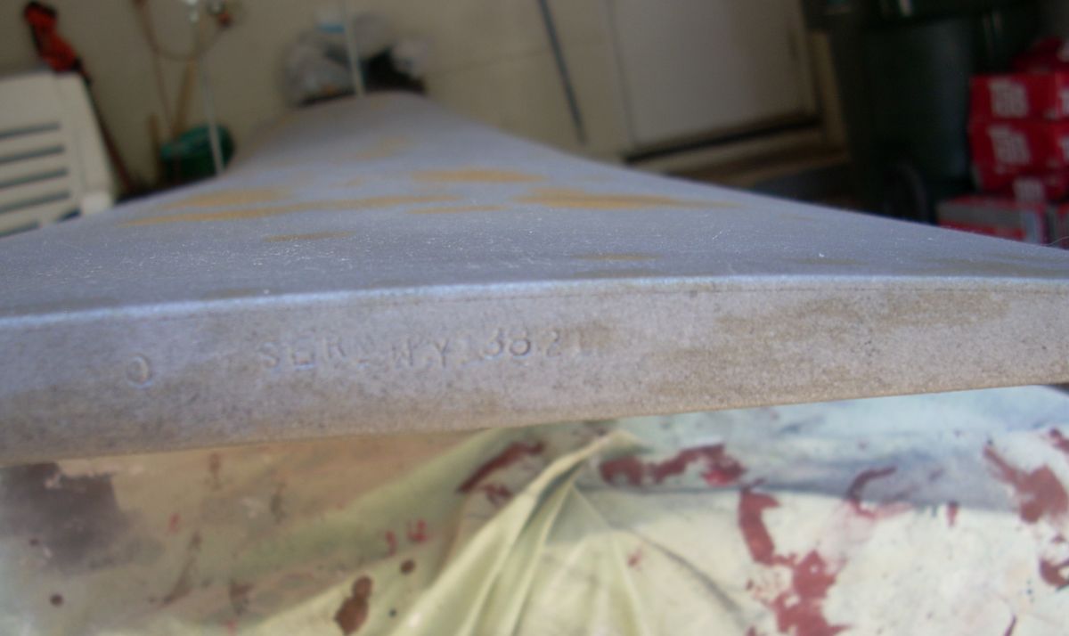
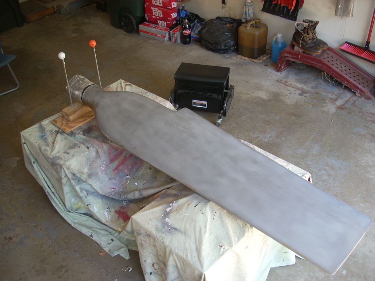
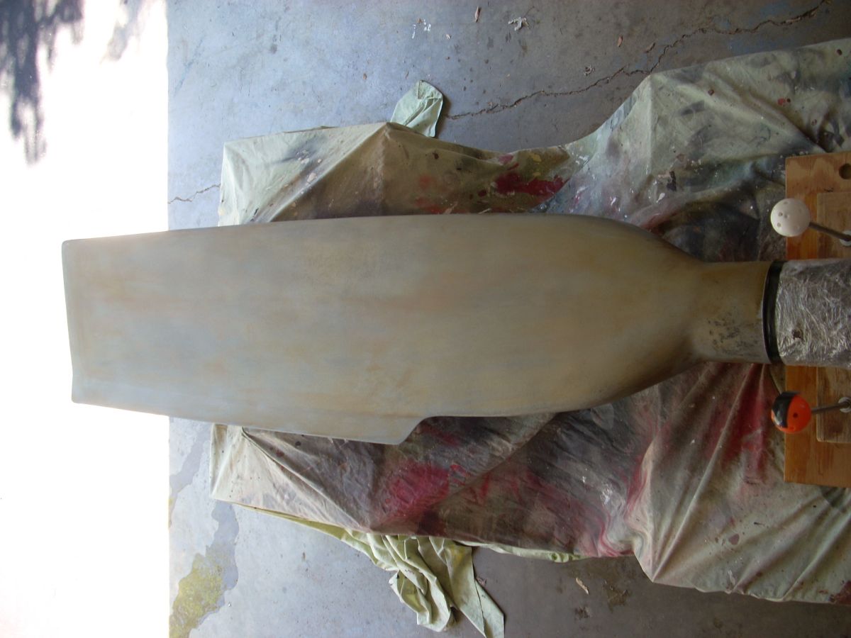
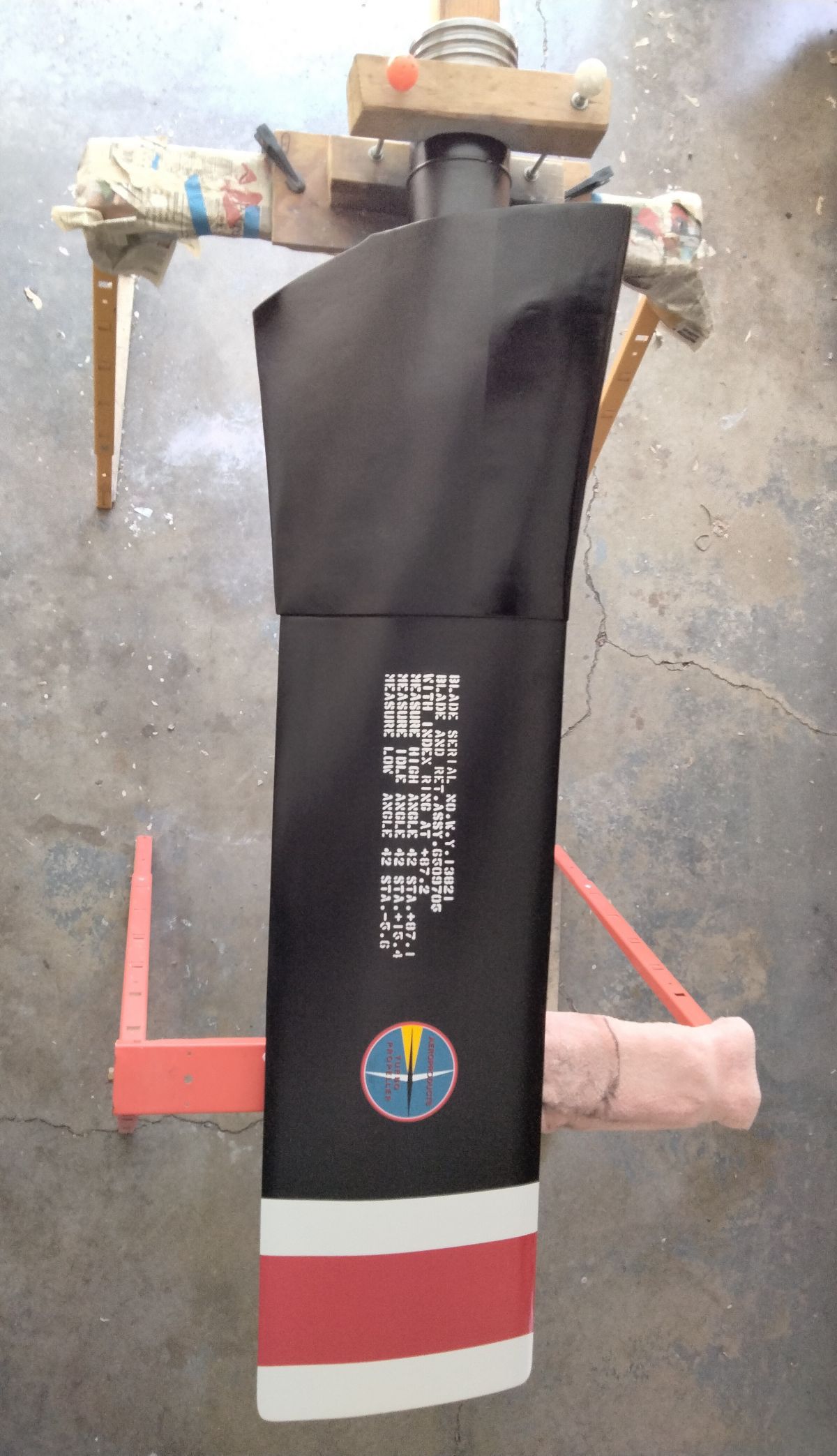
| Pic 1: The 248 blade is 76 inches tall and weighs approx. 110 pounds. Camber (front) face is shown. | Pic 2: Thrust (aft) face of the 248 blade showing the asymmetric “camber sheet extension” on the bladetrailing edge. | Pic 3: Serial number W.Y. 13821 is stamped in the blade tip . Original blade drawing number is F40K-198-18M2. |
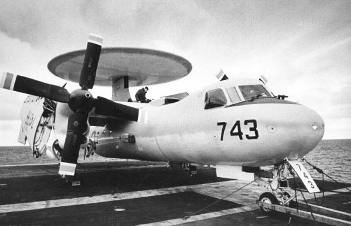 |
| Pic 4: Grumman E-2A with Aeroproducts A6441FN-248 propeller. |
The first fifty-nine Grumman E-2A Airborne Early Warning aircraft used the Aeroproducts 248 propeller driven by the Allison T56 turboprop engine. (Pic 4) Only two hundred fifty 248 propellers were manufactured. The E-2A had a number of issues in its adolescence, primarily dealing with its AEW electronics package, which took some years, groundings, and a Congressional inquiry to rectify. The improved models of the E-2 flew with the ubiquitous Hamilton Standard 54H60 turbopropeller system found on the T56-powered Lockheed P-3 and C-130B to C-130H aircraft.
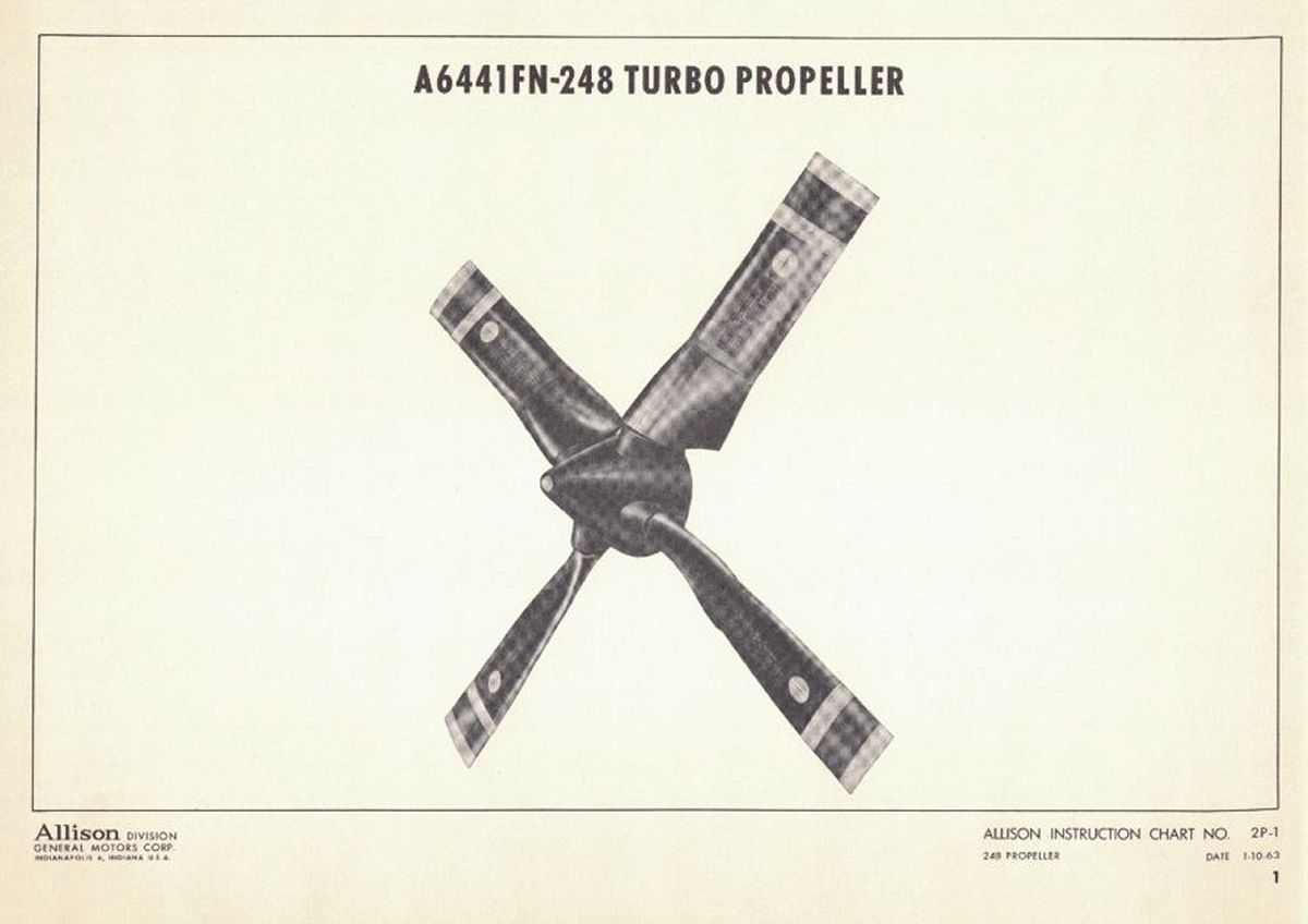
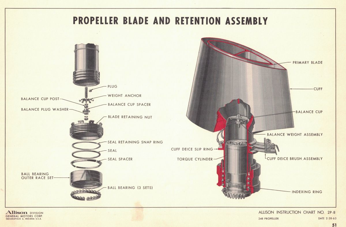
The T56-A-8/8A produced 3,755 horsepower at takeoff power in the E-2A (up to 5,100 horsepower in later models), which required a four-bladed propeller of 13.5 feet in diameter, 16.5 inches in chord, an Activity Factor of 157, weighed 1,018 pounds complete on the wing, and was governed to spin at a constant 1,106 rpm. (Pic 5) The hollow steel blade was constructed from two pieces of forged and machined 4350 steel that were furnace-brazed together at 2,200 °F then roll-welded together on the leading and trailing edges. (Pic 6) The design utilized a single longitudinal spar down the center of the blade and a flap-like extension of the camber (front) sheet termed a “camber sheet extension”. This 2.5-inch chord extension was angled at approx. 15 degrees like a flap to optimize thrust at low airspeeds such as takeoff and economy cruise. The finished blade had their integral bearing races flame-hardened and match-ground to specific bearing components, the exterior was plated with zinc, the cuff was molded in place, and rustproofed with several coats of specialized paints. (Pic 7) The hollow interior of the blade was rustproofed, the cavity filled with dry nitrogen, and hermetically sealed. (Pic 8)
 |
 |
 |
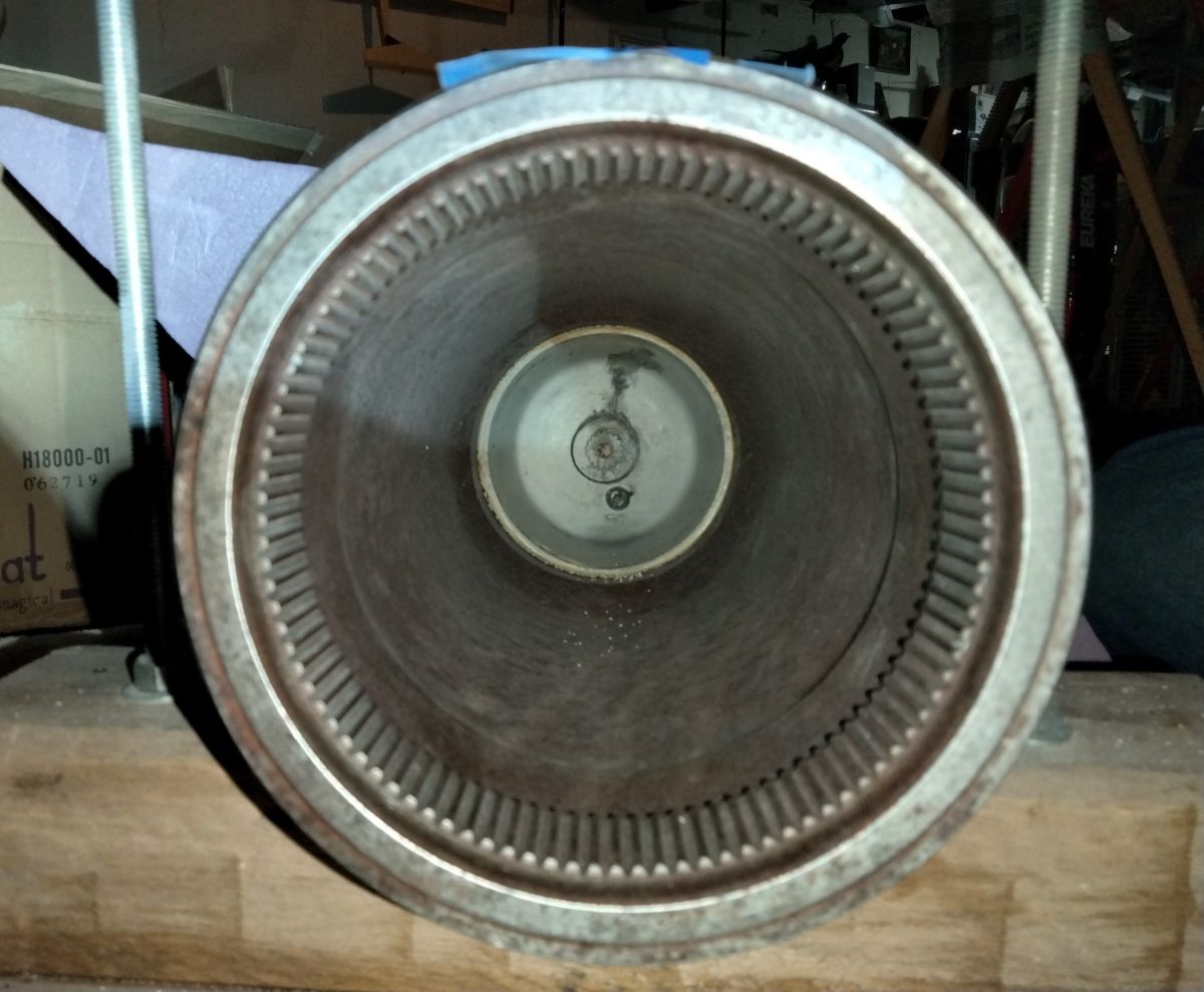 |
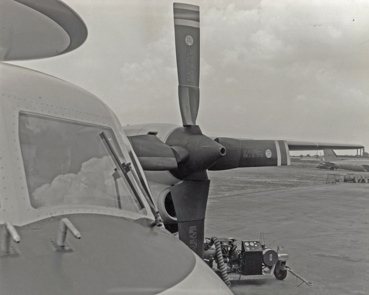
| Pic 5: Photograph from the Aeroproducts Instruction Handbook showing the Aeroproducts A6441FN-248 turbopropeller of 13.5 feet in diameter. | Pic 6: The braze seam between the camber and thrust member of the two-piece blade can be seen along the camber face running upwards along the leading edge and curving left over the shank. | Pic 7: The single span-wise spar can be seen inside the otherwise hollow blade. The shank is hollow to accept the hydraulic torque units that change the pitch of the blades. | Pic 8: Looking up the bore of the propeller shank. The inner bore has 100 indexing teeth to provide adjustment to the torque units. |
The 248 blade acquired for restoration had been refurbished and yellow-tagged in 1975, but sat in a California shed for 46 years. The blade was missing the molded polyurethane cuff that faired the inner 24 inches of the blade root to reduce drag, improve engine air inflow, and provide electric anti-icing. The cuffless blade stands 76 inches tall and weighs +/- 110 pounds. Despite the zinc plating and 5 coats of rustproofing paint applied in August 1975, significant corrosion and pitting was found on all surfaces of the blade. (Pic 9)
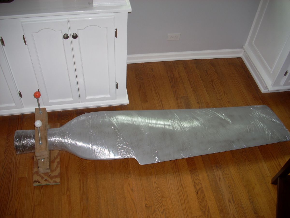
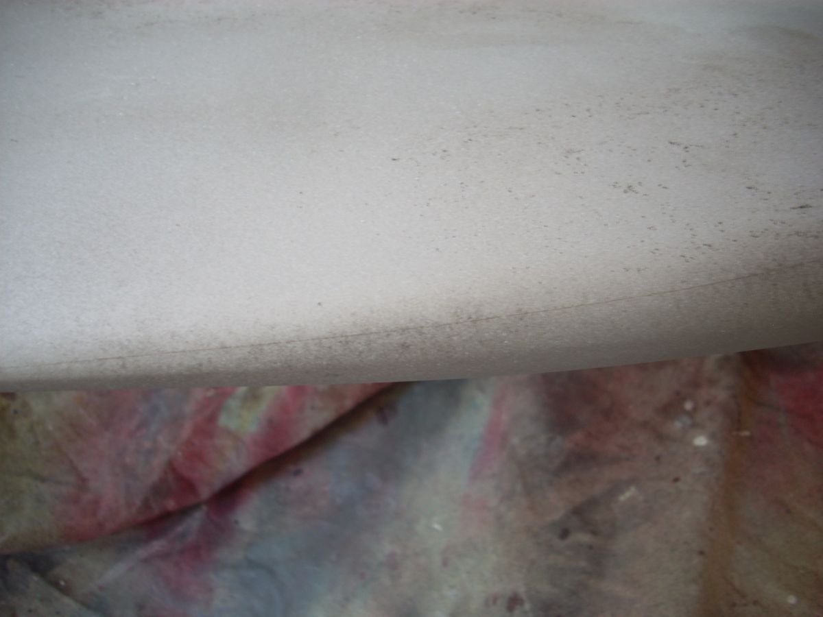
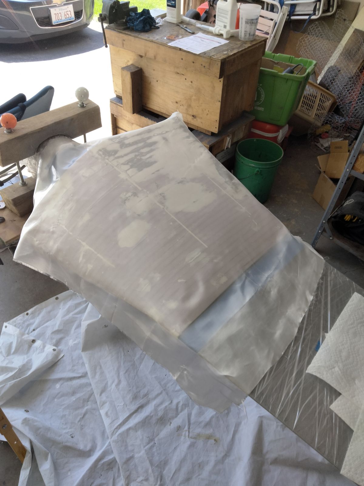
A true technical restoration of the blade using approved materials and methods and was beyond practical and economic reality, so liberties could be taken with this forever-static restoration. The hardened shank of the blade where the bearing races reside was sand blasted with corn cob media, but this media proved inadequate for cleaning the blade proper. Reluctantly, a typical 60 grit media was used to remove the corrosion but thankfully caused minimal erosion of the zinc plating. All blasting was done outside, the blade quickly vacuumed clean, placed inside in low humidity environment, and wrapped in plastic wrap until surface preparation could be done. The pitting is the dark speckles in Pics 10 and 11.
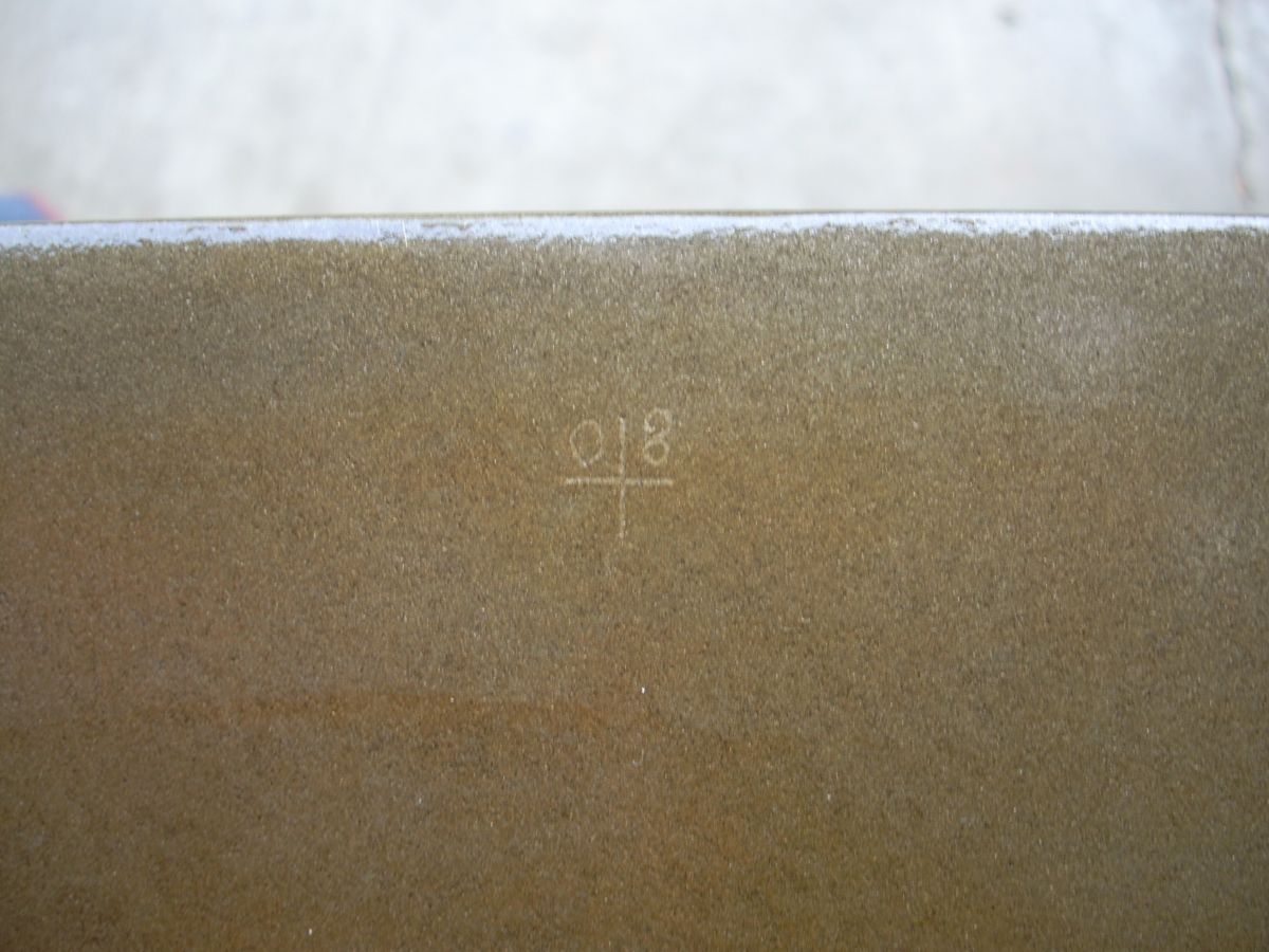
The cleaned blade revealed an etched cross with “80” one inch from the tip on the aft face of the blade indicating the 80-inch station, the serial number punched into the tip, and the seams where the machined 0.09-inch-thick camber sheet (front face) was brazed to the larger thrust member. (Pics 12 - 15)
 |
 |
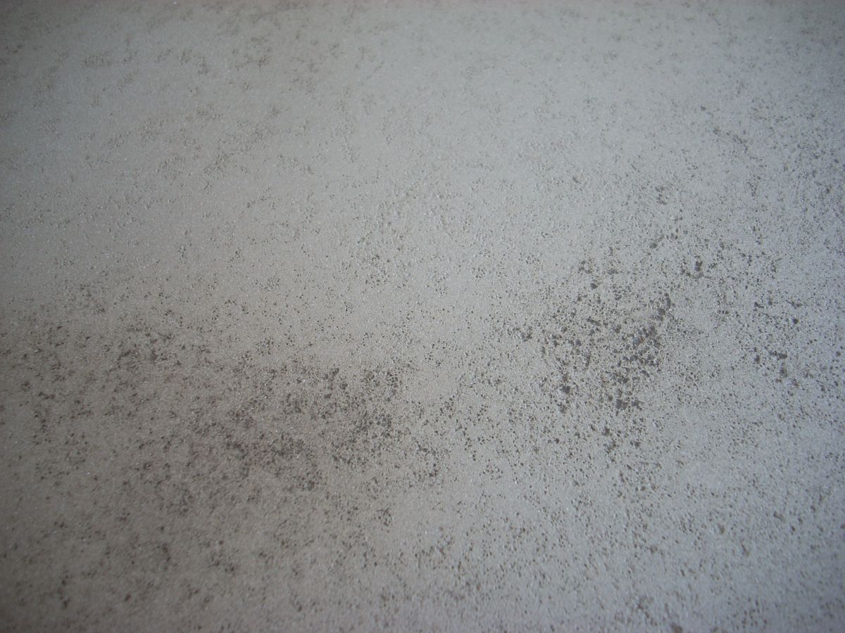 |
| Pic 9: Extensive pitting of the shank exterior is apparent. | Pic 10: The freshly sandblasted and plastic-wrapped 248 blade awaiting less humid conditions for further restoration work. Corrosion pitting is visible as the diffuse black areas all over the blade. | Pic 11: Close-up of the pitting on the surface of the blade. |
 |
 |
 |
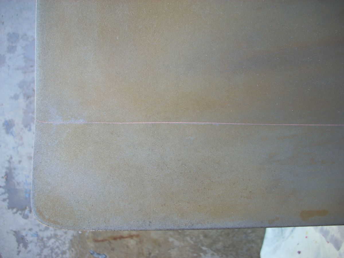 |
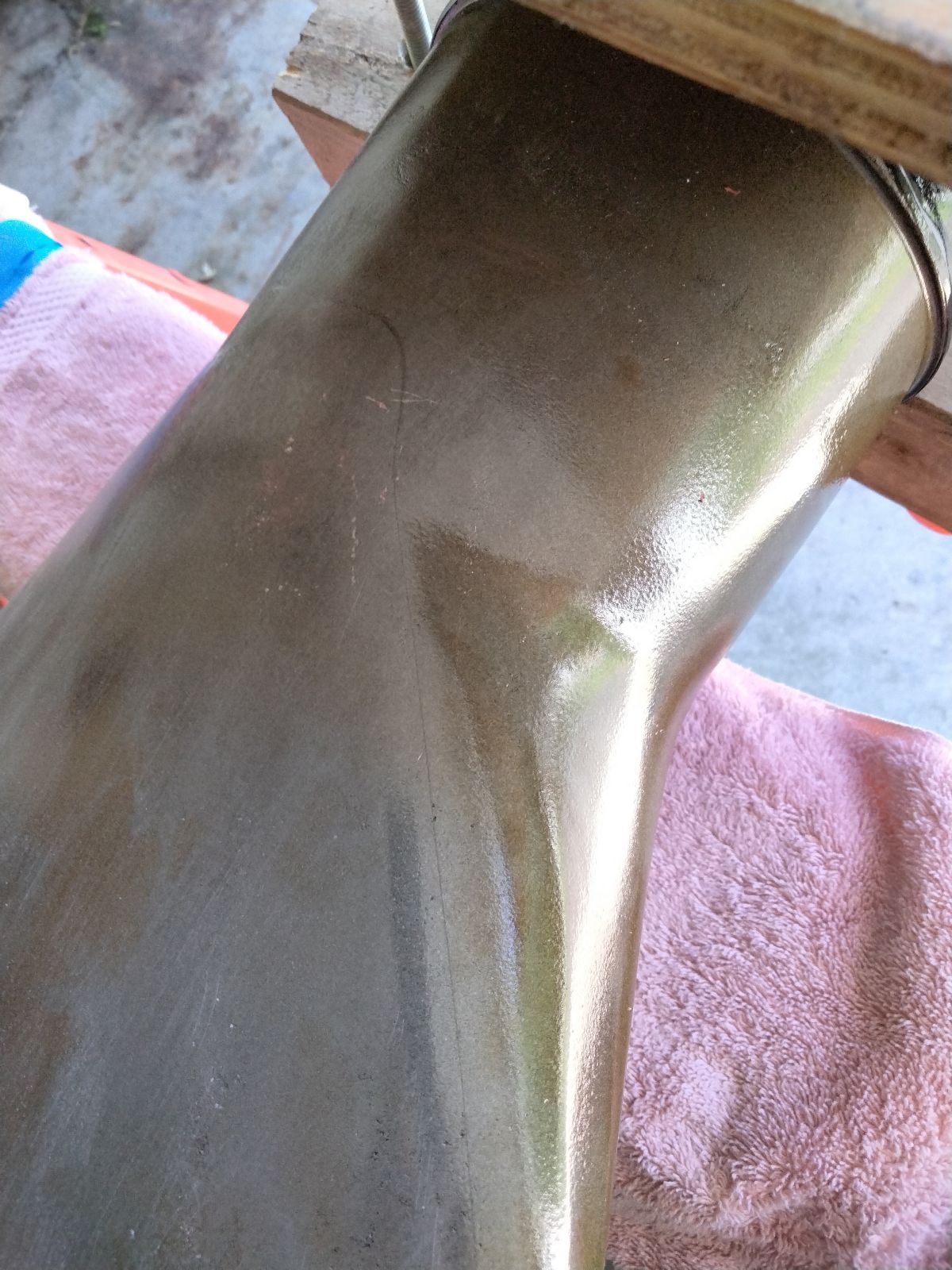
| Pic 12: This locating cross is scribed on the centerline of the blade one inch from the tip. It indicates the 80 inch station, which is precisely 80 inches from the center of the propeller hub. | Pic 13: Serial W.Y. 1321 is stamped in the blade tip. Also of note is the thin braze seam running along the top where the camber sheet meets the thrust sheet. | Pic 14: Brazing seam running along the leading edge of the blade. | Pic 15: The pink line is the brazing seam between the thrust sheet (upper portion in this photo) and the extended camber sheet that is the lower portion of this photograph. The camber sheet extends past the thrust sheet by 2.5 inches to form a trailing edge “flap.” |
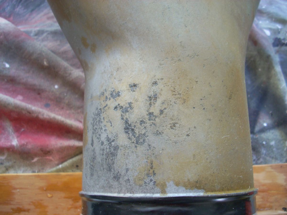
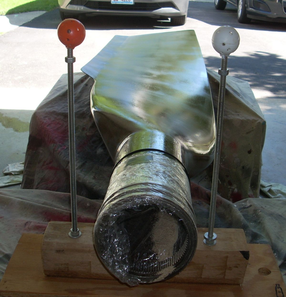
For anyone who has tried to paint a galvanized trash can or basement duct work, zinc has its own requirements for a durable paint finish. I came to learn that treating aged zinc surfaces requires a different chemistry than treating newly-plated zinc surfaces. Acetic acid treatment would rejuvenate the aged zinc, but rapid removal of the acid with distilled water before corrosion of the exposed steel was the challenge. A low-humidity day with a high, baking sun and lots of towels did the trick. (Pic 16, Pic 17) Typical primers are not recommended for coating zinc, but I learned that shellac is the universal primer that will stick to zinc and accept a topcoat of most any type of paint. So after acid wash, water wipe down, and 20 minutes each side in a baking sun, three heavy coats of Zinsser spray can shellac was applied. The blade was now stabilized and preserved. (Pic 18)
The next step was to build a stockade clamp from 4 x 4 wood beams and threaded rod to allow the blade to clamped by the shank to a sawhorse in any desired orientation with the blade tip resting on a second saw horse.
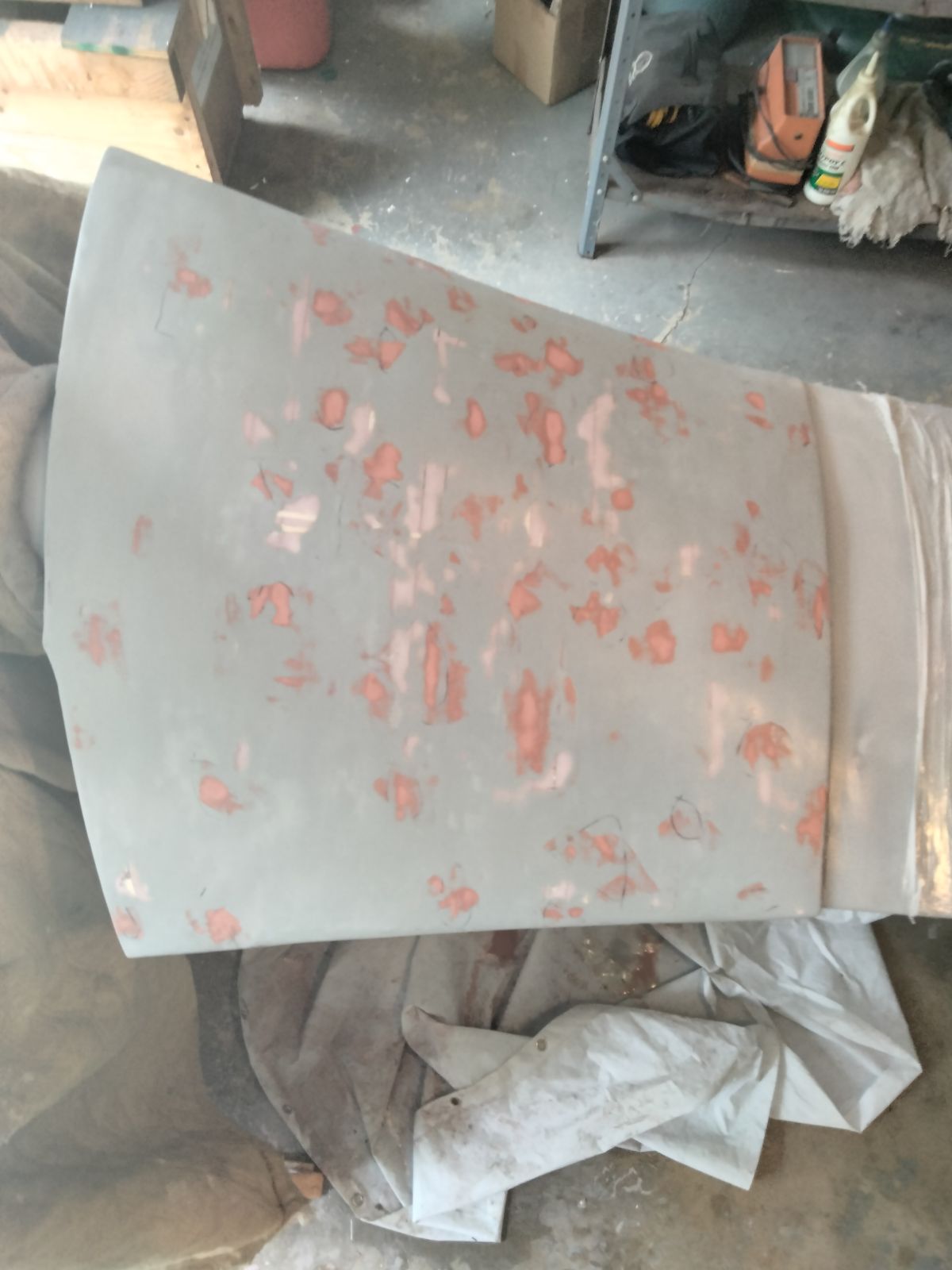
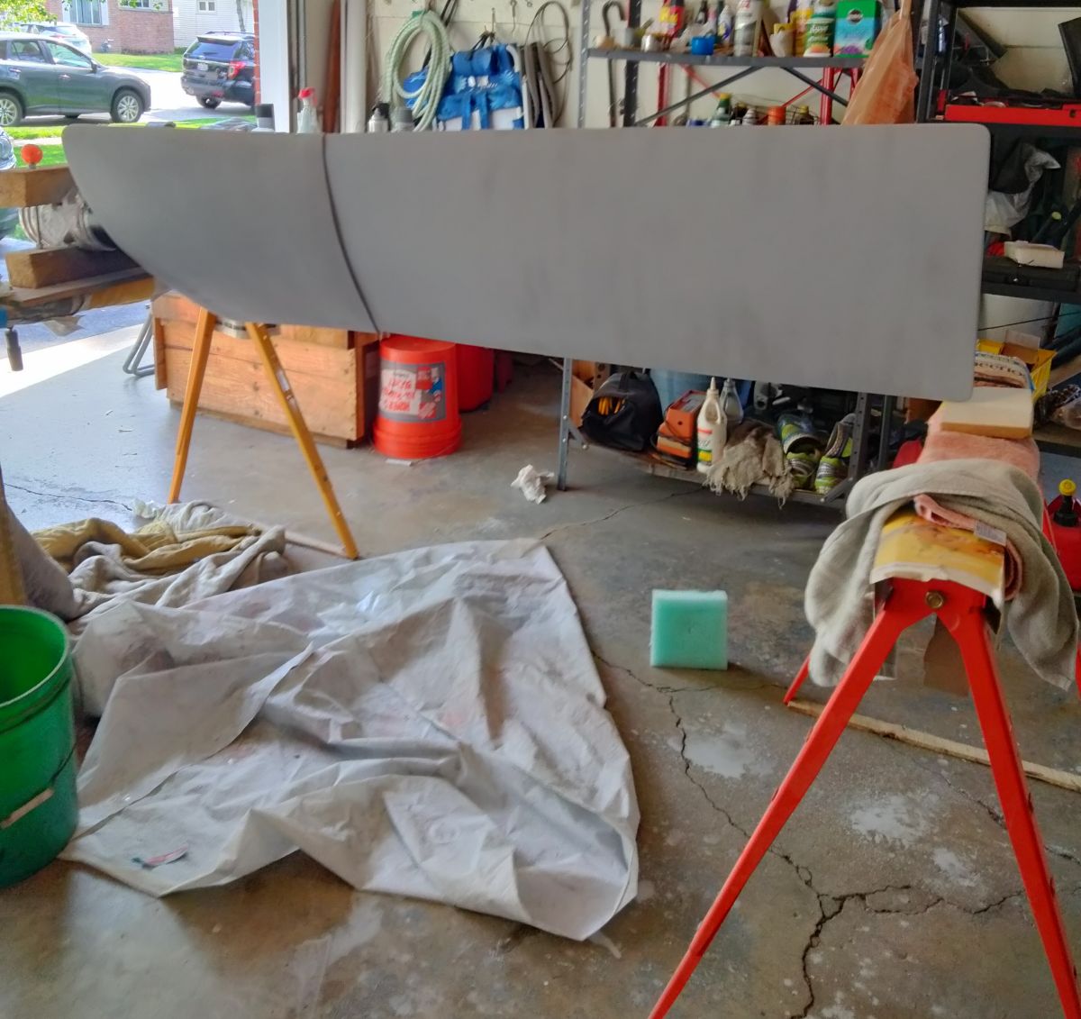
After storage for several months due to winter weather that prevented work in the garage, the shellac was lightly scuffed and the larger pits filled with automotive spot putty. After several rounds of filling and sanding, the blade was primed with rattle can sandable enamel automotive primer. (Pic 19) I was very happy to find no evidence of further corrosion under the shellac.
 |
 |
 |
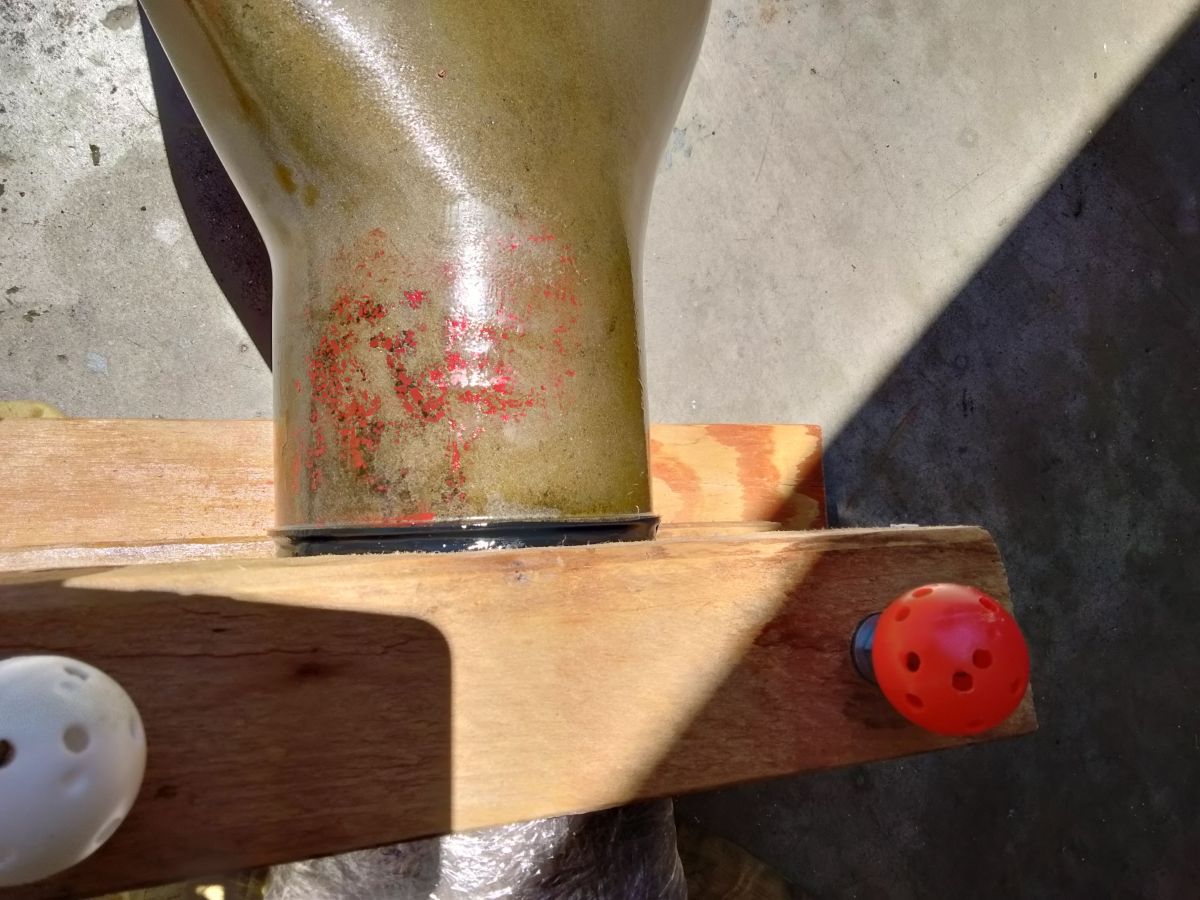 |
| Pic 16: Camber face of blade shown immediately after wash with acetic acid and before washing with distilled water. | Pic 17: Thrust face of blade shown immediately after wash down with distilled water and towel dry. | Pic 18: Thrust face of blade shown after heavy shellacking. Pits are still apparent but the blade is now sealed. Corn cob sandblasting media remains in the hollow shank. Trailing edge “flap” is apparent in this view. | Pic 19: Red automotive spot putty was used to fill the larger pits found on the shank of the blade. |
The original finish on the 248 blade is a very-forgiving semi-gloss black, so various brands of rattle can enamel were tested on the primed blade for color, sheen, adhesion, durability, etc. All brands worked equivalently well but I stuck with Rustoleum products due to cost and universal availability. The lower third of the blade excluding the shank was painted with Satin Canyon Black enamel in preparation for building the cuff.
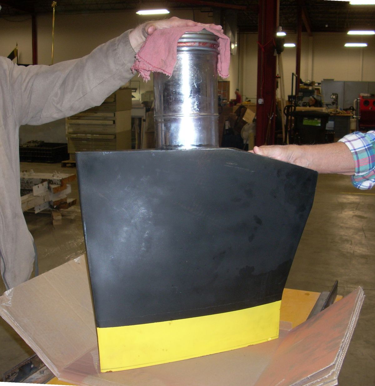
Fortunately, the Trust had excellent documentation on the 248 blade as well as an artifact with partial Aeroproducts cuff for the T56 installation. (Pic 20) Tracings from the bottom of this demonstration blade provided a starting point for lofting the inboard base of the cuff. (Pic 21)
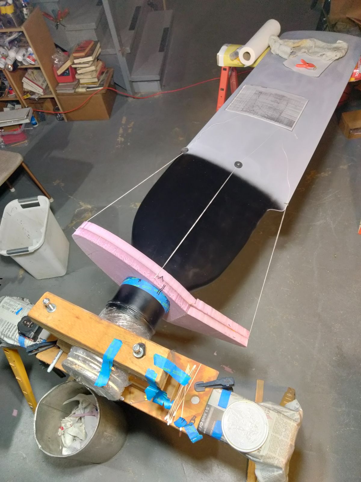
The original cuff was a molded-in-place, fiberglass-reinforced polyurethane unit to which a grid-type electric heating element is bonded to the leading edge for anti-icing. (Pic 22, Pic 23). Cuffs have been unavailable for decades for the 248 blade, so I decided to build the cuff stepwise from 1-inch-thick sheets of Corning Foamular pink insulation. The acquired tracing defined the shape of the root and string mason lines held by magnets defined the cuff perimeter out to the 36 inch station where the cuff ends. (Pic 24) A carbon rod placed on the first lamination and the other end resting on a shim representing the last lamination guide the thickness taper at the midline of the cuff. Just to complicate things, there is variable twist in the cuff from 14.5 inch station to 36 station to account for the lower rotational velocity of the cuff compared to the 45 inches of exposed blade outboard of the cuff. This twist would be eyeballed and left oversize in the roughing process to be refined in the finishing process. Twenty-two unique camber side sections and twenty-two unique thrust side sections were required. Each section was developed by sequential tracings onto manila folders, which in turn acted as templates for tracing onto the foam board and cutting with a scroll saw.
The templates were secured to the blade with silicone sealant and glued to each other with sandable Elmer’s carpenter glue, all held in place with clamps, piano wire pins, and rubber bands for a 24-hour cure.
 |
 |
 |
 |
 |
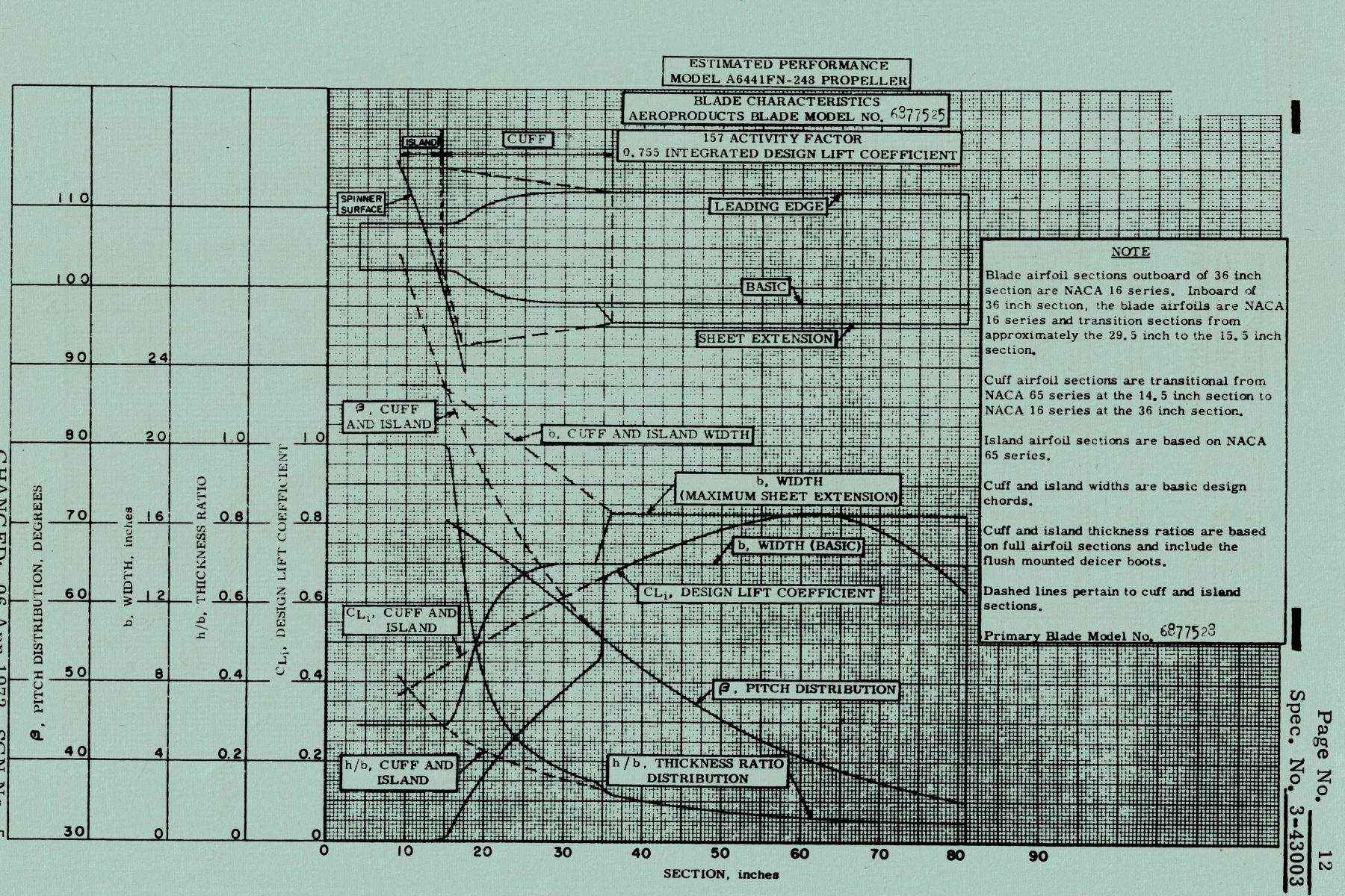
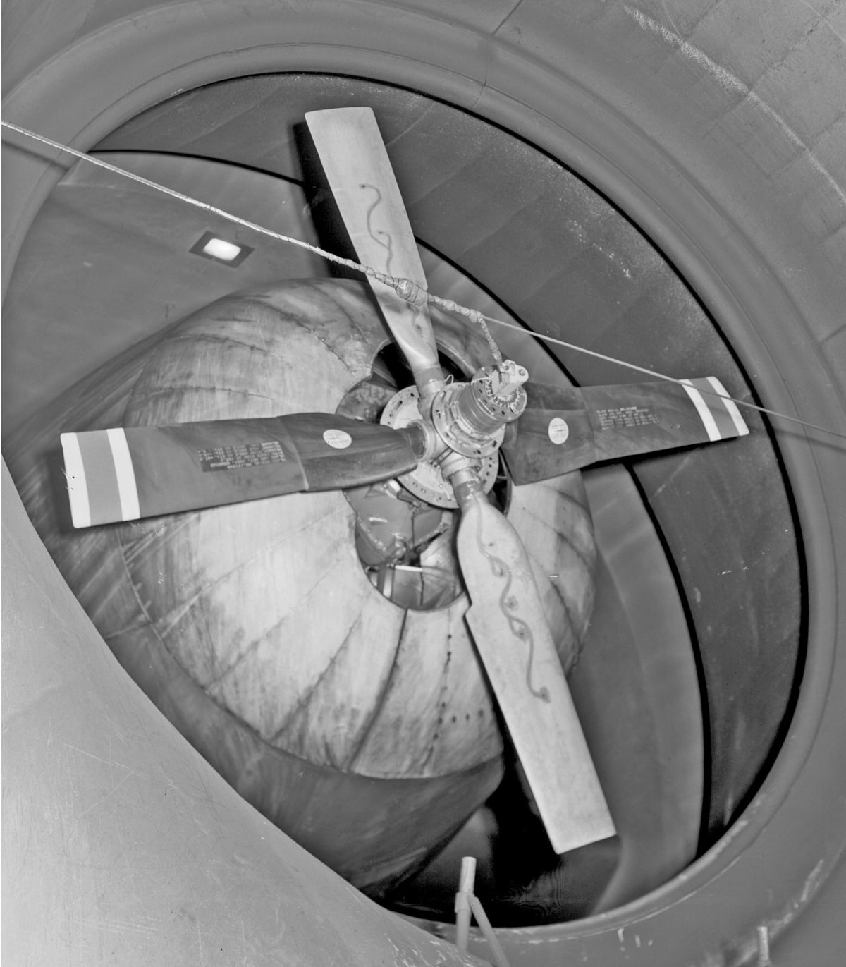
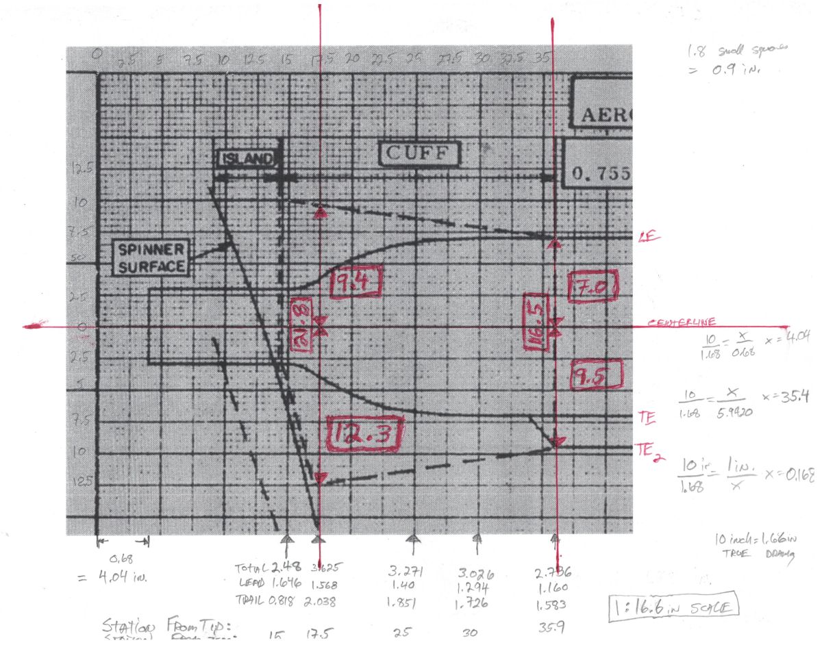
| Pic 20: Specification sheet for the 248 blade from the Allison Model Specification No. 3-43003 document (15-May-1971) showing various data for each blade station from shank to tip as well as the location and planform of the blade cuff. | Pic 21: Stub of an Aeroproducts blade from a cutaway T56 engine/gearbox/propeller display at the RRHT AB in Indianapolis. Tracing the base of the cuff provided a template on which to build the cuff for the 248 blade. | Pic 22: Interesting photo from the RRHT AB archives showing an instrumented A6441FN-248 propeller on the test stand. The cuffless vertical blades have strain gauges on their camber face leading to the brush block “pineapple” on the prop hub to transfer the electrical signals. The horizontal blades have standard blade cuffs. (R-RHT-AB) | Pic 23: The first two laminations of pink foam are the beginning of the blade cuff. White strings help define the perimeters of subsequent laminations. | Pic 24: Aeroproducts A6441FN-28 propeller residing on the Allison T56 of the Grumman E-2A aircraft. The project goal was to replicate the look of this blade. |
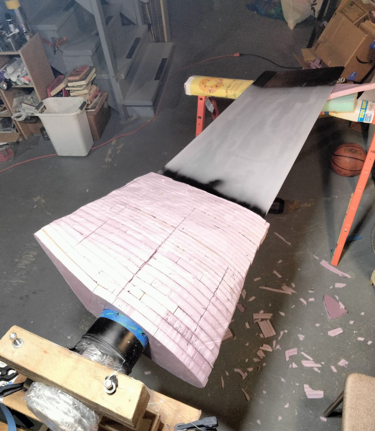
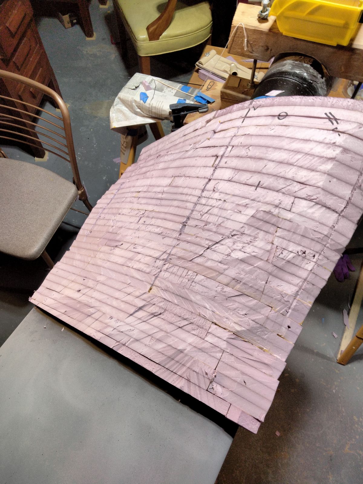
The blade drawing was used to scale the roughed cuff to the proper dimensions. (Pic 25). The distance from blade centerline to cuff perimeter was measured both fore and aft of the centerline to guide the shaping. A 7 inch long, 1 inch chord, flexible thin blade kitchen knife was used to carve the foam roughly to shape. (Pic 26, Pic 27) After that, shaping was done with 60 grit sandpaper on an orbital sander, various rubber blocks, and wood boards to smooth the foam. All this was done in the garage with an open back door, head jamb telltale yarn, and box fan blowing over the work area to keep the dust away from me.
Pink foam is readily dissolved by the solvents in Bondo, spot putty, and enamel spray paints, so a two-part marine epoxy and lightweight 1.5-ounce fiberglass cloth was used to seal and harden the surface of the cuff. (Pic 28) The monotonous cycle of filling, primer spray, and wet sanding without disturbing the epoxy/fiberglass layer eventually smoothed the cuff. (Pic 29)
The blade outboard of the cuff was similarly puttied, sanded, and primed until all the surface blemishes had been remedied.
 |
 |
 |
 |
 |
| Pic 25: Scaling sheet used to determine the dimensions of the finished blade cuff. Red numbers indicate full scale length in inches fore and aft from the blade centerline at Station 17.5 and outboard Station 36. | Pic 26: Thrust face of cuff after rough shaping with knife. | Pic 27: Camber face of cuff after rough shaping with knife. | Pic 28: Lightweight fiberglass cloth overlying the cuff before application of epoxy resin. | Pic 29: Iterative remedy of dents and dimples taking care not to penetrate the layer of epoxy/fiberglass. |
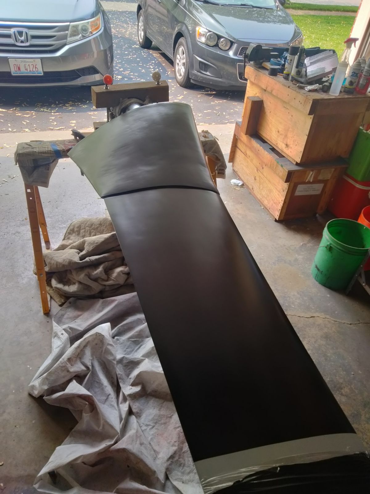
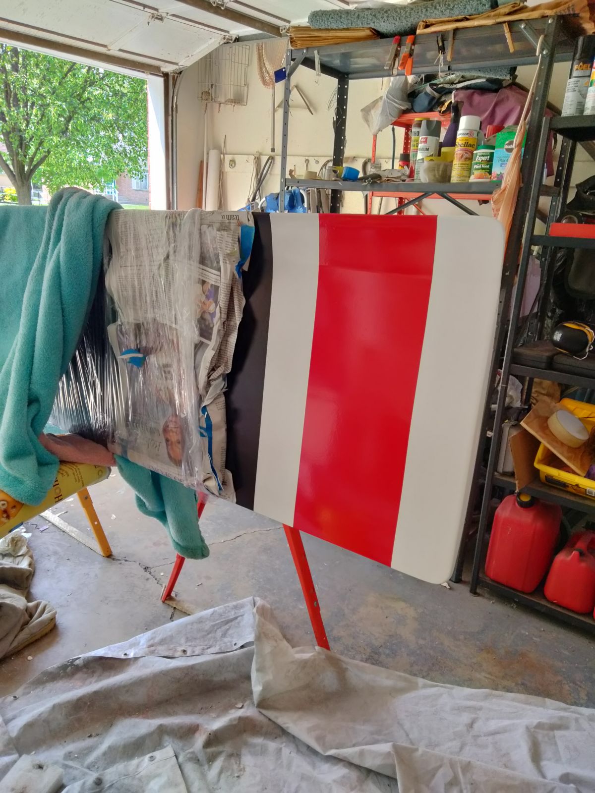
The primed blade received a final wet sanding and wipe down followed by 3 coats of Satin Canyon Black enamel and allowed to cure for several days. (Pic 30, Pic 31) I define “cured” as the paint having no residual solvent odor at the surface. The last 12 inches of the tip on both faces was masked, sprayed gloss white, and allowed to cure a few days. The 6-inch center stripe was masked and sprayed Safety Red and allowed to cure. (Pic 32).
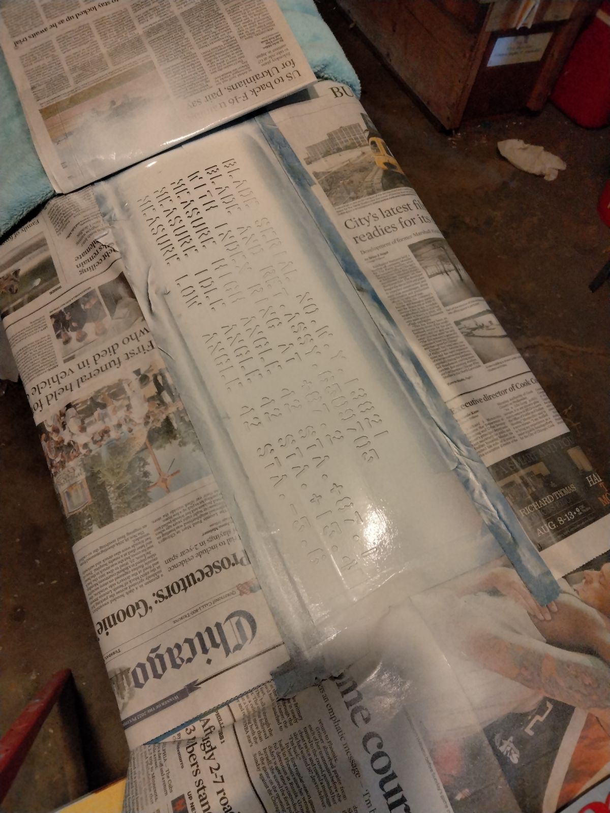
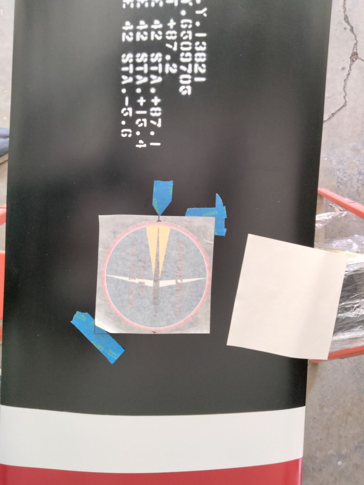
Photographic documentation from the Trust allowed the appropriate stencil to be cut by a propeller shop and with much measurement, flattening, and trepidation, white spray paint was shot as perpendicular as possible over the stencil. (Pic 33) Characteristic of a stencil, the edges of the lettering are variable; some sharp, some soft. Overspray, smearing, or other issues were remedied using a wet cotton applicator stick and automotive polishing compound. Once cured, the stenciled data block was over sprayed with clear enamel as per specs.
The leading edge of the original cuff was wrapped in a heated anti-ice mat that has a different sheen than the rest of the cuff. Trying to replicate the anti-ice mat would tempt disaster, so for simplicity I masked that area and overcoated it with clear enamel, which gives a decent representation of a shiny new deicing panel.
A 2 x 2 wooden dowel was inserted in the hollow shank of the blade to suspend it and allow access for restoration of the shank area and bearing races. (Pic 34) Corrosion on the hardened steel shank was addressed with light oil and green Scotchbrite pads, then polished with Blue Magic metal polish. Once cleaned with lacquer thinner, the shank exterior was sprayed with clear enamel. (Pic 35) The inside of the shank was gently brushed clean and brushed with Ospho 605 to stabilize any corrosion.
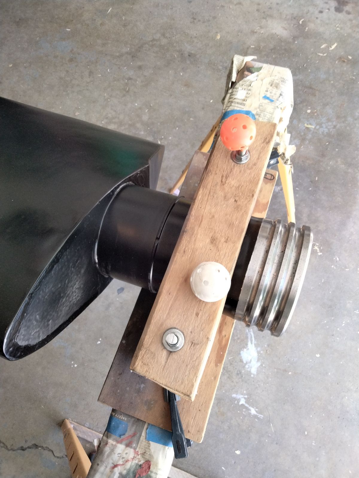
The stockade clamp was used to hold the blade in various orientations for working and painting and ultimately keep the overhung cuff parallel to the ground for transport. It also came in handy to secure the blade vertically to a wall or stanchion for safe storage. The plastic golf balls protect ankles and eyes from the threaded rod.
The piece-de-resistance of the restoration was the application of the distinctive, commercially-available Aeroproducts Turbopropeller logo. Measure the location three times, index the alignment, and apply once, is the rule. (Pic 36)
The restoration was accomplished over 2 years of seasonal and intermittent effort, but it felt like twenty minutes less than forever. But the results are quite satisfying, the Trust has an additional blade for their growing display, and I have my garage back. (Pics 37 - 39)
 |
 |
 |
 |
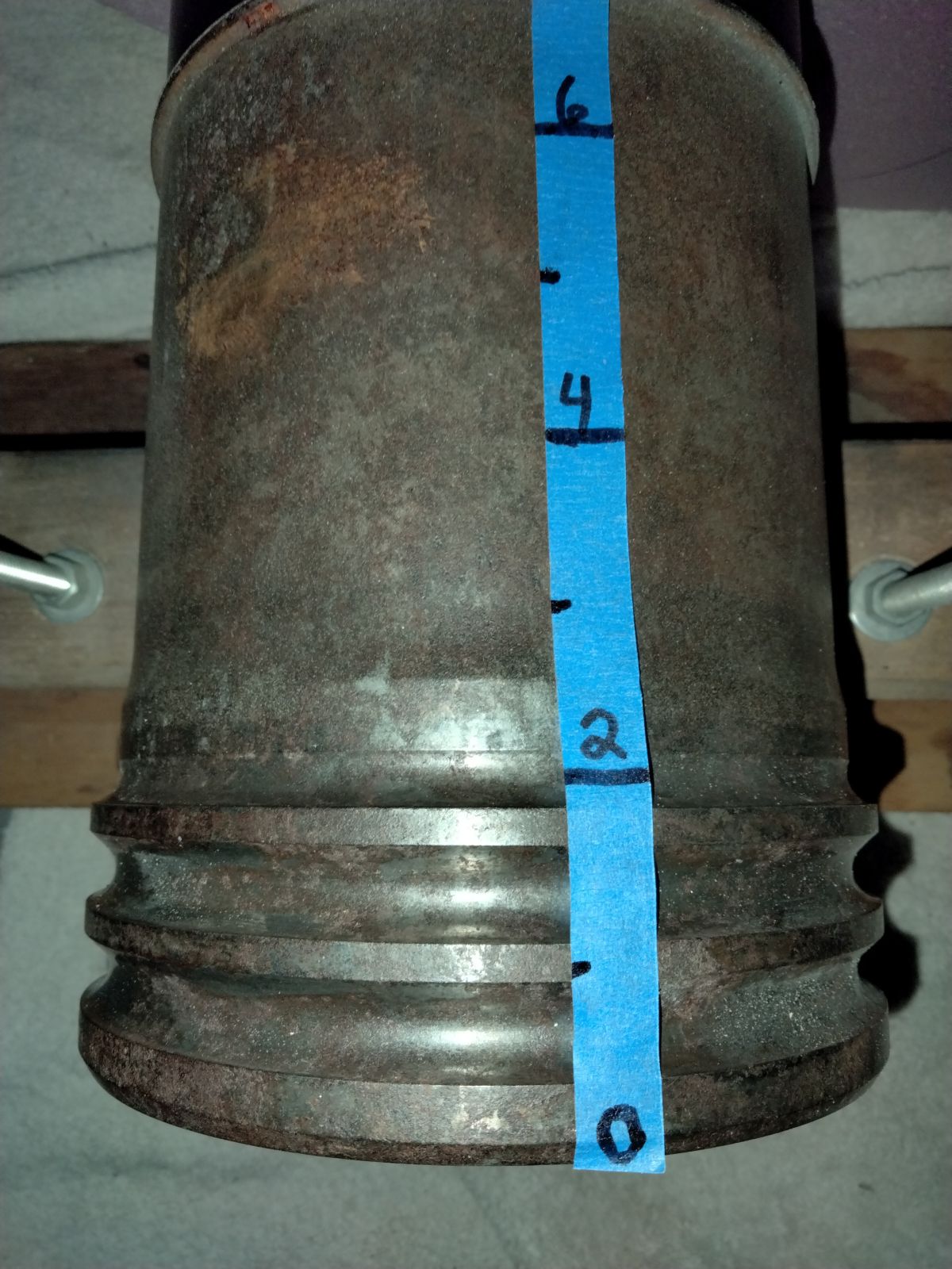 |
| Pic 30: Primed for the final time, ready for finish paint. | Pic 31: Painted with three large spray cans of Satin Canyon Black enamel. | Pic 32: A centered, 6-inch-wide stripe of Safety Red is bordered by two, 3-inch wide stripes of white enamel on both faces of the blade. Thrust face is shown. | Pic 33: After careful centering and alignment of the stencil the letters are sprayed onto the blade with gloss white paint. Spraying lightly and as perpendicular as possible to the surface minimizes misting of edges and bleed under the stencil. | Pic 34: Close up of the blade shank showing the three integral bearing races. The markings on the blue tape are in inches to guide the design of a display stand. |
 |
 |
 |
 |
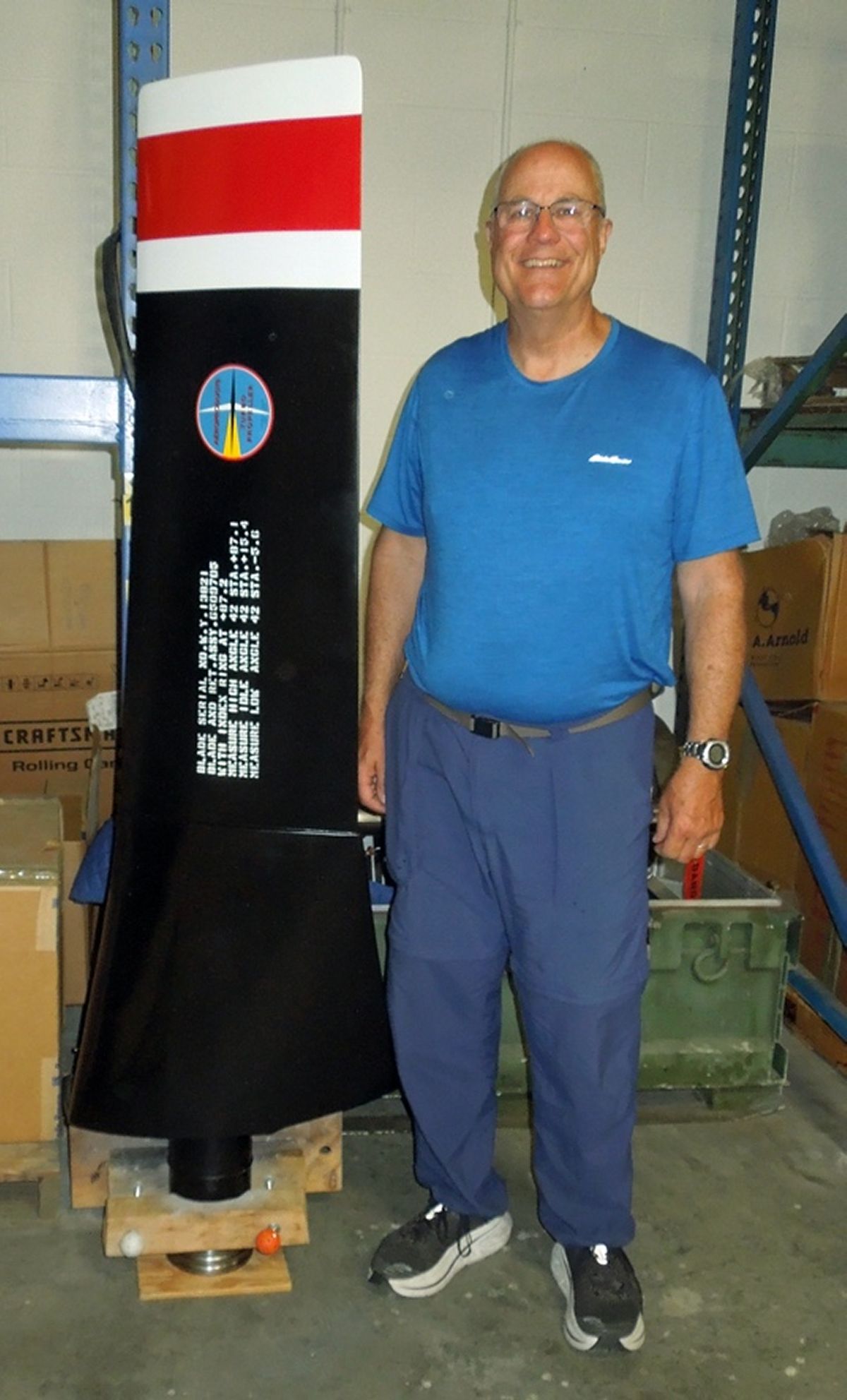 |
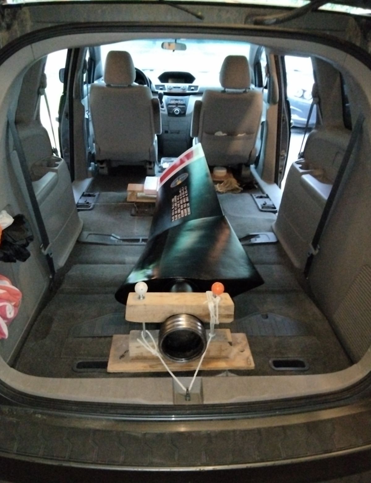
| Pic 35: Blade shank ready for display. | Pic 36: Alignment of the vinyl Aeroproducts logo on the blade. It is nerve wracking. | Pic 37: Remaining steps are to overspray the stencil data with clear enamel and apply a 2-inch x 1/8-inch yellow stripe decal at the 42 inch station on the thrust face of the blade. | Pic 38: Blade secured in Honda Odyssey for the trip back to Indianapolis. The stockade clamp keeps the cuff off the floor. | Pic 39: The 248 blade in Indianapolis awaiting its display stand. |
Send mail to
![]() with questions or comments about this web site.
with questions or comments about this web site.
![]()