The Hamilton Standard Variable Camber Propeller
by Tom Fey
Published 1 Aug 2020; Revised 27 Jun 2021
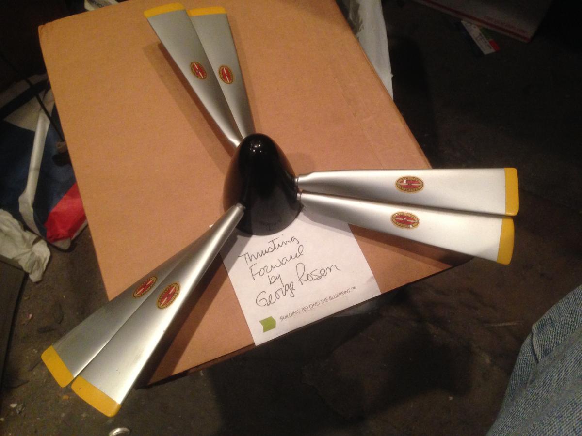
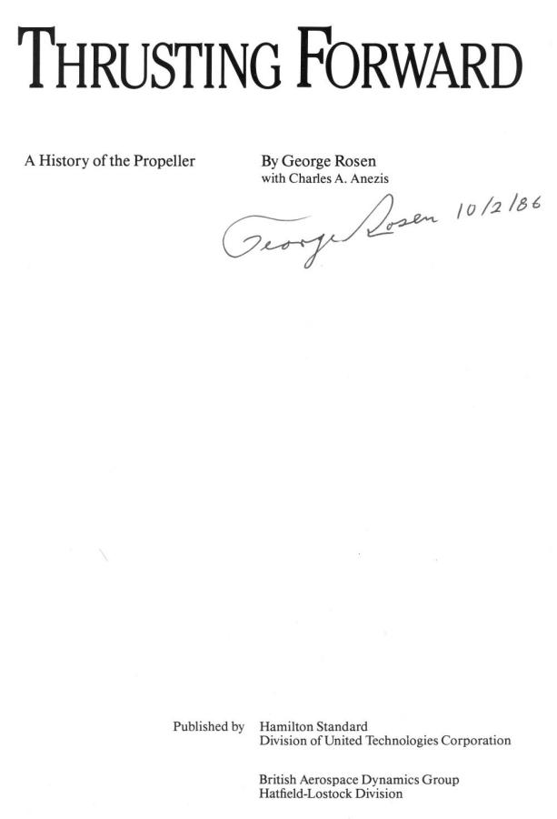
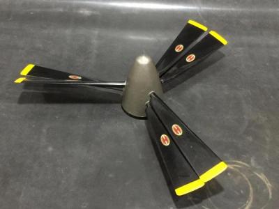
Figs. 1, 2. Manufacturer’s Model of the Hamilton Standard Variable Camber Propeller and Title Page of Thrusting Forward, written and signed by George Rosen, 10-2-86. Both are in the collection of Monte Chase. (Photos by M. Chase)
|
You never know what may turn up along the way, and that was the case in 2012 when I purchased some propeller decals from a gentleman named Monte Chase who has a world-class collection of meticulously restored aircraft propellers.
In addition to his full scale propellers, Monte had a spectacular manufacturer’s model of a unique propeller along with a copy of a book written by the inventor of the propeller, George Rosen, in his collection.
Interested in both, but saving pennies at the time, I passed on acquiring the inseparable pair. (Figs. 1, 2) |
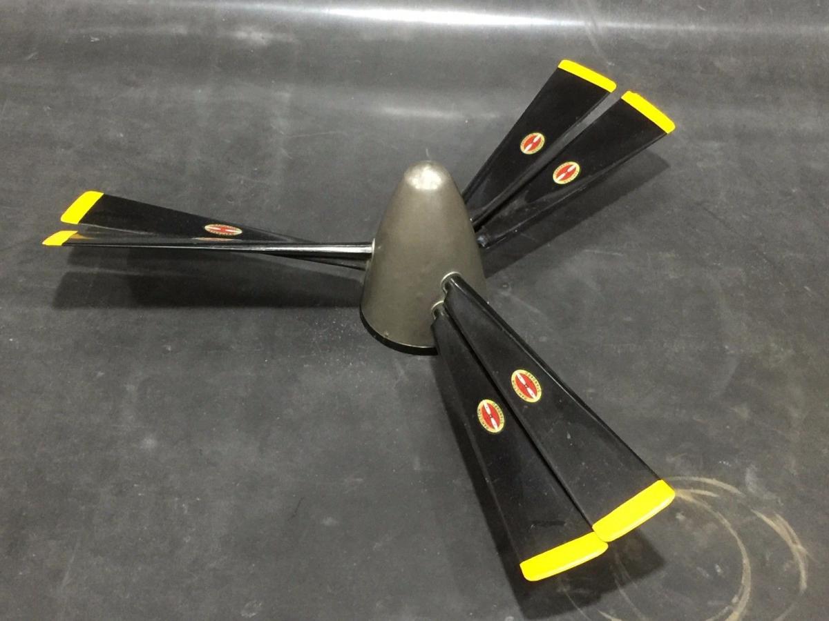
Fast forward to an eBay listing in December of 2017 for a manufacturer’s model of a Hamilton Standard contra-rotating propeller that was 14 inches in diameter. It was not a contra-rotating propeller, and except for the inverted color scheme on the blades and spinner, it was identical to Monte’s model. I bought the model immediately, tracked down a copy of George Rosen’s book Thrusting Forward, and started my research on the propeller. (Figs. 3, 4)
 |
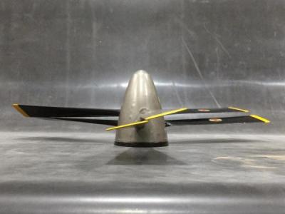 |
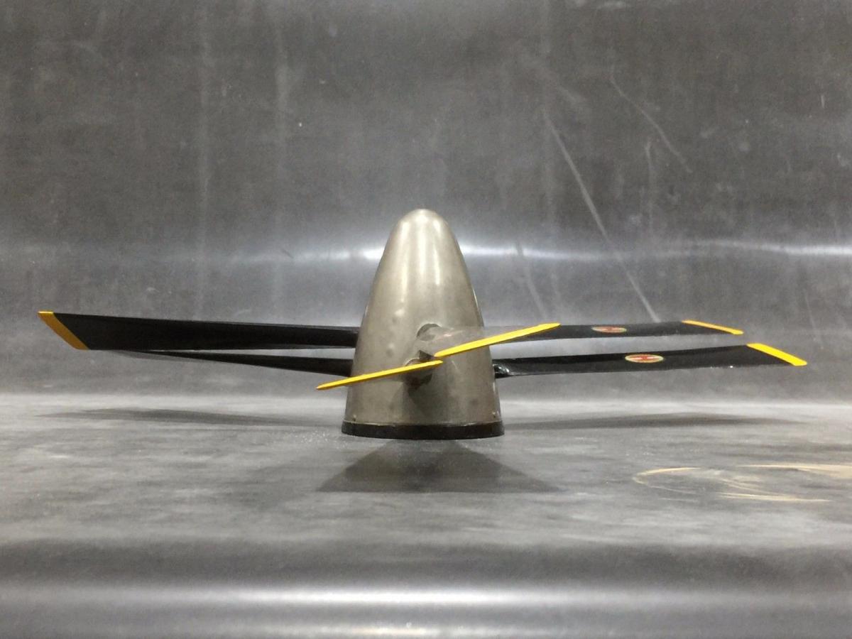
| Fig. 3. Manufacturer’s model of the Hamilton Standard Variable Camber propeller in the collection of Tom Fey. Fourteen inches in diameter, white metal spinner, plastic blades and back plate. Made by Model Makers Products Inc. (Photo by T. Fey) |
Fig. 4. Manufacturer’s model of the Hamilton Standard Variable Camber propeller in the collection of Tom Fey. Blades depicted in the cruise position for high speed flight.
(Photo by T. Fey) |
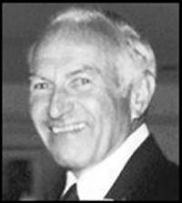 |
| Fig. 5. George Rosen (1914-2004) was the inventor and patent holder of the Variable Camber propeller. (Photo by the Hartford Courant) |
George Rosen was a Massachusetts Institute of Technology (MIT) graduate aeronautical engineer, class of 1937, who went to directly to work for Hamilton Standard as their first propeller aerodynamicist. George had long and distinguished career at Hamilton Standard, winning the United Aircraft Mead Medal in 1961 for the variable camber propeller and the Goddard Award from the American Institute of Aeronautics and Astronautics (AIAA) in 1975 for his many contributions to the turbine propeller. Rosen retired as Chief of Propeller Research and Development in 1977 after forty years of service that spanned the heyday of the propeller. He was also a great patron of the arts and an accomplished sculptor late in his life. (Fig. 5)
Propeller design is typically optimized for a specific phase of flight, most often, efficiency in high speed cruise. One of the ongoing challenges of propeller propulsion is to provide the ability for high thrust for takeoff with high thrust but low drag for cruise flight. Highly cambered propellers generate tremendous thrust at low airspeeds, but are draggy and thus inefficient in the high speed flight regime. Very thin propeller blades work well at high speed cruise, but have reduced thrust profiles at low airspeeds such as takeoff. Variable pitch, constant speed propellers address this challenge quite well as long as runways are sufficiently long. But what about optimizing performance for missions that require short takeoff and landing (STOL) or vertical takeoff and landing (VTOL)?
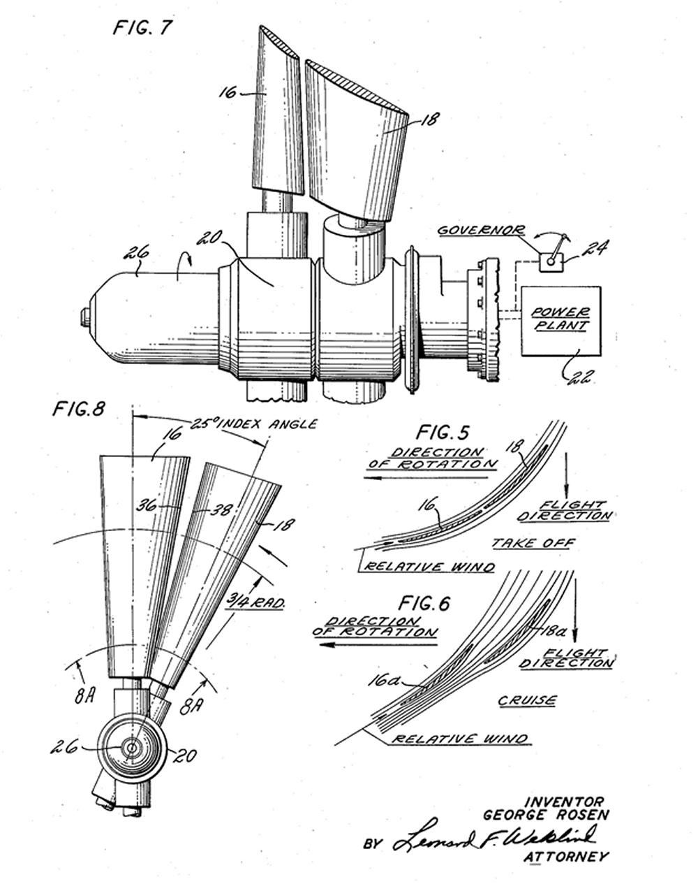
George Rosen conceptualized an engineering approach to this “high thrust at low airspeed but efficient cruise” requirement with the variable camber (VC) propeller. His idea was to use two rows of propeller blades on the same single-rotation hub. The aft propeller disc would be displaced axially behind the fore prop disc, and the blades themselves would be offset by 25° between the rows. The pitch of each disc (row) of propeller blades could be adjusted independently of each other. (Fig. 6) This allowed the trailing blade to perform essentially as a slotted flap to the leading blade. George Rosen submitted a patent application for his invention on 19 December 1958 and was granted US Patent 2,982,361 on 2 May 1961.
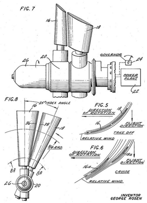 |
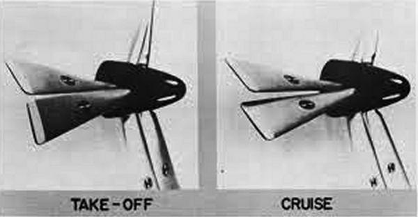
| Fig. 6. George Rosen’s US Patent No. 2,982,361 shows the orientation of the variable camber propeller blades on the hub (Figs.7,8) as well as their pitch orientations for takeoff (Fig.5) and cruise flight (Fig.6). |
For takeoff, when a cambered blade profile is desired, the fore blades would be at a lower pitch than the trailing blades (Fig. 7). Once higher speeds were attained, the blades of the aft disc could be adjusted to align parallel with the leading blades. In addition, the variable camber propeller was also a constant speed propeller, meaning the pitch of both blade sets could be moved in lock step to keep the propeller RPM at a selected value while power was applied or reduced during flight.
The variable camber propeller was also expected to produce more than 4 lb of thrust per shaft horsepower, which at the time was projected to be minimal requirement for VTOL aircraft. Because of its six blades, and eight blades in later designs, the large blade area of the VC propeller could efficiently absorb the burgeoning horsepower produced by that generation of turboshaft power plants.
 |
| Fig. 7. A model propeller showing, in exaggerated form, the pitch orientations for the fore and aft propeller discs for takeoff and cruise flight conditions. Actual pitch differential in the cambered orientation was approximately 10° according to the Rosen patent reproduced in Figure 16. (Photo from Thrusting Forward) |
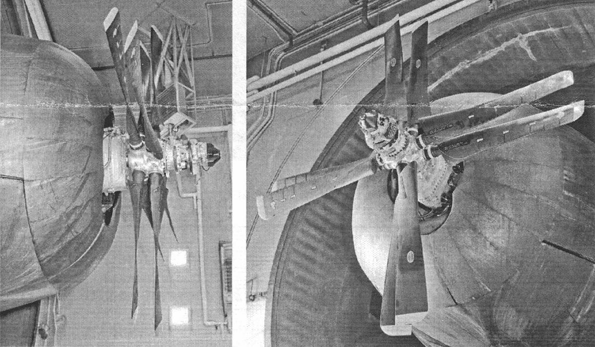
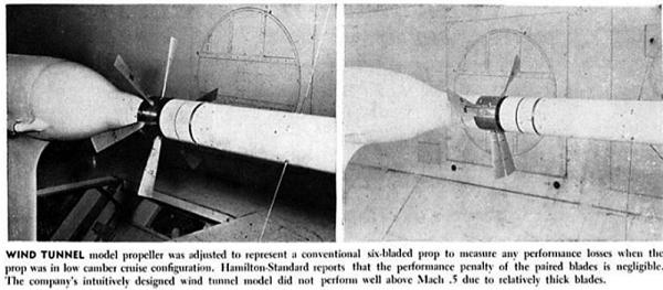
Investigation into variable camber propeller began in 1958 at Hamilton Standard, but a 15 August 1960 article in Aviation Week, states that up until that time, all resources had been applied to wind tunnel models to validate the concept and assure no degradation in cruise performance with the tandem blade arrangement. (Figs. 8, 9). This work was supported by a $350,000 contract with the US Navy.
 |
 |
| Fig. 8. A 2.5 foot diameter six blade propeller (left) and six blade variable camber propeller (right) in the United Aircraft Research Laboratories wind tunnel. This allowed direct comparison of the two different blade configurations. (Barry Tully, Aviation Week, 15 August 1960)
|
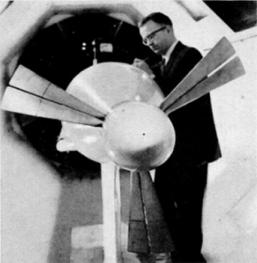
Fig. 9. Wind tunnel model of the variable camber propeller. The diameter of the spinner is seven inches. (Barry Tully, Aviation Week, 15 August 1960) |
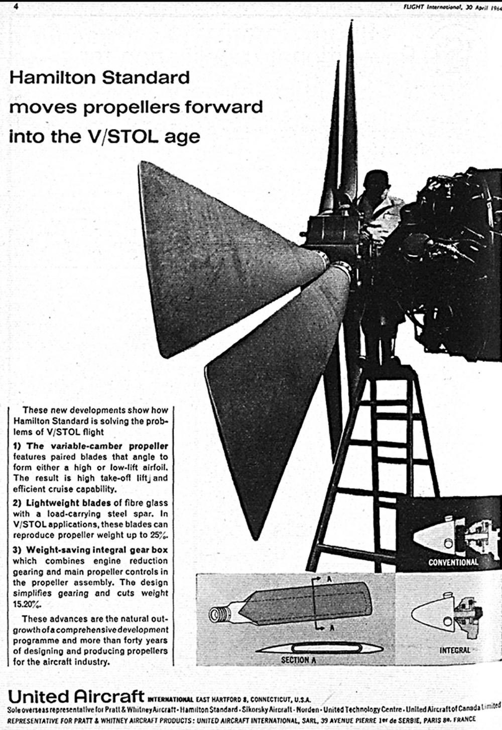
An April 1964 advertisement in Flight International shows a photograph of early test work on the VC propeller concept in what looks like a ground-adjustable hub driven by a Pratt & Whitney R-4360 piston engine. (Fig. 10)
 |
| Fig. 10. Advertisement showing the VC propeller on a test stand. The hub might be a ground adjustable type hub and the engine is a Pratt & Whitney R-4360, a 28 cylinder radial piston engine of 3,000 horsepower. (Flight International, 30 April 1964) |
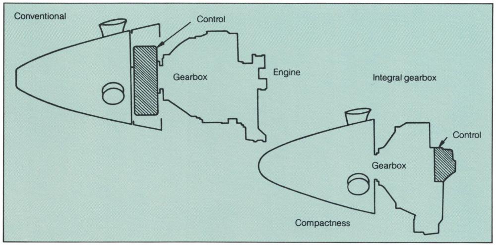
The Hamilton Standard VC86260 variable camber propeller was developed for flight testing with preliminary funding from the US Navy arriving in late 1964 and a further contract in mid-1965. The variable camber prop was designed to be driven by a General Electric T64 turboshaft engine of up to 3,200 horsepower via an “integral” gearbox. The integral gearbox used on the T64 was an evolutionary design intended to reduce weight and complexity in turbopropeller installations. The propeller controls were designed into the gearbox itself, and the whole propeller-gearbox-propeller control became a one-piece integrated unit. (Figs. 11, 24). Rosen and period ads state that use of the integral gearbox could save up to 15%, and the use of steel spar/fiberglass blades up to 50%, of installed weight of these components as compared to typical installations using duralumin blades and separate gearbox, propeller, and propeller control assembles.
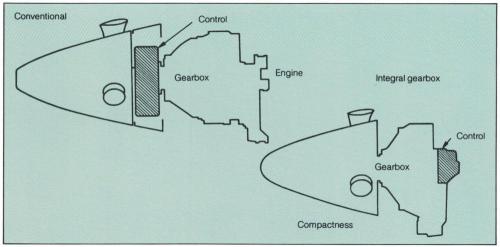 |
| Fig. 11. Schematic representation of the integral gearbox compared to a typical gear box assembly. The object was to save weight by using shared instead of separate component support structures. Weight savings up to 15% were expected. (Photo from Thrusting Forward) |
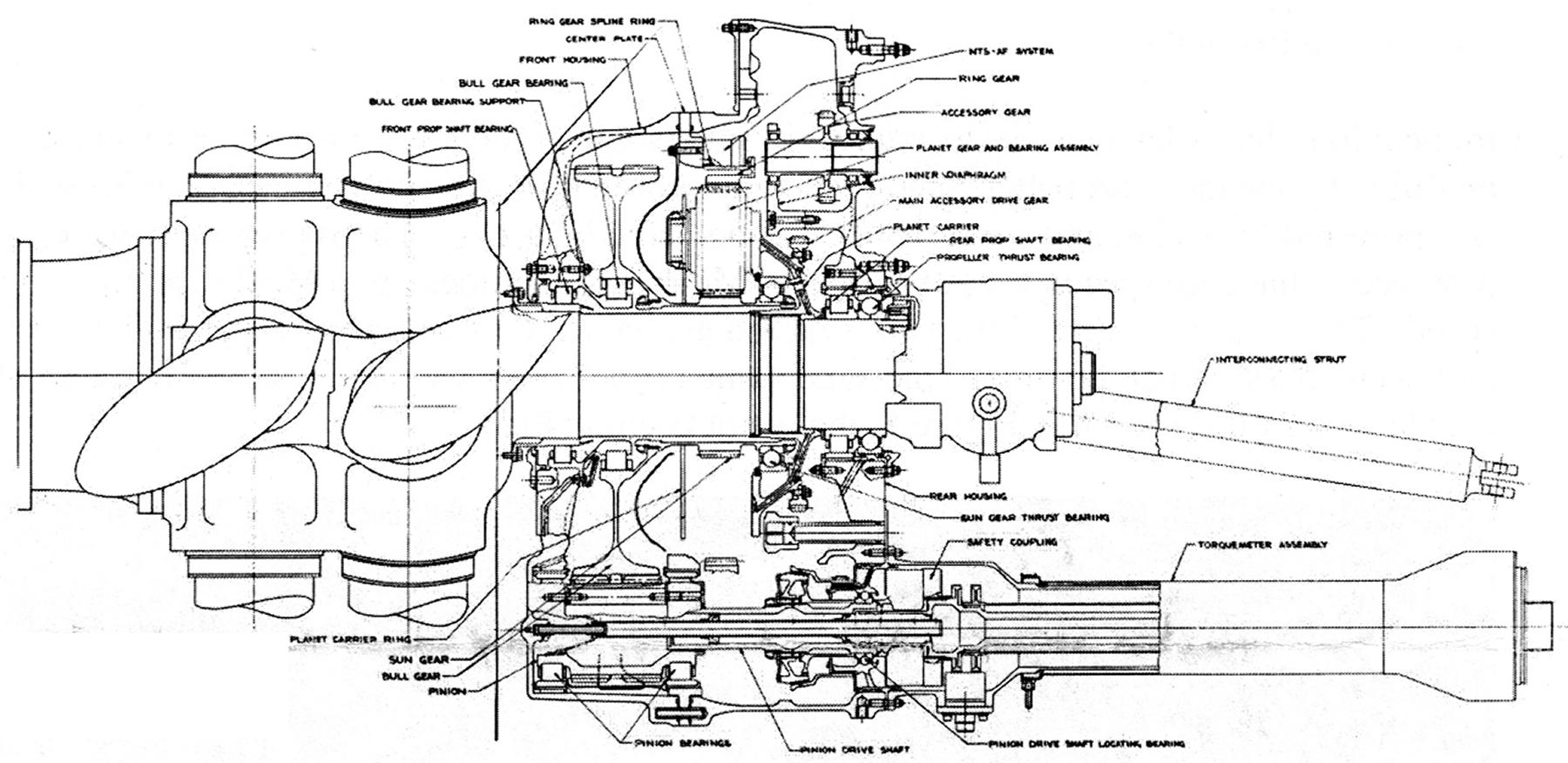
The larger, VC82S eight blade propeller was tested on a Navy contract driven by an Allison T56-A-18 engine of 5,000 shaft horsepower in Indianapolis Indiana. (Fig. 12) As described by Rolls-Royce Heritage Trust historian John Leonard, the T56-A-18 gearbox had a reversed drive path through the planetary gear reduction train compared to standard T56 configuration. This offered three advantages:
- The main thrust bearings were now spaced further apart which provided better support.
- The enlarged space in the propeller shaft allows room for additional propeller control channels.
- Repositioning of the thrust bearing to the aft end of the gear case relieves the body of the gear case of the thrust loads. (Fig. 13) Greater support for the propeller shaft as well as increased tolerance to thrust loads was a great match for a large propeller that could generate high static thrust loads. Note the stress gauges on the blades and the “pineapple” electrical data transfer device on the propeller hub. (Fig. 12).
 |
 |
| Fig. 12. The eight blade Hamilton Standard VC82S propeller on the test stand at Allison in Indianapolis, Indiana, USA. This propeller is much larger than the six blade VC86260 propeller and was driven by an Allison T56-1-18 turboshaft engine of 5,000 horsepower. (John Leonard / Rolls-Royce Heritage Trust) |
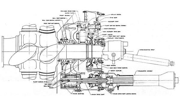
Fig. 13. Diagram of the modified Allison T56 gearbox for the eight blade VC82S propeller. Power input comes from the shaft at the lower right into the spur gear pinion at lower left. This pinion engages the large diameter bull gear, which is integral with a sun gear. The sun gear drives the planetary gear against a stationary ring gear. The orbiting planetary gear carrier is splined to the propeller shaft.
(John Leonard / Rolls-Royce Heritage Trust) |
The SK50629 integral gearbox for the six blade VC86260 / T64 project was designed for up to 3,180 hp 1,200 lb/ft torque with input at 15,600 rpm (17,000 rpm max) and a 12.08:1 reduction ratio. The gearbox was tested for 37 hours 25 minutes of run time without issue in the Hamilton Standard “E” test cell driven by a General Electric T64-GE-1 engine. It was then disassembled, found to be in excellent condition, and cleared for the 50 hour flight test performance trials.
The very clever actuation system of the VC86260 propeller was designed and ultimately patented by Hamilton Standard engineers Phillip E. Barnes, Seppo J. Viikinsalo, and Richard B. Pitbladdo on 29 December 1964. It was a constant speed, feathering, and reversing propeller which used two independent but interleaved cylinder spaces in the hub center in which each space controlled the pitch of one disc set (Fig. 14). The cylinders were splined to the propeller hub to prevent their rotation inside the hub but were free to translate fore and aft under metered hydraulic pressure from the propeller governor. The cylinders had slot-type cams in their periphery that engaged eccentric pins on the base of the propeller blades to rotate the blades. Unlike most Hamilton Standard split hubs used at the time, the VC propeller hub was a one-piece forging.
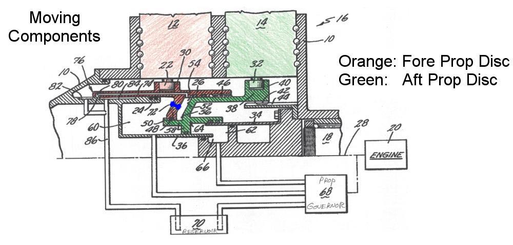 |
| Fig. 14. Schematic representation of the moving components of the VC propeller hub. Components in orange are associated with the forward propeller disc. Components associated with the aft propeller disc are in green. The sliding cylinders have slit cams or yokes that engage the eccentric pins on the base of the propeller blade to change the pitch of the blades. (US Patent 3,163,231) |
Between the two cylinder spaces was a third space indexed as Number 56 in Figure 15. This third space could be filled to force the respective disc cylinders apart, creating the high camber configuration. When pressure was relived from the third space, blade moments pressed the prop disc cylinders together, emptying the third space up hard against stops, creating the “blades in cruise” configuration for high speed flight. The oil flow into the third spaces was ported through a translating valve (Number 80) that opened at defined pitch settings of the fore disc blades. The third space was emptied by closure of the inlet and blade moments forcing the hydraulic fluid out through via a metered orifice (Number 72) into the fore disc cylinder. The blade indexing schedule is described in the Rosen patent, Figure 16.
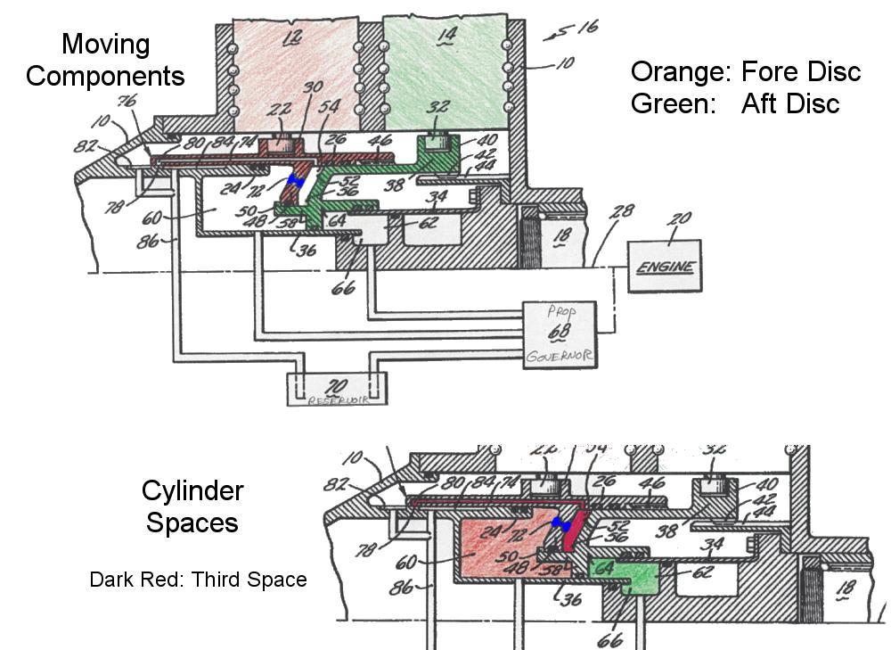 |
| Fig. 15. Schematic showing the moving components in the upper left and the three hydraulic cylinder spaces of the VC propeller hub in the lower right. The orange cylinder space (60) drives the forward propeller disc pitch change. The green cylinder space (66) drives the pitch of the aft propeller disc. The red space (56) is fed by a translating inlet valve (80) and drains into the fore cylinder space (60) via a metered port (72, in blue). The diagram shows the “cambered” blade condition with the third space expanded to its hard stop (50). The inlet (80) remains open thus blades remain cambered to each other, but now move as a unit fore or aft to maintain constant speed of the cambered blade configuration as directed by the prop governor. When blades are in the parallel cruise flight, the inlet port (80) is closed, the red third space (56) bleeds to empty via the metered port (72), and the fore and aft sliding components are pressed together and move as one unit either fore or aft to maintain constant speed of the blades in trail configuration as controlled by the propeller governor (68). (US Patent 3,163,231) |
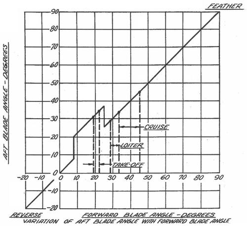 |
| Fig. 16. Blade scheduling diagram for the fore and aft propeller discs. The cambered blade configuration is indicated by the mesa shaped bump on the curve. There is approximately 10° differential between the blade sets in the cambered configuration and no differential in the cruise condition. (US Patent 3,163,231) |
Variable pitch propeller blades, unless otherwise counter balanced, will turn themselves towards flat pitch by the centrifugal forces acting upon them when spinning. This “blade moment” can be used as the motive power to move blades to fine pitch while considerable hydraulic or electrical force must be applied to the blades to coarsen / increase their pitch.
The third space in effect hydraulically-locked the fore and aft blade cylinders into one of two positions: cambered or trail. This allowed the whole cylinder assembly to move as one unit as the fore cylinder was fed metered oil under pressure by the governor to maintain constant speed, regardless whether the blades were in the cambered or trail positions. The moments of the six or eight large blades provided the power to return the blades towards flat pitch when the aft cylinder was opened to drain. The propeller governor would either supply or drain the forward or aft cylinder spaces according to a divergence in rpm to change pitch and maintain a constant speed.
The specifications of the VC86260 propeller are defined in Hamilton Standard Model Specification No. 5006A, but I have been unable to locate this document. Fortunately, the 182 page "Propeller Integral Gearbox 73EGB1 and Propeller Variable Camber Model VC86260 Flight Test Report” dated 30 June 1966, is available and can be found in the AEHS Members’ Section. It is a wonderful technical document with typed and hand-generated tables, graphs, and charts of the data acquired during the two 50 hour flight test programs as well as test cell work on the gearbox and propellers. It also has several pages of horrifically reproduced photographs.
The VC86260-5 propeller used in flight testing was 13 feet six inches in diameter and used identical 2FD14A3-6 blades in all six hub sockets. Of note is that the VC propellers had at least two different blade shapes. The early shape with square tips appears in the early 1960s literature and this blade shape, with cuffs, was clearly used in the 50 hour flight testing in 1966. An alternate blade shape with rounded outer tips appears on the VC82S Allison test stand photographs as well as on the six blade VC prop in a 1969 article discussing propeller noise reduction. It can be assumed that the blades themselves were the tubular-steel -sparred, foam filled, and fiberglass sheathed design that Hamilton Standard had developed and produced for naval aircraft flying at that time. (Fig. 17) Also of note is that the inverse taper of the VC propeller blade, thus the maximum chord of the propeller blade is at the tip, and this geometry provided a near-constant gap between the blades from root to tip.
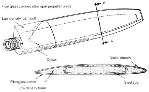 |
| Fig. 17. Alternate Hamilton Standard Blade Shape and Construction |
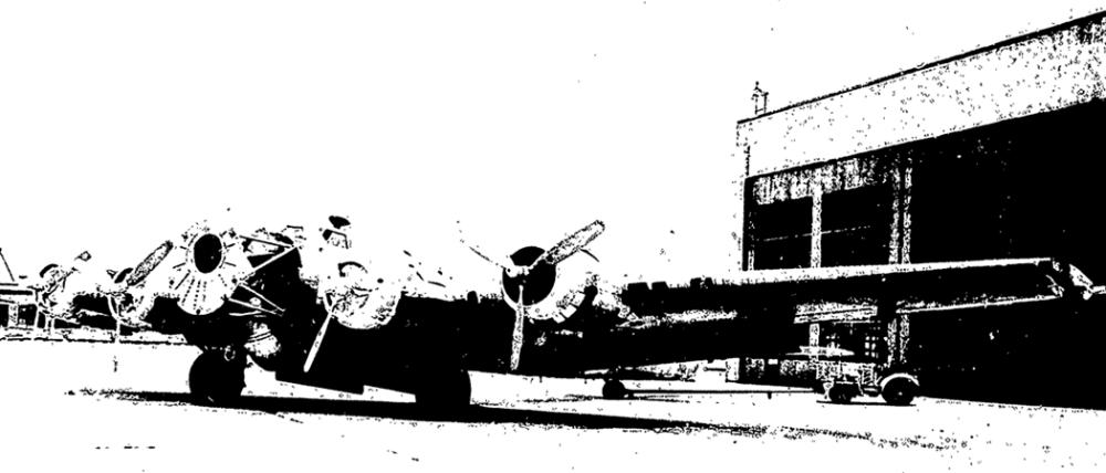
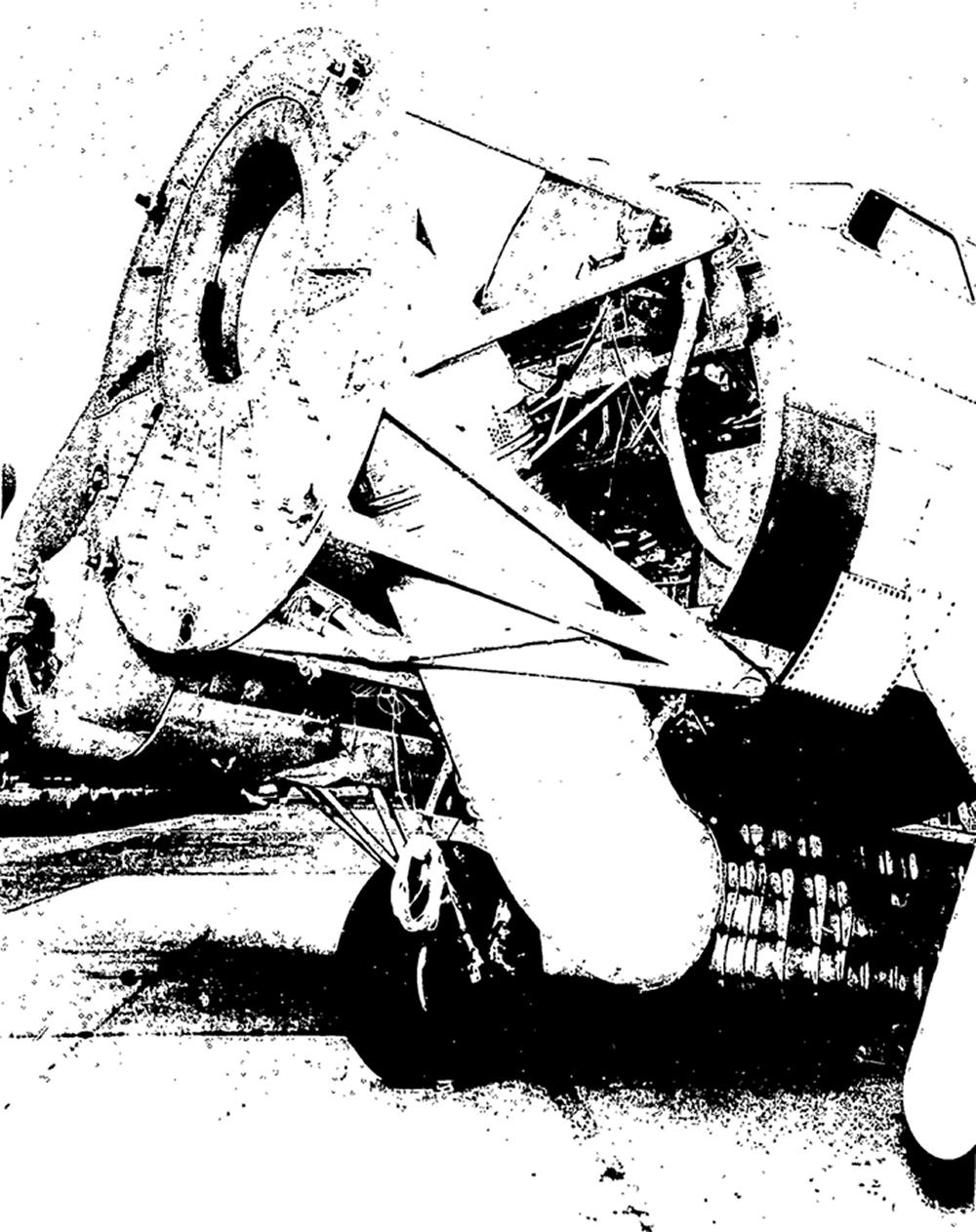
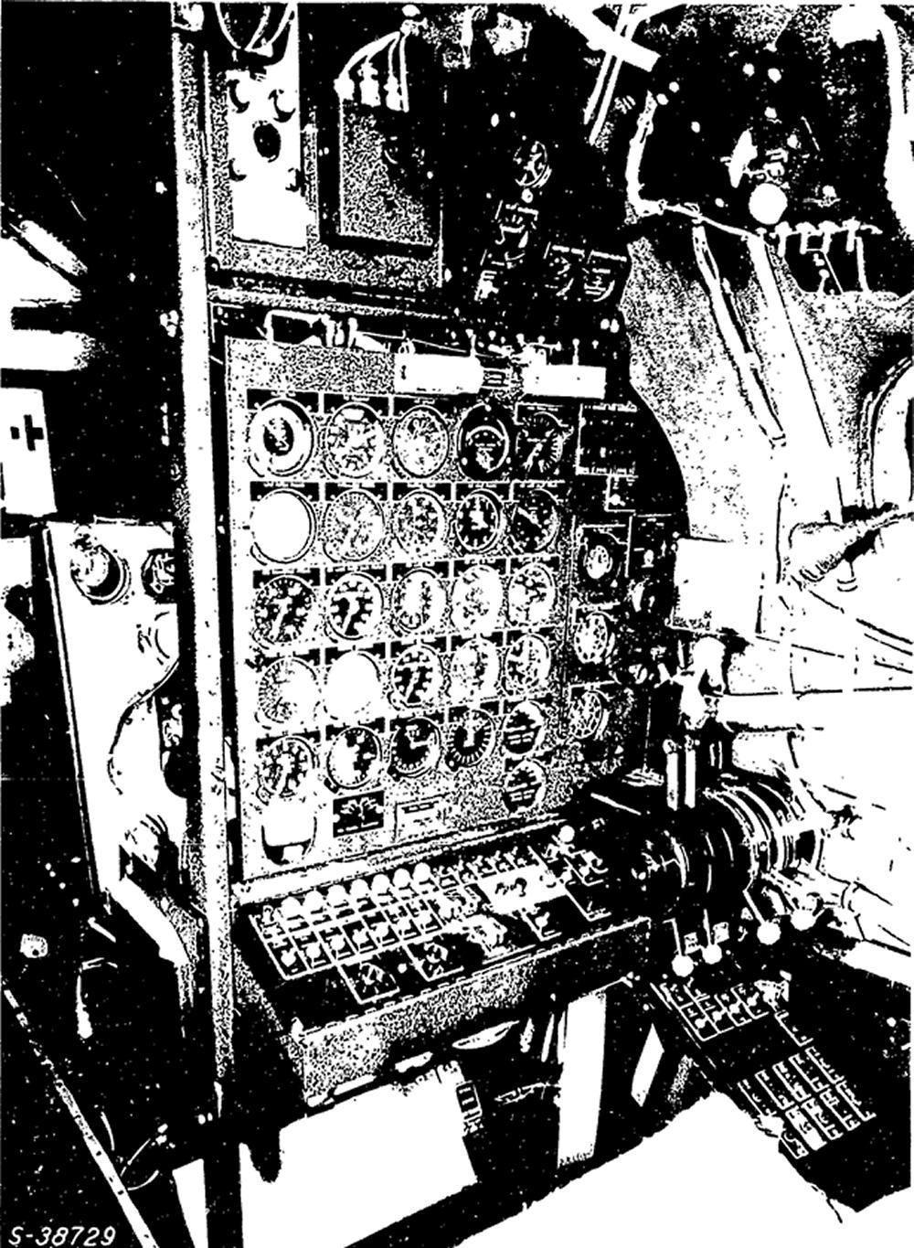
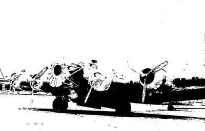
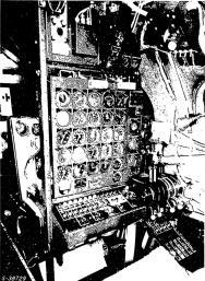
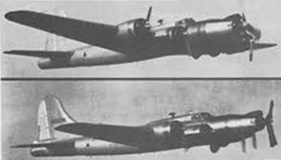
The Navy funded preparations for flight testing of the VC86260 in 1964 starting with the reconfiguration of a Boeing B-17G (Constructor number 8643; N5111N) to carry the T64-GE-1 engine (up to 2,675 hp) in the nose of the aircraft. (Figs. 18, 19) The cockpit was moved aft by several feet, a rugged tubular engine mount attached to the reinforced nose, and an engineer’s station for controlling the experimental propulsion system was built in the bomb bay. (Fig. 20) There were 56 individual engine, propeller, gearbox, and nacelle parameters measured.
The modified B-17 was first used to test a single rotation propeller 73EGB1 that utilized the SK56209 integral gearbox. Subsequent to the 73EGB1 flight trials, the SK56209 gearbox was modified further and used on the VC86260 flight program.
The specifics of the flight test program are too numerous to delineate in this article, but are available in the Flight Test document. Suffice it to say that torque levels, vibration, fluid flows, fluid pressures, RPMs, and temperatures were evaluated at selected speeds from ground taxi to 245 mph maximum indicated airspeed. Blades angles varied from -21° (reverse pitch) to 83° (feather). Rate of blade pitch change was between 11° and 16° per second. Feathering time by electrical means varied from 3 to 5 seconds, by mechanical means (emergency hand pumping?) was 10 to 25 seconds, unfeathering took 8 to 16 seconds, and reversing took only 1.5 seconds.
 |
 |
 |
 |
| Fig. 18. Poorly reproduced photograph of the modified B-17G flight test aircraft. The cockpit was moved aft several feet, the fore fuselage reinforced, and tubular engine mount and firewall dishpan installed. (Negative X-15587; Flight Test Report) |
Fig. 19. Close up of the modified B-17G flight test aircraft showing the tubular steel engine mount. Note the large white tubular exhaust duct exiting the center of the firewall and snaking downward and aft to discharge under the fuselage.(Negative X-15586; Flight Test Report) |
Fig. 20. Power plant test engineer position in the bomb bay of the B-17G aircraft. (Negative S-38729; Flight Test Report) |
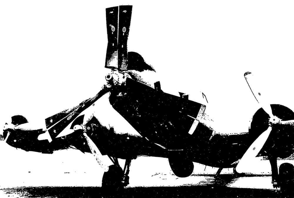
Fig. 21. Hamilton Standard variable camber propeller VC86260-5 installed on the General Electric T64 turboshaft mounted on the nose of the B-17G test aircraft. Note the square propeller blade tips and large blade cuffs. The propeller is 13 feet 6 inches in diameter. (Negative G-29217; Flight Test Report) |
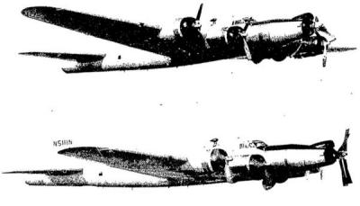
The fifty hours of flight testing of both propellers and the integral gearbox went very smoothly and without incident. On at least one occasion all four of the Wright R-1820 Cyclones were feathered while the T64 and VC prop alone pulled the B-17 through the air. The VC86260 flight program ran from 2 March 1966 to 10 May 1966. (Figs. 22, 23)
 |
 |
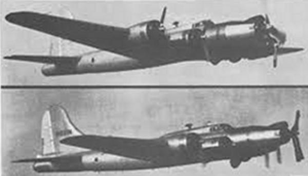
| Fig. 22. Composite of two poor quality photographs showing the VC propeller pulling the B-17G with the four piston engines feathered (top). The bottom photograph shows he VC propeller feathered in flight. At takeoff the four piston Wright Cyclone engines produced 4,800 horsepower total. (Negatives C-993, C-994; Flight Test Report) |
Fig. 23. Low resolution composite of two poor quality photographs showing the VC propeller pulling the B-17G with the four piston engines feathered (top). The bottom photograph shows he VC propeller feathered in flight. (Photo from Thrusting Forward) |
Summary quoted verbatim from the Flight Test Report:
“A 50 hour flight test was conducted on both the 73EGB1 and VC86260 propellers. These tests were conducted on the United Aircraft Corporation B-17G test bed aircraft which was removed from long time storage and reconditioned. A 73EGB1 gearbox was modified to a shaft configuration for use in the VC86260 propeller flight test. Development tests and a 50 hour engine PFRT (Preliminary Flight Rating Test) were conducted on this gearbox. Both test propellers and gearboxes were assembled primarily from hardware used in development testing programs on the 73EGB1 and VC86260 propellers. In general, both propellers performed satisfactorily during their respective tests.”
It is difficult to discern whether the variable camber propeller met the design and performance goals projected by Hamilton Standard. In a 1968 SAE article George Rosen states the variable camber propeller is particularly suited to high speed VTOL aircraft and that it offers little advantage at airspeeds below 0.4 Mach (approx. 294 mph @ 10,000 ft.). He further states that typical propellers designed for high static thrust are way oversized for high speed flight, intimating the value of the VC propeller.
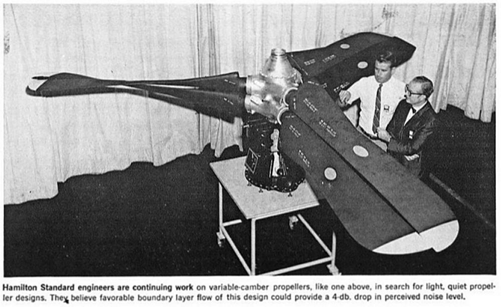
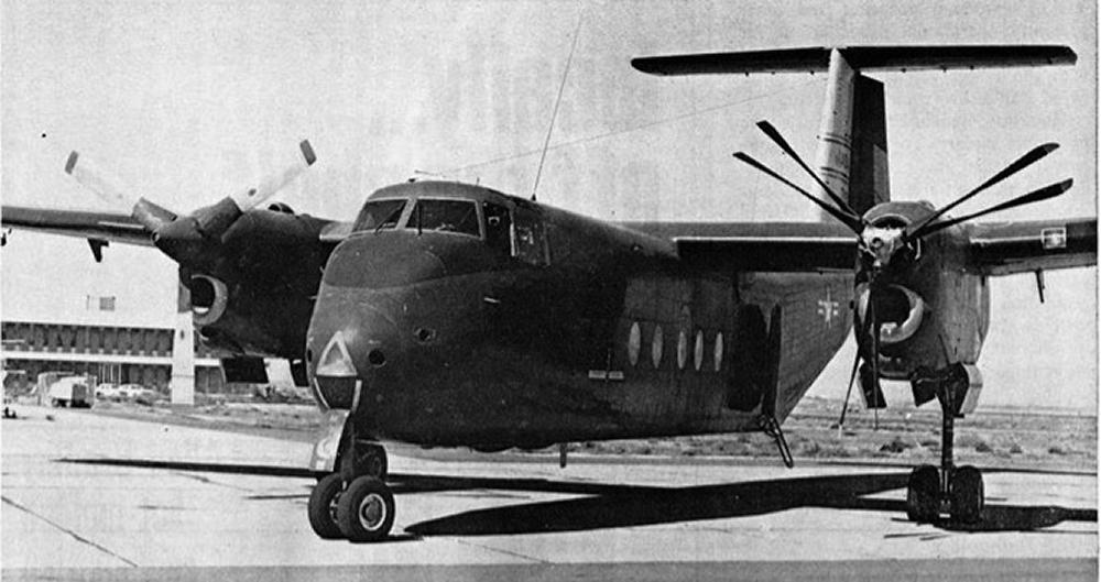
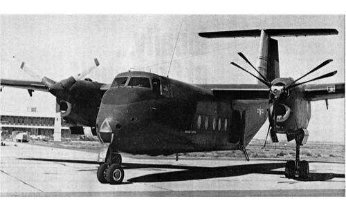
An article discussing approaches for reducing propeller noise printed in Aviation Week and Space Technology, 24 November 1969, shows a photograph of the round-tipped, six blade variable camber propeller with George Rosen stating the variable camber propeller is 3 to 4 decibels quieter than a comparable fixed camber propeller. (Fig. 24) The article also shows the variable camber propeller mounted on the port engine of a de Havilland DHC-5 Buffalo where it underwent static performance and taxi-testing, but apparently not flight. (Fig. 25) The production DHC-5D used the General Electric CT64-680-4 engine of 3,133 shaft horsepower driving a three bladed Hamilton Standard 63E60-25 propeller fourteen and a half feet in diameter.
The November 1969 article seems to be the end of the line for the Hamilton Standard VC propeller. Aeroproducts did research and built experimental propeller blades with a full length, hinged, controllable trailing edge flap, but that is topic for another time.
In reality, it was likely that the ever-quieter, increasingly-fuel-efficient high bypass turbofan jet engine was what killed the variable camber propeller. While the VC propeller remains an innovative technical marvel of limited historical relevance, for me, in model form, it is simply a wonderment to behold.
 |
 |
| Fig. 24. Six blade VC86260 propeller with integral gearbox. Note the blade cuffs and semi-rounded blade tips. (Aviation Week and Space Technology, 24 November 1969. page 56) |
Fig. 25. Six blade VC86260 propeller mounted on port side of de Havilland DHC-5 Buffalo. Aircraft was statically and taxi tested, but not flown. (Aviation Week and Space Technology, 24 November 1969; page 62) |
Variable Camber Excerpt from Advanced Propeller Concepts ... Developed Today
References
Thrusting Forward: A History of the Propeller, by George Rosen with Charles A. Azenis, published by the Hamilton Standard Division of United Technologies Corporation, 1984.
Variable Camber Blading, US Patent 2,982,361, granted May 2, 1961, to George Rosen, assignor to Untied Aircraft Corporation.
Two Part Pitch Changing Mechanism, US Patent 3,163,231, granted Dec. 29, 1964, to Phillip E. Barnes, Seppo J. Viikinsalo, and Richard B. Pitbladdo, assignors to Untied Aircraft Corporation.
“Propeller Integral Gearbox 73EGB1 and Propeller Variable Camber Model VC86260 Flight Test Report”, Report HSER 4076, Bureau of Naval Weapons Contracts NOw-64-0635-di and NOw-65-0533-d, 30 June 1966.
Variable Camber Prop Studied for VTOL by Barry Tully, Aviation Week, 15 August 1960, pages 98, 99, and 101.
Propeller Research Gains Emphasis by Michael L. Yaffee, Aviation Week and Space Technology, 24 November 1969, pages 56, 57,62,63,64.
Advertisement by United Aircraft International, Flight International, 30 April 1964, page 4.
Obituary for George Rosen, Hartford Courant, 16 June 2004.
"Unusual Propellers" by John Leonard, Rolls-Royce Heritage Trust Allison Branch Newsletter, December 2010.
"Next Generation V/STOL Propellers" by George Rosen and William M. Adamson, SAE Transactions Vol. 77, Sec. 2, paper 680248-68434, pages 893-905, 1968.
Advanced Propeller Concepts ... Developed Today (Windsor Locks, CT: Hamilton Standard, 1965).