Aeroproducts Model 606
The Aeroproducts Models A6441FN-606 and A6441FN-606A Propellers
Compiled by Kimble D. McCutcheon
Published 10 Sep 2023; Revised 6 Oct 2023
Aeroproducts Model 606 |
The hydraulically controlled turbo-propeller incorporates an integral hydraulic system that operates independently from all other systems, and maintains precise control during all operating conditions. Electrical power is supplied to the propeller for synchronizing, phase synchronizing, and ice control. These functions provide control refinement for passenger comfort and safety. The Model 606 is used in four-engine installations while the model 606A is used in twin-engine installations. Thanks are due the Rolls-Royce Heritage Trust, Allison Branch Archive and Tom Fey for making available Design Analysis, Turbo-Propeller Model A6441FN-606, 15 May 1957, from which this article is compiled. |
General Description
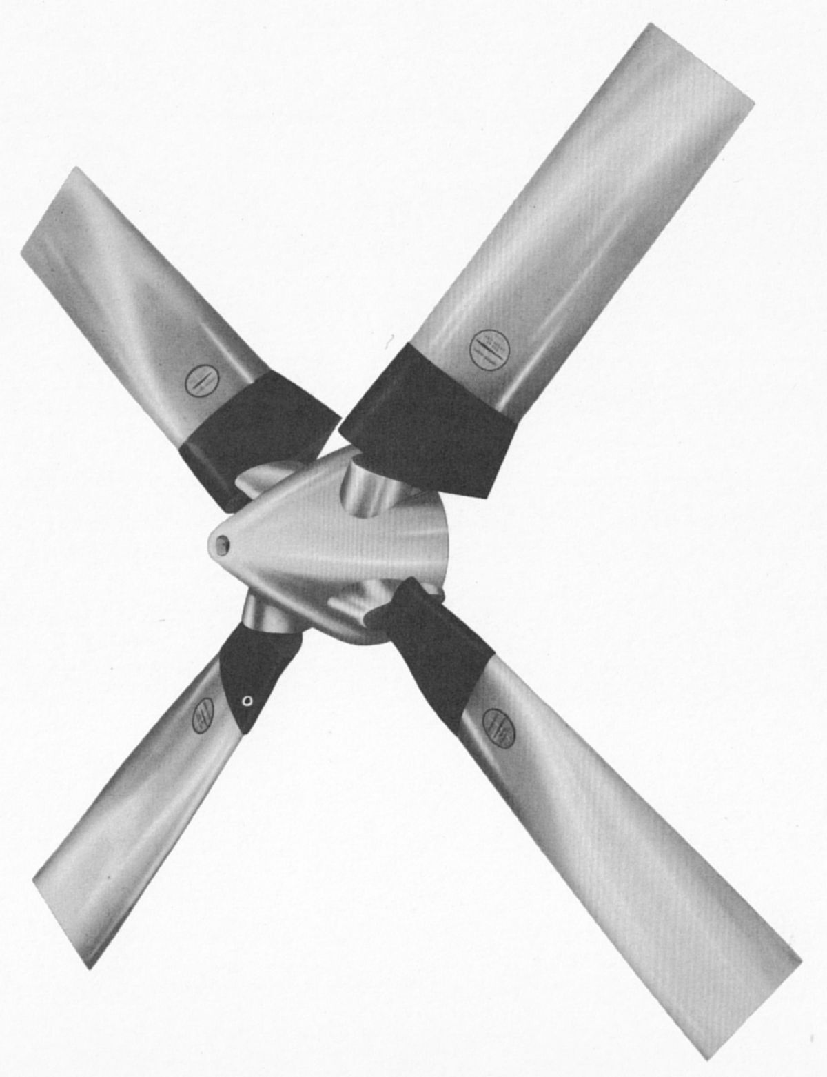
| Blades = 4 | Aerodynamic Blade Angles at 42" R Station |
| Diameter = 13.5 feet | Maximum reverse = -4° |
| Blade Chord = 18.5 inches | Ground idle = 1.5° |
| Governing Speed = 1,020 prop rpm (prpm) | Start = 7° |
| Installed Weight, Including Hydraulic Fluid and Grease = 1038 lb | Flight idle = 20° |
| 606 Accessories Not Mounted on Prop = 55.4 lb | Feather = 94.7°+0.2°, -0.1° |
| 606A Accessories Not Mounted on Prop = 25 lb | Beta Follow-Up at Takeoff = 31.5°+0.5°, -1.0° |
| Hydraulic Fluid = Aeroproducts Material Specification 1-40002 | Mechanical Low Pitch Stop = 18.25° - 18.50° |
| Hub Grease = Aeroproducts Material Specification 1-43002 | Hydraulic Low Pitch Stop = 20° |
Major Assemblies and Components
 |
| Assemblies |
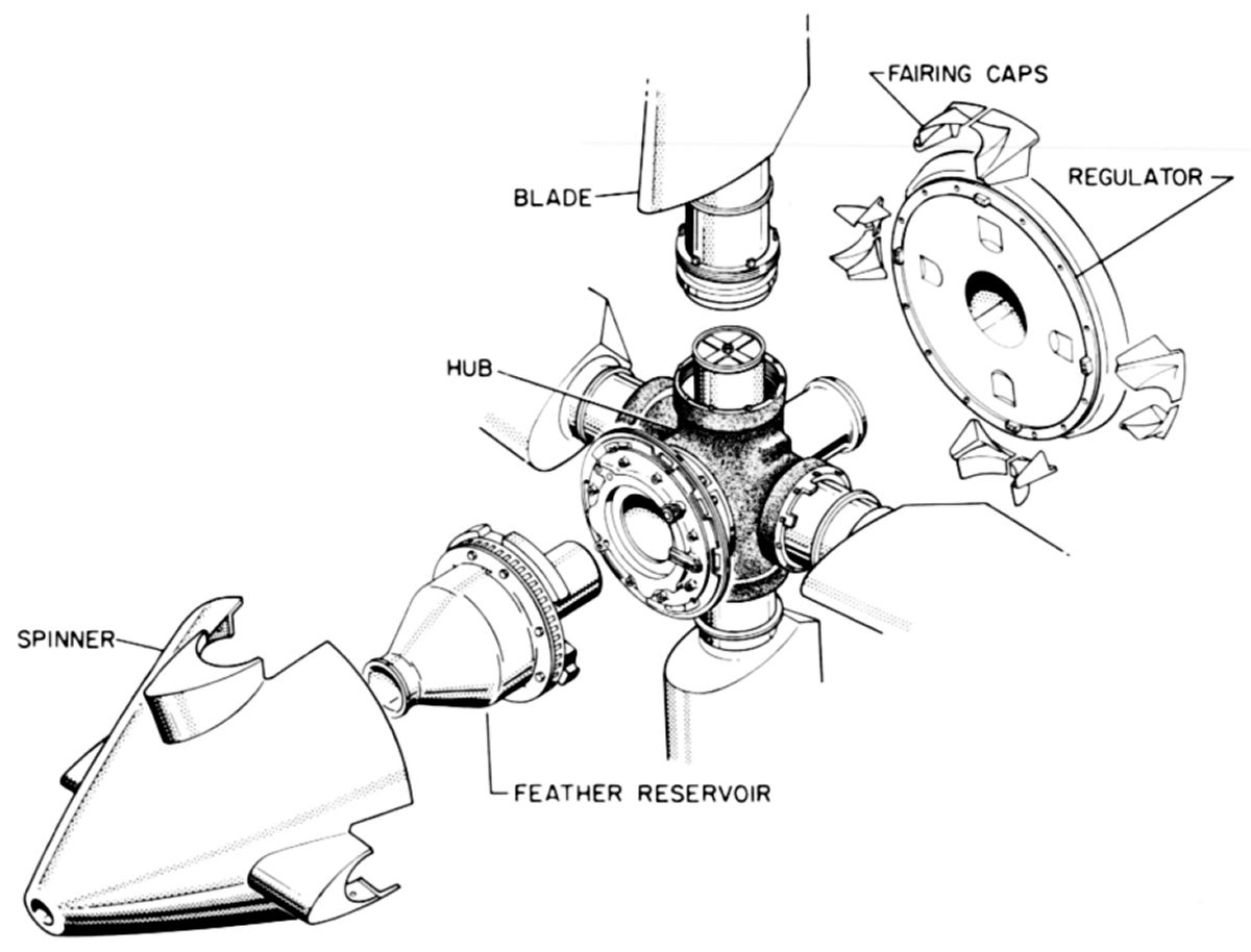
Five major assemblies mounted on the engine propeller shaft, plus the control components and assemblies mounted in the aircraft, comprise the 606 propeller. The major assemblies are hub, blades and retention, regulator, feather reservoir, and spinner. An engine-driven propeller alternator, electronic controls for synchronization and phase synchronization, ice control accessories, and necessary switches, relays, etc., complete the installation.
Hub Assembly
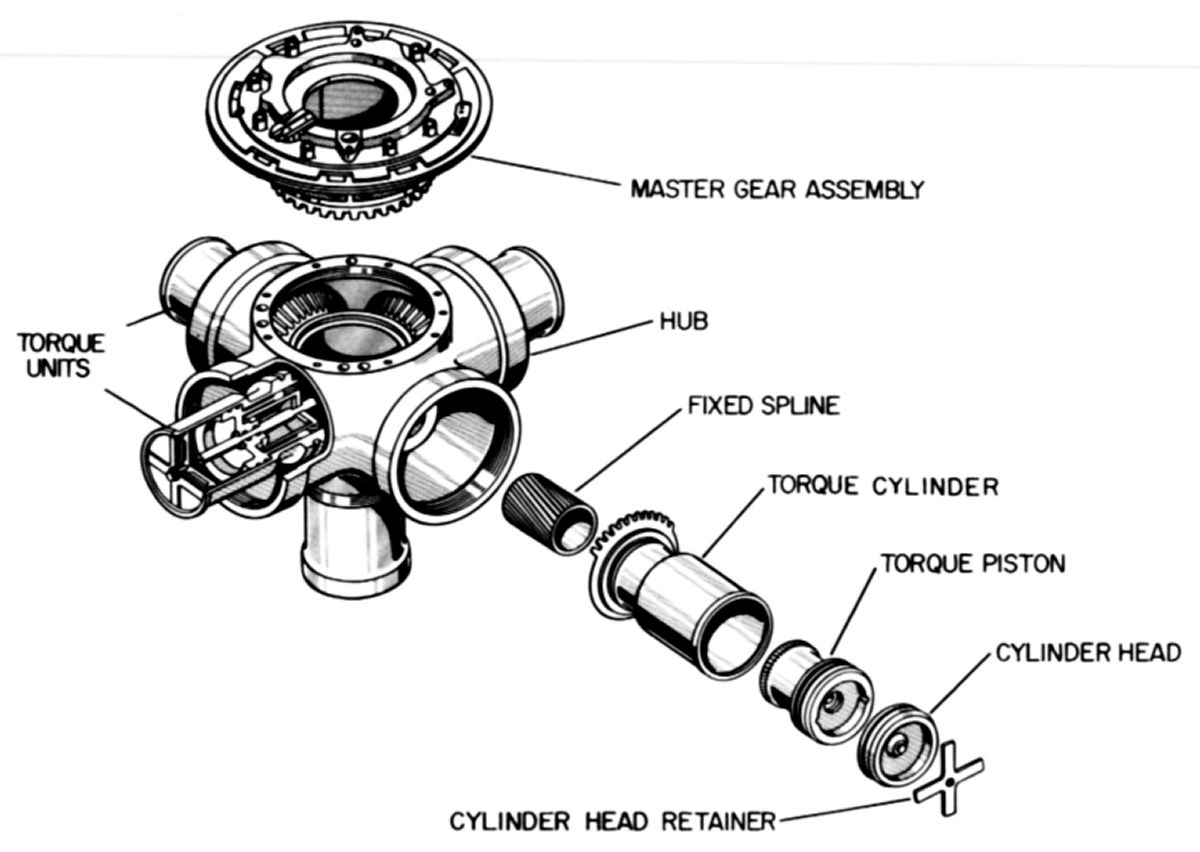 |
| Hub |
The hub assembly is the principal propeller structural member and consists of the hub, torque units, and master gear assembly. The hub, machined from a steel forging, provides mounting for the pitch control mechanisms and the sockets for blade retention. Splines and cone seats are machined on the hub inner diameter. The splines and cone seats ensure the hub is properly positioned on the propeller shaft. The hub contains hydraulic fluid passages that deliver hydraulic fluid, under pressure, from the regulator to the torque units, master gear assembly, and feather reservoir. The hub is shot-peened to increase its fatigue life, and is cadmium plated to prevent surface corrosion. Each hub socket contains a torque unit consisting of a fixed spline, a piston, and a cylinder. A retaining bolt, which secures the fixed spline to the hub, incorporates a tube that transfers fluid to the outboard or decrease pitch piston side. A port in the fixed spline base transfers fluid to the inboard or increase pitch piston side. Helical splines, machined on the torque unit components, convert linear piston motion to cylinder rotation, which is transmitted to the blade through an indexing ring and matching splines on the cylinder and in the blade root.
 |
| Master Gear |
The master gear assembly consists of a housing, master gear, mechanical low pitch stop, mechanical pitch lock, air shutoff, and feedback mechanism parts. The housing is splined and bolted to the hub front face and provides the feather reservoir mounting surface. The master gear coordinates torque unit movement so that all blades have the same aerodynamic blade angle. Splined to the housing are the parts that comprise the mechanical low pitch stop (MLPS) and the mechanical pitch lock. Feedback mechanism parts, actuated by blade angle changes, operate the cooling air shutoff mechanism, Beta light switch, and feedback shaft that mechanically positions a part of the hydraulic governor's control linkage. As the blade angle approaches the feathered position, the master gear assembly feedback mechanism drives the air shutoff shutter to its closed position. The shutter begins to move toward closed at 60° blade angle, and when the blade angle reaches approximately 75°, all air flow through the spinner is shut off.
The Beta light switch controls the cockpit Beta light circuit. When the blade angle is below 18.5°, the Beta light switch is closed by the master gear assembly feedback mechanism, illuminating the Beta light to indicate that the propeller is operating in the Beta range. At blade angles above 18.5°, the Beta light switch opens and the Beta light extinguishes, indicting that the propeller is not operating in the Beta range.
Blade and Retention Assemblies
 |
 |
|
| Blade and Retention Scheme | ||
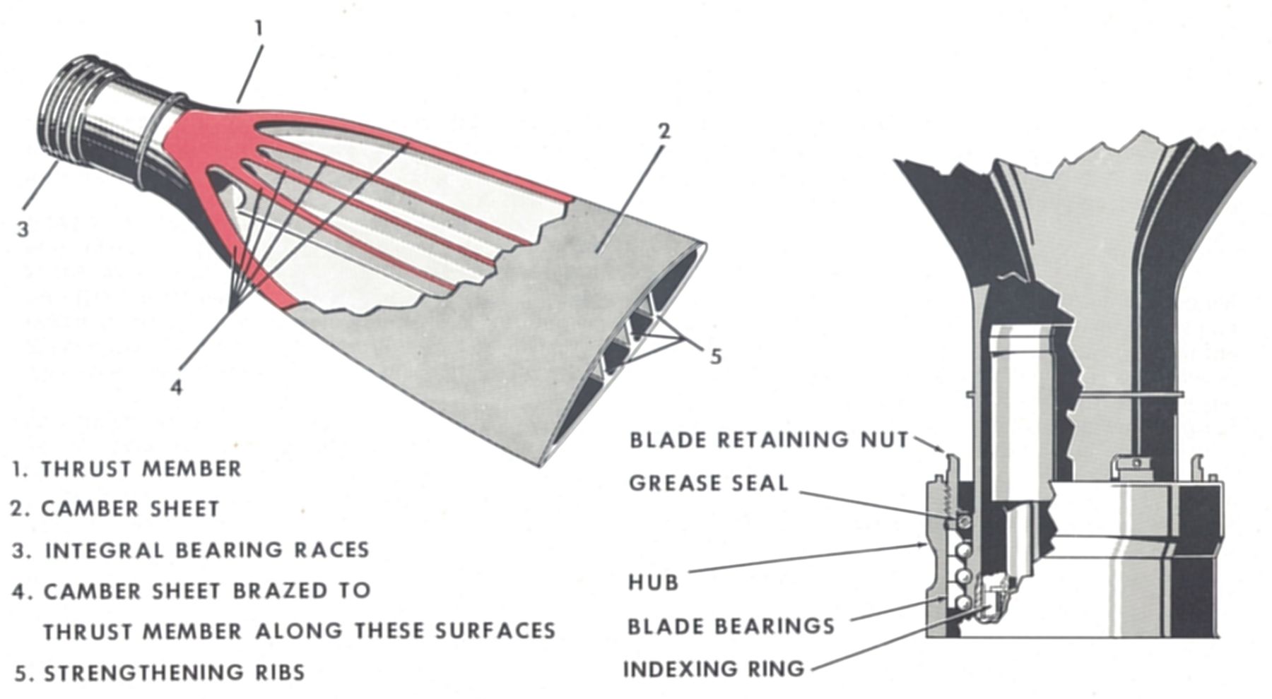
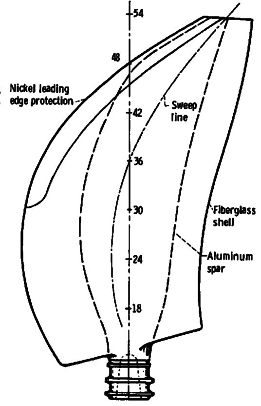
Each hollow steel propeller blade is made by joining a thrust member and a camber sheet. The thrust member, including the root section, three longitudinal strengthening ribs, and leading and trailing edge reinforcement, is machined and hand-ground from an alloy steel forging. A forged camber sheet is fitted to the thrust member, with each being metalized with a copper alloy at their respective mating surfaces. These are roll-welded from the 54" station outboard to the tip on the leading edge, and the two parts are joined by brazing in an electric furnace at 2,200°F. Prior to brazing, the thrust member and camber sheet interior surfaces are ground and polished for maximum fatigue strength. The blade is given an external hand-ground finish for final contour.
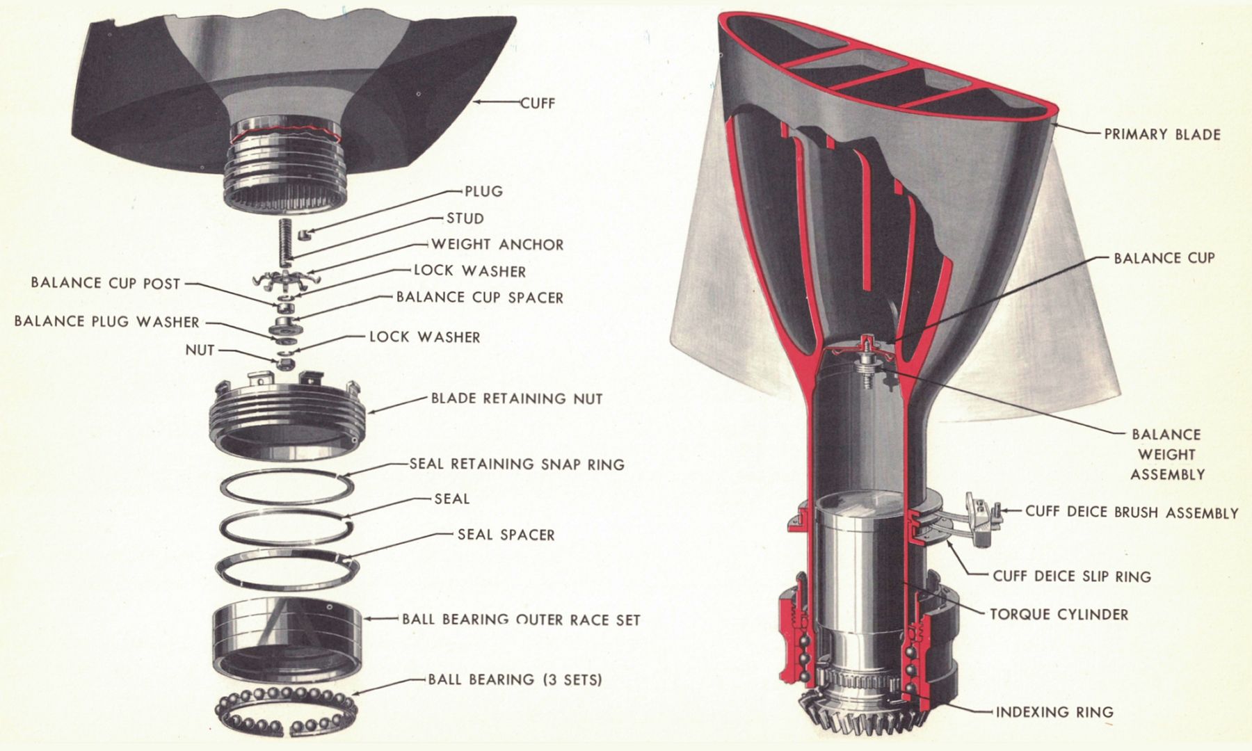
The inner races on the blade root are precision ground, and form a part of the retention assembly. In the blade root inside diameter are 100 broached splines that mate with the blade indexing ring that has 100 splines on its outside diameter. The blade interior is treated with corrosion resistant paint. A balance cup, inserted into the blade root, also serves to seal the blade portion that has received the corrosion resistant treatment. The sealed area is purged with dry nitrogen through a small plug in the balance cup, preventing any chance of internal blade corrosion. The external blade surfaces are protected from surface corrosion by zinc plating and a yellow ano-zinc dip treatment. In addition, the blades tips are dull-chrome plated in the high abrasion areas.
The blade root end incorporates a molded plastic cuff that streamlines the blade and improves engine air inlet recovery, which increases ground operating time through better cooling. The blade cuff is made of plastic foam, with an external fiberglass sheath forming a light but sturdy cuff that includes an etched stainless steel and neoprene rubber deice heating element, and lead wires that are cemented to the cuff leading edge, thus providing for ice removal. The lead wires are attached to the blade deice slip ring assembly, which is clamped on the external blade root. The molded plastic cuff is easily repaired if damaged. The blade weight and mass balance are matched with a master weight by the blade balance weight assembly, making the blades interchangeable.
The blade is painted with clear lacquer. Blade number, serial number, and aerodynamic classification are stenciled on the camber side. An Aeroproducts decal is also placed on the blade camber side to be read from the tip. Black lines painted on the thrust side locate the 42" station for measuring blade angle. Aeroproducts 606 blades are guaranteed for 10,000 hours, at which time they will be inspected and if serviceable, will be guaranteed for an additional 5,000 hours.
 |
 |
 |
| Model 606 Blade Details | Activity Factor | Propfan SR-7L Planform |
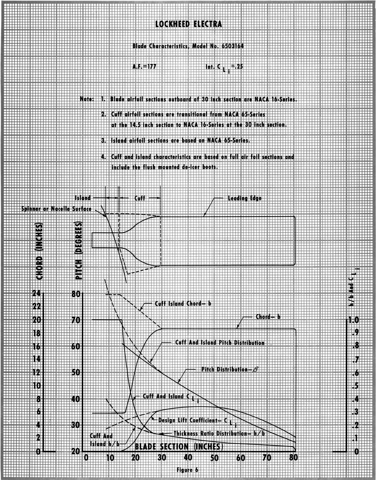
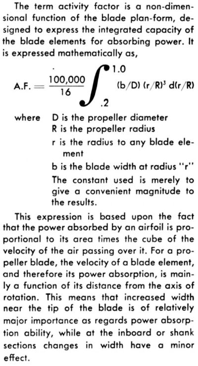
Model A6441FN-606 and -606A blades are noteworthy for their wide, nearly constant chord, which results in a relatively high activity factor of 177. Propeller historian Tom Fey suggests that Aeroproducts and Curtiss hollow-steel blade construction using high-strength forged elements resulted in very stiff blades that helped prevent flutter at the thin, broad tips. Activity factor (A.F.) is a non-dimensional value that reflects a blade's ability to absorb power; the bigger the number, the better. Blades with wide, constant chord planforms or wide tip chords (like the 606) tend to have higher A.F.s than tapered blades. By way of comparison, the McCauley 1C172 propeller used on many Cessna 172s has an A.F. of 104. The legacy Hamilton Standard 54H60 turbopropeller blades on older Lockheed C-130s and P-3s have an A.F. of 162. That SR-7L propfan blade gets its high 228 A.F. from the relative extreme width in the blade center.
Each retention assembly consists of a blade retaining nut, seal-retaining snap ring, O-ring grease seal, seal spacer (two halves), three outer races, and three sets of ball bearings in Teflon cages. The blade retaining nut is a machined forging, incorporating a lip around the inside diameter as a backing for the seal snap ring. Threads are machined on the blade retaining nut outside diameter for attachment to the hub socket, and a series of tangs are located around the outboard edge for attaching the blade nut lock and required balance weights.
The retention assembly outer races are duplex ground and precision fitted with bearings and Teflon cages to obtain a blade retention with maximum service life and optimum load distribution. The ball bearing outer races are ground on their respective inboard edges to fit a specific blade, and are not interchangeable. These three races carry the blade serial number to which they have been ground, and are numbered one through three, with number three toward the blade tip. A wide etched arrow pointing toward the blade tip across all three bearing races provides the means to check proper position. This procedure assures that all three bearing sets will carry equal loads. This retention normally carries a centrifugal load of approximately 40 tons, and is capable of carrying as high as 80 tons without bearing brinelling.
Regulator Assembly
 |
| Regulator Assembly |
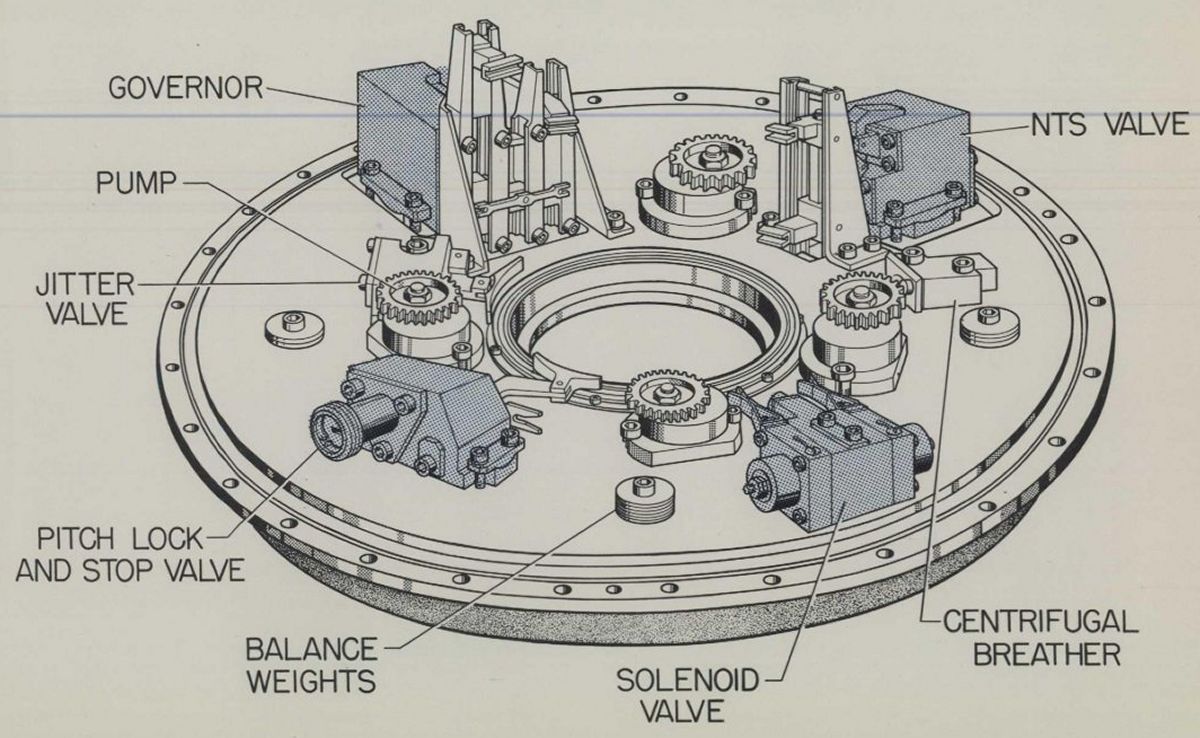
The regulator assembly, mounted on the hub rear, consists of a cover and housing assembly, adapter assembly, pumps, valves, and hydraulic fluid required to provide controlled flow to the hub pitch change and control mechanisms. These parts, except for portions of the adapter assembly, are contained in the regulator cover and housing. The regulator assembly, except for the adapter assembly, rotates with the propeller. When the propeller assembly is placed on the propeller shaft, two engine-mounted adapter stops engage with tangs on the adapter assembly. This prevents rotation of the adapter assembly when the propeller rotates. The adapter assembly is supported by two ball bearing assemblies in the regulator. Seals, located in the regulator cover and housing, contact the adapter assembly to retain the hydraulic fluid. The adapter assembly consists of the mechanical control components that are coupled to the valves and pump power gear in the regulator and the accessory plate outside the regulator. Mechanical control movements from the engine, or cockpit, are transferred into the regulator to control the hydraulic operation of the propeller. This mechanical control is accomplished by movement of the propeller condition control lever or negative torque sensor (NTS) feather lever. The accessory plate, which is attached to the adapter assembly, supports the brush block assemblies, the rotary actuator, a solenoid stop, and adapter stop tangs. Two brush block assemblies are provided, one for ice control and the other for solenoid valve control, Beta light, and feather pump. Electrical power is supplied to and conducted through the brush block assemblies to the slip rings mounted on the regulator cover. Electrical power is also supplied to the rotary actuator.
 |
| Feather Reservoir Assembly |
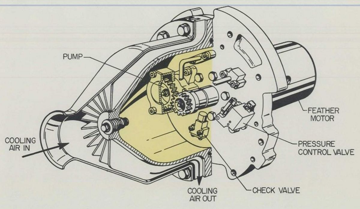
Feather Reservoir Assembly
The feather reservoir assembly, installed on the hub forward face, consists of a feather motor, pump, pressure control valve, check valve, and filler check valve mounted in a housing and cover assembly. A sufficient quantity of hydraulic fluid is available in the feather reservoir to accomplish feathering in the event the regulator hydraulic fluid supply is depleted. This assembly also supplies hydraulic flow for stationary pitch change operation, and for completion of the feathering cycle. Air is admitted through the spinner nose and directed over the cover for cooling the hydraulic fluid.
Spinner Assembly
The spinner is a one-piece aluminum alloy assembly that provides the streamlined airflow past the blade cuffs and over the feather reservoir, hub, and regulator. The spinner is positioned and supported by dowels on the regulator spinner mounting ring, and retained to the feather reservoir by a nut in the spinner nose. Spray mat type ice control circuits are on the external spinner surface.
Mechanical Control System
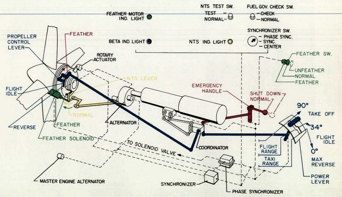 |
| Mechanical Control System |
Two linkage systems convey this information to the propeller. One system is attached to the propeller condition control lever, and the other to the propeller NTS-feather lever.
The power lever and emergency handle are each connected by aircraft linkage to the engine co-ordinator. Linkage from the co-ordinator is attached to the propeller condition control lever. The co-ordinator contains a cam assembly called a discriminator that permits the power lever to control the linkage to the propeller if the emergency handle is in its normal (pushed in) position. The discriminator permits the emergency handle to override power lever action in positioning the propeller linkage any time the emergency handle is pulled. The propeller condition control lever thus informs the propeller regulator of the power lever and emergency handle positions.
The feather solenoid and the engine NTS system are connected to the NTS linkage, which is attached to the propeller NTS-feather lever. The NTS-feather lever informs the propeller regulator of feather solenoid and NTS system requirements on the hydraulic system. Each power lever has five positions indicated on the pedestal - maximum reverse, ground idle, start, flight idle, and take-off. These power settings relate to the engine co-ordinator pointer as follows:
| Power Lever Setting | Co-ordinator Angle |
| Maximum Reverse | 0° |
| Ground Idle | 9° |
| Start | 15° - 20° |
| Flight Idle | 34° |
| Take-off | 90° |
Any reference made to power setting in degrees relates to the coordinator pointer indication. Power settings in degrees are used in control system schedules and for rigging. The power lever is the "lift to Beta" type. In order to get from the "flight range" into the "taxi range," the power lever must be lifted at the flight idle setting. To get from the "taxi range" into the "flight range," the power lever must be moved down at the flight idle setting. The emergency handle provides the means of shutting down an engine by a single action. Pulling the emergency handle will actuate mechanical linkage and electrical circuits to effect an electrical and a mechanical engine shutdown. The feather solenoid, secured to the reduction gear assembly, is mechanically attached to the engine NTS linkage. When the feather solenoid is energized, it actuates the engine NTS linkage, which results in the propeller NTS-feather lever being moved to the feather position. Thus, the propeller is signaled to feather if the propeller NTS system is not blocked out due to power lever setting. (Propeller NTS system is blocked out below 21° co-ordinator.) The reduction gear NTS system is also mechanically attached to the engine NTS linkage. If negative torque is from -300 to -420 shp, the NTS system actuates the engine NTS linkage which results in the propeller NTS-feather lever being moved into the feather position. Thus, the propeller is signaled to feather. As the propeller blade angle increases, the negative torque produced by the propeller decreases to a point at which the reduction gear NTS system no longer is actuated. The NTS system returns to the NORMAL position which removes the feather signal to the propeller. The propeller hydraulic governor then regains control of the propeller, and it decreases blade angle. If the negative torque again actuates the NTS system, the above cycle repeats itself. The cycling of the NTS system from the actuated to the non-actuated position is called "NTSing". If "NTSing" occurs during an approach with low power settings, a slight advance of the power lever will stop the "NTSing". If "NTSing" is a result of an engine failure, the "NTSing" can be stopped by feathering the propeller.
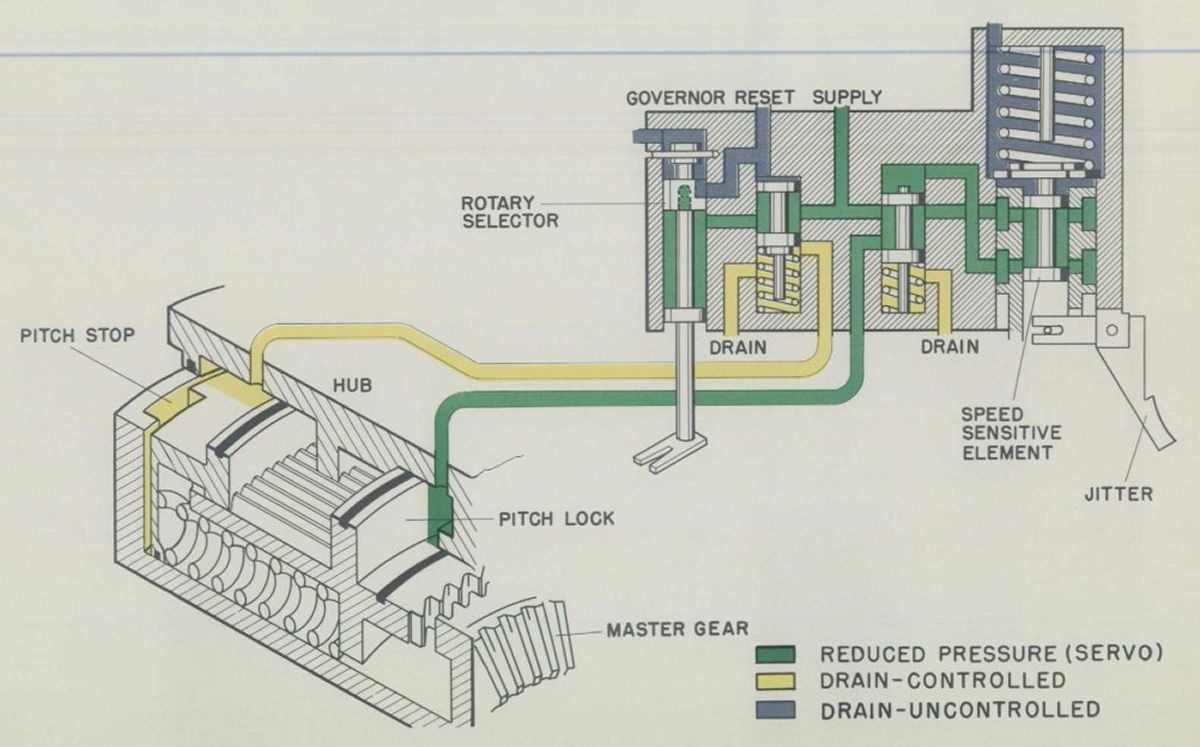
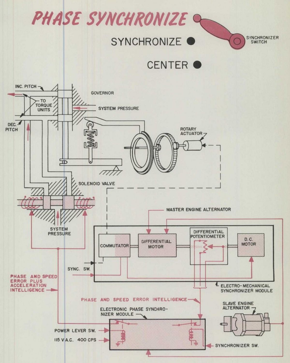
Hydraulic System
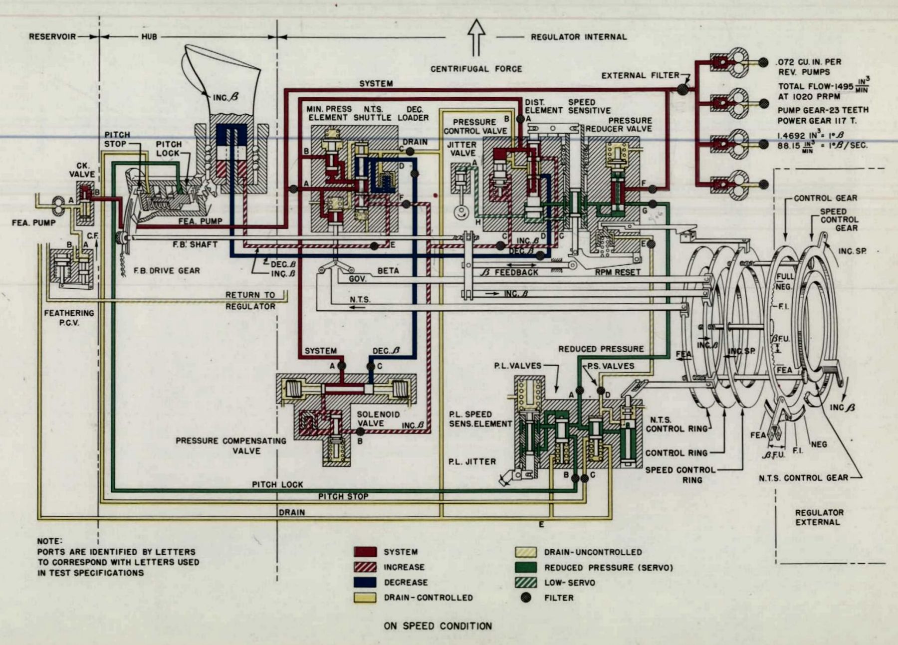 |
| Hydraulic System |
The propeller will function satisfactorily when fluid conforming to Aeroproducts Material Specification 1-40002 is used in the hydraulic system. Approximately three gallons of hydraulic fluid are required per propeller. This fluid is contained in the regulator reservoir and the feather reservoir. A visual oil level sight gage is provided for quick, easy hydraulic fluid level check. The propeller does not consume hydraulic fluid. However, if replenishment is required, hydraulic fluid may be added through a filler tube and check valve at the front of the feather reservoir without removing the spinner. The use of a pressure filling device is recommended, for this provides rapid filling and assures the use of only clean filtered hydraulic fluid.
Any hydraulic fluid that drains into the regulator is called uncontrolled drain. Hydraulic fluid that drains into the feather reservoir is called controlled drain. Except for a small amount of internal leakage, all fluid pumped by the hydraulic pumps is directed to controlled drain. The air flow over the exterior of the feather reservoir cools the hydraulic fluid. The feather reservoir overflows the cooled fluid back into the regulator reservoir where the pumps again pick it up for recirculation. Thus, the controlled drain provides for cooling of the hydraulic fluid, and keeps the feather reservoir full. In the event of a regulator hydraulic component malfunction that requires feathering the propeller, the feather reservoir and pump can supply the hydraulic fluid flow required for feathering. Four gear-driven hydraulic pumps, located in the propeller regulator, are driven only when the propeller is rotating. Their volume output is a function of rpm. Thus, if a propeller is signaled to feather during flight, the output of these pumps decreases as rpm decreases. An auxiliary source of hydraulic pressure is required to completely feather the propeller. If an auxiliary source of hydraulic pressure were not available, the propeller would not completely feather, but would continue to rotate at a high blade angle with low rpm and low drag. The auxiliary source of hydraulic pressure is provided by an electrically driven hydraulic pump. Operation of this pump is required for unfeathering, feathering, and hydraulic system static checks.
Safety Features
Due to the characteristics of prop-jet power plants wherein high drag forces are associated with either engine or propeller failure, certain safety devices must be incorporated in the turbo-propeller to assure safe operation. These safety devices reduce the asymmetric thrust to values compatible with airframe structural limitation and controllability. The following safety devices are included in the model A6441 FN-606 and A6441 FN-606A propellers.
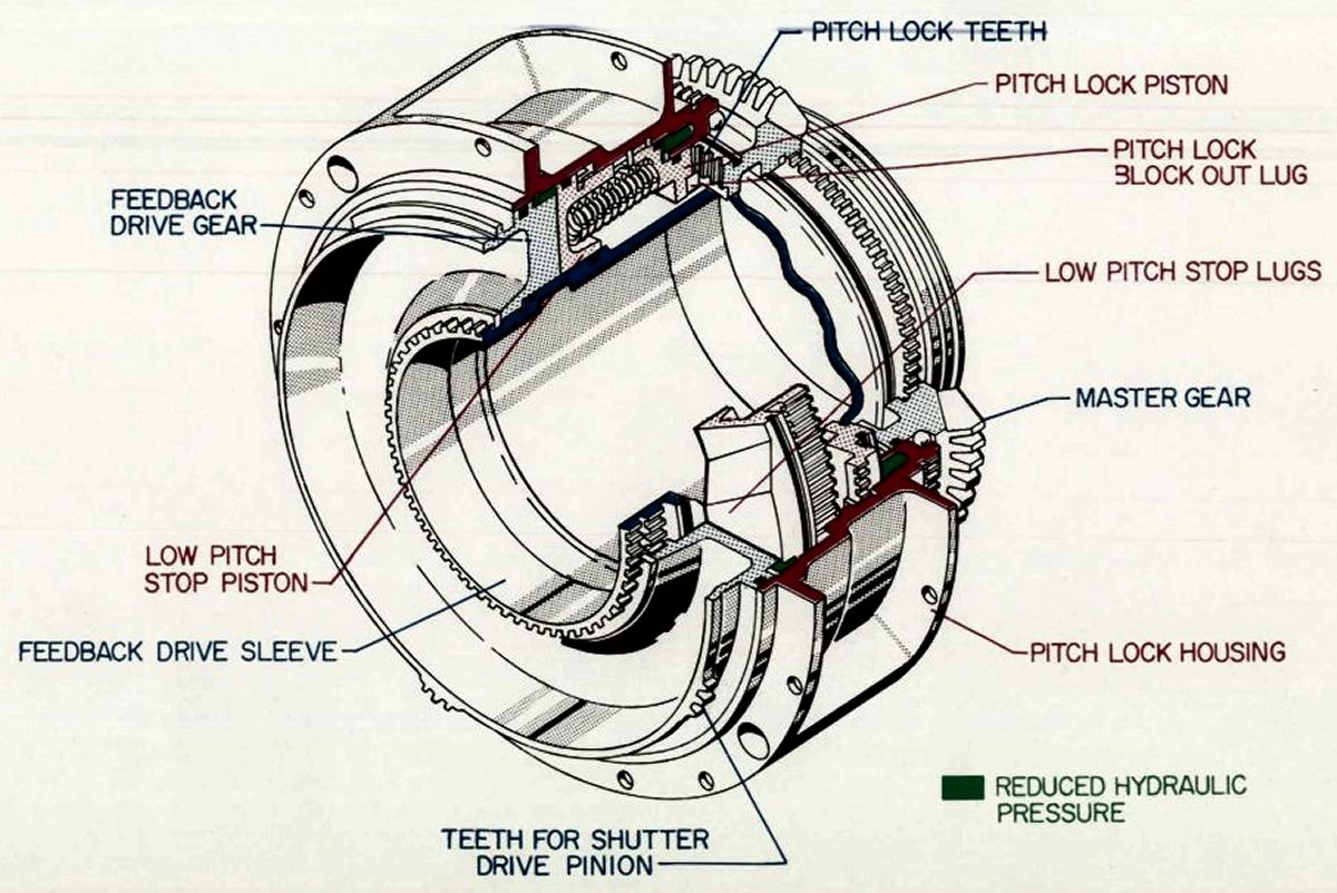
The pitch lock mechanism is a speed-sensitive device designed to protect against flattening blade angle pitch-down in the event of a propeller control system malfunction, which results in an overspeed condition. Pitch lock protection is needed only during governing range operation. Therefore, pitch lock is blocked out below 28° co-ordinator power settings, below 21.5° blade angle, or above 73.5° blade angle.
The mechanical low pitch stop (MLPS) prevents inadvertent blade transition into the Beta range during flight if the propeller control system malfunctions. The MLPS, with a setting of 18.25° to 18.5° blade angle, backs up the normal hydraulic low pitch stops.
The hydraulic low pitch stop (HLPS) prevents the propeller hydraulic governor from decreasing the blade angle into the Beta range during governing operation. The HLPS has a 20° blade angle setting from 30° to 68° co-ordinator. From 68° to 90°co-ordinator, HLPS is scheduled from 20° to approximately 31.5° blade angle. This scheduling of the HLPS is called Beta follow-up.
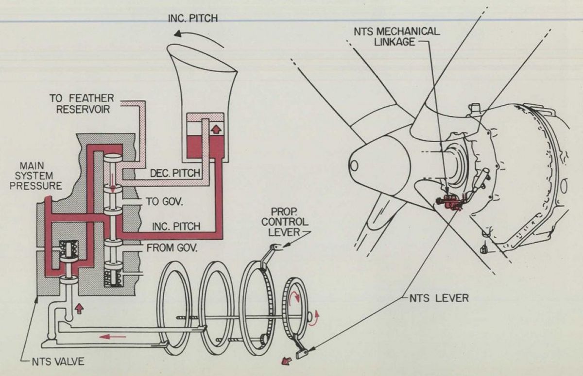
The negative torque signal (NTS) system functions at a specified torque (-300 to -420 shp) when the propeller tends to drive the engine due to lean fuel schedules at flight idle power settings, air gusts, loss of engine power, temporary fuel interruptions, or similar conditions. The NTS control system is incorporated in the engine reduction gear assembly. If negative torque exceeds the setting of the NTS control system, linkage to the propeller is actuated. The propeller responds to this by increasing blade angle as necessary to limit the negative propeller shaft horsepower. The NTS system within the propeller is blocked out below 21° to 24° co-ordinator power setting.
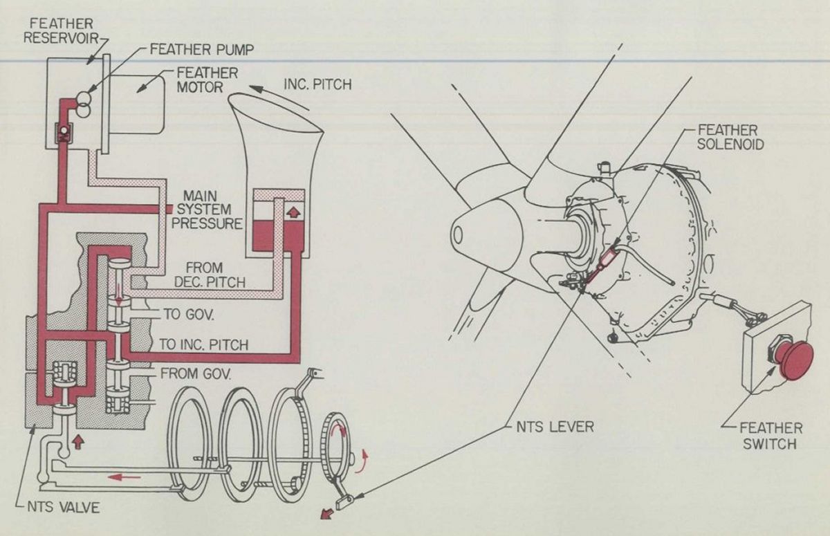
Manual feather is accomplished by depressing the feather button in the cockpit. When this is done, the propeller is signaled to feather by the feather solenoid, which causes the electric feather pump motor to be energized by a timer for approximately sixty seconds, and fuel flow is stopped via an electrical fuel cutoff actuator on the engine. Thus, the propeller will feather and the engine will stop running when the feather button is depressed. If this button is depressed when operating below a 21° to 24° co-ordinator power setting, fuel flow will be stopped, but the propeller will not feather due to the propeller NTS system being blocked out of operation.
The auto feather control system, incorporated in the engine reduction gear assembly, is disabled whenever the propeller thrust is greater than +500 lb. When propeller thrust is less than +500 lb, the auto feather control system will activate if the auto feather system is armed. The arming circuit of any given engine auto feather system includes several switches in series with each other. These switches are: a cockpit manually positioned switch, a 75° co-ordinator power lever switch, and necessary feather button switches. On a four-engine installation, an engine auto feather circuit is armed by a switch in each of the other engine feather buttons. On a two-engine installation, feather circuit is armed by a switch in the opposite engine feather button. If an auto feathering occurs, the feather button will be pulled into its feather position by a pull-in coil, which results in this button being moved exactly as with a manual feather.
Emergency feathering is accomplished by manually pulling the emergency handle. When this handle is pulled, switches are tripped and mechanical linkage is moved, which signals the propeller to feather and fuel flow to stop. The switches control electrical circuits that pull the feather button into its feather position via a pull-in coil. Thus, pulling the emergency handle results in engine shutdown electrically and mechanically. Emergency feathering can be accomplished under any condition of the engine operation regardless of the power setting.
The solenoid stop prevents a loose or disconnected condition control lever from entering the Beta range inadvertently, and from scheduling low blade angles which would cause excessive drag during flight.
 |
 |
 |
 |
| Pitch Lock, Low Pitch Stop | NTS Operation | Normal and Auto Feather | Emergency Feather |
Synchronizing and Phase Synchronizing
 |
 |
 |
| Syncronization Functions | ||
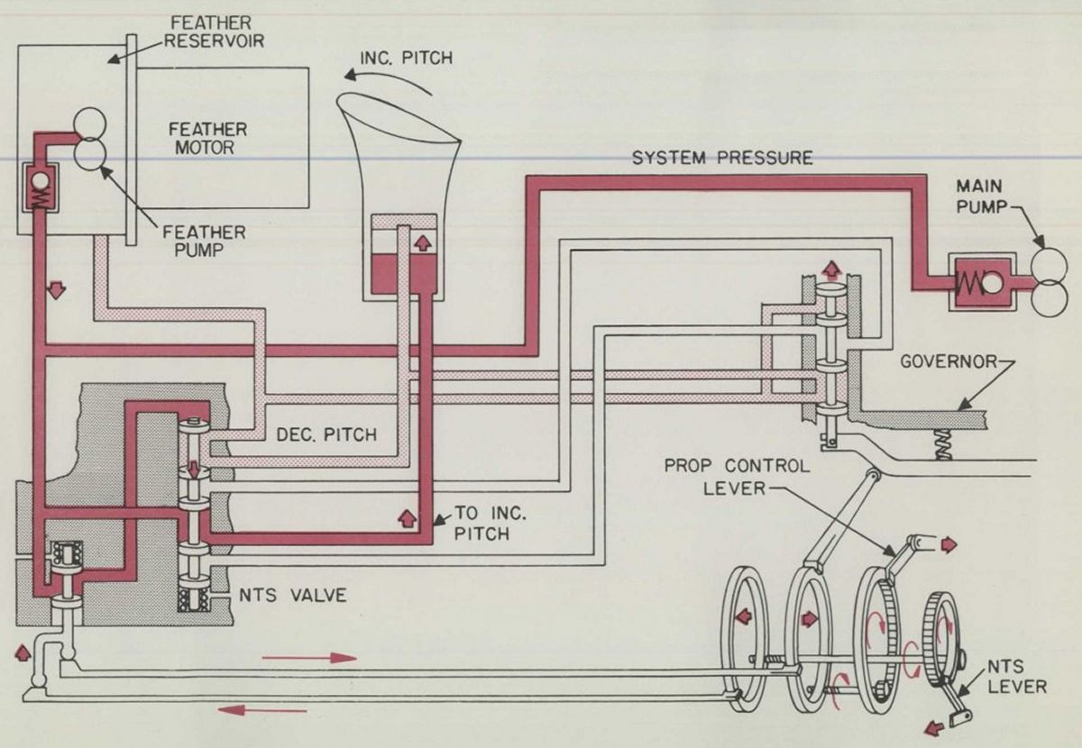
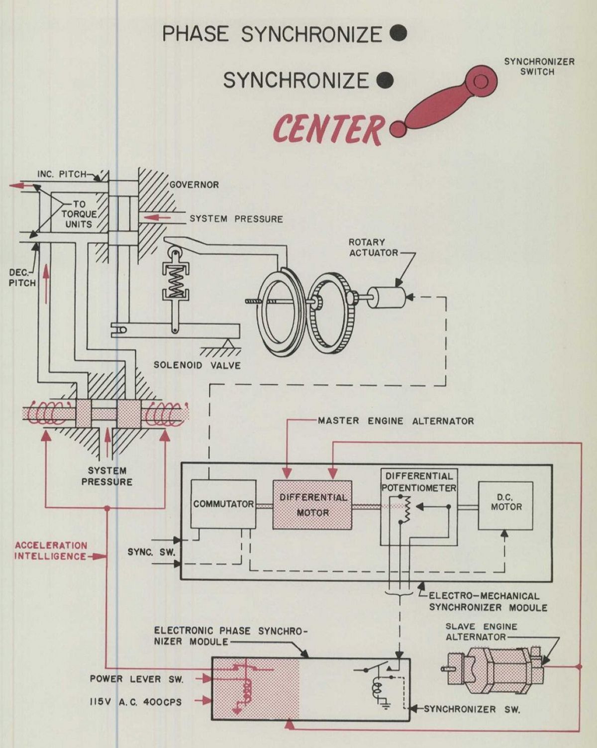
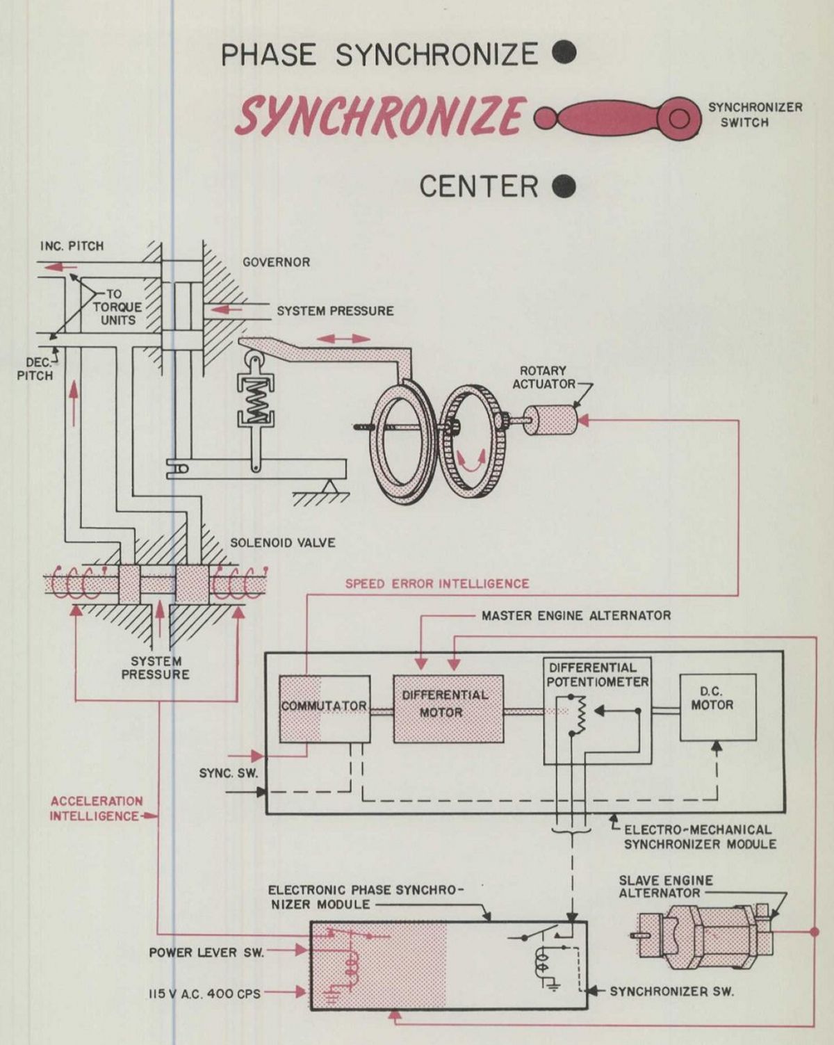
Five major components comprise the synchronizing and phase synchronizing systems: propeller alternator, rotary actuator, solenoid valve, electronic synchronizer module, and electronic phase synchronizer module. These components affect hydraulic system operation by reference to four factors:
K1 = Speed Error, Hydraulic - Normal propeller governing is obtained by means of a hydromechanical speed sensitive governor in the regulator. This governor, utilizing the K1 factor, provides satisfactory stability for all normal operation. No external accessories are required for K 1 operation.
K2 = Acceleration Sensitivity - To obtain optimum stability, it is necessary to use a control factor that is proportional to engine acceleration. Acceleration information, the K2 factor, is obtained from the engine-driven propeller alternator and the electronic circuits in the phase synchronizer module. The resulting voltage is used to power the solenoid valve in the regulator. Since governors are speed sensitive devices, some rpm variation (± 25 engine rpm) is to be expected when only K1 is utilized. The solenoid valve biases or trims the hydraulic governor fluid flow as required to quicken the off-speed recovery by dampening out any over-correction made by the hydraulic governor.
K3 = Trim Rate of Change on the Hydraulic Governor with respect to speed error - The K3 factor synchronizing function requires that the slave propeller governing rpm be reset to the master propeller governing rpm. This is accomplished by the slave and master propeller alternators sending speed information to the slave synchronizer module, which compares the slave speed to the master and pulses the slave rotary actuator accordingly. The rotary actuator, when pulsed, actuates the necessary mechanical controls to effect a governing rpm change on the slave propeller. When the slave propeller rpm equals the master propeller rpm, the propellers are said to be synchronized.
K4 = Trim Rate of Change on the Hydraulic Governor with respect to phase error - The phase synchronizing function, K4 factor, establishes the proper phase relationship by resetting the slave governor at a constant rate whenever the propellers are not at the optimum phase angle. This is accomplished by the slave and master propeller alternators sending phase angle information to the slave synchronizer module. The synchronizer module sends the phase error information to the slave phase synchronizer module, which converts this phase error information into the proper K4 signal voltage. This control voltage is mixed with the K2 voltage already present. The result is that solenoid valve is pulsed such that it biases or trims the hydraulic governor fluid flow for effective reset action to provide the optimum phase relationship between the slave and master propellers. Aircraft flight testing may indicate that the noise level could be reduced by changing the phase relationship between a blade on a slave propeller and a blade on the master propeller. A new phase relationship is established by static propeller positioning and by re-indexing the alternator using the indexing knob at the alternator rear. After the alternator rotor and stator relationship is indexed the alternator will maintain the new phase relationship in flight.
Anti-Icing and Deicing System
 |
| Ice Control |
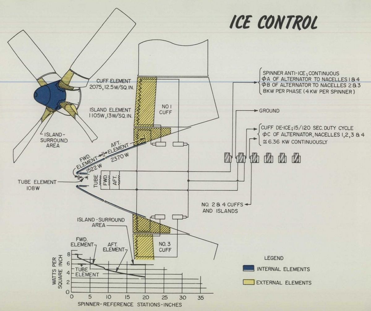
During in-flight icing conditions ice might form on some propeller components, making it necessary to either anti-ice or deice these components if icing conditions are encountered. Anti-icing is a term used to identify components that are heated continuously, while deicing is a term used to identify components that are heated in sequence by a deicer timer. "Run-back" from an anti-iced component could result in undesirable ice formations. Components immediately aft of the anti-iced areas are deiced. Thus, deicing is used to prevent accumulation of these undesirable ice formations by heating the components long enough to remove the ice, but not enough to produce "run-back". Approximately the front two thirds of the spinner is anti-iced. The deiced components consist of blade cuffs, spinner islands, and the spinner parts that are not anti-iced.
Propeller Accessories
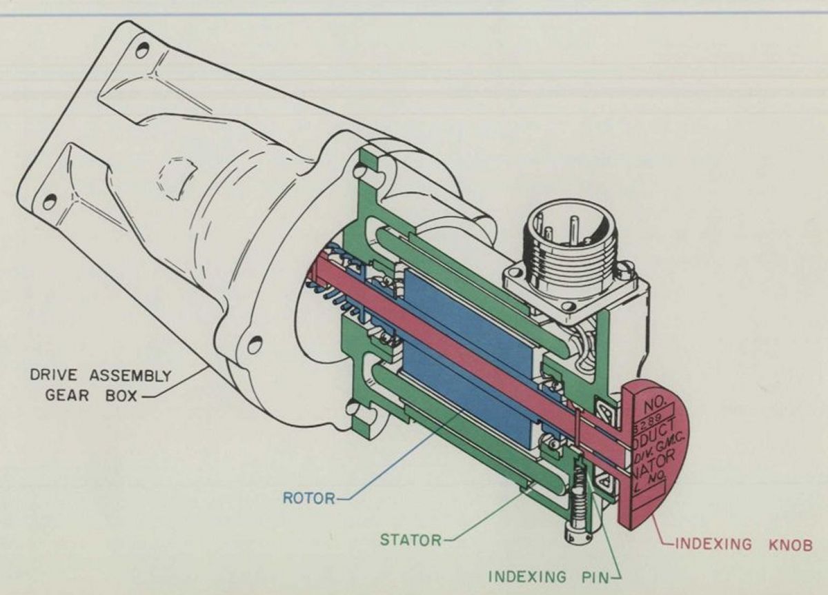 |
| Propeller Alternator |
Differences Between A6441 FN-606 and A6441 FN-606A Propellers
A 606 propeller denotes a propeller installation for a four-engine aircraft, and a 606A propeller denotes a propeller installation for a two-engine aircraft. A 606 propeller differs from a 606A propeller only in that the 606 must have more electronic controls for synchronization and phase synchronization than the 606A. A 606 installation must have three sync modules and four phase sync modules, while a 606A installation requires one sync module and two phase sync modules. For the 606 propeller installation, three sync modules are mounted in the synchronizer installation assembly, and the four phase sync modules are mounted in the phase synchronizer installation assembly. The sync module and two phase sync modules of a 606A propeller are mounted in the phase synchronizer installation assembly.
Cockpit Propeller Controls
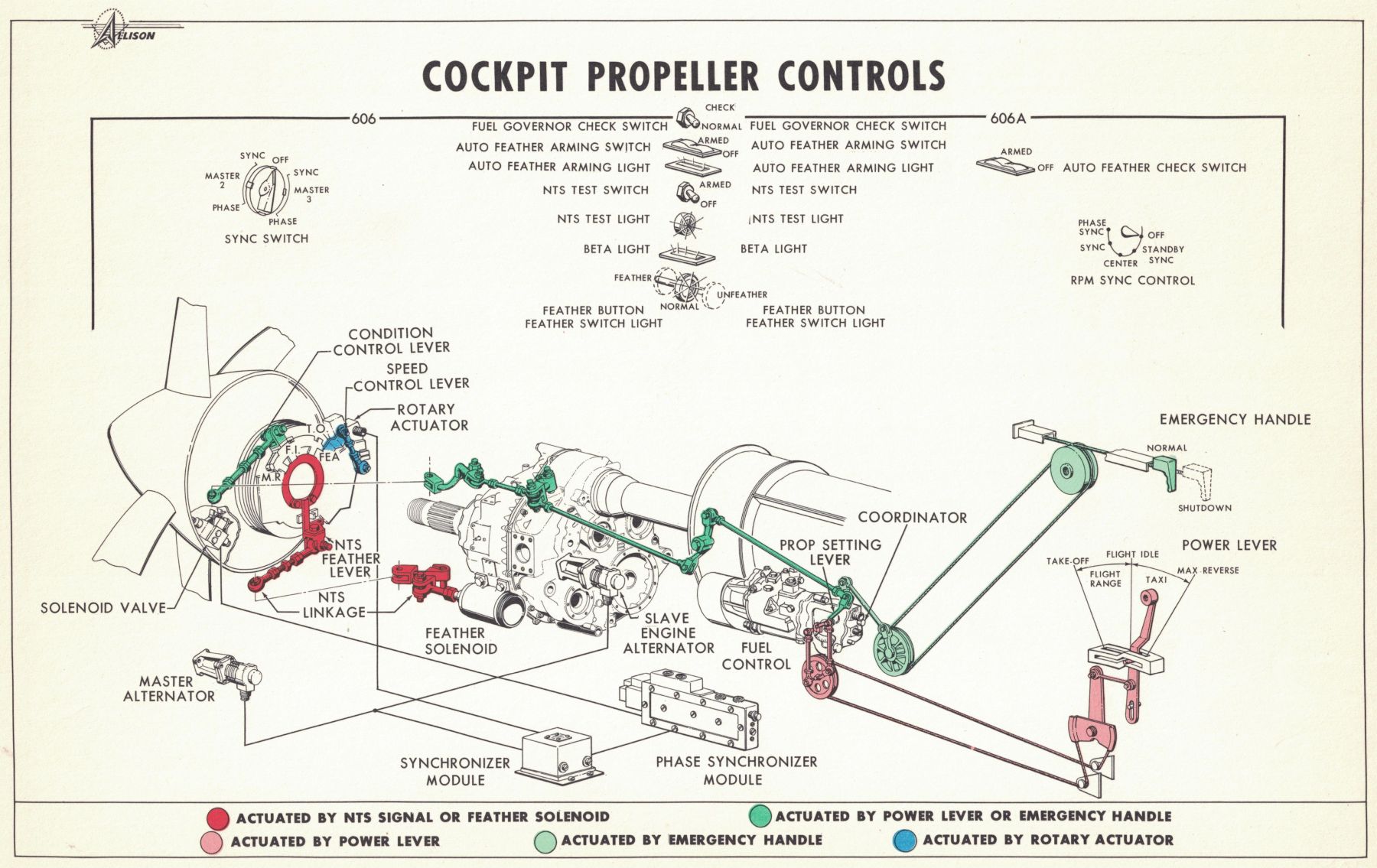 |
| Cockpit Propeller Controls |
Propeller Control Functions and Operating Range
Usually a definite value is listed for various propeller control functions. For any design, there must be maximum and minimum tolerances.
Thus, control functions will have a range of values rather than a specific value. The following table lists the ranges and the usual value listed for the control function.
| Control Function | Operating Range | Usual Value Listed |
| Minimum Torque Power Setting | 15° to 20° Co-ordinator | 17° Co-ordinator |
| Minimum Torque Blade Angle | 6.6° to 11° Blade Angle | 7° Blade Angle |
| Feather Angle | 94.7° +2°, -0.1° Blade Angle | 94.7° Blade Angle |
| Beta Follow-up Angle at Take-off Power Setting | 31.5° +0.5°, -1.0° Blade Angle | 31.5° Blade Angle |
| Mechanical Low Pitch Stop | 18.25° to 18.50° Blade Angle | 18.25° Blade Angle |
| Hydraulic Low Pitch Stop | 20° ± .1° Blade Angle | 20° Blade Angle |
| Transition, Governing Range to Beta Range | 28° to 30° Co-ordinator | 30° Co-ordinator |
| NTS Blockout Range | 21° to 24° Co-ordinator | Blocked out below 21° Co-ordinator |
| Pitch Lock Setting | 14,258 ± 13 erpm | 14,285 erpm |
| Hydraulic Governor Setting | 13,820 ± 25 erpm | 13,820 erpm |
| Low Speed Taxi | 10,000 + 300, -100 erpm | 10,000 erpm |
Conversions
A cross reference between engine rpm, propeller rpm, and percentage of rated rpm is sometimes desired. At take-off, rated engine rpm is 13,820. Since the propeller reduction gear ratio is 13.54 to 1, the propeller rpm at take-off is approximately 1,020. The take-off rated rpm is often referred to as 100% rpm. From the above information, the following equations may be derived.
% rpm = (Engine rpm / 13,820) * 100
% rpm = (Prop rpm / 1,020) * 100
Prop rpm = Engine rpm / 13.54
Abbreviations
| Β = Beta, denotes blade angle | FI = Flight Idle | MIN = Minimum |
| BFU = Beta Follow-up (Scheduled HLPS) | GI = Ground Idle | MLPS = Mechanical Low Pitch Stop |
| CF = Centrifugal Force | GOV = Governor | MR = Maximum Reverse |
| CTM = Centrifugal Twisting Moment | HLPS = Hydraulic Low Pitch Stop | NTS = Negative Torque Signal |
| DEC = Decrease | HYD = Hydraulic | PL = Pitch Lock |
| DEG = Degrees | INC = Increase | P/L = Power Lever |
| DIST = Distributor Element in Hydraulic Governor | K1 = Speed Sensitive Operation | prpm = Propeller Revolutions per minute |
| EMERG = Emergency | K2 = Acceleration Sensitive Operation | PS = Pitch Stop |
| erpm = Engine Revolutions per Minute | K3 = rpm Synchronization Operation | REV = Revolution |
| FB = Feedback | K4 = Phase Synchronization Operation | SW = Switch |
| FEA = Feather | MAX = Maximum | SYNC = Synchronize, Synchronizer, Synchronization |
Maintaining the Aeroproducts Model 606
AEHS Member Tony Vasko, who worked on Model 606 propellers in the mid-1960s, relates his experiences —
I worked on those installed on Eastern Air's Lockheed L-188 Electras. Having worked Ham Standards and Curtiss props (but not the monsters Curtiss built for the Convair B-36), I would generally rate it as a very good prop. As a mechanic circa 1964/5, I was often assigned to cut inspection view ports through the composite blade cuffs. This allowed inspection of a small blade shank area, which must have been the area where cracks developed as there was a small view.
You fit a template on the cuff forward face, gave the exact location and marked it out. Then, using a sturdy knife, you had to cut out the sheathing material. It was tough stuff. Aluminum chisels (self-made) were the used to cut down thru the dense foam filler. No steel allowed here for fear of nicking the blade shank. The square-sided hole was tapered down smaller. After cleaning up and inspecting the revealed shank section, you applied some epoxy gunk to the hole sides and smoothed it. When it was set, some transparent shellac was painted on. It was a bit nerve-wracking as any serious mistake could not be repaired.
A minor problem with the prop, as it was was oil controlled, was that it could leak slightly, very slightly, for I never saw one with droplets of oil around it. It did occasionally need oil servicing which meant it could leak. The engine air inlet was directly behind it. The Aero props were almost trouble free in my experience. Aeroproducts factory reps came by occasionally. He scorned the Ham Std’s a few airlines used as one HS had tossed a blade, which is not good. Finally, an Aero prop also did and that stopped his boasting, especially when we had to start cutting those windows in the blade cuffs.
The 501-D13 was a small engine and suffered a loss of power if the 13 compressor stage blades got dirty. Easy to check. You could easily remove the 5th and 10th stage bleed valves and look at the blades. Good engine to work.
One attached a dispenser rig between the prop and air intake, then attached supply lines. Next, the cap bleed off the engine going to the fuel control was disconnected. One needed compressed air if walnuts were used to blow them up into the dispenser. If chemical cleaning was used, one had to rig up a wash hose to flush cleaner off painted surfaces while motoring engine. One would motor the engine, then let fly with cleaner for predetermined time. Flush with water after chem cleaning, Hook up bleed lines, remove dispenser, close cowling and do power run. If water wash didn’t work, go to chem or walnuts. If still low suspect the turbine. It was easy to change whole hot section on wing
By 1964 Electras were getting old. While great machines in the pilots’ eyes, structural problems developed because of the rigid wings. Planks (wings were made of milled dural slabs) cracked, sometimes right across (easy to find as fuel came out) or the risers, which were milled, out cracked off. In one case it broke for ten feet inside the tank. These were hard to find until a major check. Eastern Air never had these problems, by the way.
When I came to the EAL Electra line in 1964, only a couple of graybeards knew of the prop workings. Systems or things like the Aero prop that give little trouble get forgotten. You get to know the troublesome ones very well. After reading this article, I now know more about the Aero prop than I did in 1965.
Send mail to
![]() with questions or comments about this web site.
with questions or comments about this web site.
![]()