Turbocompounds
by Carl Kuhns
The Wright R-3350 Turbo Compound is an air-cooled, double-row, 18-cylinder, static radial aircraft engine displacing 3,350 in³. Turbo Compounds could produce up to 3,700 take-off horsepower when using fuels available during the zenith of their service history. Cruise fuel consumption could be as low as 0.40 lb/hp/hr. Wright Aeronautical Division (WAD), a subsidiary of the Curtiss-Wright Corporation, produced many models of R-3350s between 1940 and 1960. However, the Turbo Compound was the most powerful and fuel-efficient R-3350 engine.
The goal of high horsepower and excellent fuel efficiency was achieved with the use of a process called turbocompounding, which uses the high velocity exhaust gases to drive a turbine that transfers energy to the crankshaft. Allison, Pratt & Whitney and Napier all carried out developmental work with the turbocompounding concept. However Wright was the only aircraft engine manufacturer to put a Turbo Compound engine into production.
To build an R-3350 Turbo Compound engine, Wright took an improved post-war model engine and sandwiched three power recovery turbines (PRTs) spaced at 120º intervals around the rear of the engine. The addition of the three PRTs between the power and supercharger sections added only eleven extra inches overall length compared to a non-turbocompounded engine. Each PRT is driven the by the exhaust gases of three front- and three rear-row cylinders. The power is transferred to the engine crankshaft through a fluid coupling.
Turbocompounding added about 550 horsepower at take-off power and 240 horsepower at cruise settings over a similar non-turbocompounded R-3350. These power increases were achieved with a weight penalty of about 500 pounds. Operation of the PRTs is fully automatic.
In 1942 WAD started studies on methods of power recovery. A Wright Cyclone nine-cylinder engine fitted with a single PRT was used for initial testing. A final design, sponsored by the U. S. Navy Bureau of Aeronautics, was approved in the summer of 1946. Flight test of the Turbo Compound 18-cylinder engine was made with the test engine installed in the nose of a Boeing B-17. An official 50-hour flight approval test was completed in October 1949. The 150-hour Navy Qualification test was completed in January 1950. The first production Turbo Compound R-3350s were delivered in March 1950. Initially all Turbo Compound R-3350s were for the U. S. Military. Commercial Turbo Compounds were not produced until January 1952.
Wright had plans to further develop the Turbo Compound R-3350. For high altitude operation a turbo supercharger would have been added. This turbocompounded, turbosupercharged engine would maintain sea level power to 30,000 feet. I found only one reference to this concept. A sketch was shown in the book, Aircraft Engines of the World, 1951 edition by Paul H. Wilkinson.
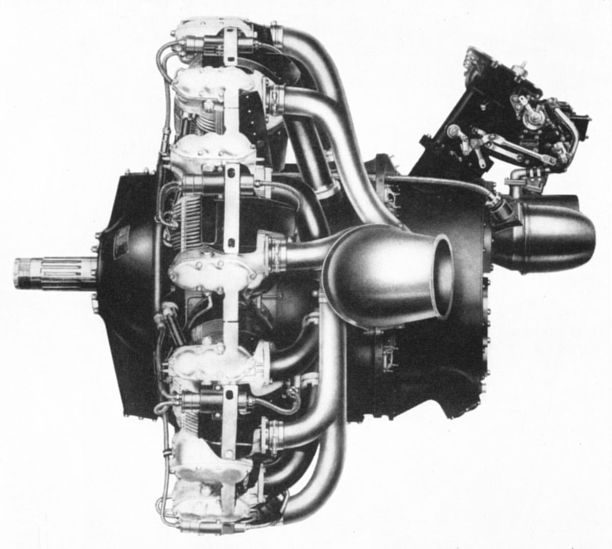
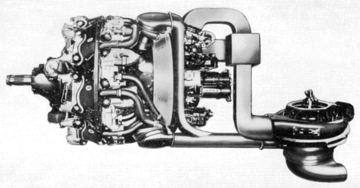
|
|
| TC9J2, a Turbocompounded R-1820 Offered in the Early 1950s | Turbocompounded and Turbosupercharded R-3350 |
WAD R-3350 Turbo Compound engines are designated first by a 3-digit specification number, followed by “TC18” and ending with a series designation. As an example, the first commercial production Turbo Compound R-3350 was designated 972TC18DA1. Military Turbo Compound engines were given two designations: a military one and WADs specification number. The first production military Turbo Compound engine can be referred to either as an “R-3350-3OW” or an “856TC18DA1.” “TC18” is also a term used when referring to Wright Turbo Compound R-3350s.
Dry weights of TC18s ranged between 3,445 and 3,775 lb depending on the model. The late model TC18EAs were the heaviest. Length of those engines is 89.5” and the diameter measures 56.6”.
The main body of a TC18 engine is composed of multiple machined sections bolted together. These sections starting from the front of the engine to its rear are: The crankcase front section, crankcase main sections, rear cam and tappet housing, supercharger front and rear housing, and supercharger rear housing cover.
 |
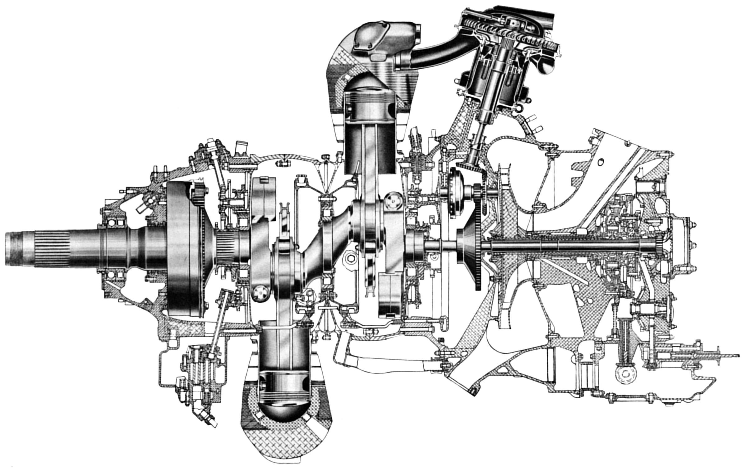 |
| TC-18 Exploded View | TC-18 Longitudinal Cross Section |
The main crankcase sections, which house the crankshaft and the cylinders, are machined from steel forgings. The remaining engine sections are machined from magnesium alloy castings.
The front crankcase section is sometimes referred to as the “nose case.” Among other components, the nose case contains the 4.5” diameter S.A.E. #60 propeller shaft. The shaft rides in two rolling element bearings. A ball bearing takes the thrust loads and a roller bearing the radial loads. The crankshaft rpm is reduced by a planetary gear reduction assembly located in the nose case. This reduction ratio is 0.4375:1; for every 16 revolutions of the crankshaft, the propeller shaft turns 7 revolutions.
One model of TC18EAs, used in the Lockheed Constellation 1649 Starliners, employed a reduction ratio of 0.355:1. Only 283 of these engines were produced.
Other components located inside the nose case are the front cam and balance weight mechanisms. The cam ring contains two tracks, one for the intake valves and one for the exhaust valves. Each track contains four lobes and rotates at 1/8 crankshaft speed. Also contained inside the nose case are nine intake and nine exhaust valve tappets. A counterbalance weight rotating at twice the crankshaft speed is also installed in the nose case. The counterbalance weight is necessary to help negate second-order vibrations. A device called a “torque meter” is enclosed inside the nose case. A torquemeter is a useful tool for in-flight engine management, giving a true indication of available horsepower at the propeller shaft.
Two low-tension ignition distributors are mounted externally on the nose case. These are located at the approximate position of 10:00 and 2:00 o’clock. At the 12:00 o’clock position is the pad to mount a propeller governor. Directly in front of the governor mounting pad is a provision to mount a hoisting eye.
The front oil sump assembly is attached at the 6:00 o’clock position on the nose case. Two pumps are located in the front sump. The smaller of the two pumps scavenges oil from lower cylinder Nos. 8-12 via a rocker box drain manifold and rocker box drain tube. The larger front sump pump collects scavenge oil from the front and front main section and along with the oil collected by the smaller oil pump sends it via an external line to the rear sump. A third pump located in the rear sump returns the oil to the oil tank.
The crankcase main section is composed of four forged and machined steel elements bolted together: the front, center front half, center rear half and rear. The center line of the cylinder rows form parting lines between front and center front, and center rear half and rear parts of the crankcase sections.
The crankshaft is constructed of three pieces. A two-throw center section accommodates the front and rear plain bearing master rods. The link rods are attached to their respective master rods by knuckle pins. The crankshaft throws are 180º apart and have a 6.312” stroke. The front and rear crank webs are clamped to the crank center section with clamp screws.
The master rods and link rods are of the H-beam type of construction rather than the more common I-beam type. Each crankshaft web has a two-piece bronze dynamic counterweight riding on floating pins. The purpose of these counterweights is to offset the rotating and reciprocating mass of connecting rod assemblies and pistons. The mounting via floating pins produces a tuned vibration absorber that reduces crankshaft torsional vibration. The crankshaft assembly rides in three roller bearings. The front crankshaft extension has external splines and a retaining nut and meshes with the propeller reduction drive gear. The rear crankshaft extension is internally splined and coupled to the crankshaft driven gear which receives power from the PRTs.
Cylinders are numbered viewing the engine from the rear. Number one is the top-most cylinder of the rear row. Number two cylinder is to the right of number one cylinder and is in the front row. The numbering continues clockwise around the engine with odd numbers being rear row cylinders and even numbers being front row cylinders. Master rods are located in cylinders one and two. The firing order of the engine is 1 - 12 - 5 - 16 - 9 - 2 - 13 - 6 - 17 - 10 - 3 - 14 - 7 - 18 - 11 - 4 - 15 - 8.
Each cylinder assembly weighs 55 lb and is attached to the crankcase with 21 cap screws. The cylinder is generic aircraft air cooled construction with a steel barrel threaded in an aluminum head. The cylinder bore is 6.125”. The barrel has replaceable aluminum cooling fins. The forged aluminum head has machined fins. Front and rear row cylinders are not interchangeable; front row cylinder push rods face forward while rear row pushrods face aft.
Two stainless steel inserts are screwed into the front and rear of the head for the spark plugs. A brass insert is screwed into the front of the head to install a fuel injection nozzle. These inserts are secured in the head with a pin driven through the insert and head. On the rear of the cylinder head, slightly below the spark plug hole is an adapter for a thermocouple.
The forged aluminum pistons have five ring grooves with one of the grooves located below the piston pin hole. The pistons are unique in that the piston pin can only be inserted from one side. Once inserted the piston pin is stopped by a shoulder machined in the piston pin bore. Only one piston pin retaining plug is then required per piston.
The rear cam and tappet housing is attached to the crankcase rear section and houses a cam ring for the rear cylinder row along with a rear second-order counterbalance.
The front supercharger housing is attached to the rear cam and tappet housing. Three mounting bosses are provided for the PRTs and nine induction tubes emanate from the front supercharger housing. Each induction tube is branched and feeds a front- and rear-row cylinder. Pressurizing these nine induction tubes is an engine driven supercharger with a 13.5” diameter impeller housed in the supercharger front housing and driven by a primary and secondary planetary gear train. This gear train gives the flight engineer a choice of two speeds to drive the supercharger impeller. Low blower speed drives the supercharger impeller at 6.45 times the crankshaft rpm; high blower speed is 8.67 times the crankshaft rpm. Generally the engine remain in low blower drive unless the aircraft is operated at altitudes above 12,000 feet. At higher altitudes high blower is selected. Mounted on the top of the supercharge rear housing is either a fuel injection metering unit or an injection carburetor The military generally preferred an injection carburetor over a direct cylinder fuel injection system. Military engines had installed either a Ceco (Chandler Evans) 58CD-11 or Bendix Stromberg PR-58TI carburetor.
An injection carburetor introduces metered fuel into the supercharger impeller where it is mixed with air and forced into the cylinders. The direct cylinder fuel injection system has more parts and is more complicated than an injection carburetor.
The direct cylinder fuel injection system employed by some TC18s consists of a master control, two injection pumps, 18 fuel injection lines and 18 individual discharge nozzles. The master control, a Bendix PR-58-52, uses the same mounting pad as an injection carburetor. The master control delivers metered fuel to the two injection pumps. The two injection pumps are mounted on each side of the supercharger rear housing. The right pump supplies the front bank cylinders. The left pump supplies the rear bank cylinders. The Bendix D9H1 injection pumps inject fuel at 500 psi during each cylinders intake stroke.
If the engine was equipped with anti-detonation injection (A.D.I.) the water pump, water regulator and injection lines were located in the area of the master control or injection carburetor. The A.D.I. fluid was injected into the engine right below the carburetor or master control.
The rear oil sump is located on the bottom of the supercharger rear housing. This rear oil sump contains two oil pumps. The rear scavenge pump collects oil from the engines rear section and from the front scavenge pump and returns this oil to an external oil tank. The pressure pump takes oil from the oil tank and sends oil throughout the engine to lubricate and cool internal engine components. A pressure relief valve regulates this oil to 70 ± 5 psi during cruise and high power settings. Both front and rear oil sumps have magnetic drain plugs and removable oil strainers. A check valve at the inlet side of the rear sump prevents the flow of oil under gravity pressure from the external oil tank when the engine is not running.
The supercharger rear cover is secured to the supercharger rear housing with a ring of studs and nuts around its outer circumference. Provisions for various accessory drives are located on the supercharger rear cover. Examples of these driven accessories are fuel pumps, hydraulic pumps, cabin superchargers, electrical generators and tachometer generators. The engine starter is located in the center of the supercharge rear cover. The Bendix Scintilla DLN-9 magneto is mounted on the top center portion of the supercharger rear cover. The magneto driven at 9/8 times crankshaft speed is one part of low-tension high-altitude ignition system. Other ignition components are an electrical conduit from the magneto to the two nose case mounted distributors.
The left distributor fires the rear spark plugs in each cylinder, whereas the right distributor fires the front spark plugs. Low voltage current is transmitted from the distributors to the cylinder head mounted step-up transformers. The step-up transformers raise the voltage to a level that will jump the spark plug gap.
 |
| Clever design of the low-tension ignition system features fully redundant electrical paths from a single 9-cylinder dual magneto. Spark advance was eventually removed from all models. |
ADs are notifications to owners and operators of certified aircraft that there is a known safety problem with a particular model of aircraft or engine. The Federal Aviation Administration (FAA) and its predecessor agencies issue ADs. The FAA was created in 1958. Compliance with ADs is mandatory. A search of the FAA web site found eight ADs pertaining to TC18s. These were issued between 1954 and 1960.
AD 54-25-02 applied to Wright models 975C18CBI, 972TC18DA1 and 972 TC18DA2. This AD required replacement of three of the intermediate cam drive gears for the front cam drive train. The replacement drive gears incorporated increased tooth width and thicker hubs. Compliance required by November 1, 1955 and at next and each subsequent overhaul. WAD service bulletins C18C-83 and TC18 -92 also addressed this issue.
AD 57-06-04 was the result of an in-flight incident of a 972TC18DA/2 powered Douglas DC-7. On March 5, 1957, American Airlines Flight 87 made an emergency landing at Memphis, Tennessee when number one engine lost its nose section and propeller. This AD mandated at the next engine overhaul the engine front section must be assembled with the propeller shaft thrust bearing (ball bearing) behind the radial bearing (roller bearing) as viewed from the propeller end of the engine. This AD applied to all C18CA, C18CB, TC18DA and TC18EA series engines. WAD service bulletins numbers C18C-252, TC18D-255 and TC-18E66 cover this same subject.
ADs 57-08-07 (which superseded AD 57-01-03) and 57-24-01 applied to all TC18DA and TC18EA series engines. These ADs addressed issue with the impeller drive gear assemblies. If the impeller drive gears fail during flight, all power is lost from that engine.
AD 58-13-05 issued June 30, 1958 addressed the problem of cylinder wall scuffing. This AD was based on earlier WAD service bulletins numbers TC18-269B and TC18 E-81B. These ADs advised operators of TC18s to replace the second chrome-plated compression ring with a cast iron ring at overhaul. A Braniff DC-7C that crashed on March 25, 1958 did not have its 988TC18EA1 engine equipped with a second position cast iron ring. Post-accident investigation of the DC-7C revealed that cylinder number 11 of the number 3 engine failed from fatigue approximately 1½ inches above its mounting flange. The failed cylinder showed evidence of scuffing and ladder cracking. Other improvements mandated by this AD concerned cylinder barrel finish, piston ring fit, use of resin graphite coated pistons and valve springs. At the next overhaul TC18EA series engine fuel injection pump timing and fuel line injection line configuration must be in accordance with applicable WAD service bulletins.
AD 59-17-01 pertained to propeller shaft cracking through the hydro-oil holes. This could cause a loss of propeller control. To prevent this type of failure, the wall of the hydro-oil holes must be inspected and shotpeened in accordance with WAD service bulletins Numbers TC-18E-178 or TC18-359.
ADs 60-03-10 and 60-08-05 dealt with the PRTs. Both of these ADs applied to all TC18DA and TC18EA series engines. AD 60-30-10 mandates the incorporation of WAD PIN 14825 valve body in the PRT oil control valve. This action will prevent inadvertent loss of oil from the PRT fluid couplings AD 60-08-05 required several maintenance checks and specific flight operation procedures. Periodic inspections for excessive clearance between various PRT components was required every 100 hours. At the same time, the turbine wheel and turbine shaft nut must be checked for security by attempting to wobble these components by hand. If looseness is detected, it is an indication the shaft or nut has been overheated. AD60-08-05 also mandated that TC18 powered aircraft should not be climbed at air speeds below the all-engine en route climb speed as shown in the FAA approved flight manual. This climb procedure provides an adequate supply of PRT cooling air.
WAD issued at least 23 service bulletins applicable to TC18s, some of which were later incorporated into ADs.
Except for a few aircraft converted for aerial firefighting, most TC18-powered airplanes have been grounded. Neptune Aviation Services of Missoula, Montana operates converted Lockheed P2V-5s and P2V-7s in the role of aerial fire fighting. Butler Aircraft Company of Redmond, Oregon has three Douglas DC-7s converted for use in aerial dropping of fire retardants.
Larry Kraus, a pilot for Butler Aircraft, responded to my request for information about his employer’s DC-7 TC-18s:
“In-house at Butler, we mainly do top overhauls, although we occasionally will change out a damaged or worn out nosecase or blower section with an overhauled unit. I’m not sure who is doing more serious overhauls when they are needed. A year or two ago, Butler found a company that now does our cylinder overhauls. I don’t know offhand who that is, but they do good work and the cylinders come with a warranty. As you can imagine, parts are scarce and therefore are increasingly more difficult to locate and are becoming progressively more expensive. The airframe parts are even more of a problem.
The engines that we use: DA4s, -42s, -93s and a couple of others, were all initially rated at 3,250 hp with 115/145. The EAs were rated at 3,450 hp. All of these engines were de-rated to 2,880 hp using 100/130 simply by reducing the allowable power settings. I’d have to look it up, but I think that the original take-off setting for the DA was 56” or 246 BMEP and 2,900 RPM. Using 100/130, we are allowed 53” or 234 BMEP and 2900 rpm (standard day at sea level). With only 100LL available, we use 50” and 2,900 rpm not to exceed 234 BMEP. We are also restricted to low blower and the spark advance has been disabled.
We have three DC-7s. Tanker 60 is an ex-Eastern DC-7B (N838D). Tanker 62 and Tanker 66 are both ex-United DC-7s. Tanker 66 is N8353C. Tanker 62 is now N401US from its last owner, US Overseas Airways. The United registration for T62 was N6331C.
The interval between top overhauls varies, but is generally between 700-1,000 hours. The US Forest Service used to set 1,700 hours as a TBO on R-3350s, but would allow extensions if an engine met certain specs and was in an oil analysis program. We routinely get 2,000 hrs before TBO. I’ve had several engines last 2,200 hrs and one that lasted 2,400.”
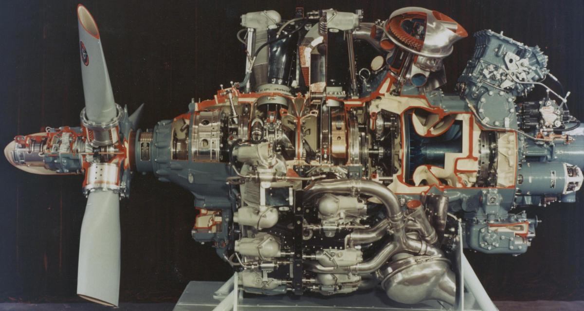 |
| Factory TC-18 Cutaway |
| Commercial TC18 Engine Installations | |||
|---|---|---|---|
| WAD Model | Takeoff BHP |
Airplane Installations |
Remarks |
| 972TC18DA1 972TC18DA2 |
3,250 | DA1 Lockheed 1049 B, C, E DA2 Douglas DC-7 |
First commercial turbocompound, DA1 and DA2 differ by installation provisions |
| 972TC18DA3 | 3,250 | Lockheed1049E 1049B |
Identical to 972TC18DA1 except for incorporation of increased capacity main bearings, improved pistons, and improved PRT cooling air impellers |
| 972TC18DA4 | 3,250 | Douglas DC-7B | Identical to 972TC18DA2 except for incorporation of increased capacity main bearings. Improved pistons, and improved PRT cooling air impellers. |
| 988TC18EA1 988TC18EA3 |
3,400 | EA1 DouglasDC-7C EA3 Lockheed1049G 1049H |
Features of 988TC18 EA1, EA3 include 4,000 HP reduction gear, strengthened crankcase, improved cylinders and pistons, improved PRT and rear section components for added durability. |
| 988TC18EA2 | 3,400 | Lockheed 1649 | 988TC18EA2 is similar to 988TC18EA1 and 988TC18EA3, except reduction gear ratio. 988TC18EA2 has steel cam and tappet housing, which is an integral part of the crankcase. |
| 988TC18EA4 | 3,400 | Douglas DC-7C | 988TC18EA4 is similar to 988TC18EA1, except for improvements which permit increased cruise power. |
| 988TC18EA5 | 3,400 | Lockheed 1649 | 988TC18EA5 is similar to 988TC18EA2, except for improvements which permit increased cruise power. |
| 988TC18EA6 | 3,400 | Lockheed 1049 G, H | 988TC18EA6 is similar to 988TC18EA3, except for improvements which permit increased cruise power |
| 981TC18EA1 | 3,700 | Canadair CL-28 (RCAF CP-107) |
981TC18EA1 differs from 988TC18EA1 and 988TC18EA3, in that it has water injection provisions. |
| Source: Operations Engineers Handbook Section 3 | |||
| Military TC18 Engine Installations | ||||
|---|---|---|---|---|
| Military Designation | WAD Model | Take-off B.H.P. | Airplane Installations |
Remarks |
| R-3350- 30W | 856TC18DA1 | 3,250 | LockheedP2V-4, -5, -6 | Impeller injection. Manifold pressure regulator. |
| R-3350-30WA R-3350-36W |
856TC18DB1 856TC18DB2 | 3,500* 3,250 |
Lockheed P2V-4, -5, -6, -6B | Impeller injection. No manifold pressure regulator. Water injection, R-3350-36W has drilled turbine wheel. |
| R-3350-32W | 878TC18EA1 | 3,700* | Martin M270, P5M-2 Lockheed P2V-7 |
Impeller injection, water injection. |
| R-3350-34 | 872TC18DA1 | 3,250 | Lockheed RC-121D, R7V-1, WV-2, WV-3, C-121F, WV-1, C-121C, RC-121C | Direct fuel injection. Internal torquemeter line. Commercial equivalent is 972 TC18DA1. |
| R-3350-38 | 932TC18EA2 | 3,400 | Lockheed C-121, W2V-1 | Commercial equivalent is 988TC18EA2. Direct fuel injection. |
| R-3350-85 R-3350-89 |
868TC18DB1 868TC18DB2 |
3,500* | Fairchild C-119E, F, G Fairchild R4Q2 |
Impeller injection, water injection. R-3350-89 has drilled turbine wheel. |
| R-3350-91 | 923TC18DA1 | 3,250 | Lockheed C-121C, RC-121C, RC-121D | R-3350-91 is a -34 with manual spark advance. |
| * = Wet Rating Source: Operations Engineers Handbook Section 3 | ||||
| Commercial TC18 Engine Production | ||
|---|---|---|
| WAD Model | Number built | Production period |
| 972TC18DA1 | 596 | 1/52 – 2/55 |
| 972TC18DA2 | 374 | 8/52 – 12/54 |
| 972TC18DA3 | 614 | 10/54 – 8/58 |
| 972TC18DA4 | 642 | 11/54 – 1/58 |
| 988TC18EA1 | 903 | 10/55 – 9/58 |
| 988TC18EA2 | 283 | 6/54 - 11/58 |
| 988TC18EA3 | 294 | 1/56 – 7/58 |
| 988TC18EA4 | 159 | 9/57 – 7/58 |
| 988TC18EA6 | 80 | 12/57 – 12/58 |
| 981TC18EA1 | 203 | 1/56 – 4/59 |
| Total = 4,148 | ||
| Source:Historical Engine Summary | ||
| Military TC18 Engine Production | |||
|---|---|---|---|
| WAD Model | Military Model | Number built | Production period |
| 856TC18DA1 | R-3350-30W | 559 | 3/50 – 12/51 |
| 856TC18DB1 | R-3350-30WA R-3350-30WB |
1,348 61 |
11/51 – 3/54 9/52 – 4/53 |
| 878TC18EA1 | R-3350-32W | 1,316 | 8/53 – 1961 |
| 872TC18DA1 | R-3350-34 | 1,640 | 6/52 – 9/57 |
| 868TC18DB1 | R-3350-85 | 2,395* | 9/51 – 1954 |
| 868TC18DB2 | R-3350-89 | 24 | 1/55 – 3/55 |
| 923TC18DA1 | R-3350-91 | 4,653 | 5/55 – 8/56 |
| Total = 11,996 | |||
| * includes licensee production Source:Historical Engine Summary | |||
TC18s were manufactured in two locations: Tonawanda, New York and Wood-Ridge, New Jersey.
During World War II, Chevrolet Motor Division in Tonawanda, New York produced Pratt & Whitney R-1830 and R-2800 engines under license at the Aviation Engine Plant. In 1952, that Chevrolet engine plant started producing the non-Turbo Compound 2,700 hp R-3350-26W. In early 1953, the TC18 R-3350-85 was added to the list of engines made at the Tonawanda plant.
The majority of Turbo Compounds were manufactured by Wright Aeronautical Corporation in Wood-Ridge New Jersey. This facility was built in 1942 to produce R-3350 engines for the B-29 and B-32 bomber programs.
The Wood-Ridge facility was a huge complex with two dozen buildings on 138 acres of land. After Wright ceased making aircraft engines, other Wright products were made there. In 1983 the plant was closed and Curtiss-Wright sold the Wood-Ridge Facility for $51M in 2001.
1. Aircraft Engines of the World 1951 Edition by Paul H. Wilkinson
2. Janes All the Worlds Aircraft 1958-1959
3. Wright Aircraft Engines Series TC18DA Service Manual Curtiss-Wright Corporation Wright Aeronautical Division June 1953
4. Wright Aircraft Engines model 988TC18EA Parts Catalog Curtiss-Wright Corporation Wright Aeronautical Division, December 1955
5. Facts about the Wright Turbo Compound, Published by Field Engineering Department,
Curtiss-Wright Corporation Wright Aeronautical Division October 1956.
6. Federal Aviation Administration Type Certificate Data Sheets E-272 and E-287 December 28, 1983
7. “Turbocompounding the Wright Way”, by Tom Fey, Journal of the Aircraft Engine Historical Society Volume 5, Number 2
8. “Torquemeters, Developments through 1945” by Kimble D. McCutcheon Journal of the Aircraft Engine Historical Society Volume 4, Number 2.
9. Historical Aircraft Accident Reports (1934-1965) Online Digital Special Collections Library www.dotlibrary.specialcollections.net
10. Neptune Aviation Services www.neptuneaviation.com
11. Butler Aircraft Company www.butleraircraft.com
12. Operations Engineers Handbook, Curtiss Wright Corporation, Wright Aeronautical Division, January 23, 1957
13. Historical Engine Summary (Beginning 1930), Wright Aeronautical Division, Curtiss-Wright Corporation, www.enginehistory.org/reference.htm
14. Telephone and e-mail exchanges with Kimble D. McCutcheon
15. E-mail exchanges with Larry Kraus, pilot, Butler Aircraft.
16. Airworthiness Directives—ADs by make and model,
www.faa.gov/regulations_policies/airworthiness_directives
17. "Curtiss-Wright Aircraft Engine Factory". The Unquiet Tomb.
Send mail to
![]() with questions or comments about this web site.
with questions or comments about this web site.
![]()