Rolls-Royce Merlin Automatic Boost Regulator
Courtesy of Dave Birch and the Rolls-Royce Heritage Trust
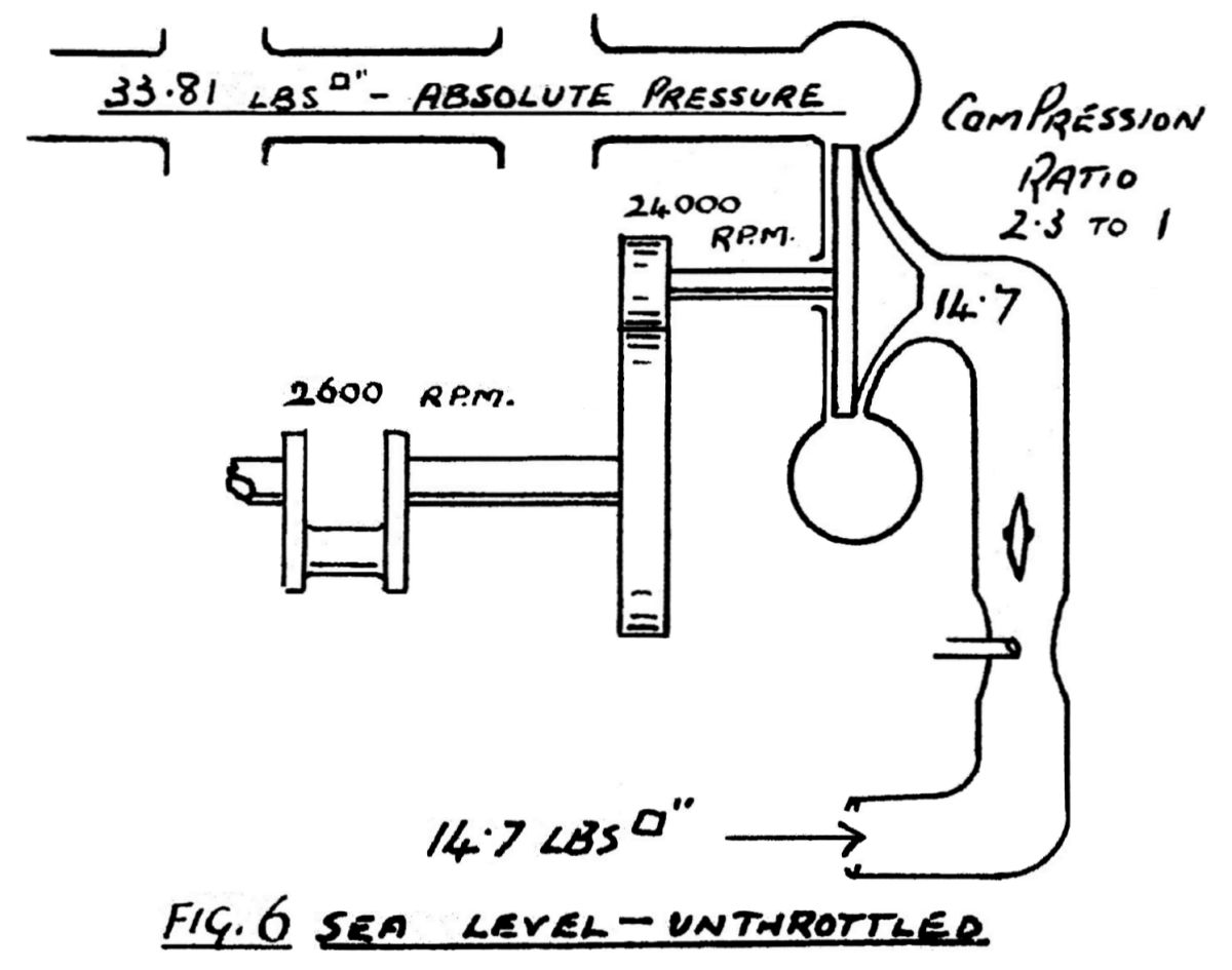
A supercharger capable of producing Rated Boost at an altitude greater than sea level would create an excessive boost pressure at lower altitudes if uncontrolled. To illustrate this point the blower may be represented as a simple compression device, an engine similar to Merlin III being taken as a typical example. The figures approximate to those on illustration (Fig. 6). Compression Ratio of blower 2.3:1 with an impeller speed of 24,000 R.P.M.
At sea level an absolute pressure in induction manifold of 33.81 psi would be obtained. From this figure we must deduct 14.7 psi (which equals 0 psi boost) to obtain the positive boost pressure
| 33.81 | (absolute induction pressure) | |
| 14.70 | 0 psi boost | |
| ===== | ||
| +19.11 | positive boost |
so that at normal crankshaft R.P.M. this engine would produce at sea level almost 20 psi positive boost on a day of standard barometer.
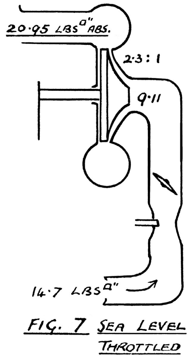
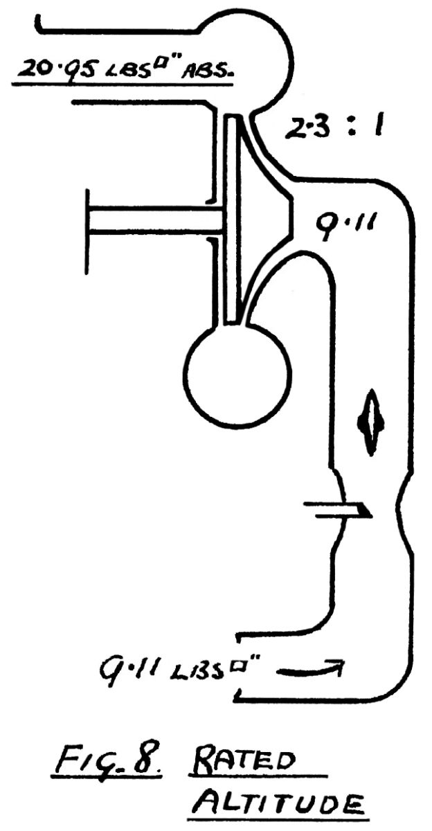
This is considerably in excess of the maximum boost limitation, and is suitably reduced by throttling (Fig. 7). The amount of throttling required will depend upon atmospheric pressure available at intake and will decrease until an altitude is reached at which, with crankshaft turning at International R.P.M., Rated Boost can be obtained only with throttles wide open. This is Rated Altitude (Fig. 8).
|
|
|
The control of carburettor throttles to obtain and maintain the required boost pressure up to the full throttle height is the function of the boost regulator. Figure 9 shows the potential boost pressures of the specimen engine at 2600 R.P.M., the shaded area representing the excessive values of boost which are circumvented by the action of the boost regulator reducing the throttle opening.
Also illustrated is the comparative altitude at which the boost pressure will commence to drop on reaching the full throttle line at fixed engine R.P.M. The +12 psi (emergency boost) and the +2.25 psi (economical cruising boost) are marked in as examples. It should be noted, however, that owing to mechanical limitations of the control assembly, any boost pressure less than Rated Boost could not be controlled to the full throttle height by the action of-the regulator alone.
To obtain full throttle at any time. requires the fulfilment of both the following conditions:
(1) That relay piston in regulator is against "stop" at forward end of stroke.
(2) That pilot's lever must be at the full forward end of quadrant (on a gated engine, "at the gate").
 |
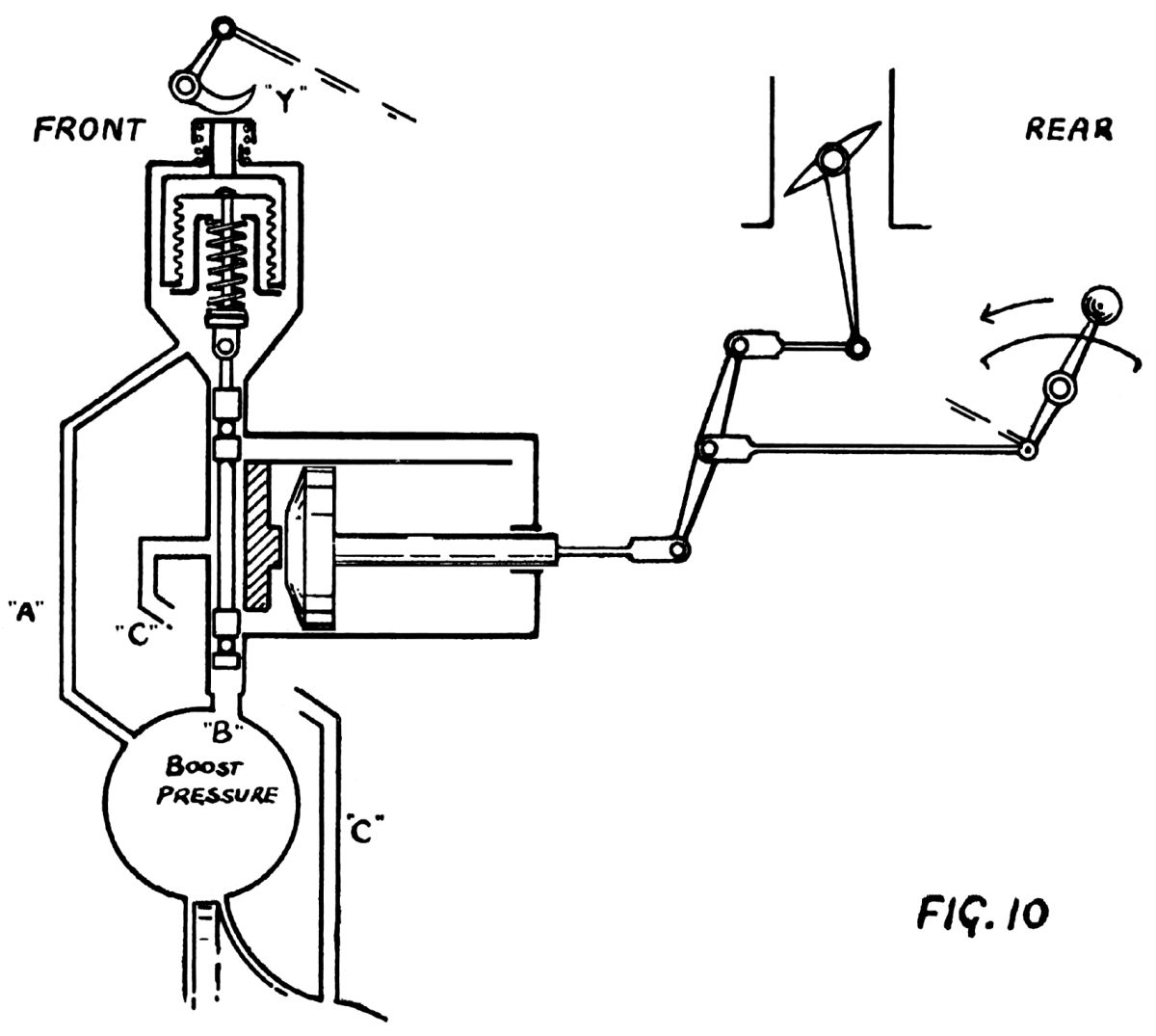 |
The action of the regulator is laid out in Figure 10, where the pilot's lever is connected to a swinging link which represents the gear differential actually used in simple form. It should be noted that with relay piston in position shown — forward end of stroke — pilot's lever has full range and control over the butterfly throttles. This control remains positive until boost pressures in the order of 0 psi are obtained. From then onwards the boost regulator will take charge of the throttles according to the relative position of controlling aneroid as determined by pilot's lever operating cam "Y". The action of the regulator is briefly as follows:
Pressure from supercharger volute is applied through passage "A" to a chamber housing a sensitive aneroid. Attached to aneroid is a simple piston valve. This valve has two controlling "lands"; these are so spaced-and of such dimensions as to be capable of simultaneously closing the two transverse passages which are in communication with either end of the relay piston. The relay piston has a length of travel which is capable of being applied to the throttles through the swinging link without any movement of the pilot's lever. The leverages are so arranged, however, that the full movement of relay piston travel does not equal the complete range of throttle movement.
The piston valve acts as a distributor for boost pressure fed through passage "B" from supercharger volute. This pressure can pass through hollow centre of valve to the upper set of holes in piston neck or to lower set. The two smaller "lands" at extreme ends of valve supply additional bearing surfaces, the uppermost also acting as a seal to prevent direct communication between passage "B" and aneroid chamber. Passage "C" connects the supercharger entry (negative pressure)) to the annular space around piston valve stem between controlling lands.
It will be seen that, except when ports connected to relay piston are closed by piston valve, boost pressure will be fed to one side of relay piston whilst negative pressure is connected to the other, the direction of flow depending upon whether piston valve is raised or lowered. This difference of pressure acting upon the large area of relay piston head will cause movement to occur which will directly operate the butterfly throttles in a direction that will cause the piston valve ultimately to be maintained in such a position as to close both ports, the throttles then being held and the boost pressure controlled within the limit of the regulator's range of action.
At slow running the depression existing throughout the whole induction system would permit the aneroid balance spring to lower piston valve. Depression would then be connected to front of relay piston, atmospheric pressure being applied to rear end through an atmospheric changeover cock in passage "B". This is omitted from sketch (Fig. 10) and piston valve is shown in the controlling position, otherwise the illustration shows the conditions existing at slow running.
If, with the engine running against the chocks, we now move the pilot's lever forward the full extent of its travel, throttles will be opened wide and cam "Y" will depress aneroid and piston valve bodily to the Rated Boost position. R.P.M. and boost pressure will rise rapidly and exceed Rated Boost. At this point, however, the excess pressure acting on the aneroid will raise piston valve until controlling lands are above their respective ports. Boost will be admitted now to front end of relay piston and depression to the rear causing relay to move rearward, thus closing the throttles. This will continue until the boost is reduced below the rated value, allowing piston valve to drop, causing a reversal of pressure on relay piston which will move and slightly open throttles to compensate. These reversals and changes occur in rapidly diminishing magnitude until finally the throttles are stabilised in the Rated Boost position. It should be noted that the final position of relay piston is almost at the full rearward end of its travel. Further slight rearward movement is available to prevent a rise in boost on a day of higher barometric pressure and to curtail any tendency for boost to rise with forward speed of aircraft.
If the aircraft is now climbed steadily without alteration in pilot's lever position, the fall of boost in sympathy with decreasing atmospheric pressure is prevented, the sensitive aneroid so controlling piston valve that relay is gradually moved forward, boost pressure remaining. constant, until at rated altitude throttles are wide open.
To appreciate the limitations of control of lesser boost pressures, consider the example of take-off and climb at +4 lb/sq.in boost. With engine at slow running, pilot's lever is moved to position on quadrant giving +4 psi boost, this being only part of the possible range on quadrant, throttles will only partially open and cam "Y" will only partly depress the sensitive aneroid. Regulator will again control, but owing . to throttles partial opening by pilot's lever, relay movement available to correct is reduced. On climb, boost pressure will be maintained by return of relay piston to forward position which continues until piston contacts forward stop. Boost pressure would then fall with increase of altitude, although throttles are not wide open; to continue the climb at +4 lb boost is only possible by manual operation of the pilot's lever. When this is at full forward position on quadrant, throttles are wide open and at higher altitudes the boost pressure will necessarily fall.
The action of operating emergency cut-out valve introduces a calibrated depression leak into passage "A", between supercharger volute and aneroid chamber. The aneroid must control the pressure it receives to its original value of Rated Boost — providing pilot's lever is in Rated Boost position, but to do this the actual pressure in volute must be at a higher value, the calibration on Merlin engines giving +12 psi
Gate Control
On gated engine a high take-off boost is obtained by going through the gate, the pressure obtained may be of the same nominal value as emergency boost, +12 lb, but the method of control is entirely different. With pilot's lever at gate, relay piston has moved almost fully rearward to control at Rated Boost - +9 lb. The action of going through the gate opens the throttles a positive predetermined amount, causing boost to rise. Regulator piston will then complete its rearward travel in an endeavour to hold boost down to 9 lb, but has insufficient range to do so and has no effect.
As through the gate is a fixed throttle position, boost obtained will vary in ratio to the day's atmospheric pressure, and will fall with altitude, the regulator having no control at all under these conditions, although it would maintain the boost when value has fallen to +9 lb. This condition should never arise, as "through the gate" should only be used to 1000 ft.
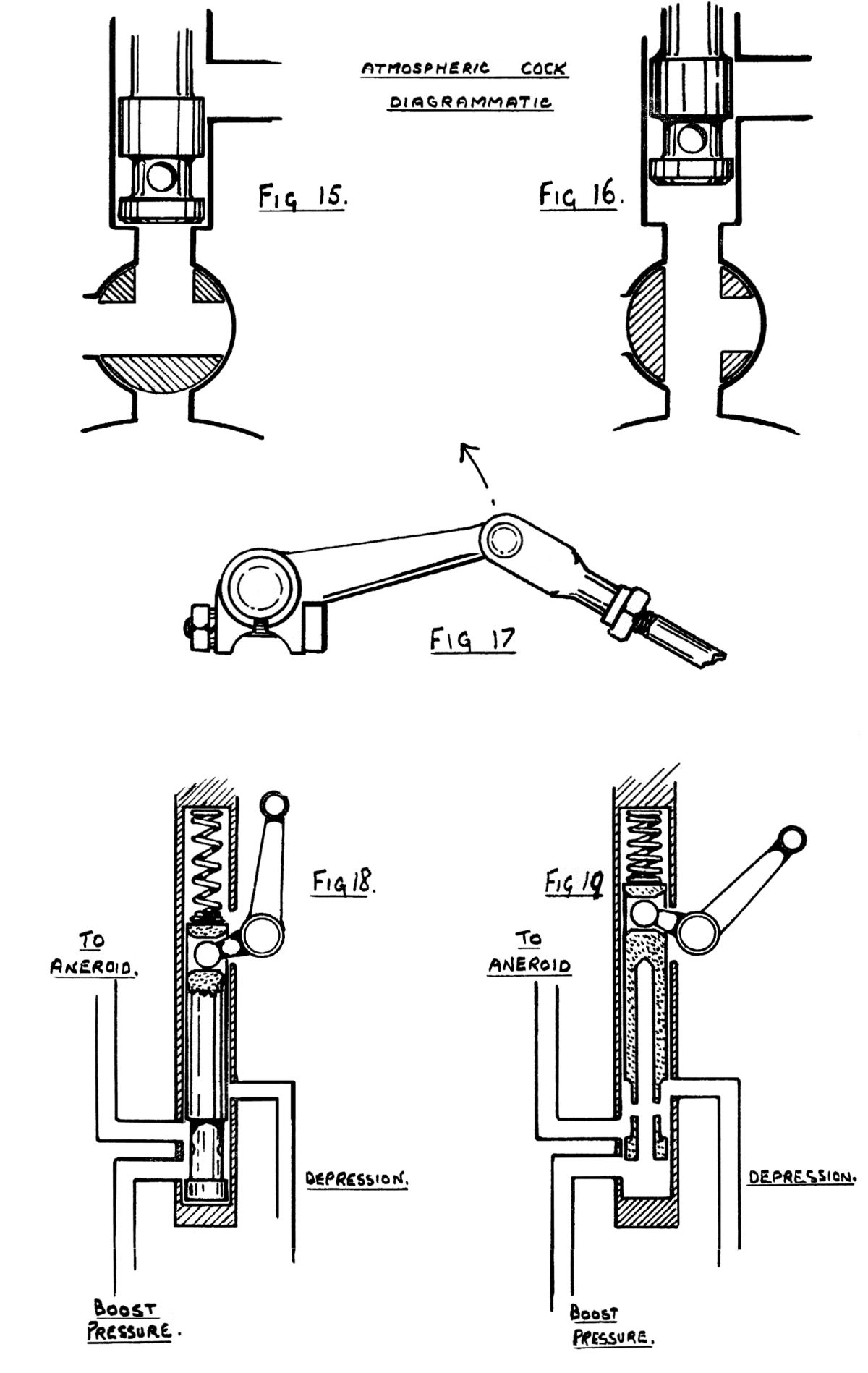
Atmospheric Changeover Cock
The atmospheric changeover cock (Fig. 15) is fitted to provide the necessary pressure difference to energise relay piston when pressure values at input and output of supercharger impeller are equal, i.e. as at slow running, where, owing to low rotor speed, the pressure build-up across blower is nil. Under these conditions the changeover cock directly operated by pilot's lever closes passage "B" from supercharger volute and opens port to atmosphere. This condition persists when opening pilot's lever until approximately 0 lb boost is attained, at which point atmospheric ports are closed, and pressure from volute is reinstated.
In the interests of more stable action of boost regulator, Modification No. 199 includes the fitting of a bias spring to rear of relay piston. It will be seen that this spring applies its pressure in the same direction that atmospheric pressure is applied by distributor piston valve during slow running. The deletion of the atmospheric changeover cock therefore becomes a possibility, but owing to the light spring loading, the retention of atmospheric pressure is desirable to ensure positive action.
 |
Emergency Cut-Out
The emergency cut-out is a simple piston type valve which permits a higher value of boast to be obtained within the limit of supercharger output. It functions as shown in Figure 18, where passage "A" from volute to aneroid chamber is via the neck of pistonvalve which is normally-held in lower position by the action of spring “Z”. The upper passage "C" is in communication with supercharger inlet but remains blanked off from aneroid chamber by full diameter of piston valve stem until cut-out is operated from cockpit (Fig. 19). In the operated condition depression passage is connected to aneroid chamber boost feed and a fictitious sample is applied to aneroid which will control it up to the original value. If pilot's lever is set for Rated Boost, the sample will be brought to Rated Boost and, with correct ratio of Boost/depression feed to aneroid chamber, the pressure in volute can be stabilised at any pre-determined value, the calibration being effected by diameter of transverse hole “X”.
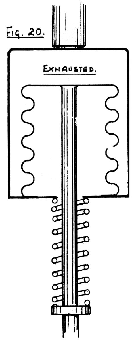
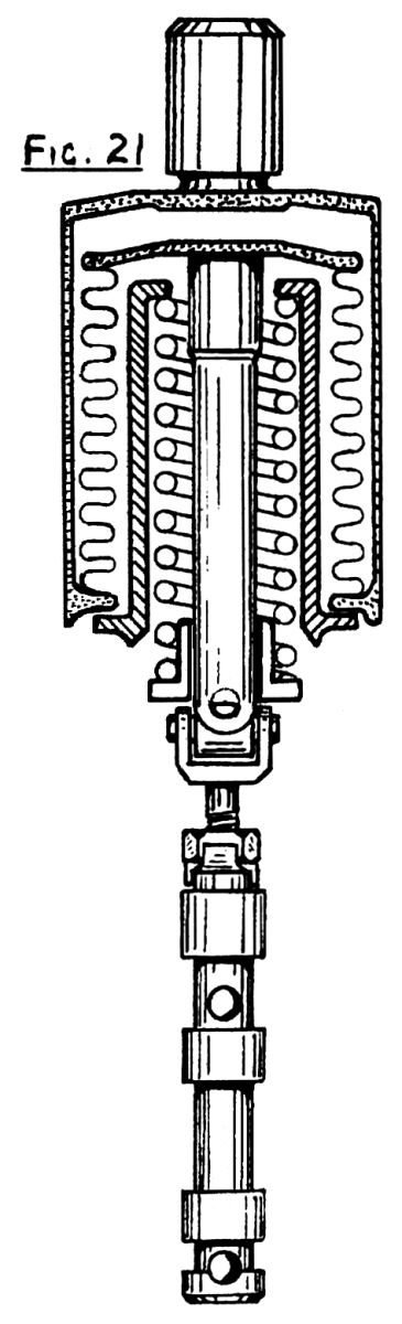
Sensitive Aneroid
The controlling aneroid consists of an outer rigid cylindrical shell sealed to which is a flexible metallic bellows (Fig. 20), the space between the two being exhausted as completely as production contingencies will permit. This is necessary to get the minimum thermal expansion effect and at the same time permit a reasonable range of sensitivity. A balance is maintained by the pressure of a coil spring which is interposed between outer casing and stem which is attached to bellows, a diagrammatic sketch being shown in Figure 20, and the more complete practical version in Figure 21. The latter is made more compact by the housing of pressure balance spring inside a flanged aluminium sleeve which also provides an abutment to limit — the travel of bellows when subject to a decrease of pressure. The piston valve is attached through a universal joint to the central stem, the aneroid being so calibrated that under normal sea level atmospheric conditions a change of pressure in either direction will cause a movement of piston valve, the greatest travel being available on the pressure increase side.
 |
 |
Faulty Operation
There are several possible sources of boost pressure fluctuations and/or erratic functioning of regulator, the most common being tabulated below:
| Symptom | Cause |
|---|---|
| 1. Uncontrolled boost pressure | Failure of aneroid |
| 2. Low boost pressure (gauge reading) | Leak in line to boost gauge, leak at bezel of gauge, or leak at fuel trap. Slipping clutches. |
| 3. Surging | Sticking piston valve or relay piston. Slack in controls to pilot's lever in cockpit. |
| 4. Erratic boost pressure control | Sticking piston valve or relay piston. Leak at velumoid joint between regulator and supercharger casing. Leak at cap nut covering feed passage to aneroid chamber, changeover cock lever replaced in incorrect position, with pinch bolt above instead of below spindle. (Correct condition should be as in Figure 17). |
Any of the above symptoms may be due to a combination of causes.
Send mail to
![]() with questions or comments about this web site.
with questions or comments about this web site.
![]()