Pratt & Whitney Wasp (R-1340)
Compiled by Kimble D. McCutcheon
Published 15 Apr 2020

Pratt & Whitney Wasp (Mike Smith) |
The Pratt & Whitney Wasp (R-1340) was P&W's first engine. Its initial takeoff rating was 430 hp, but later some models had takeoff ratings of up to 650 hp.
Wasps powered numerous single- and multi-engine aircraft, including executive transports, sport planes, racers, fighters, passenger transports, WWII training aircraft, agricultural aircraft and helicopters.
P&W and its licensees produced a total of 34,966 Wasps between 1926 and 1960. It had the longest production run of any P&W engine. |
Wasp Description
Type = 9-Cylinder Air-Cooled Radial
Bore = 5.750" Stroke = 5.750" Displacement = 1,343.8 in³
Cylinders are built up of cast aluminum heads with integral valve mechanism housings, screwed and shrunk onto forged chrome-molybdenum steel barrels having integral fins. Individually removable baffles provide uniform cooling air distribution under severe flight conditions
Pistons having flat heads with valve clearance recesses are machined from aluminum alloy forgings. The piston crown underside is ribbed for strength and increased cooling area. Three compression rings, two dual oil control rings and one oil scraper ring comprise the ring pack. The compression ratio is 6:1.
The master rod has eight "I" section articulated rods attached by knuckle pins. These articulated rods are fitted with bronze bushings in both knuckle pin and piston pin ends. The master rod has a plain lead-bronze crankpin bearing.
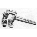
The crankshaft is a single-throw, two-piece type machined from forged alloy steel. It is supported by a roller bearing on each side of power section and a ball thrust bearing in the nose section.
The crankcase nose section is a hemispherical aluminum forging, which, on geared engines, houses planetary reduction gears. There is a pad for mounting the propeller governor. The propeller thrust bearing is mounted at the front end of the nose section.
The main crankcase section consists of two similar forged aluminum alloy sections, machined together, divided on the cylinder center line and united by through bolts and cylinder flanges. The front main crankcase also supports the cam and cam reduction gear. Valve tappets mounted in guides are located in a front main crankcase extension directly over the cam track.
The crankcase blower section contains the centrifugal supercharger and features mounting lugs for installing the engine.
The crankcase accessory section carries all accessories and has integrally cast vanes in the carburetor intake elbow for balanced fuel mixture distribution.
The valve gear is completely enclosed. A cam drum rotating opposite the crankshaft direction at one-eighth crankshaft speed drives overhead valves through tappets, push rods and rocker arms.
The Induction System consists of a Stromberg self-priming carburetor with idle cutoff, primer tubing and mixture distributor. Mixture is fed from carburetor through intake elbow to the supercharger and diffuser, where it is compressed. Tangential intake pipes exit the supercharger diffuser and feed the cylinders.
The supercharger impeller runs on an impeller shaft coaxial with the crankshaft and driven from it through a spring coupling mounted inside the crankshaft gear.
The ignition system consists of two Scintilla magnetos located on the accessory section, each independently firing spark plugs in all nine cylinders. Front and rear Pratt & Whitney type radio-shielded ignition manifolds provide short leads to the spark plugs.
Forced lubrication is provided for direct drive engines by a gear type pump in the rear section. Oil under pressure is passed through blower section, then through internal piping in the lower part if the power section above the sump into a separate line in the nose section to the propeller control valve. Pressure oil from the nose is led through distributing grooves around the tappets, to metering ports that automatically lubricate the tappets, push rods and valve gear under constant pressure, The waster rod bearing, knuckle pin bushings, cam and cam gear are all force-lubricated from pressure oil, Accessory shafts and supercharger gearing is lubricated by drilled passages from the rear section oil strainer chamber and an oil jet in the main oil feed line, All other parts are lubricated by mist or spray from pressure-oiled parts, Geared engines are similar except that there is an oil feed pipe in the reduction gear housing that carries oil to the ball thrust bearing and reduction gears.
The reduction gearing consists of a driving sun gear splined to the crankshaft and supported by a roller bearing in the anchor plate. A fixed ring gear is bolted to the nose section, and meshes with six planet gear pinions in a gear cage that is splined to the propeller shaft. The gear ratio is 3:2.
Accessory drives are grouped in the rear section and driven by three layshafts extending entirely through the blower and rear sections. Each layshaft carries a spur driven gear at its forward end, which engages the drive gear attached to the crankshaft rear of , The upper shaft provides drives for starter and generator, Each of two lower shafts drives one magneto through an adjustable coupling. By a bevel gear on each lower shaft, four vertical drives are provided. The upper ends of these are drives for various types of accessory pumps or gun synchronizers. Two tachometer drives projecting outward from the rear case are driven through worm gears at right angles to the vertical shafts. The lower shafts, driven from the same bevel gear, drive the oil pump on the right and the fuel pump in the left On the engine's left side a third bevel gear suitable for driving a vacuum or hydraulic pump meshes with a bevel gear on the magneto driveshaft.
Wasp Parts
 |
 |
 |
 |
 |
 |
 |
| Cylinder Numbering |
Cylinder |
Piston |
Rods |
Crankshaft |
Crankcase Nose Section |
Crankcase Main Section |
 |
 |
 |
 |
 |
 |
 |
| Main Section Front |
Blower Section |
Accessory Section |
Accessory Drives |
Cutaway |
Supercharger Gears |
Valve Timing |


