Junkers Jumo 222
 |
The two Air Intelligence reports are from The National Archives of the United Kingdom at Kew, courtesy of Dave Birch.
Editorial Comment: These reports should be viewed as snapshots of evolving German aircraft engine development programs from the end of WWII. As such, they contain factual errors and even contradict one another. Still, they are valuable for their description of the technology and provide useful insight into German design and construction. A more detailed account of this engine was published in Torque Meter Vol. 6, No. 3 (Summer, 2007).
|
A.I.2.(g) Report No. 2309
Junkers Jumo 24-Cylinder Aero-Engine
The Jumo 222, an engine of original and strikingly compact design, was first reported on by Intelligence sources as far back as 1941. It has since been mentioned at frequent intervals.
Information recently obtained from captured German documents and P/W [prisoner of war] sources indicates that this engine, after prolonged and serious development troubles, is now in production, and may shortly appear in service. Sub-types A-l, A-2, B-1 and B-2 have already been identified.
General Description
24-cylinder, liquid-cooled "parallel radial", consisting of six blocks of four cylinders arranged equidistantly around the crankcase. Two inlet and one exhaust valve per cylinder operated by single overhand camshafts through the normal Junkers-type rocker gear. Single-stage, two-speed centrifugal supercharger. Two magnetos. Pressure cooling (max. coolant temp. 120°C). Fuel B4 (87 octane) or C3 (100 octane) in emergency.
| Diameter of engine: |
1,150 mm |
(45.0”) |
| Length of engine: |
2,200 mm |
(86.5”) |
| Bore: |
135 mm |
(5.3”) |
| Stroke: |
135 mm |
(5.3”) |
| Swept volume: |
46.6 liters |
(2,844 in³) |
| Compression ratio: |
6.5:1 |
|
| Reduction gear ratio: |
2.714:1 |
|
| Diameter of inlet valves: |
55.3 mm |
(2.177”) |
| Diameter of exhaust valves: |
63.5 mm |
(2.500”) |
| (sodium cooled) |
|
|
| Valve seat angle: |
45° |
|
The valve seats are treated with a deposit of 75% nickel, 20% chromium and 1.8% boron (similar to British “Brightray”).
Reported weight as complete power-egg: 1,830 kg (4,030 lb)
Take-off power (unspecified sub-type): 2,500 hp at 3,100 rpm at 1.62 ata boost (8.3 lb)
It is believed that a version exists wit the compression ratio raised to 7.3:1, fitted with a turbo-supercharger and operating normally on C3 (100 octane) fuel.
Application to Aircraft
The Jumo 222 was to have been installed in one version of the Ju 288, and Fw 191 bombers and in a version of the He 177. A P/W has recently stated that it will be used to power the Do 435, a development of the Do 335.
All the above installations would probably utilise frontal radiators. In some cases the GM-1 power boosting system might be used to increase performance at altitude.
Owing to the comparatively small diameter of the engine it has obvious possibilities for installation in single-seat fighters, such as the Ta 152.
Signed by M. Lambert, Squadron Leader, for Wing Commander, A.I.2.(g), D. of I. (R), 17 February, 1945
A.I.2.(g) Report No. 2333
Junkers Jumo 222 24-Cylinder Aero-Engine
1. A Jumo 222 engine was recently found at an assembly plant near Frankfurt-on-Main and has been flown to England. The existence of this design has been known for nearly five years and the more recent intelligence reports have correctly described its layout, but this is the first occasion on which it has been possible to inspect one of these engines. As the specimen recovered is new and undamaged—it has not even been bench-tested—it is hoped that it may eventually be possible to run it and so determine performance. For this reason only a superficial examination, involving a minimum of dismantling, has so far been made. The findings are incorporated in this preliminary report.
2. The Jumo 222 has been mentioned in connection with the Ju 288 and Fw 191, twin-engined bombers, a version of the He 177, and the Do 435, but so far as is known it has not yet been installed in an operational aircraft.
3. The unit examined is obviously a prototype. There is no plate to indicate the sub-type designation but there is evidence of experimental, rather than series, production. The supercharger, too, is very small for an engine of this size, as might be expected during the early stages of development.
4. Considerable interest attaches to the Jumo 222 because it is the latest and most powerful German engine to approach the production stage, and because it is the first high-powered enemy power plant to depart from the conventional inverted-vee or 2-row radial layout.
General Layout
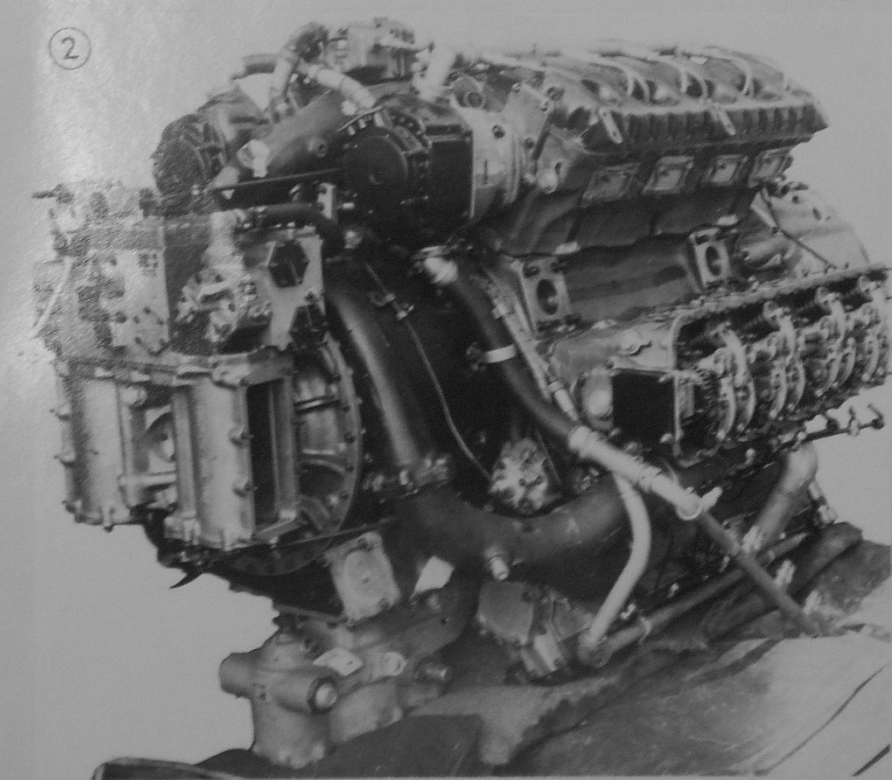
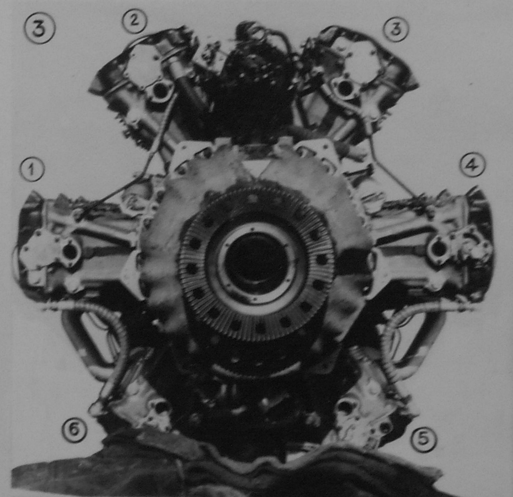
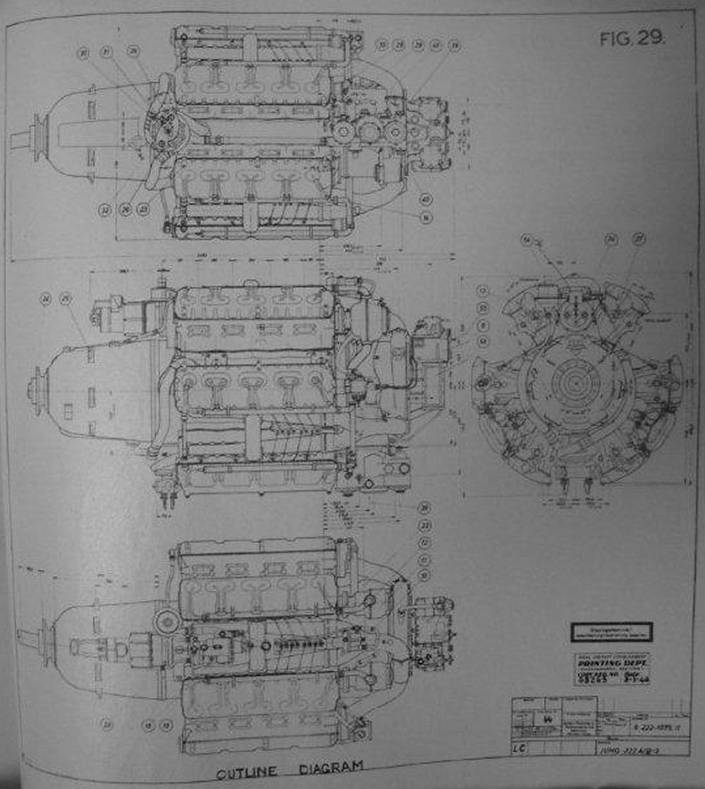
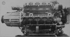
5. As will be seen from Figures 1 and 3, the engine is a combination of radial and in-line designs. The twenty-four cylinders are arranged in six banks of four, equally spaced at 60° around the crankcase. The engine may therefore be properly described as a 4-row 24-cylinder liquid-cooled radial. It is designed for mounting with a "vee” uppermost and an opposed pair of cylinder heads in the horizontal axial plane.
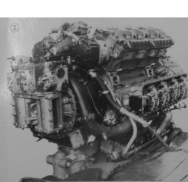
6. The four mounting points are arranged two on each side between the upper and the horizontal heads, as seen in Figure 2; the spaces between these heads are, for this reason, left unencumbered except for the exhaust pipes (not fitted). The crankcase is split as asymmetrically, the two bottom banks of cylinders being carried by what would normally be regarded as the sump of an in-line engine.
7. Deep ribs are formed around the long reduction gear housing, which may have bean deliberately extended to facilitate installation and cowling. The propeller shaft, which is co-axial with the crankshaft, terminates in a large, deeply-serrated flange (Fig. 3). The reduction gearing, which is presumed to be epicyclic, is reported to have a ratio of 2.714:1, but this has not been checked because of the risk of damage in turning a dry engine.
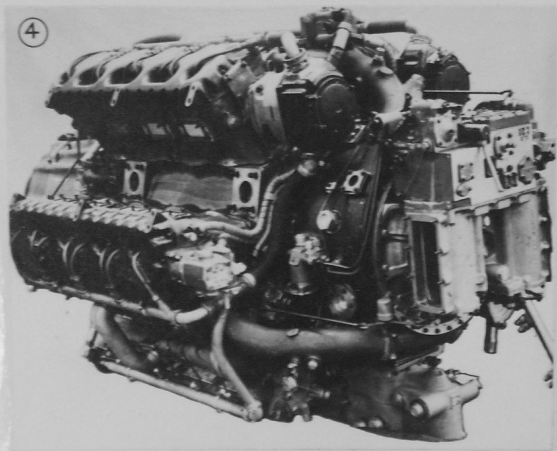
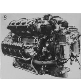
8. At the rear of the engine there is a compact circular wheelcase to the outer end of which is bolted the supercharger casing (Fig. 4).
9. The crankshaft and connecting rod arrangement have not yet been determined and will be described in a later report.
Dimensions
Length overall : 89.25"
Maximum diameter: 46.00"
Cylinders
11. The cylinder bore is 150 mm. This is the same as that of the Jumo 213. The stroke, and consequently the capacity, could not be obtained, but the capacity is obviously considerably greater than the 46.5 liters previously reported.
12. The six banks of cylinders are numbered clockwise from the front, No. 1 being the horizontal block on the left (Fig. 3). Propeller rotation is clockwise.
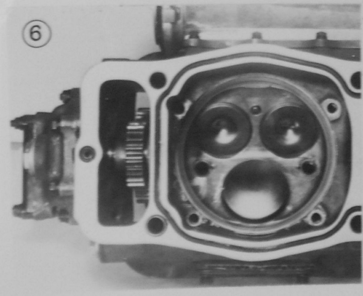
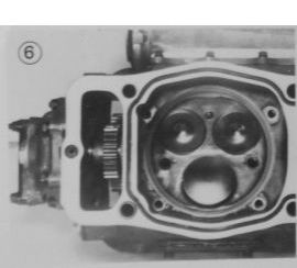
13. There are no separate cylinder blocks, the wet liner being mounted in the crankcase, which is ducted to permit circulation of the coolant. The cylinder head of each bank is detachable and forms the upper part of the liner coolant jacket. A rubber “necklace” makes a liquid-tight joint between the cylinder head and crankcase (Fig. 6). The lower end of each cylinder liner has a flange into which four waisted studs are screwed; these project through the cylinder head and serve to pull up the liner against a conical seating round the combustion chamber. An aluminium sealing ring interposed between the liner and the head makes a gas- and liquid-tight joint. The liner studs are sealed by small rubber rings and chamfered steel washers fitted between the nuts and the cylinder head.
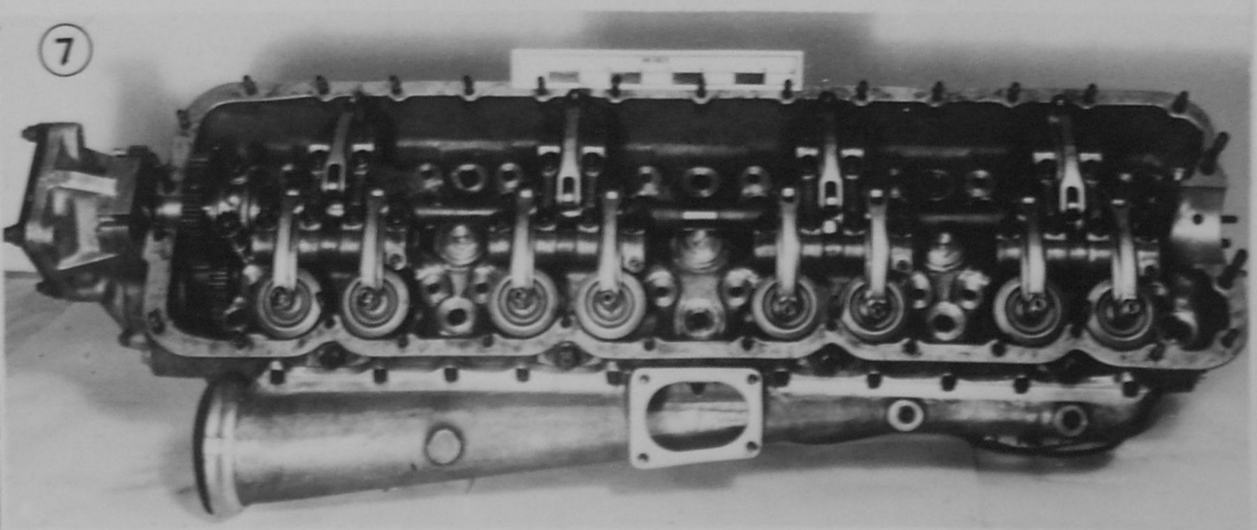
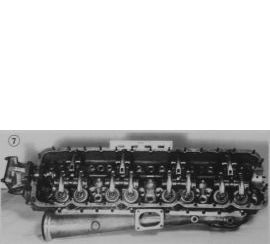
14. Each light-alloy cylinder head has an overhead camshaft driven from the rear of the crankshaft by a train of spur gears running on plain bearings. The camshaft runs in nine split bearings; the large rear bearing is adjacent to the driving gear and the smaller bearings are arranged in four groups of two, giving maximum support near the cams (Fig. 7).
15. There are two inlet valves, 55.3mm in diameter, and one sodium-cooled 63.5mm diameter exhaust valve per cylinder. Each valve has two large-diameter springs retained by conventional split taper-collets.
16. The valves are operated by light-alloy rocker arms mounted above the camshaft and pivoted centrally on small lay shafts (Fig. 7). The adjustable tappets have small self-aligning hardened steel tips that engage the valve stem pads. The rocker arms have hardened steel rollers running on the quick-lift cams.
17. Small serrated extensions at the front of the camshafts are utilised on the two lower heads to drive auxiliary oil scavenge pumps. Various auxiliaries are driven from the camshaft-operated gears of the different banks.
18. Each combustion chamber is of wide-angle asymmetrical pent-house shape and has the fuel injector mounted between the two inlet valves. The two phosphor-bronze sparking-plug inserts are diametrically opposed and are screwed and doweled into the casting (Fig. 6). The plugs are shrouded by aluminum tubes that push into the head and protrude through the camshaft cover, an oil-tight seal being formed by a rubber ring in the top of each tube.
19. The tapered induction trunks are of cast aluminium-bronze. There are three delivery trunks from the supercharger volute casing, each of which branches into two pipes and feeds two cylinder blocks. A balance pipe is fitted between the induction manifolds of numbers 1 and 6, 2 and 3, and 4 and 5 (Figs. 1 and 4). A rubber ring and quick-release clips provides a pressure-tight joint between each manifold and the induction trunk.
20. The coolant is circulated by a centrifugal impeller pump mounted below the crankcase at the forward end. Three delivery pipes lead the coolant to elbow joints bolted to the front of the crankcase between numbers 1 ad 2, 3 and 4, and 5 and 6 cylinder heads. A coolant outlet is provided at the front of each cylinder head (Fig. 3).
21. The camshaft and rocker arm mechanism is lubricated by oil fed under pressure to the top four banks of cylinders by pipes at the front of the heads. The oil from the two horizontal heads (Nos. 1 and 4) drains into the two lower heads (Nos. 5 and 6) through flexible pipes (Fig. 3) and lubricates the camshaft and rocker mechanism of these heads. Scavenge oil from the two upper heads drains via the rear train of gears into the crankcase. Auxiliary scavenge pumps mounted at the front of heads Nos. 5 and 6 returns the excess oil to the crankcase.
Supercharger
22. The 2-speed supercharger is driven by plain spur gears off the rear end of the crankshaft. The automatic change-over control is seen at the side of the wheel case in Figure 4. Two rectangular air intakes (Figs. 2 and 4) with “eyelid” type throttles lead the air through variable-pitch guide vanes into the eye of the impeller. A single aluminum-bronze casting forms the rear impeller bearing housing and air intake. The “Komandogurat” is mounted above this casting (Fig. 4).
23. Each of the three induction elbows has a priming connection for starting.
Fuel Injection System
24. There are three separate fuel injection pumps, one being mounted between numbers 2 and 3, one between 4 and 5 and one between 6 and 1 heads. Each pump feeds two banks of cylinders.
25. The fuel supply pump is driven off the rear of number 4 camshaft and supplies fuel under pressure to a unit mounted between numbers 2 and 3 heads, presumably a pressure-reducing valve; from this unit fuel is distributed to the three injection pumps.
Ignition
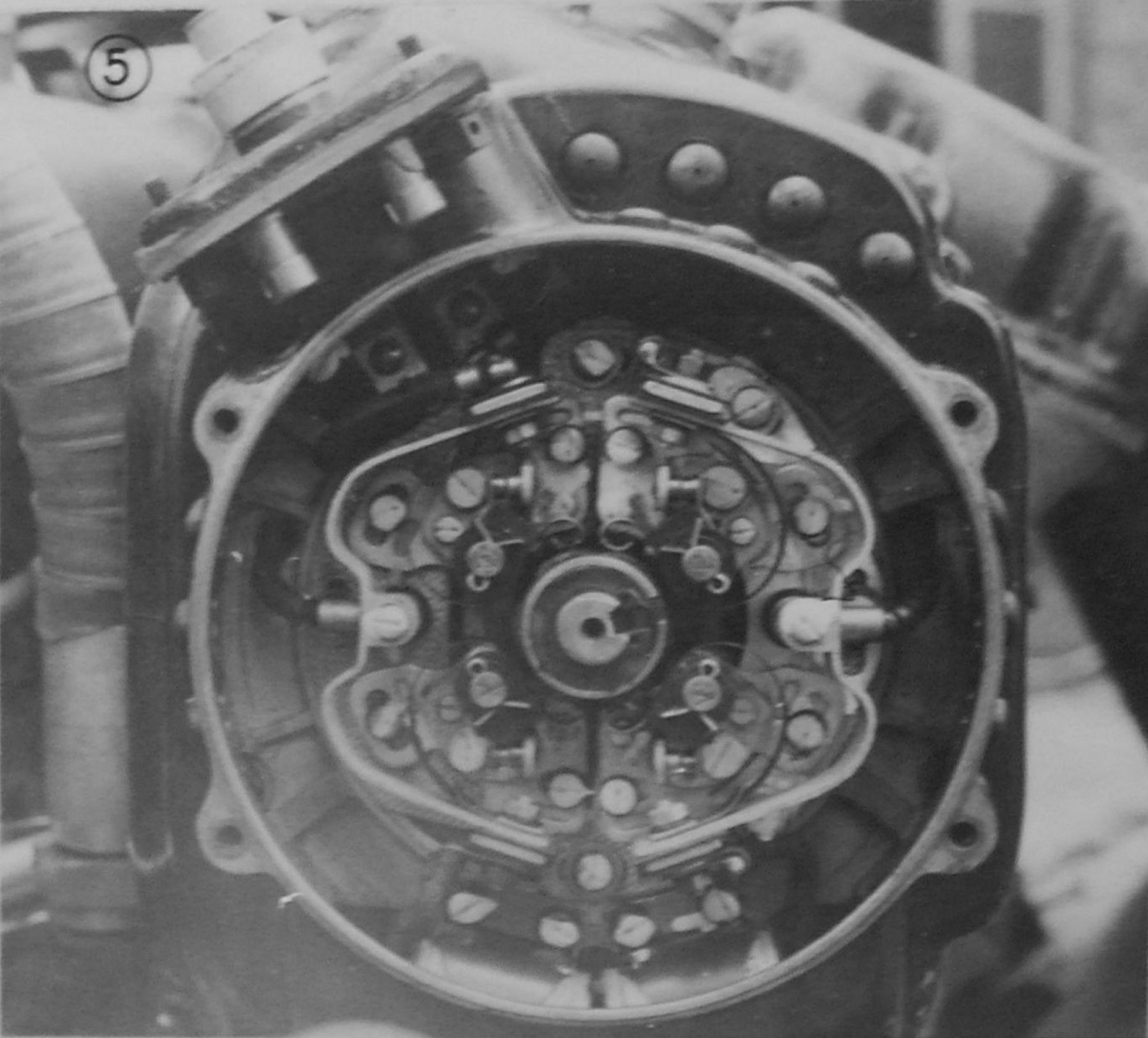
26. Two “duplex” magnetos are fitted. One is driven from the crankshaft driving gears of number 2 bank and serves Nos. 1, 2 and 6 cylinder banks; the second is driven off the camshaft gears of number 3 bank and serves the remaining banks. The magnetos and harness are fully screened. Each magneto has four contact breakers operated by a single 6-lobe cam of laminated plastic; these are readily accessible on removal of the end plates (Fig. 5). The cam followers are looped spring-steel strips.
Main Lubrication System
27. The pressure pump is mounted below, and driven from, the wheelcase. A self-cleaning metal disc oil filter is mounted in the rear of the oil pump housing, which also incorporates an adjustable pressure-relief valve. The main scavenge pump is apparently incorporated in the same housing as the pressure pump, and there is an auxiliary supply scavenge pump co-axial with the coolant pimp for draining the reduction gear housing.
Hydraulic Pump
28. This unit is driven from the rear of No. 5 camshaft.
Starter and Generator
29. The starter is mounted in an accessible position above the reduction gear housing (Fig.1), and turns-the crankshaft though a train of gears. Engagement of the starter is by a solenoid-operated mechanical linkage.
30. The generator is mounted between numbers 2 and 3 banks and is driven off the same train of gears.
Tachometer Drive
31. The revolution counter is driven from a small gear-case mounted on the main wheelcase adjacent to the rear of number 1 cylinder bank.
Power Output
32. The power output of the Jumo 222 has been reported by P's/W [sic; prisoners of war] as between 2,400 and 3,000 hp for take-off and 1,800 ~ 2,400 hp at a rated altitude of about 18,000 ft.
In view of the increased cubic capacity, however, these figures may have been exceeded.
Signed by G.E.F Proctor, Wing Commander, A.I.2.(g), D. of I.(R), 18 April, 1945
| |
 |
|
| |
Fig. 1 |
|
 |
 |
 |
| Fig. 2 |
Fig. 3 |
Fig. 4 |
 |
 |
 |
| Fig. 5 |
Fig. 6 |
Fig. 7 |
Examination of Junkers Jumo 222
24 Cylinder Radialine Aero Engine
Report No: F.A. 271/1 (Excerpts)
By F/LT LW Richards, B.Sc (Eng) A.M.I.Mech E. A.M.I.E.E.
And the Staff of Gas Dynamics Department
Royal Aircraft Establishment, Farnborough
Submitted by Tom Berthold
1. Introduction
A Jumo 222 engine was received from A.I.2(g( for strip and examination. In this report the general construction and outstanding features are described. This engine was found at an assembly plant near Frankfurt-on-Main. It was the first engine of this type to be captured and no details of the installation are as yet confirmed although it has been mentioned in connection with the DO.435, He.177, F.W.191 and Ju.288 aircraft as well as a flying test bed version of the Ju.52 (probably Ju52/3m modified). When received at this Establishment the engine was incompletely assembled, several pipes and details being missing, and the engine cannot be rotated.
2. General Description
The Jumo 222 is a 24 cylinder liquid-cooled supercharged engine having 6 blocks of 4 cylinders each, disposed radially about the crankcase and giving a 4 row radial of 6 cylinders per row. It can conveniently be designated as a "Radialine" engine.
The single-stage, two-speed supercharger is mechanically driven.
Three direct fuel injection pumps are mounted between alternate cylinder blocks while auxiliary drives are taken from an intermediate gear casing mounted towards the rear of the engine. This gear casing encloses the two-speed supercharger drive gears as well as the change-speed mechanism. The supercharger is mounted on a rear casing, mounted on the intermediate casing. The master control box is mounted above the supercharger intakes.
Each cylinder has one exhaust and two inlet valves of the poppet type which are operated by a single camshaft on each cylinder block. The camshafts are driven by trains of spur gears from the crankshaft.
The airscrew reduction gear are of epicyclic type and provision is made for the fitting of a Junkers type airscrew on a Hirth type radially splined coupling.
It has been ascertained from German documents that this engine is a Junkers Jumo 222 B-2 with right-hand rotation and 140 x 135 mm bore and stroke with 2-speed single-stage supercharger.
The mounting points on the engine consist of four feet cast integral with the crankcase which hold the airframe-to-engine mountings by spigots and studs. To date there are no details of airframe mounting but in all probability rubber-cushioned mounting to forged bearers with the Junkers type ball joint on the engine-to-airframe pick-up-points are used.
Appendix I Junkers Jumo 222 B-2 Engine Specifications
General Engine Specifications
Type of Engine: Supercharged, geared, pressure liquid cooled "Radialine" engine fitted with 2 speed supercharger; direct fuel injection and single lever control box. Junkers type airscrew with Hirth type radial-splined coupling.
Number of Cylinders: 24
Arrange of Cylinders: 6 blocks of 4 cylinders each, disposed about a radial type crankcase giving a 4 row radial of 6 cylinders per row.
Bore: 140 mm
Stroke: 135 mm
Swept Volume: 2,124 cc
Clearance Volume: 370 cc
Total Capacity: 50.976 l
Compression Ratio: 6.735:1
Propeller Reduction Gear Type: Epicyclic Ratio: 0.3667
Supercharger Specifications
Type: Centrifugal with fully shrouded impeller, single stage, 2 speed
Number of Swirl Vanes: 12
Hub Diameter: 2.4"
Eye Diameter: 7.725"
Eye Area: 42.5 in²
Entry Guide Vane Angle, Tip: 78°
Entry Guide Vane Angle, Root: 58°
Number of Impeller Blades: 16
Impeller Tip Diameter: 12.784"
Impeller Tip Width: 0.585"
Impeller Tip Area: 22.1 in²
Number of Diffuser Vanes: 15
Diffuser Throat Area: 10 in²
Drive Gear Ratio, M: 6.7
Drive Gear Ratio, S: 9.16
Appendix II
Translation from Captured German Paper of Particulars of the Jumo 222 Series Engines
1. Jumo 222 Series Specifications
Type: Liquid cooled 4-stroke Otto cycle aero engine with petrol injection.
Cylinder Arrangement: 24 cylinder arranged as a 6 cylinder, 4 bank radial
Crankshaft Rotation: Right in direction of flight
Propeller Shaft Rotation and Gear Ratio: A-C-E - Left, 2.727:1; B-D-F - Right, 2.73:1
Compression Ratio: 6.5:1
2. Jumo 222 Model Specifications
2.1 Jumo 222 A/B-1
Bore: 135 mm
Stroke: 135 mm
Cubic Capacity: 43.3 l
Maximum RPM: 3,200
Supercharger: single stage, 2 speed
Stage of Development: Zero series finished
2.2 Jumo 222 A/B-3
Bore: 140 mm
Stroke: 135 mm
Cubic Capacity: 49.9 l
Supercharger: single stage, 2 speed. New supercharger fitted increasing maximum boost rated altitude to 5-6km.
Further development of 222 A/B-3 to give higher power through increased rpm and increased swept volume.
Stage of Development: Planned to be series built but series engine not yet available.
2.3 Jumo 222 C/D
Bore: 145 mm
Stroke: 135 mm
Cubic Capacity: 55.44 l
Maximum RPM: 3,200
Stage of Development: Design finished, first prototype engine are being built
2.4 Jumo 222 E/F
Bore: 140 mm
Stroke: 135 mm
Cubic Capacity: 49.9 l
Maximum RPM: 3,000
Further development of 222 A/B-3 to give higher power by introducing a 2-stage supercharger. The first stage is driven by a mechanical gear. The second stage by infinitely variable hydraulic drive. Charge cooler as heat exchanger (air-water)? (This is a literal translation, it may mean that the charge cooler is liquid cooled, which in turn is air cooled).
Maximum boost altitude: 11km
Stage of Development: 6 prototype engines finished with a further 4 in production. Altitude test bed tests give the maximum boost altitude as 9km. Further development of supercharger for 11km.
2.5 Jumo 222 Turbo
The first engines were built on the basis of 222 A/B-1 or A/B-2; later on basis of A/B-3. The first stage was a Boraig turbo compressor.
State of Develoment: Accomplished, together with tests of 22 B-2-22 on the ground level test beds.
2.6 Jumo 225
Bore: 135 mm
Stroke: 135 mm
Cubic Capacity: 69.5 l
Maximum RPM: 3,000
Takeoff Power: 3,500 bhp
A further development of the Jumo 222 by the addition of 12 cylinders arranged in 2 banks of 6 cylinders each.
Stage of Development: Design stopped before completion.
3. Jumo 222 Series Test Data
Fuel: 87 Octane
Fuel Pressure: 1.7 ±0.2 Atu (ground level)
Fuel Capacity: 2 x 1,500 l/hr
Lubrication: Aero Shell "Medium" on "Intarn Hotring". Short main stream lubricating oil flow with secondary supply from header tank. Main pump supplies 8,500 l/hr at 2,700 rpm; Secondary pump supplies 2,600 l/hr at 2,700 rpm.
Oil Temperature: 105°C Maximum
Oil Consumption: 9 g/bhp/hr at 2,500 rpm; 14 g/bhp/hr at 3,000 rpm
Heat Transfer, Climb and Combat, Jumo 222 A/B: 65,000 cal/hr over 2 oil heat exchangers.
Heat Transfer, Climb and Combat, Jumo 222 E/F: 210,000 cal/hr over 3 oil heat exchangers, including oil from the hydraulic supercharger coupling and charge air-water cooler in an extra circuit of 85°C.
Coolant: Main Flow, with a secondary feed from a header tank.
Coolant Circulating Quantity at 2,500 rpm: Main Flow = 13-14 l/sec; Secondary flow = 16-0.7 l/sec
Coolant Temperatures, Jumo 222 A/B: Regulated to 100°C at all altitudes, 120°C maximum for short periods, takeoff and taxiing.
Coolant Temperatures, Jumo 222 E/F: Main flow near ground level = 120°C; at rated altitude = 105°C. Secondary flow at all altitudes = 85°C.
Engine Capacity: Approximately 60 l
4. Weights (Dry, kg)
| | Jumo 222 A/B | Jumo 222 E/F |
|---|
| LH Rotation | 1,100 | 1,210 |
| RH Rotation | 1,125 | 1,240 |
| Auxiliaries Including Oil and Charge Coolers | 120 | 155 |
| Total, LH Rotation | 1220 | 1365 |
| Total, RH Rotation | 1245 | 1395 |
5. Jumo 222 Power Data
| | 222 A/B-1 | 222 A/B-2 | 222 A/B-3 | 222 C/D | 222 E/F | 222 Turbo |
| Takeoff and Emergency | 2,500 | 2,500 | | 2,500 | | 3,000 | 2,500 | 1,920 | 2,400 | 2,070 |
| Height, km | 0 | 0 | | 0 | | 0 | 0 | 9 | 0 | 12.3 |
| RPM | 3,200 | 2,900 | | 3,000 | 3,200 | 3,000 | 3,000 | 3,200 | 3,200 |
| Climb and Combat | 2,200 | 2,250 | 2,020 | 2,230 | 1,900 | 2,600 | 1,780 | | 2,170 | 1,970 |
| Height, km | 0 | 0 | 5 | 0 | 6 | 0 | 0 | | 0 | 12.6 |
| RPM | 2.900 | 2,700 | 2,700 | 2,700 | 2,700 | 2,900 | 2,900 | | 2,900 | 2,900 |
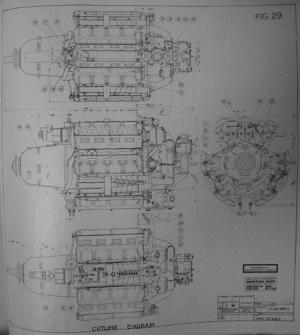
Jumo 222 Outline