Angle’s Engines
Aircat, LeBlond, Rearwin, Ken-Royce, Velie, Lambert and Angle A-1
Compiled by Kimble D. McCutcheon
Published 20 Nov 2019; Revised 21 Nov 2919
Unless otherwise stated, images are from Aerosphere 1939
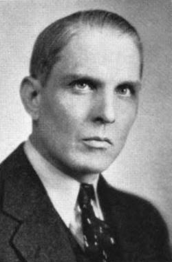
Glenn D. Angle
(The Michigan Alumnus 1940) |
Glenn D. Angle (5 Jan 1891 26 Jan 1966) was born in Imlay City, Michigan, spent his early life in Pontiac, and after a two-year stint with the Welch Motor Car Company, entered the University of Michigan on an American Institute of Architects scholarship. After a year, he switched to mechanical engineering. Upon graduation, he then reentered the automobile industry as a designer for the Oakland Motor Car Company and the Studebaker Corporation. For a time, he was chief engineer for the Dort Motor Car Company.
In 1916, Angle joined the Curtiss Aeroplane and Motor Corporation, in charge of engine design. From 1917 until 1924, at McCook Field near Dayton, Ohio, Angle was head the U.S. Army Air Service Power Plant Section Engine Design Branch. Angle reported to Major George E.A. Hallet and was assisted by Theos E. Tillinghast and W.O. Warner.
During his tenure at the Engine Design Branch, Angle oversaw one of the most productive aircraft engine design periods ever. Numerous new engines were designed in-house, and the Engine Design Branch worked closely with several engine manufacturers, doing extensive development and testing. The group designed and built a universal test engine, which facilitated testing of cylinders with various bores and strokes. Angle supervised the development of the Air Service W-1 and W-2 aircraft engines, both of which were 18-cylinder "W" configurations intended to exceed 1,000 hp.
Angle left the Air Service in 1924 to organize the Detroit Aircraft Engine Works and eventually LeBlond Aircraft Engine Company, both of which are described in more detail below. From 1934 until 1935, Angle was in charge of the Winton Engine Company design division. Starting in 1935, Angle was a consulting engineer, professor of mechanical engineering, and continued to push engine design boundaries of for the remainder of his life.
In 1921, Angle published his Aircraft Engine Encyclopedia, which was meant to be a catalog of all the world's aircraft engines. This was followed in 1925 by Engine Dynamics and Crankshaft Design. Angle was technical editor of Aero Digest for eight years, and published more than 50 articles for magazines and newspapers. Starting in 1940, Angle edited Aerospheres 1939, 1941, 1942 and 1943, which now included aircraft, engines, tools, equipment and component descriptions and advertisements.
Angle was affiliated with Alpha Tau Omega, an Institute of Aeronautical Sciences Associate Fellow, and a Eugine Field Society member. |
The Aircat
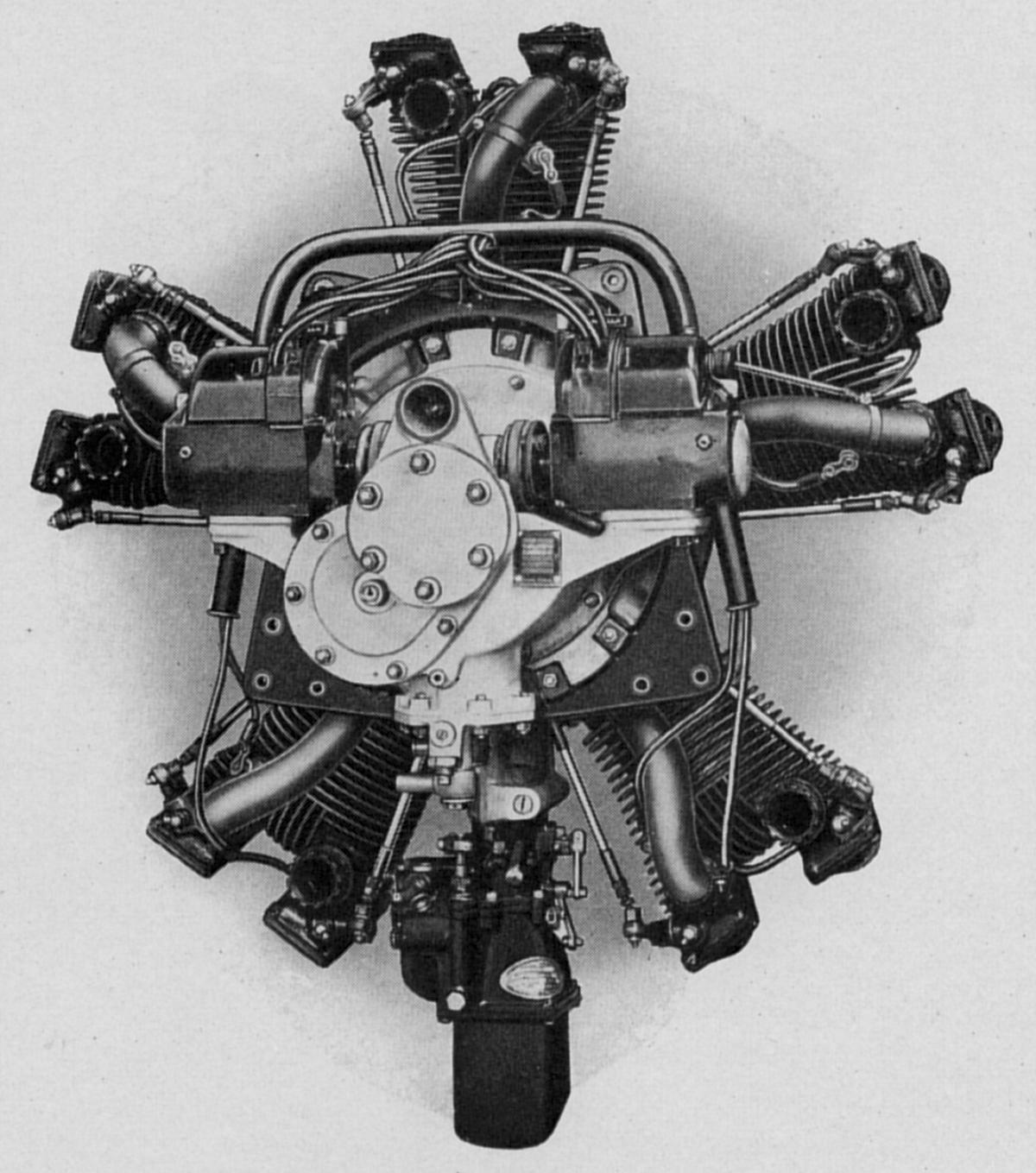
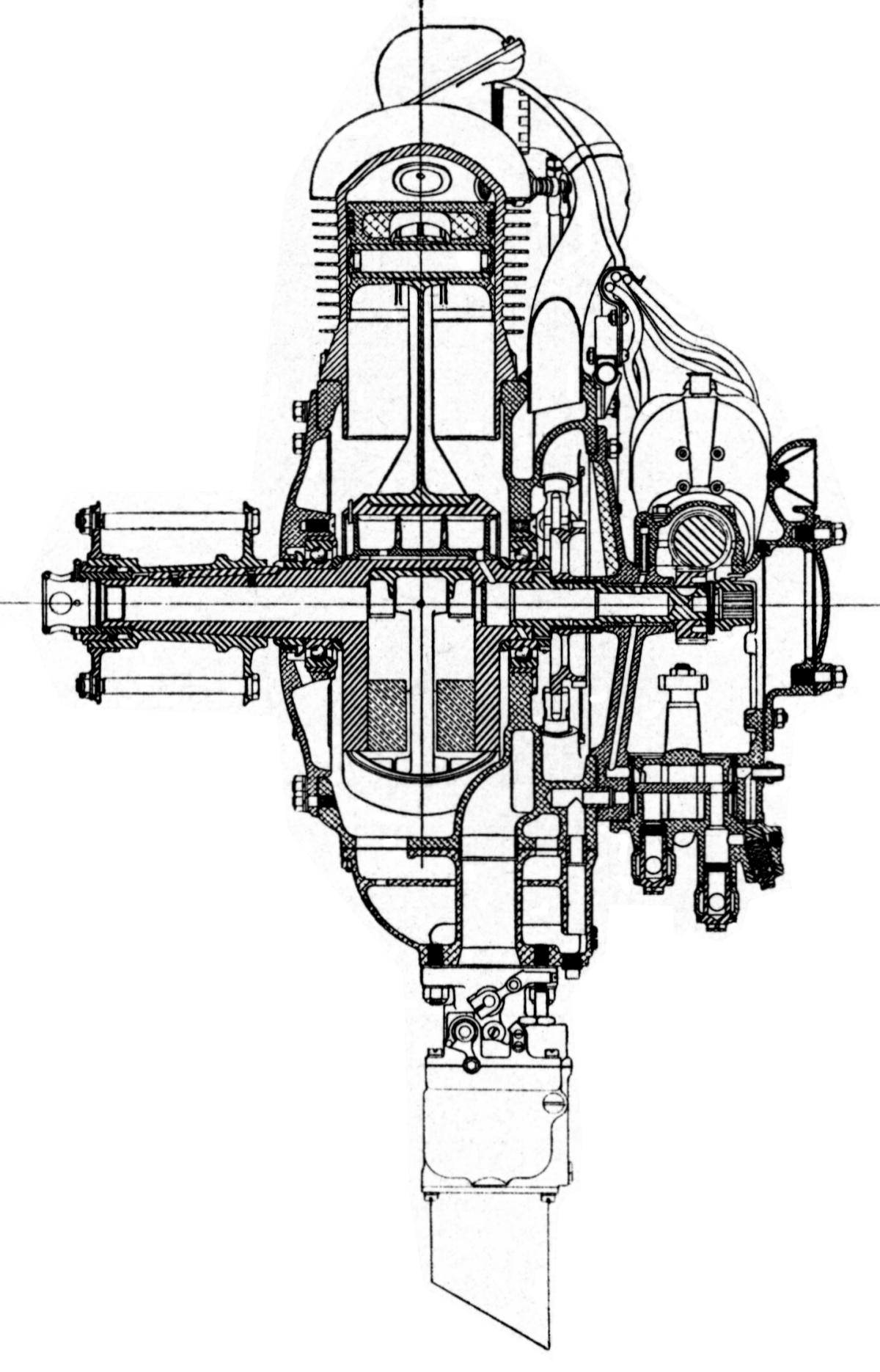
During his time with the U.S. Army Air Service, Angle designed the Aircat, a small 5-cylinder air-cooled radial with a 4.125" bore and 3.5" stroke, displaced 233.9 in³ and weighed 230 lb. Output was 60 hp at 1,800 rpm and 80 hp at 2,400 rpm. Cylinders were cast from nickel-iron with integral cooling fins and featured two inclined valves that seated directly on the hemispherical cylinder head (no valve seats). These were actuated by exposed push rods and rocker arms. A Zenith Model 76 carburetor and two Scintilla AP-5 magnetos were used.
In 1924, Capt Eddie Rickenbacker, who was America's top WWI fighter ace, persuaded Angle to join him in Detroit to complete development of the Aircat. A disagreement over patent rights with the president of Rickenbacker Motors resulted in Angle and Rickenbacker, establishing a shop called the Detroit Aircraft Engine Works in a Warren Avenue warehouse. From October 1925 until May of 1926, about ten Aircat engines were built. One was installed in a Driggs C3 testbed; several were sold to Don Luscombe for use on Monocoupes, and at least one to another buyer.
In early 1927 the Aircat operation was sold to Hugo Black, owner of Peninsular Products Company in Detroit, who moved it to a new plant and renamed it the Detroit Aircraft Engine Corporation. The "production" Aircat was identical to the prototypes, except that the stroke had been increased to 3.75" for a 250.6 in³ displacement.
 |
 |
|
| Fore |
Left |
| Detroit Aircat |
LeBlonde
Before Aircat production actually began, the R.K. LeBlond Machine Tool Company of Cincinnati, Ohio bought the Detroit Aircraft Engine Company assets and created the LeBlond Aircraft Engine Corporation. LeBlond engaged Glenn Angle to design a new cylinder, which, along with a few other minor changes, resulted in the 5-cylinder LeBlond 60 5D. With a compression ratio of 5.35:1, an output of 65 hp at 1,950 rpm, and a weight of 228 lb, this was the first small engine to pass a Navy type test; it also received Department of Commerce approved Type Certificate No. 12.
Model 5D cylinders were nickel-iron castings with integral cooling fins. Intake and exhaust valves, inclined at 30° from centerline, were operated by push rods and rocker arms; the intake valves seated directly into the hemispherical combustion chamber while the exhaust valves had molybdenum-iron seats. Intake valve guides were cast iron, while the exhaust guides were high-speed steel. Volute valve springs were used and the valve mechanism was covered by a pressed steel cap.
Aluminum alloy pistons were cast in permanent molds. Two compression rings and one oil scraper ring were located above the wrist pin. The master rod had a removable cap whose bolts also locked the link rod knuckle pins. Both master and link rods were H-section alloy steel drop-forgings.
The crankshaft was a completely finished alloy steel forging with a bronze counterweight. A removable aluminum plug inserted into the hollow crankpin routed lubricating oil that entered through the hollow aft crankshaft journal to the master rod bearing. The crankshaft ran on two ball bearings, with the front one fixed in the front crankcase cover and the rear one supported in a steel sleeve, which left it free to move slightly fore-and-aft.
The crankcase was a heat-treated aluminum alloy casting with an integral induction ring for charge circulation, which in conjunction with steel pipes that fed each cylinder. An oil sump collected scavenge oil for return to the oil tank. A Stromberg carburetor, heated by the scavenge oil, provided the induction mixture. Roller cam followers ran in cast iron bushings pressed into crankcase bosses.
When the LeBlond 60 5D was assembled, the crankshaft and connecting rods were assembled and inserted through the crankcase front. An aft gearcase was independently attached. The gearcase could be removed and replaced without disturbing valve or ignition timing.
The gearcase was cast from aluminum and featured brackets to which magnetos were mounted. Both Bosch and Scintilla magnetos were accommodated. An oil pump combined pressure and scavenge functions along with filter screens and adjustable pressure relief.
 |
 |
 |
 |
 |
| Fore |
Aft |
Fore |
Left |
Aft |
| LeBlond 60 5D |
The 5-cylinder, 85 hp at 2,125 rpm, 222 lb, LeBlond 85 5DF, was an improved 60 5D, but with a 4.25" bore, 3.75" stroke, it displaced 266.0 in³. It received Approved Type Certificate No. 46 on 8 Apr 1930. Its newly-designed 5.4:1 compression ratio cylinders featured forged steel barrels that were machined all over. Cast Y-alloy aluminum cylinder heads with aluminum-bronze valve seats were attached to the cylinder barrel with 12 studs and without any gasket. Separate cast-aluminum rocker boxes enclosed the rocker arms and valve gear. Two Bosch FU-5 or Scintilla SB-5 magnetos furnished ignition, and a Holley Model 429 carburetor provided mixture. A third crankshaft main bearing was employed, which in combination with the new cylinder and head, greatly improved reliability. On 29 Jun 1936, ATC No 46 was modified to add Scintilla PN-5D magnetos and a Stromberg NAR-3 carburetor to the equipment list. A further type certificate modification on 16 October 1938 incorporated an optional new cylinder head, cylinder barrel, piston and valves, along with a compression ratio increase to 6.1:1 and 73 octane gasoline; this was the Leblond 85 5F. On 16 Nov 1936, ATC No. 46 was again altered, raising the rated power to 90 hp at 2,250 rpm on 65 octane fuel; compression ratio was 6.1:1 and weight was 222 lb.
 |
 |
| Fore |
Aft |
| LeBlond 85 5DF |
The LeBlond 70 5DE, was another improved 5D, with the same bore, stroke and weight. However, the cylinders were similar in design to the 5DF and used many of the same valve mechanism. The 70 5DE produced 70 hp at 1,950 rpm and was awarded Approved Type Certificate No. 48 on 3 May 1930. Scintilla PN-5D magnetos were added to the equipment list on 9 May 1936, and on 1 Aug 1936, a Model 5E with a 5.4:1 compression ratio was added to the ATC No. 48.
 |
 |
| Fore |
Aft |
| LeBlond 70 5DE |
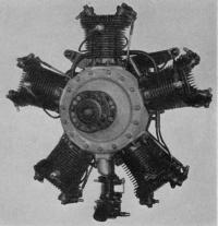
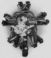
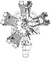
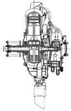
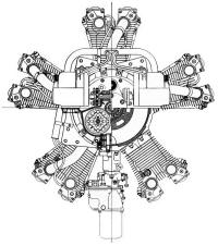
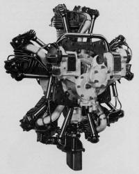
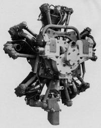
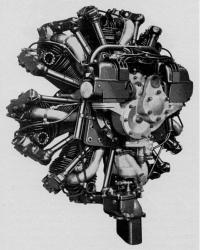
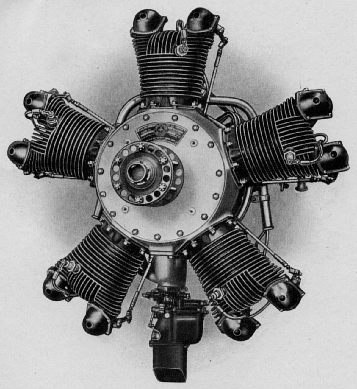
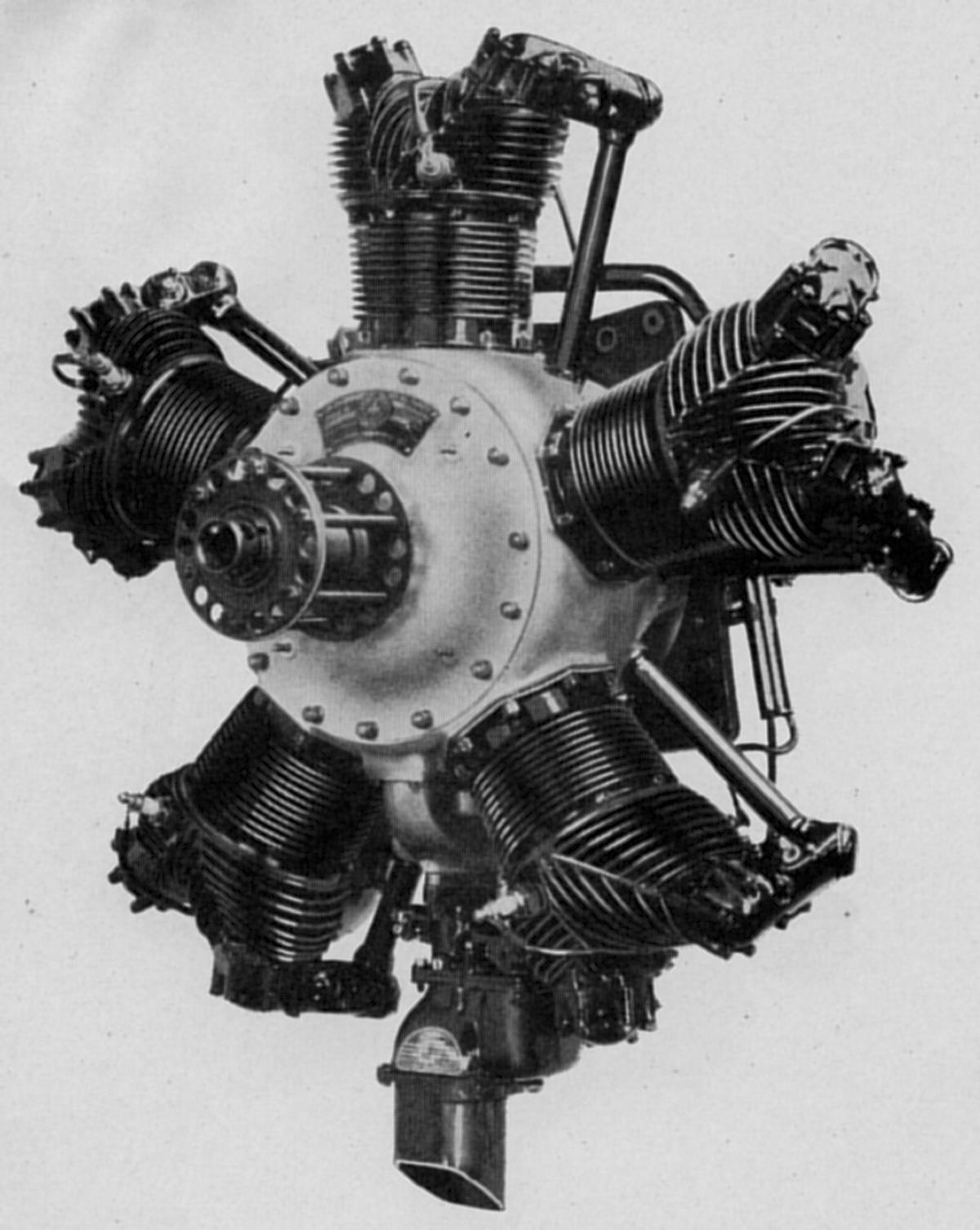
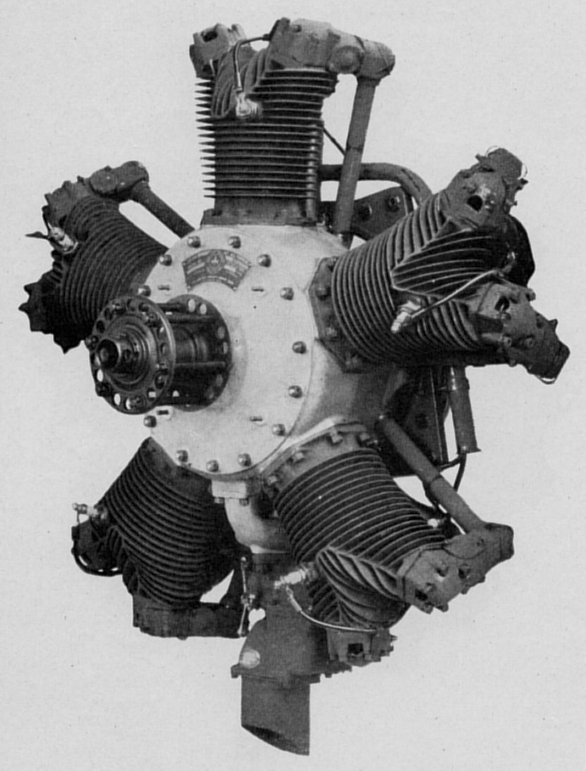
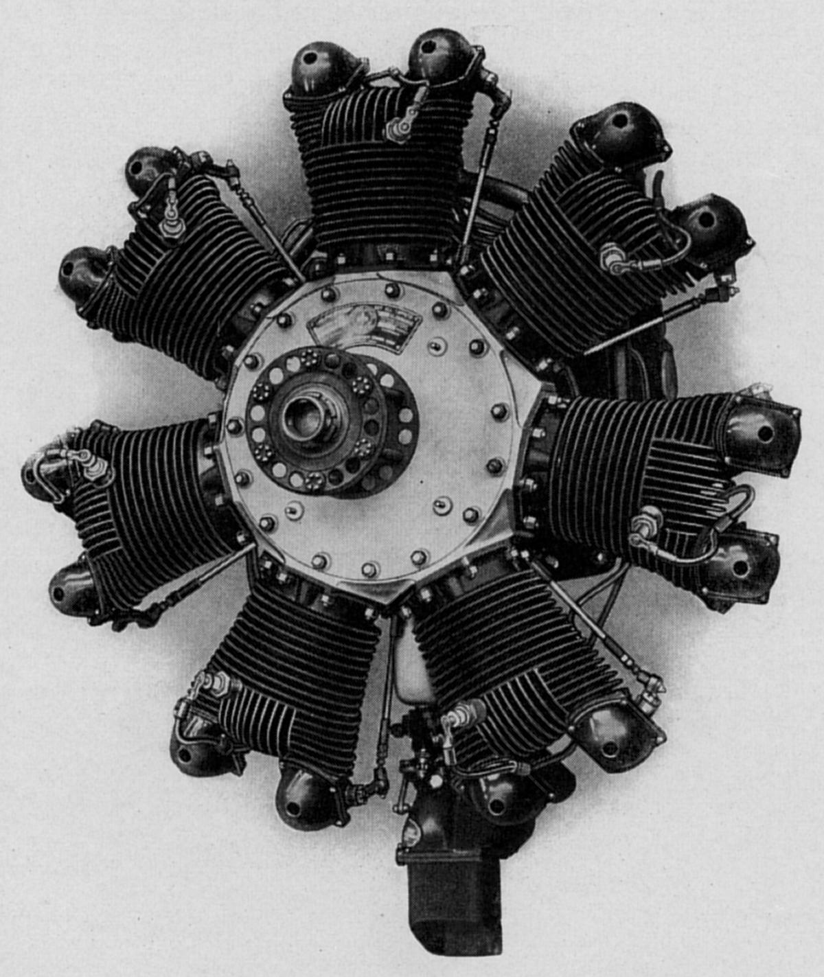
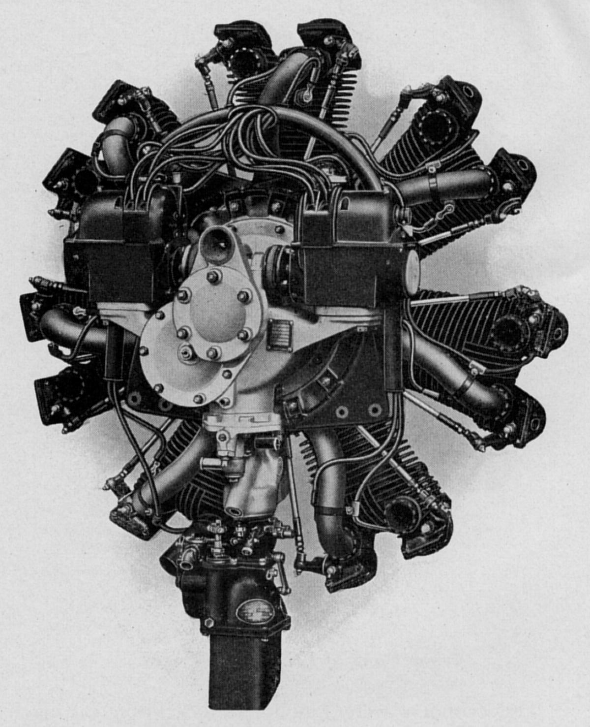
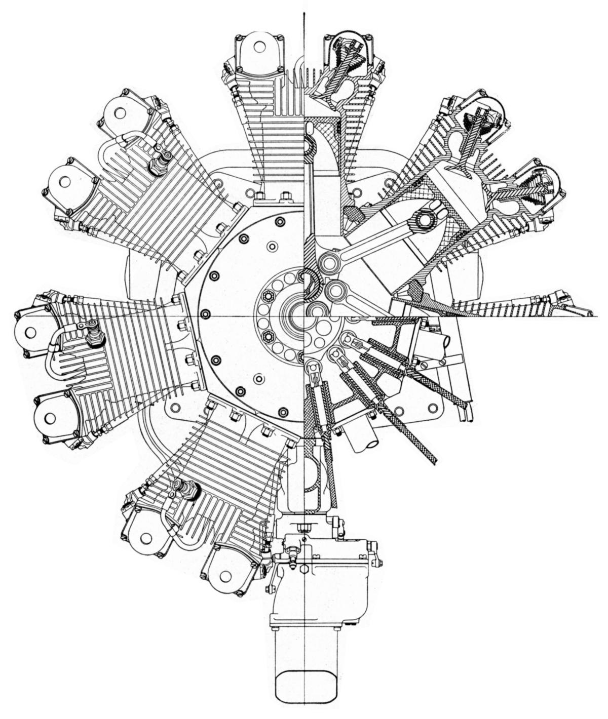
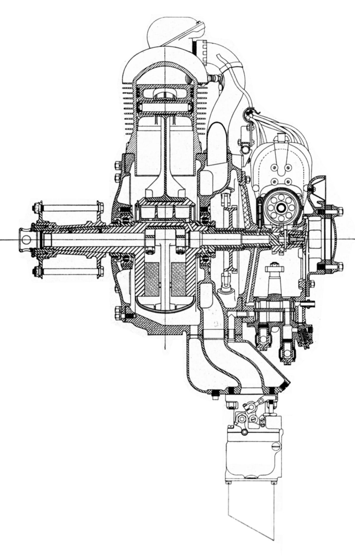
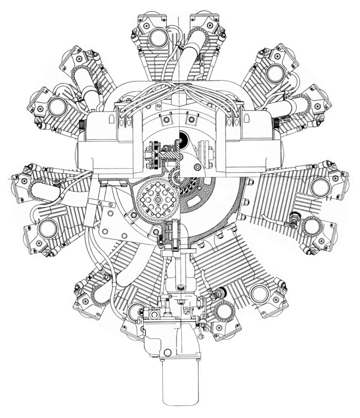
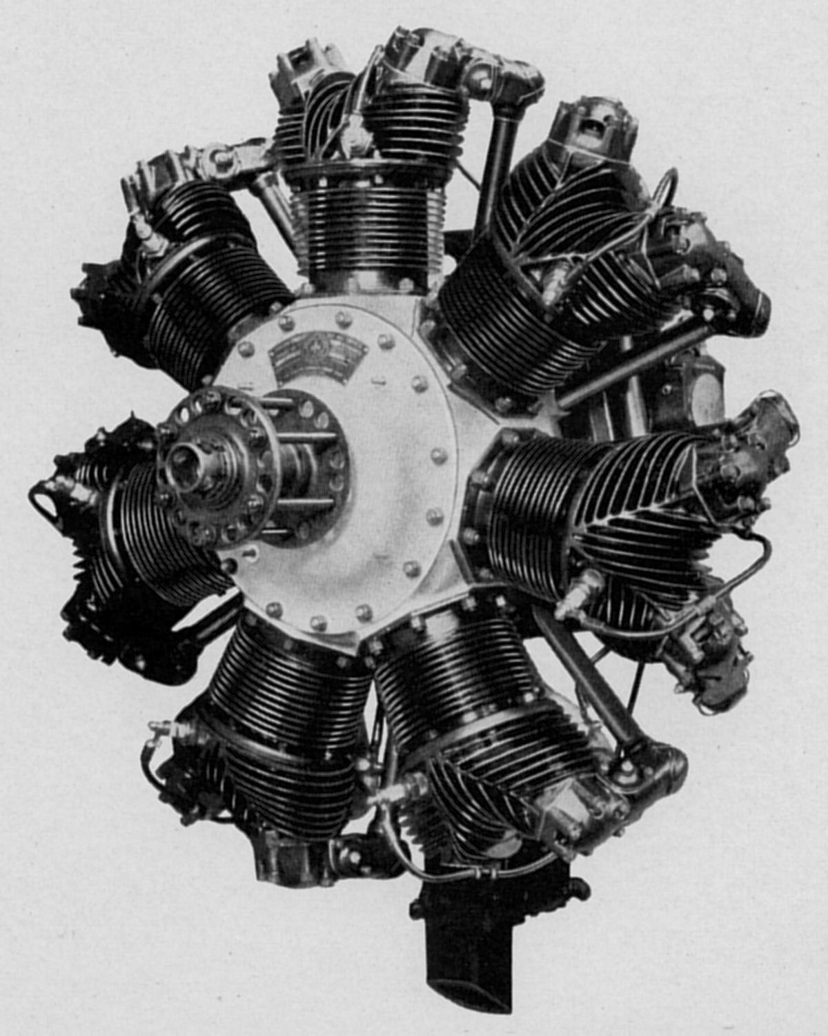
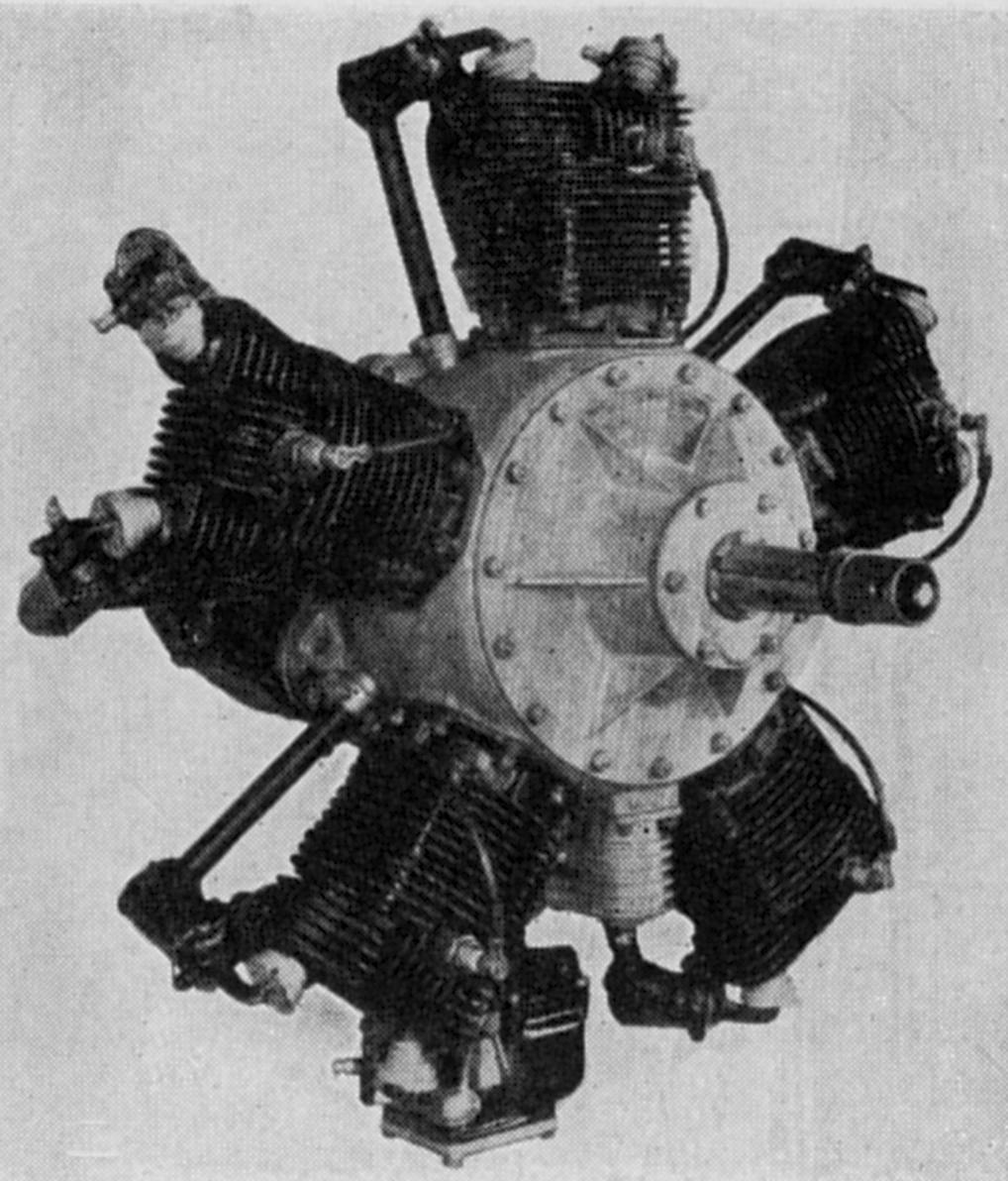
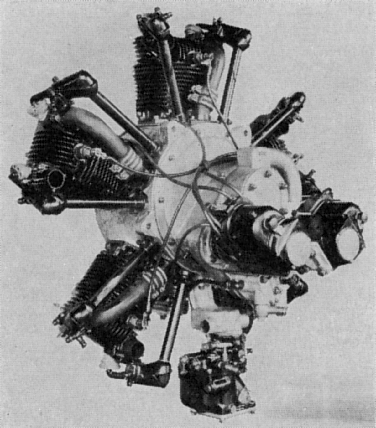
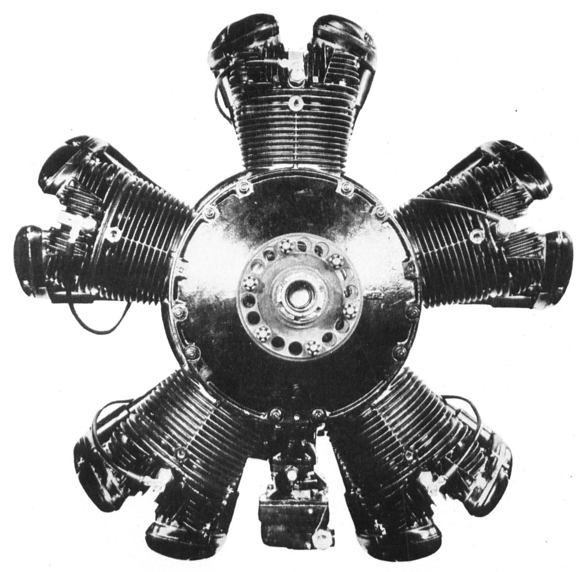
The 7-cylinder, 291 lb LeBlond 90 7D was built from many 5D parts. With the same 4.125” bore and 3.75” stroke, it displaced 350.8 in³. Producing 90 hp at 1,975 rpm with a 5.35:1 compression ratio on 70 octane fuel, it was awarded Approved Type Certificate No. 20 on 6 Feb 1929. It used dual Scintilla MN7-D magnetos and a Stromberg NA-R3 carburetor.
 |
 |
 |
 |
 |
| Fore |
Aft |
Fore |
Left |
Aft |
| LeBlond 90 7D |
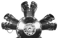
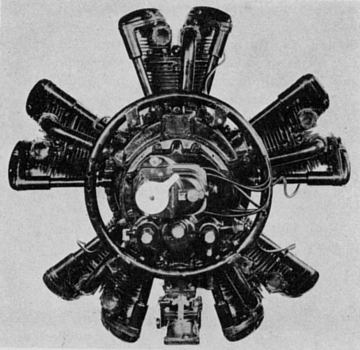
The 110 7DF, with a 4.25” bore, 3.75” stroke, displaced 372.4 in³ and used the same cylinders as the 5DF. Weighed only 275 lb, it produced 110 hp at 2,150 rpm with a 5.4:1 compression ratio and using 70 octane fuel. It could use either a Stromberg NA-R3 or Holley 429 carburetor and ignition was furnished by two Scintilla MN-7D magnetos. It received ATC No. 52 on 31 May 1930.
 |
 |
| Fore |
Aft |
| LeBlond 110 7DF |
R.A. Rearwin of Kansas City, Kansas purchased the LeBlond engine business during the last week of 1937 and continued producing the LeBlond 5E, 5F and 7DF designs as the Ken-Royce Aircraft Engine Company, named after Rearwin's sons. The later Ken Royce 90 5G was the same as the LeBlond 90 5F, but incorporated automatic valve gear lubrication.
The 282 lb Ken Royce 120 7F produced 120 hp at 2,225 rpm on 73 octane fuel with a 6.1:1 compression ratio. It used either a Stromberg NA-R3 or Holley 429 carburetor, and Scintilla MN-7D magnetos. The 285 lb 120 7G featured automatic valve gear lubrication.
Rearwin ceased production at the start of WWII and did not resume after the war.
Velie
No discussion of Glenn Angle's engines is complete without including the Velie story. The Mono-Aircraft Corporation (Don Luscombe), which had bought several Aircat engines, was dissatisfied with its reliability and availability. Mono-Aircraft Corporation persuaded Velie Motors Corporation of Moline, Illinois to essentially copy the Aircat. Velie received Approved Type Certificate No. 4 covering its M-5 engine on 22 Jun 1928. LeBlond, which then owned the rights to the Aircat, sued Velie for patent infringement and was awarded damages. After the demise of Velie, the engine line continued under the name of Lambert Engine and Machine Company.
The Velie M-5 was an air-cooled 5-cylinder radial with a 4.125" bore, 3.75" stroke and 250.6 in³ displacement. Initially producing 45 hp at 1,750 rpm, it was upgraded to 55 hp and finally 65 hp at 1,900 rpm. It had a 5.2:1 compression ratio and 240 lb weight. M-5 cylinders were cast from nickel-iron with integral cooling fins. A cast aluminum alloy cylinder head with aluminum-bronze valve seats was employed. Cylinder barrels and heads were held to the crankcase with four long studs. The two-piece crankshaft ran on three ball bearings. Two Scintilla magnetos and a Stromberg NA-R3 carburetor were employed.
 |
 |
| Fore |
Aft |
| Velie M-5 |
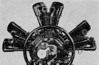
The Angle A-1
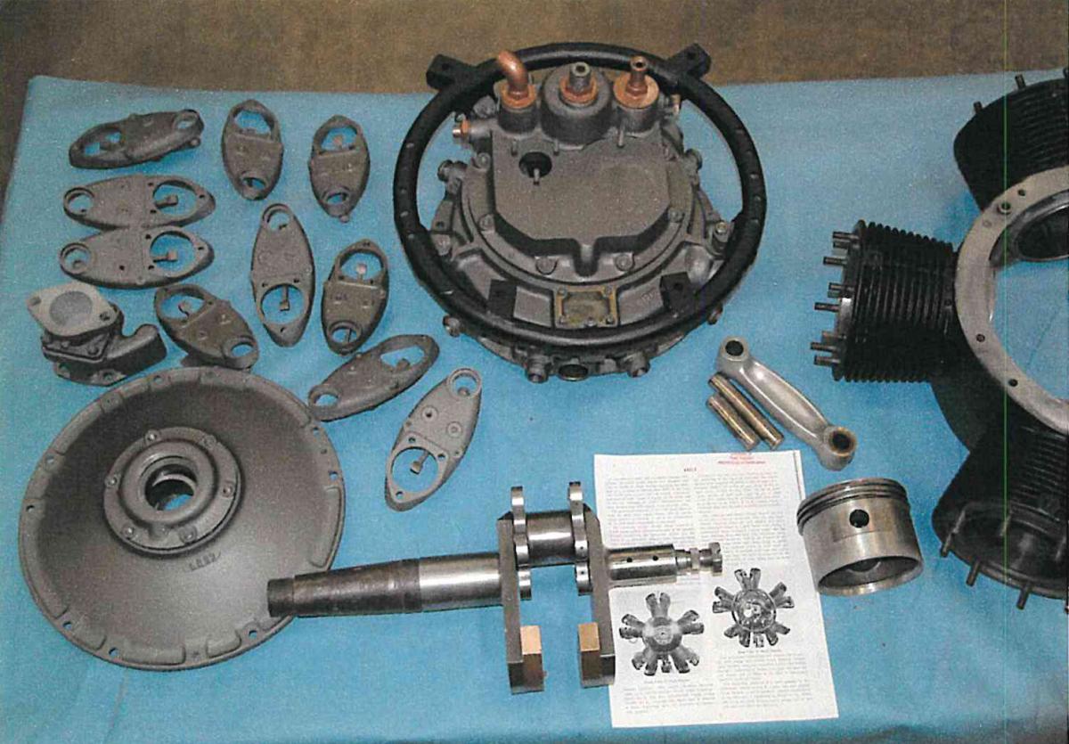
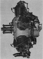
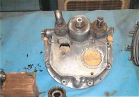
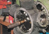
Supported by another group of Detroit investors, Glenn D. Angle designed an experimental 5-cylinder radial during 1939, which departed substantially from typical light aircraft engine design practice; it was the culmination of all Angle had learned about engine design. It was intended for simple assembly and repair, ruggedness and low-cost. With a 4.125" bore and 2.75" stroke, it displaced 183.8 in³ and produced direct-drive outputs ranging from 50 hp at 1,950 to 60 hp at 2,300 rpm to 70 hp at 2,650 rpm. With propeller reduction gearing, it was capable of 80 hp at 3,000 rpm, 90 hp at 3,400 rpm and 100 hp at 3,800 rpm. The direct drive version weighed 160 lb, had a 5.1:1 compression ratio and ran on 63 octane fuel. Diameter was 29.875" and length was 25".
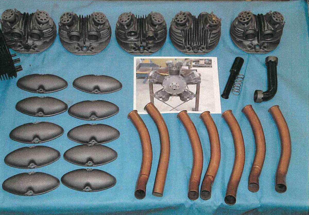
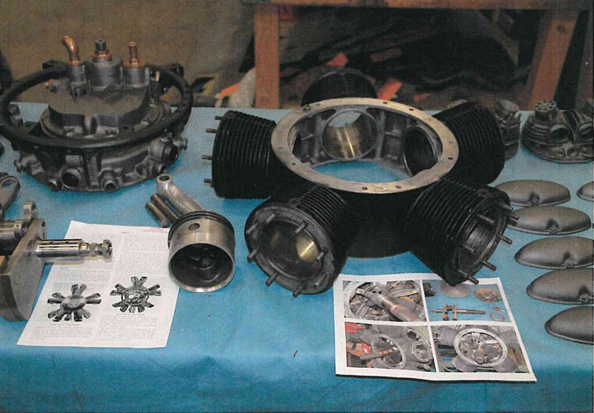
Heat-treated aluminum alloy cylinders and barrel-type crankcase were cast in one piece. Cast iron cylinder liners were pressed into each cylinder and finished-machined. Each cast aluminum alloy hemispherical cylinder head featured shrunk-in aluminum-bronze valve seats and was attached using eight studs and no head gasket. The valves were actuated with rocker arms and push rods driven from a single-row three-lobed cam ring running at one-sixth crankshaft speed.
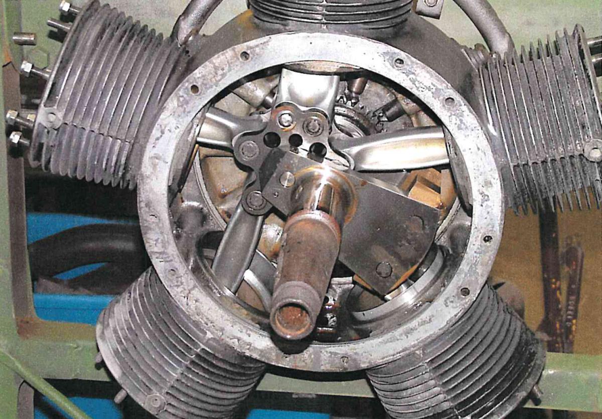
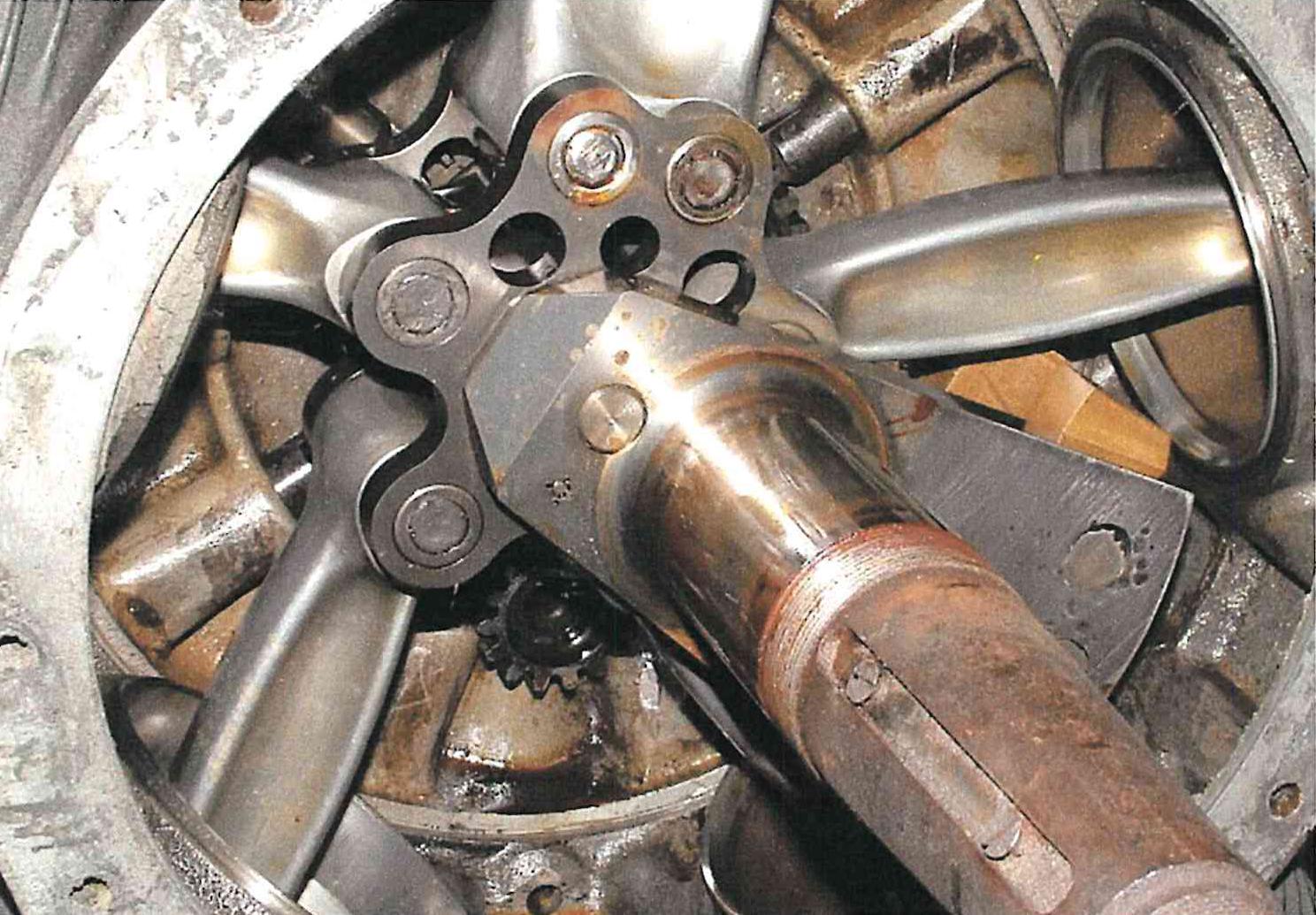
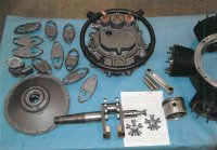
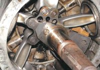
A two-piece crankshaft was joined with a tension bolt through the aft crankcheek, capturing a steel master-rod big-end cluster that was attached to the master rod with two pins and also had provisions for four knuckle pins.Four articulating connecting rods were forged duralumin. The cluster interior was lined with a cadmium-silver crankpin bearing.
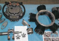
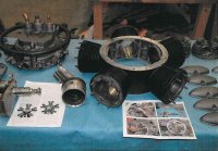
Since the cylinders were not removable, engine assembly differed from other radials. Cast aluminum-alloy pistons with two compression rings and one oil scraper ring were attached to connecting rod small ends using floating nitrided piston pins with aluminum end plugs. The piston assemblies were inserted into their cylinders from the top and the other connecting rod ends were attached to the big-end cluster as described above. Next the fore crankcase cover was assembled with its bearings and slid over the fore crankshaft journal, and the fore crankcase cover into its crankcase counterbore until the mounting flange made contact. The aft crankcase cover was then assembled to include valve timing, ignition timing, accessory drives and oil pump and then installed as a unit onto the aft crankcase and aft crankshaft journal. Offset flats on the aft crankshaft journal and auxiliary shaft allowed the entire aft crankcase assembly to be removed intact without disturbing valve or ignition timing. Ten crankcase through bolts held the crankcase assembly together. The cylinder heads, valve gear, push rod and induction tubes were then installed. Accessories, including one or two Scintilla magnetos and a Stromberg carburetor were added to complete engine assembly.
Although the Angle A-1 was test run and flown in 1939, its development was pursued further during WWII. After WWII, Angle lived in Thomaston, Connecticut and apparently worked for the New Britain Machine Company, to which he assigned the Angle A-1 patents (2,489,946, 2,568,478, 2,576,819 and 2,618,253). This may explain how the New Britain Machine Company wound up with the A-1 prototype, which it ultimately donated to the New England Air Museum.
 |
 |
T.jpg) |
T.jpg) |
T.jpg) |
| Fore |
Aft |
Fore |
Fore |
Aft, Oil Pipes, Tach Drive |
T.jpg) |
T.jpg) |
T.jpg) |
T.jpg) |
T.jpg) |
| Aft, Oil Pipes, Tach Drive |
Cylinder Top |
Cylinder Fore |
Cylinder Aft |
Cylinder Aft |
| Angle A-1 Externals. (Color Images Courtesy of Nick Hurley of the New England Air Museum via John Riend) |
 |
 |
 |
 |
 |
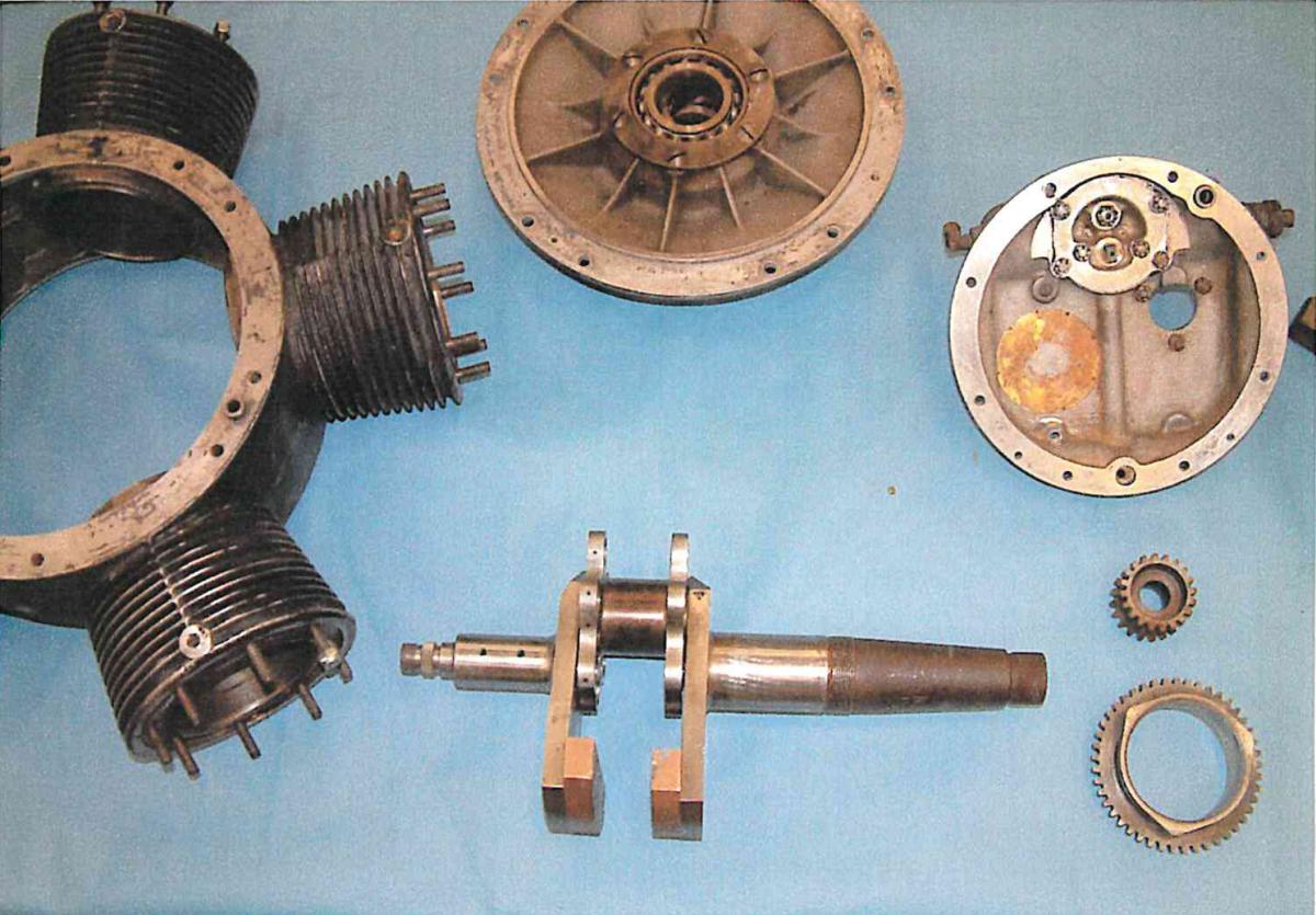
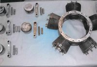
| Pistons, Rods, Pins, Crankcase |
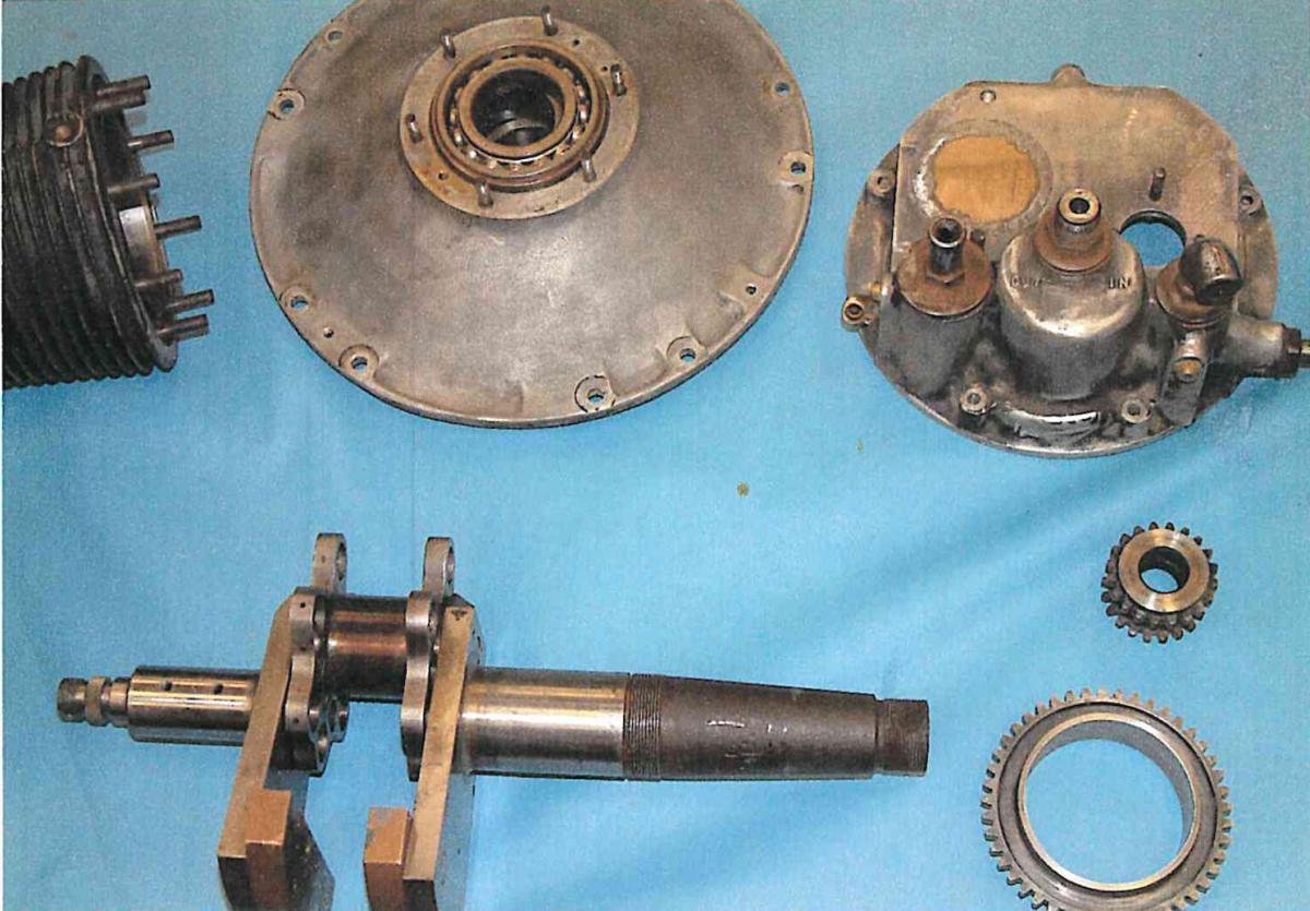
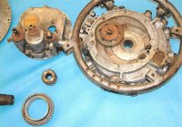
Fore Cover, Aft Cover with Oil Pump, Crankshaft with Cluster, Cam Gear |
Fore Cover, Aft Cover with Oil Pump, Crankshaft with Cluster, Cam Gear |
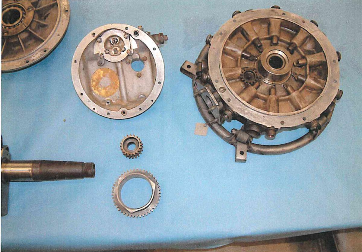
Aft Cover with Oil Pump, Aft Crankcase Cover |
Aft Crankcase Cover with Cam Followers |
 |
 |
 |
 |
 |
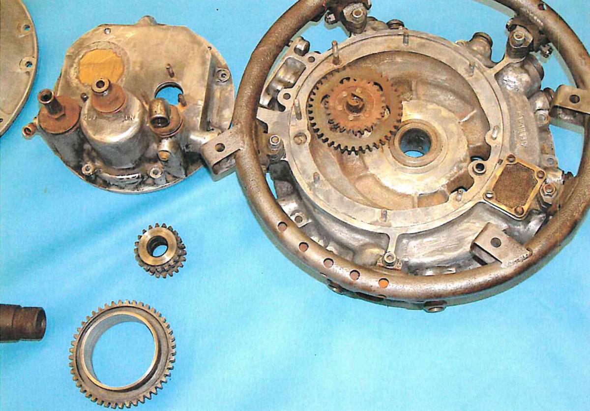
| Aft Cover with Oil Pump, Cam Gear, Aft Crankcase Cover |
Aft Cover Showing Oil In, Oil Out, Oil Pressure Relief Valve, Tach Drive |
Fore Cover, Aft Cover Assembly, Rocker Boxes, Crankshaft with Cluster |
Aft Cover Assembly, Crankshaft with Cluster, Crankcase |
Cylinder Heads, Valve Covers, Exhaust Pipes |
 |
 |
 |
 |
|
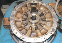
| Crankcase, Aft Cover Assembly |
Pistons, Rods, Crankshaft Installed in Crankcase |
Pistons, Rods, Crankshaft Installed in Crankcase |
Pistons, Rods, Crankshaft Installed in Crankcase |
|
| Angle A-1 Internals. (Images Courtesy of Nick Hurley of the New England Air Museum via John Riend) |
Angle A-1 Details from U.S. Patent 2,618,253
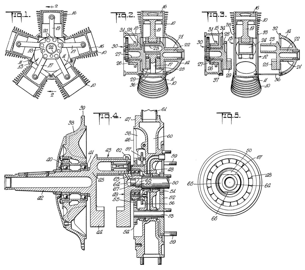 |
Key:
10. Cylinder
11. Crankcase
12. Fore Crankcase Opening
13. Aft Crankcase Opening
14. Fore Crankcase End Plate
15. Aft Crankcase End Plate
16. Piston
17. Articulated Connecting Rod
18. Big-End Cluster
19. Master Connecting Rod
|
20. Master Rod - Cluster Joint
21. Fore Crankshaft Journal
22. Fore Crankshaft
23. Crankpin
24. Big-End Cluster Bore
25. Fore Crankshaft Counterweight
26. Aft Crankshaft Journal
27. Aft Crankshaft
28. Aft Crankcheek
29. Aft Crankshaft Counterweight
30. Reduction Gears
31. Valve Cam Ring
|
32. Fore End Plate Flange
33. Fore Crankcase Counterbore
34. Aft End Plate Flange
35. Aft Crankcase Counterbore
36. Crankcase Through Bolts
37. Tapped Holes
38. Fore End Plate
39. Fore End Plate Flange
40. Bearing
41. Bearing
42. Fore Crankshaft and Propeller Shaft
43. Crankpin
|
44. Counterweight
45. Crankcheek
46. Aft End Plate
47. Aft End Plate Flange
48. Bearing
49. Aft Crankshaft
50. Auxiliary Shaft
51. Pinion
52. Gear
53. Idler Shaft
54. Pinion
55. Gear
|
56. Cam Ring
57. Cam Follower
58. Cam Follower Guide
59. Stud
60. Inlet Manifold System
61. Inlet Passages
62. Clamp Bolt
63. Aft Crankshaft Journal
64. Locating Pin
65. Cylindrical Porting
66. Flat
67. Flat
|


.jpg)
.jpg)
.jpg)
.jpg)
.jpg)
.jpg)
.jpg)
.jpg)