Curtiss D-12 Endurance Test
 |
 |
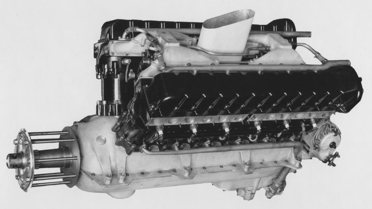
| Fine views of the prototype Curtiss D-12 (Engine No. 1) probably just fresh from the assembly stand. Engine has obviously been polished and cleaned for the photo-shoot. People have often commented on the clean lines and purposeful appearance of the D-12 but experience from WW1 pointed clearly to the necessity of providing reduction gearing for the propellers of high performance engines. The decision of Chief Motor Engineer Arthur Nutt to eliminate the reduction gearing, a feature of the K-12 and C-12, was a retrograde step. | |
N A V Y D E P A R T M E N T BUREAU OF AERONAUTICS REPORT ON Endurance Test of Curtiss D-12 Engine Mfg., No. 1, Navy No. 10098. BY L. D. Gifford, Tester A. Sharpe & A. Saccone, Observers Transcribed by J. Wells, 2012. Editor’s Note: References to pages that were missing from our copy are not included herein. - KDM |
ENDURANCE TEST OF CURTISS D-12 ENGINE.
Mfg. No. 1, Navy No. 10098.
July 19th to Aug. 3rd, 1923.
OBJECT OF TEST.
"This test shall be conducted for the sole purpose of determining the durability of the engine."
(Quoted from Navy Specification No. E-20A).
CONCLUSIONS.
This test and those which preceded it (a total of 275 hours 19 minutes full load and 88 hours 26 minutes part load running) have shown that the wear on the rubbing surfaces of this engine is extremely small. With the exceptions to be noted later, a long life of all parts as installed in the original engine can be counted on, and in the few cases in which performance was not satisfactory, changes have been made on engines being built under contracts No. 56236 and 56992.
DISCUSSION OF RESULTS.
The Endurance Run was conducted on the torque stand at Curtiss Field, Buffalo, N.Y., under supervision of the U.S. Navy Inspector.
The run was made with full rich mixture, with no attempt at best fuel economy. Hence the gasoline consumption was very high. With a leaner carburetor setting during the preliminary run on the dynamometer July 9th, 1923, the fuel consumption was found to be .538 lbs per B.H.P. at rated speed and power.
The purpose of the run was not to determine such characteristics as fuel and oil consumption, heat balance, oil pressure etc., but simply to determine the life of the parts. The run was made at a speed which is the peak of the B.M.E.P. curve to make the test as severe as possible. Most of the parts were from the original engine.
The oil pressure fell off twice during the run. In both cases the screen at the intake to the pressure pump gears was found clogged. A coarse, gritty carbon with particles as large as 1/16 inch cube was found in addition to fine carbon. The screen and its well also contained this grit at the end of the run but the sumps leading to the scavenging gears contained only a small amount of fine grit. Therefore, it is not certain that the coarse carbon was formed in the engine. The oil was screened from the cooler into the tank, and hence one would conclude that the coarse grit was sediment previously contained in the tank and washed over to the oil screen in the engine.
At the end of 15-1/2 hours, leakage from a faulty oil connection outside the engine caused an abnormal oil consumption reading. The leakage was stopped and gave no more trouble.
Difficulty with radiator leakage was experienced due to poor bracing of the radiators. In one case a brace was pulling on the thin metal of the intake passage up the side of the radiator shell. Considerable time was lost changing radiators until a satisfactory arrangement of the bracing was found.
Other troubles experienced were a cracked air chimney (which due to the absence of cowling was subjected to the full force of the slip stream), magneto coupling bolts striking magneto coupling cupped flange, stripped splines on the water pump impeller due to shaft nut improperly secured and working loose, spark plug not firing (4 cases, 2 A-C and 2 B.G.), gasoline pump gasket leaking, and final piston breakage which ended the run. These troubles are described in detail in the Tear Down and Inspection Report.
The failure of the No. L-6 piston which bought an end to the test, and the discovery of eight other pistons with visible cracks in or near the piston bosses showed that the piston C-4053 used during the test was weak in this region. A piston C-4759 much stiffer and stronger in and near the bosses is being installed in the engines now being built.
The test came to an end after 87-1/2 hours, when No. L-6 piston broke thru the bosses breaking the No. L-6 master connecting rod and causing the wreckage shown in photographs 64, 65, 67, 68 & 69.
| AVERAGE DATA | ||||
| 1st 10 hours | Last 10 hours | Total | Average | |
| R. P. M. | 1854 | 1840.5 | 1846 | 1847.25 |
| H. P. Corrected | 368.5 | 360.3 | 363.8 | 364.4 |
| B. H. P. | 356.0 | 347.1 | 351.8 | 351.55 |
| B. M. E. P. (lbs/sq in.) | 132.5 | 130.2 | 131.6 | 131.35 |
| S. F. C.* (lbs per B.H.P. per Hr.) | 0.570 | 0.577 | 0.574 | 0.5735 |
| Hourly Fuel Use (lbs.) | 202.8 | 200.5 | 202 | 201.65 |
| S. O. C.** (lbs per B.H.P./Hr.) | .0132 | .0111 | .0122 | .01215 |
| Hourly Oil Use (lbs.) | 4.69 | 3.84 | 4.29 | 4.265 |
| Heat To Water Jacket (B.T.U./Hr) | 529200 | 457950 | 536300 | 493575 |
| Heat To Water Jacket (B.T.U./min) | 8820 | 7633 | 8938 | 8226.5 |
| Heat To Water Jacket (B.T.U./B.H.P./Hr) | 1486 | 1320 | 1525 | 1403 |
| Heat To Water Jacket (B.T.U./B.H.P./min.) | 24.8 | 22 | 25.4 | 23.4 |
| Temp. Rise - Oil (deg. F.) | 32 | 42 | 37.6 | 37 |
| Temp. Rise-Water | 20 | 16 | 19.2 | 18 |
| Oil Press. (lbs./sq.in.) | 86.9 | 87.4 | 92.8 | 87.15 |
| Manifold Vacuum (Ins.Hg) | 1.74 | 1.20 | 1.60 | 1.47 |
| Carb. Air Temp. | 85.5 | 86.8 | 81.0 | 86.15 |
| Carb. Air Pressure (Ins.Hg) | 29.565 | 29.437 | 29.507 | 29.501 |
| *S.F.C. = Specific Fuel Consumption. **S.O.C. = Specific Oil Consumption. | ||||
| NB: The figures in the fourth column, "Total" are highly suspect, as is the heading, "Total". Figures in the fifth column, "Average" are the sum of columns 2 and 3 divided by 2. -J.SJ.W. |
||||
DESCRIPTION OF ENGINE
General Form.
The Curtiss D-12 engine, manufactured by the Curtiss Aeroplane and Motor Co., Inc. at Buffalo, N.Y., U.S.A. is a development from the Curtiss Model CD-12 engine of the same bore and stroke. It is rated at 350 B.H.P. at 1800 R.P.M.
After exhaustive tests on the Model CD-12 engine it was decided entirely to rebuild the engine to decrease the weight if possible and improve the accessibility, which was already very good. The seven bearing crankshaft was retained as well as the well known use of main bearing caps on the crankcase. The distribution of the main bearing areas was changed to conform with Air Service requirements. This change necessitated the making of entirely new patterns and forging dies for all the main parts of the engine. A careful study was made of each individual part on the engine during this redesigning in order to save weight as well as increase the strength if possible. The details of changes in the various parts of the engine are outlined below. The result of this redesign was an engine weighing 35 lbs. less than the CD-12 while developing 10 to 15 horsepower more at the same speed.
The Curtiss D-12 engine is of the 60 deg. Vee type and it consists of two rows of six cylinders enbloc having a bore of 4-1/2 ins. and a stroke of 6 ins. with a total displacement of 1145 cu. ins.
The compression ratio is 5.3 to 1. The engine is of the aluminum cylinder type with inserted steel sleeves in contact directly with the cooling water. The engine uses two overhead camshafts per cylinder head driven thru bevel gearing and operating four valves per cylinder.
Crankshaft and Bearings.
The crankshaft is of the conventional seven-bearing type, made of low chrome-nickel steel. The crankshaft has been redesigned to take care of the redistribution of the main bearings, the center bearing being 1-3/4 ins. effective length and the balance of the bearings 1-1/2 ins., thereby doing away with the three 1 inch bearings used in the CD-12 engine, making larger bearing surfaces and decreasing manufacturing costs. The same journal and crank pin sizes of 3 ins. and 2-1/2 ins. respectively have been retained. The crank cheeks have been made oval instead of rectangular, increasing the widths 1/4 in. and decreasing the weight at the same time, giving a stronger and lighter shaft. The same type of propeller thrust bearing is used on this engine mounted between the #7 and #8 main bearings namely, a deep-grooved radial annular ball bearing. This bearing takes thrust in either direction and the method of mounting adds greatly to the rigidity of the propeller in flight, very satisfactorily taking care of the gyroscopic forces.
The journal and crank pin bearings are bronze shells lined with babbit. The journal bearings are held in place with brass countersunk head screws and before assembling, the edges project a total of .003 to .005 ins. beyond the bolting faces of the crankcase and bearing caps so that they squeeze together tight when the bolts are drawn up. The crankshafts are lapped to the smallest bearing size and the main bearings are bored out and burnished to a clearance of .002 to .003 ins.
A similar method is used in assembling the crank pin bearings but brass countersunk head rivets to rod and cap are used in place of the screws. The crank pin clearance is .002 to .0025. The crank pin bearings are not burnished.
The wrist pin bushings are of bronze pressed into the forked end of the articulating rod.
The piston pin bushings are of bronze pressed into the rods. The piston pins float in the aluminum of the piston bosses. They are a tight fit when cold but a turning fit when the aluminum expands as the engine grows warm.
The camshaft bearing is in the cast aluminum of the bearings and bearing caps. The pressure comes on the caps.
Pistons.
The same type of piston is used as in the CD-12 engine, being the ribbed head type (shown in the drawing, p 85) which gives a light weight piston of considerable strength. The pistons of the D-12, No. 1 engine were of magnalite and weighed 1.62 lbs. each. At present a 10% copper alloy is used.
The rings are placed lower than in the CD-12 to provide a wider top land and make the rings all the same width. They are .093 ins. wide and .157 ins. thick. The bottom ring acts as an oil scraper ring.
Piston Pin and Wrist Pin.
The piston pin and wrist pin are of high chrome nickel steel, carburized and hardened. The piston pin is held in place by snap rings sprung into grooves in the piston pin bosses. It has no drilled holes. The wrist pin is grooved for a bolt which lies across its face clamping the split boss on the master rod together to hold the wrist pins in place. Two oil tubes pass diagonally thru the wrist pin like the horns of a V. They carry the oil from the crank pin out to the wrist pin bushings.
Cylinders, Valves, Timing.
The same cylinder head construction as used in the CD-12 engine has been retained. Cylinder sleeves of carbon steel hydraulically forged with one end closed are rough machined, heat treated and then machined finished before assembling in the cylinder head with the exception of final grinding of the bore. The threaded portion of the sleeve is approximately 1-1/2 ins. long. Careful machining is done on the sleeves and on the cylinder head to maintain a perfect joint between the aluminum head and the steel sleeve. An integral stud on the end of the closed head of the sleeve passes thru the water jacket, thereby improving the contact between the steel head and the aluminum head. The valve port holes are machined after the sleeve is assembled. Spark plug bushings are also assembled after the sleeve is in place, duralumin bushings being employed instead of the brass formerly used. The aluminum water jacket - which is cast in one piece for six cylinders - is assembled over the lower ends of the six sleeves, the water joint being maintained between the sleeve and jacket by a composition gasket under the flange on the sleeve. The upper joint is made tight with a copper-asbestos gasket. The sleeves fit very snugly in the water jacket at the lower end and thus have ample support to prevent the thin sleeve from going out of round.
There are four valves per cylinder seating in the steel cylinder head with the exhaust on the outside and the intakes on the inside of the Vee. The spark plugs enter from the sides of the combustion chamber, one plug being located between the exhaust valves and the other between the intake valves.
The valve port diameter is 1.531 ins., the valve size being .040 ins. less than in the CD-12 to make the valves removable from the cylinder without removing the valve guides. The valves have a 45 deg seat and are of the tulip form. They are made of Silchrome alloy. The clear gas flow area is 1.84 sq. ins. per valve or 3.68 sq. ins. per pair. The lift is approximately 13/32 ins.
The valve stem clearance in the guides is .0025 to .004 ins. The guides are of cast iron and are finished reamed after assembling with the cylinder head.
The valve springs are helical with two concentric springs per valve. The outer spring is a left hand helix and the inner spring is a right hand helix.
Each pair of intakes and each pair of exhausts is actuated by a single T-shaped cam follower reciprocating in a guide midway between the two valves. The cam wipes across the top lip surface of the follower. This type of follower removes all side thrust from the valve stems. The valve clearance is regulated by adjusting screws clamped in the ends of the cam follower arms. The camshaft bearings are lubricated by oil pressure of approximately 10 lbs./sq.ins. and the cam followers and valve guides are lubricated by splash - the whole mechanism being enclosed under the cylinder head cover.
There are two cam shafts on each cylinder head mounted on six aluminum brackets, the shafts running directly in the aluminum. The brackets are carefully dowelled to the head and are interchangeable, no alignment, reaming, or hand scraping being necessary during manufacture or overhaul. The intake camshaft is driven by the exhaust camshaft thru spur gears at the anti-propeller end. A bevel gear is mounted on the exhaust camshaft in a novel way. The spur gear on the exhaust camshaft is extended beyond the width of its meshing gear and the bevel gear has a Fellows gear shaper spline to fit over the tooth extension. A single large flanged nut holds the bevel gear on the shaft. Owing to the fact that the number of teeth on the spur gear differs from the number of teeth on the bevel gear an adjustment within plus or minus 3 deg. 14 mins on the crankshaft can be obtained by shifting the bevel gear.
The standard timing is:
Intake opens 5 deg B.T.C.
Intake closes 35 deg. A.B.C.
Exhaust opens 55 deg. B.B.C.
Exhaust closes 10 deg. A.T.C.
L.H. magneto breaks (full advance) 28 deg. B.T.C.
R.H. magneto breaks (full advance) 32 deg. B.T.C.
The actual timing before the test was:
Valve Timing Cyl #1 Left Cyl #1 Right
Intake Opens 3-3/4 deg. B.T.C. 8 deg. B.T.C.
Intake Closes 39 deg. A.B.C. 37 deg. A.B.C.
Exhaust Opens 53 deg. B.B.C. 57 deg. B.B.C.
Exhaust Closes 13 deg. A.T.C. 8 deg. A.T.C.
Magneto Breaks (full advance) L.H.S. 29 deg. B.T.C. R.H.S. 31-1/2 deg. B.T.C.
Ignition.
Two, single-spark 12 cylinder Splitdorf magnetos model SS-12 mounted on the gear case and driven by bevel gears meshing with a gear on the vertical drive shaft are used for ignition, feeding two spark plugs per cylinder placed diametrically opposite. The right magneto is wired to the exhaust plugs and the left to the intake plugs. The use of these magnetos saved over six pounds of total weight without a sacrifice of performance or reliability. The magnetos run at 1-1/2 times engine speed.
The magneto timing is adjusted by means of two bolts clamping the magneto coupling ring flange. The former has 32 holes and the latter, 34 giving a timing adjustment of approximately plus or minus 27 mins. of crankshaft rotation.
For the purposes of the test, A-C Aviation spark plugs were used on both intake and exhaust sides in cylinders L-1, L-2, L-3, R-4, R-5, and R-6. BG type 1 x B plugs were used on both intake and exhaust sides in cylinders L-4, L-5, L-6, R-1, R -2, and R-3.
Carburetors.
Two Stromberg model NA-Y5-A carburetors are used with altitude control of the depression type.
The settings used were:
Choke 1-11/16.
Jet 45
Air Bleeder 49
Idling Jet 35
Lubrication.
The conventional Curtiss dry sump lubrication system is used on the engine but the oil tank is not built into the crank case. The lubrication system has been refined to such a degree that a consumption of .015 lbs. per B.H.P. hour may be used as an average figure for continuous flying. Minimum figures of one half of this value have been obtained in block testing. The scavenging pumps which are now entirely separate, eliminate any chance of air entering the system and thereby destroying the pump capacity. These scavenging pumps have been increased 50% in capacity. All plain bearings in the gear case are pressure fed with the exception of the lower vertical shaft which runs in a bath of oil. All other bearings are splash fed by the oil running back from the camshafts which are carefully housed in with an oil tight housing.
The oil enters the engine thru the oil pressure pump screen cover, passes thru the oil pressure pump screen to a blind well in the bottom of the oil pan; thence to the oil pressure pump gears; thence thru the oil pressure pump, thru the crank case tube, drilled holes in the crank case and main bearing oil tube feed tube, to the main bearing oil tube which is bolted to the bottom of the bearing caps; thence thru drilled holes in bearings and caps to the crank shaft journals. Thru drilled holes in journals 2, 4, and 6, the oil enters oil wells in these journals, from which it passes to the crank pins thru steel tubes expanded into holes drilled diagonally thru the crank shaft. Thru drilled holes in the crank pin bearing, connecting rod and wrist pin and diagonal tubes in the wrist pin, the oil is carried to the wrist pin bushings.
Thru drilled holes in journal No. 1 and a tube expanded into the crankshaft, the oil is metered across this journal to a vertical drilled passage in the crank case from which it passes thru a horizontal drilled hole to the vertical drive shaft bushings and thru the crank case to cylinder head oil tubes to the cylinder head; thence to camshaft bearing No. 1, thence to inside the camshafts, thence to camshaft bearings thru drilled holes in the shafts.
The leakage from the camshaft bearings oils the cam followers and valve guides and returns to the crank case thru the cam shaft drive shaft housings and gear case, oiling the camshaft drive shafts, vertical drive shaft and synchronizer gears and ball bearings.
The cylinder walls are lubricated by the oil mist and the bottom piston ring scrapes the oil down into a groove in the piston above the pin. From this groove the oil escapes thru drilled holes in the piston skirt. Two holes carry the oil to the piston pin bearings in the piston. The connecting rod piston pin bushings are lubricated by the oil mist thru holes in the rod and bushing.
A collar with screw threads turned on its outer surface is pressed into the propeller end of the crank shaft and holds back oil leakage at the propeller end of the crank case.
The used oil from the anti-propeller end sump of the oil pan goes to the upper scavenging gears of the oil pump. The oil from the propeller end sump passes thru the scavenging tube and drilled passages to the lower scavenging gears. There are no screens on the scavenging lines.
| Weight of Curtiss 12 Cylinder Model D-12 Aviation Engine No. 1. | |||
| DRY WEIGHT OF BASIC ENGINE | |||
| Parts Name | Weight (lbs.) | Weight (lbs.) | Percent |
| Two cylinder blocks with valves and cam followers | 224.5 | 33.1 | |
| Two sets of camshafts and bearings | 30.5 | 4.5 | |
| Two cylinder head covers | 16.6 | 2.4 | |
| Gear case with vertical shaft, camshaft drive shaft and housing | 32.0 | 4.9 | |
| Crank case with bearing caps and oil tube | 85.5 | 12.6 | |
| Crank shaft with gear and starting clutch | 71.4 | 10.5 | |
| Oil pan with oil pump drive idler gear | 25.5 | 3.7 | |
| One set of pistons complete with rings and pins | 27.0 | 4.0 | |
| One set of connecting rods | 37.5 | 5.5 | |
| Oil pump system | 8.1 | 1.2 | |
| Oil pump | 7.1 | ||
| Oil pressure and oil suction lines | 1.0 | ||
| Water pump system | 12.3 | 1.8 | |
| Water pump | 4.2 | ||
| Water inlet and outlet tubes | 8.1 | ||
| Ignition system | 36.3 | 5.3 | |
| Ignition wires and tubes | 3.7 | ||
| 24 spark plugs | 3.8 | ||
| 2 magnetos (Splitdorf) | 28.8 | ||
| Propeller hub with bolts and flange | 18.1 | 2.7 | |
| Attaching parts (nuts, washers, screws) | 10.2 | 1.5 | |
| Complete assembly of carburetors, intake manifolds and control rods | 42.75 | 6.3 | |
| 2 carburetors (Stromberg NA-5Y) | 17.5 | ||
| One set of manifolds | 17.7 | ||
| Balance | 7.5 | ||
| ======= | ======= | ||
| TOTAL DRY WEIGHT OF BASIC ENGINE | 678.25 | 100 | |
| Gas pump assembly with gear for D-12 triplex | 4.25 | ||
| Gear, gas pump drive shaft housing assembly. | .43 | ||
| Hand starter without crank | 21.5 | ||
| Hand starter crank, 28 ins. Extension | 4.2 | ||
| Water in engine from inlet to outlet | 44.0 | ||
| ======= | |||
| TOTAL WEIGHT OF POWER PLANT | 752.63 | ||
TEAR DOWN AND INSPECTION REPORT.
With the exception of the parts broken and damaged by the breaking of the No. L-6 piston and those hereinafter enumerated, all parts of the engine were found in good condition after the test.
The wear on the bearing surfaces was in practically all cases within the error of measurement; which, taking into consideration the length of time between the micrometer measurements before and after the test, the differences due to taking readings at slightly different points and the human element in screwing up the micrometers and judging tenths of thousandths on the scale, seems to have been about plus or minus .0005 ins. In many cases, this error caused negative wear to be recorded, yet the micrometer readings checked correct and the micrometers checked closely with the standard Gill blocks. In some cases the negative wear readings are due to the form of the inspection sheets which do not always differentiate between readings at one end or another of a pin, so that a reading at one end before the test is compared with a reading at the other end after the test.
Pistons.
The bearing surfaces and heads were in good condition, with no stuck or broken rings and no more than the standard clearance in the ring grooves. The rings showed no evidence of gas leakage. The skirts and ring grooves held very little carbon and the coat on the heads was light, soft and flaky. Much of the carbon flaked off the heads before they could be photographed.
The No. L-6 piston was entirely wreaked, the lower halves of the bosses and the skirt being broken entirely away. The failure of this piston was evidently the cause of the breakage of the No. L-6 connecting rod, which brought an end to the test.
The No. R-6 piston had the skirt partially broken away by the No. R-6 articulating rod, whose lower end was flung back and forth by its toggle action about the wrist pin and crank pin after the master rod broke.
Nos. L-2, L-4 L-5, R-1, R-3, R-4 and R-6 pistons had cracks visible along the tops of the piston pin bosses close to the oil holes which are drilled diagonally thru the bosses.
No. L-3 had a crack visible in the skirt close to one of the piston pin bosses. A No. L-3 piston which was removed from the engine before the test showed a similar crack.
Apparently the explosion pressure caused the bosses to crack in the thin top section weakened by the oil hole. Then the "give" in the cracked bosses subsequently cracked the skirts.
The fillets around the piston pin bosses were smaller than called for on the drawing and in some cases they has apparently been dug out by the tools used in cleaning the core from the casting.
This gouging was particularly noticeable around the bosses of the No. L-6 piston which failed. The sharpness of these gouged out fillets in the boss fragments as shown in photograph 72 has been slightly smoothed out by the photographer in blocking out the background.
Connecting Rods.
Aside from Nos. L-6 and R-6 connecting rods, which were wrecked when the piston failed and cracks in the babbit of the crank pin bearings of rods No. L-4 and L-6, the rods were in excellent condition, with the bearing surfaces smooth and wear scarcely appreciable. The cracks in the babbit in both cases occurred between the points of application of the explosion forces on the master and articulating rods, i.e. between wrist pin and shank of the master rod. There was nothing to show that the No. 6 crank pin had seized when the engine failed. It was in good condition except for the small patch of cracked babbit. The piston failure was clearly the primary cause of the breakdown which ended the test. The condition of the rod bearings is shown in photograph 74. The master rod shank broke near the piston pin boss, as shown in photograph 73.
Crank Shaft.
No appreciable wear was found from the micrometer measurements. The shaft was put on centers and checked with a surface gauge to test whether it had been sprung by the accident. The maximum error in the journals was found to be .0035 ins. and in the crank pins .003 in. This is less than the tolerance for new shafts. No scoring could be found except a small number of fine, characteristic scratches in line with the oil holes. The thrust bearing was in perfect condition.
Lubrication.
No evidence that oil had failed to get to any lubricated surface was found.
In tearing down the engine a small amount of fine carbon was found in the front and rear sumps. The oil screen and its well which are located on the suction side of the pressure gears, contained coarse carbon grit as well as the fine carbon. This coarse grit was also found when cleaning the screen during the test, as noted under "Endurance Run".
The oil pump driven gears showed signs of wear on the bearing surfaces of the teeth from a point of about 1/16 in. from the tip to a point about 1/8 in. from the tip of the tooth. The backlash was .015 in. on the pressure gears, .006 in. on the upper scavenging gears and .008 in. on the lower scavenging gears.
Piston Pin and Wrist Pin.
The piston pins and wrist pins were polished to a bright glaze, with no scoring. No. L-6 piston pin, which was broken in the accident and driven out thru the cylinder, showed great toughness in its fracture (see photographs 68 & 73.)
Cylinders, Valves, Etc.
The cylinders had shown no water leakage and were O.K. except for the breakage which resulted from the piston and connecting rod failure. This is shown in photographs 64, 65, 67 & 68. Nos. L-6 and R-6 sleeves were wrecked and the propeller ends of both water jackets were broken. The heads were uninjured. In attempting to remove the broken piston from the bent liner of cylinder No. 6, it was neglected to remove the valves and they were bent.
The valves in the remaining cylinders were tested for leakage, none showing more than seepage of gasoline. After the valves were removed, a light cut was taken of the seats, piloting in the valve stem guides.
The heads were removed for the first time since the engine was originally assembled and the cylinder head gasket and the packing rings at the bottom of the liners were found to be in perfect condition except for the damage to L-6 and R-6 packing rings due to the connecting rods cutting thru these cylinders.
Serious pitting was found on the intake side of the liners in the right cylinder bank. This pitting occurred on the outside of the sleeves diametrically opposite to the water inlet openings in the jacket. It may possibly have been caused by electrolytic action. A few larger but shallower pits were found on the exhaust side of the left hand cylinder liners. The pitting is shown in photographs 82 & 83.
The camshafts and bearings and the cam followers were found to be in good condition (see photographs 76 & 77).
The experimental felt gasket between the right cylinder head cover and the cylinder head was removed during the test due to slight leakage and was replaced by 1/32 vellum. The shrinkage of the gaskets at the front of both the housing covers is shown in photograph 80. The vellum has a tendency to harden and lose its life sooner than the felt.
Typical cam followers, exhaust valves and intake valves after the test are shown in photograph 77. The bearing surfaces of the valve stems were all in perfect condition. The exhaust valves were burned clean but the intakes were caked with carbon as shown in the view. The seat of the intakes showed a bright ring but the dark color of the exhaust valves extended across the seat.
The tension on all the valve springs was found to be O.K. One inside spring had about 1/3 of a coil broken off. Several outside springs showed wear on their outer surfaces from rubbing on the side of the bored hole in the cylinder head.
Synchronizers.
Photograph 77 shows one of the synchronizers disassembled. Both synchronizers were in perfect condition and evidently gears and bearings had received plenty of oil.
Backlash of Gears.
The gears in the gear case were tested for backlash, and was in no case greater than the allowance for new gears. No backlash between camshaft spur gears could be detected and they turned freely and smoothly.
The backlash of the oil pump gears is noted under "Lubrication".
Magneto Couplings.
The Oldham coupling on the right hand side showed excessive wear. The couplings had seen previous service and no wear measurements had been taken at the start of the test.
The heads of the bolts 6-D-10 which clamp the Thermoid disks had dented the duralumin magneto coupling cupped flanged C-4074 on both magnetos as shown in photograph 81.
These bolts on the right hand side had loosened during the early part of the test and had been replaced with bolts with thinner heads. The thick head bolts have about 1/16 ins. clearance when the engine is stationary and the interference seems to have been caused by vibration and the stretch of the Thermoid disks.
Ignition.
The magneto breaker clearance on both magnetos checked .021 after the test and the points were in good condition.
Water Pump.
An experimental shaft of stainless steel was under test. The splines of the impeller C-4024 stripped during the run on account of the nut not been locked and impeller C-4024, shaft C-4023, nut 124-D5, collar C-4026, washer 34-D-8 and pins 8-D-1 and 13-D-10 were replaced. The pump with these replacements was O.K. at the end of the test.
The Lynite is held from turning on the stainless steel shaft by means of 20 splines of a 32/64 in. pitch, 20 deg. pressure angle, stub-tooth form, 19/32 in. long. The cotter pin hole for the nut on the end of the shaft had been omitted and the shaft proved too hard to drill after heat treatment and too brittle to peen over the nut. The latter was soldered in place but backed off allowing the impeller to rub back and forth on the splines causing the above failure. The damaged parts are shown in photograph 78.
RECOMMENDATIONS.
Pistons.
The magnalite pistons C-4053 made from casting C-4053-C were sand cast with solid bosses. A very thin section at the tops of the bosses and too thin a skirt section around the bosses was probably responsible for the cracks that developed. According to drawing, the section at the top of the boss tapered from a thickness of 1/8 in. to a thickness of 3/16 in. and was weakened by an oil hole drilled diagonally thru it. This is the pressure side of the bearing and it was here that the cracks in the bosses developed, close to the oil hole under the pounding of the explosions. One piston used on the engine during the test and one previously discarded showed cracks in the skirt close to the boss. Here the drawings C-4053 and C-4053-C show a thickness of 1/8 in.
Connecting Rods.
In two cases the babitt showed cracks due to crystallization in the region of maximum bearing pressure. This condition points to the necessity for a better bearing material which will not develop these local cracks. The wear was scarcely measurable and the crystallization was the only trouble experienced. The Curtiss Co. is about to conduct tests on several promising bearing materials to be used without babbit.
Lubrication.
A larger oil screen with provision for lifting when the oil is cold and stiff at starting would be desirable.
Cylinder Head Cover Gaskets.
A gasket material with less tendency to shrink than felt and less tendency to grow hard and lifeless than velum would be desirable in future engines. One more cap screw at the anti-propeller end and a wider flange on the cylinder head cover at this point are being used in a later engine to obviate the possibility of leakage due to gasket shrinkage at this point.
Magneto Couplings.
Thin head bolts should be used to clamp the Thermoid disks to prevent interference with the cupped disks. This change has been made. A study should be made with a view towards diminishing wear on the Oldham couplings.
Water Pump Impeller.
The water pump impellers have given satisfactory service except in the case where an improperly secured retaining nut worked loose. Two different types of duralumin impeller are, however, under test.
TEST APPARATUS AND METHOD.
Installation.
The engine was mounted on a torque stand on the west side of one of the hangars under a shed open at front and rear. The propeller was to the east, next to the hangar.
The instrument panel was in a small room under the roof of the test shed to the north of the engine. Its general arrangement is shown in photograph 66.
The engine bearers were mounted on trunnions and transmitted the torque thru a lever and rocker arm to a spring scale in the test house. The torque load thus read was extremely inaccurate due to difficulty in reading the rapidly vibrating scale pointer, constantly varying tension of the scale spring and stiffness in the piping connections to the engine.
Three radiators were mounted on a stationary timber at the anti-propeller end of the engine and fed from an elevated tank which, with engine, pump and radiators, formed a closed circulating system.
An oil cooler was mounted on the torque stand.
A tank in the test house could be used as a reserve cooler if necessary. The oil overflowed from this tank to a tank resting on a scale. From here it returned to the pump. The tank on the scale was weighed every thirty minutes to obtain the oil consumption. This tank was open at the top and occasionally the system was refilled at this point, thus losing a weight reading. Gulf Refining Co. grade 90-95 oil was used.
The gasoline was pumped with a Bowzer pump from the barrels over to a drum resting on the scale. From this drum it was delivered to the engine by the gasoline pump mounted on the engine. The drum was weighed every thirty minutes to obtain the gasoline consumption. In general, it was refilled after two readings, losing one weight reading. Domestic aviation gasoline conforming to specifications was used.
Calculations.
The method of obtaining the corrected horsepower was as follows. The engine was run at full throttle on the dynamometer July 9th, 1923 at speeds ranging from 1600 to 2010 R.P.M. and a curve was plotted of horsepower corrected to 60 deg. F. and 29.92 in. Hg. (see curve p 40). Thru the horsepower at 1850 R.P.M., a theoretical propeller load horsepower curve was plotted, assuming that the propeller load horsepower varies as the cube of the rotative speed. During the test the R.P.M. was found by counter readings at exactly thirty minute intervals and the corresponding corrected horsepower was taken from the propeller load curve. The brake horsepower was computed from the corrected horsepower at 60 deg. F. and 29.92 ins. Hg.
The brake mean effective pressure, specific fuel and oil consumption and heat to water jackets per B.H.P.hr were computed on a basis of brake horsepower.
The water flow and manifold vacuum were read by two mercury "U" tubes, as shown in photograph 66.
The water flow was measured by a one inch Venturi meter C-5055, Bureau of Aeronautics Plan No. Air 837.
The water pressure at the inlet to the pump was read by a water column located too high to show on the photo of the instrument board.
The air pressure at the inlet to the carburetor was read by an aneroid barometer located in the still air outside the test house. The aneroid was checked for several days in comparison with a mercury column barometer and no error was found large enough to cause an appreciable change in the computed B.H.P.
The air temperature at the inlet to the carburetor and the humidity were read from a dry and wet bulb thermometer mounted on the torque stand and therefore were probably affected by both the slipstream and the afternoon sunshine.
The air vacuum at the inlet to the carburetor was read by the height of a column above a water level 6-1/2 ft. below the inlet to carburetor, the resulting error due to a column of air of this height being negligible.
The water pressure at the outlet of cylinders was read from a gage 9 ins. below the water outlets, the resulting error being about 0.3 lb/sq. in. The water outlets were 113 ins. below the top of the reserve water tank and hence under a considerable water head. The heights of various points in the installation are shown in the diagram on p 39.
The fitting that held the oil inlet thermometer did not let it enter the standard depth into the oil. Hence the readings are low and the recorded temperature is high.
Send mail to
![]() with questions or comments about this web site.
with questions or comments about this web site.
![]()