Crankshaft Counterweight Capers at Allison
by Jerry Wells
Published by the Rolls-Royce Heritage Trust in 2020. Published by the AEHS 4 Jan 2021
 |
 |
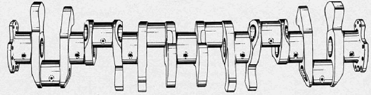
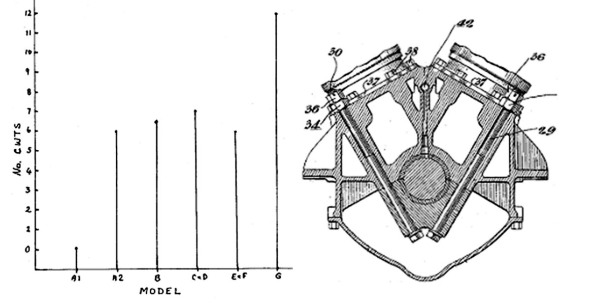
| Fig. 1. A 12-counterweight crank in its transport crate with the claw-shaped counterweights casting distinctive shadows on the box walls. |
Fig. 2. Drawing of the 12- counterweight crankshaft. Note that even the integral end flanges have cut-outs in them to allow milling tools access to the crankpins. |
 |
 |
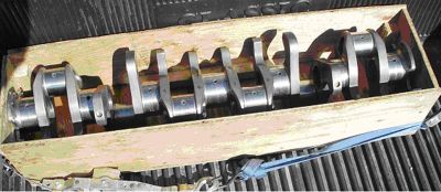
| Fig. 3. Allison 12 counterweight crankshaft on a lathe prior to machining. |
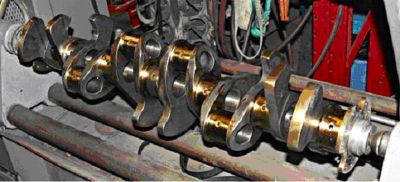
Fig. 4. Drawing to show the location and shapes of counterweights on the #44510 crankshaft. There is an inconsistency here, in that the middle two crankpins are shown above the centre-line in the top drawing but in the crank cheek pictures they (#5 & 8 and #6 & 7) are where they should be, below the line. |
 |
 |
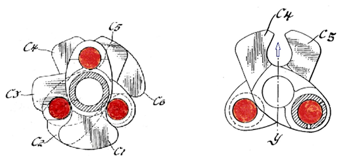
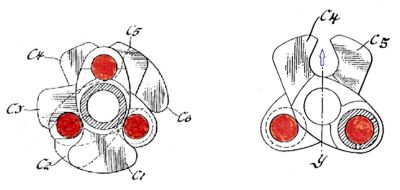
Fig. 5 (left). This is an end view of the 12-counterweight crankshaft front half. It shows that none of the six counterweights (C1 to C6) obstructs the passage of boring or milling drills to any of the three crankpin interiors (orange circles).
Fig. 6 (right). This drawing shows how the resultant of two skewed counterweights helps to balance two opposite crankpins. |
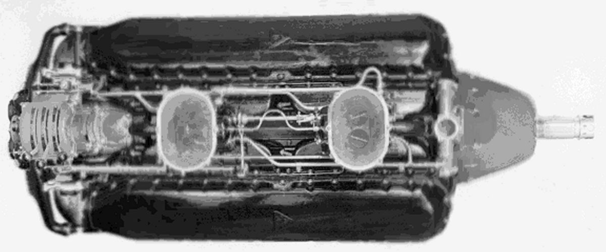
Fig. 7. Top view of the B-model V-1710 showing the distinctive downdraft carburettors and the control levers at the engine's rear. |
 |
 |
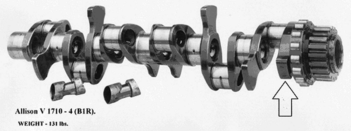
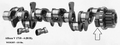
| Fig. 8. V-1710 B-model crankshaft showing the asymmetric extra counterweight at the front of the shaft. Weight given probably includes the roller bearing and the pinion. |
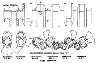
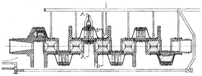
Fig. 9. Longitudinal section of the C-model crankshaft showing the massive strengthening of the front crankpin and the addition of a seventh balance weight, as well. |
 |
 |
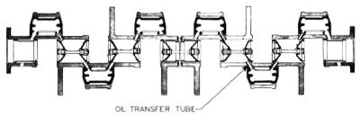
| Fig. 10. Crankshaft of the later V-1710 F-model showing the much tidier arrangement of both the shaft and the counterweights. |
Fig. 11 (left). Changes in number of counterweights on the V-1710 crankshaft.
Fig. 12 (right). Transverse section of a Packard A-2500 aero-engine crankcase designed in the 1920s. It shows how the crankcase side walls have been extended down by a significant amount to strengthen the main bearing support. |
The most sophisticated crankshaft design used in the Allison V-1710 engine was the 12-counterweight version introduced in the later years of WWII.
As can be seen in Figs. 1, 2, and 3, it is the claw-shaped counterweights that give this particular crankshaft its distinctive appearance.
According to the designers of this component, (Charles J. McDowall and Dimitrius Gerdan), eight of the twelve counterweights were claw-shaped, 1) to allow the counterweight on one crankpin to contribute to the balancing of the adjacent crankpin, as well as its own and, 2) to provide clearance for the horizontal drills and milling tools required to form and finish the crankpin interior oil spaces during manufacture. (see Figs. 5 and 6)
Using twelve relatively short balance weights enabled the counterweights to be formed integrally with the rest of the shaft resulting in a stronger finished component.
However the road to getting the right number, shape and distribution of the counterweights was long and rough!
From 0 Counterweights to 12
The prototype V-1710 engine first ran in August, 1931. Its crankshaft had no counterweights at all and after 60 hours testing, the crankshaft broke at the front crank cheek.
Even at this very early stage of the V-1710’s development, “the writing was on the wall” – 1) the crankshaft on this engine had a torsional vibration problem and 2) it was located at the front of the shaft.
The second V-1710, the A2 with its distinctive streamlined long nose, had six counterweights on the shaft and in this form, successfully completed a 50 hour test at 800 hp.
Allison’s next three engines were manufactured under a Navy contract that required power plants for airships. As can be seen in Figure 8, the crankshaft had six symmetrical counterweights but in addition, there was a short, thick weight on the No 1 crank cheek. As these airship engines were relatively unstressed, problems due to torsional vibration of the crankshaft did not occur.
The C-model, developed from the long-nose A2, was for use in monoplane fighter aircraft and therefore had to pass a stringent 150 hour test. At this stage the engine had only a friction damper attached to the reduction gear to smooth out the troublesome vibrations and the fact that the crankshafts kept breaking, meant it wasn’t up to the job.
Fortunately, some work had been done on vibration control in radial engines at about this time and the Dynamic Pendulum Damper has proved to be very successful. It was not until Allison attached this type of vibration controller to the back of the early C-model crankshaft that the 150 hour test required for type qualification was passed. None the less, the untidy looking 7- counterweight crankshaft with its associated reinforcements had to be used for satisfactory reliability. Trying to prevent the crankshaft disintegrating at the #6 (front) crankpin required some drastic measures. Careful examination of the crankshaft front in Figure 9 shows, 1) the forward-most crank cheek (#12) was strengthened, a) by adding more metal to it and, b) by only drilling part way through the #6 crank pin during the creation of the crank pin internal oil space, i.e. the #12 crank cheek was not penetrated.
2) The front crank pin was strengthened by reducing the diameter of the #6 crank pin oil-space by about 3/8” compared to #’s 2-5.
3) A full sized counterweight was added as an extension of the forward-most crank cheek (#12), thus matching the “normal” one already on the #11 crank cheek, i.e., both crank cheeks of the forward-most crank throw now had counterweights. This whole crankshaft looks like an exercise in hasty redesign!
By the time the V-1710 F-model (with its compact spur-type reduction gear at the front) was ready for service, pendulum dampers and hydraulic devices exerted enough vibration control over the crankshaft to allow reversion to a six counterweight crankshaft of more aesthetic design. (see Fig.10)
So, at this stage, the counterweight numbers had gone from 0 to 6 to 6+ to 7 and back to 6! The final jump to 12 was hardly worth it. Yes, there was some reduction in various stresses but only at high speed and the 12 counterweight shaft was no light weight at 144 lb. This was about 20 lb heavier than 6 counterweight crankshafts.
Allison Analysis
So what were the reasons for the torsional vibration problems experienced by the Allison V-12? There were no vibration dampers on the Merlin or the DB601 or the Junkers 211, so why the V-1710? Most likely cause was the design of the engine’s crankcase which was similar to the Liberty’s in that it consisted of two approximately equal shells joined together along the crankshaft centre-line thus providing a plane of weakness at the least desirable spot. If Norm Gilman had taken the time to study engines such as the Napier Lion or even the post-Liberty Packard types e.g. the A-1500/2500 V-12s, he would have quickly realised that the best way to stabilize the crankshaft was to deep-skirt the upper crankcase shell thus surrounding the crankshaft and its bearings with a solid casting of metal. (see Fig. 12)
Cross-bolting of the main bearing caps either through the sump or the upper crankcase had also been developed during the pre-V-1710 time frame – another invention which had obviously escaped Gilman’s notice.
The other point is that the Allison designers seemed to have no appreciation that different parts of a crankshaft have different needs regarding balancing. By and large, if they added a balance weight to one crankpin, then every other crankpin, seemingly, had to have a similar lump! The Merlin crankshaft had eight counterweights – two big ones at each end, two big ones on either side of the centre main bearing and four smaller ones elsewhere. Horses for courses! Twelve counterweights on a V-12 crankshaft was probably, “over-kill”.
The Allison crankshaft was a clear case of development triumphing over design!