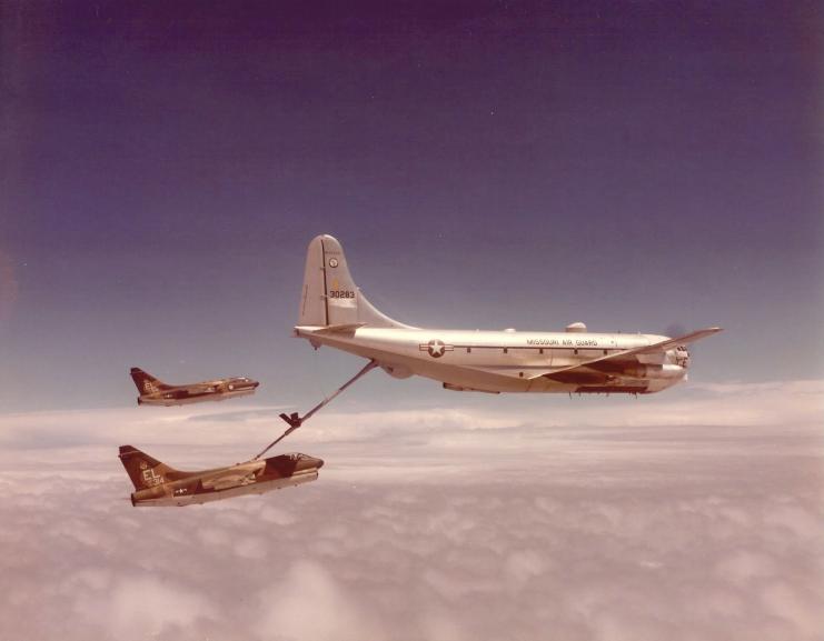
KC-97 Refuels an A-7
(Wikipedia)
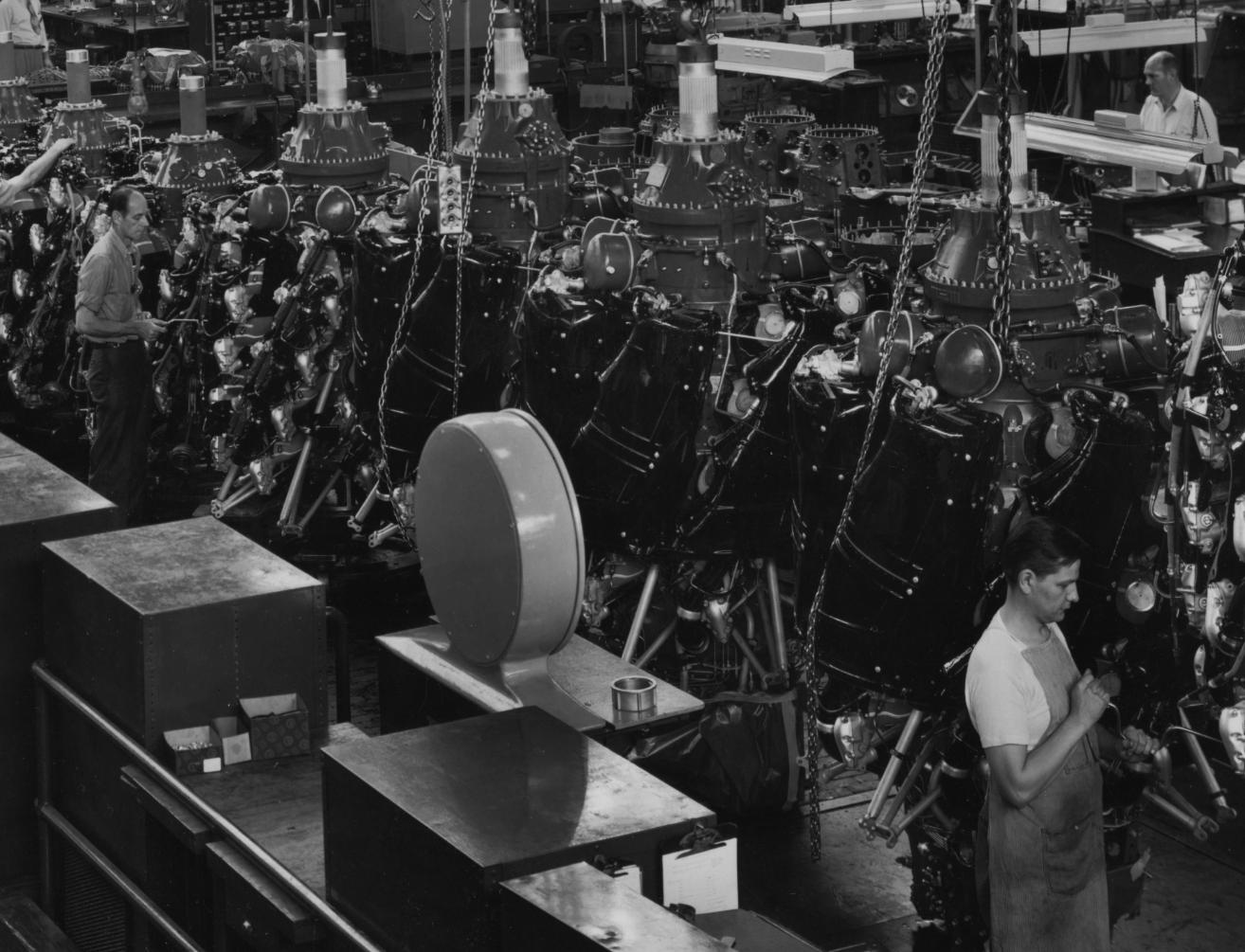
P&W R-4360 Production
(National Archives)
Operating the Pratt & Whitney R-4360-59B
by Gerard L. Blake
1 Aug 2008; Revised 6 Nov 2022
KC-97 Refuels an A-7 (Wikipedia) |
The following narrative reflects some personal experiences gleaned from my somewhat fading memory and appropriate technical data of more than nine years (1961-1970) of operating R-4360-59B engines while I was employed as an Instructor Flight Engineer on Boeing C-97F/G aircraft. | P&W R-4360 Production (National Archives) |
The Pratt & Whitney R-4360-59B is a fixed radial engine of 28 cylinders arranged in 4 rows of 7 cylinders in each row.
Of all the models of the R-4360 engines produced by Pratt & Whitney and the Ford Motor Company, the dash 59B was the most numerous with 4,260 engines manufactured in the 1950s. The -59B was installed primarily on United States Air Force/Air National Guard KC-97 F-G-L and C-97F-G (converted KC-97F-G) aircraft. The information in this article is specific to operations of the C-97G airplane.
All are under conditions as defined by the International Standard Atmosphere (ISA).
Maximum Take-Off Power Wet, using Anti Detonant Injection (ADI) fluid: Five minutes maximum duration, 3,500 bhp @ 247 psi indicated torque pressure, 60" Manifold Absolute Pressure (MAP), 2,700 rpm @ 20° spark advance. With a fuel flow of about 2,500 lb/hr per engine, cylinder Brake Mean Effective Pressure (BMEP) was approximately 235.3 psi.
Maximum Take-Off Power Dry, without ADI: Normally five minutes maximum duration, 3,250 BHP @ 230 psi indicated torque pressure, 60" MAP, 2,700 rpm @ 20° spark advance. With a fuel flow of about 3,000 lb/hr per engine, cylinder BMEP was approximately 218.4 psi.
Military Power: Same as Maximum Take-Off Power, Dry, with a 30 minute maximum duration.
Maximum Except Take-Off Power (METO): 198 psi indicated torque pressure, 50.5" MAP, 2,550 rpm @ 20° spark advance.
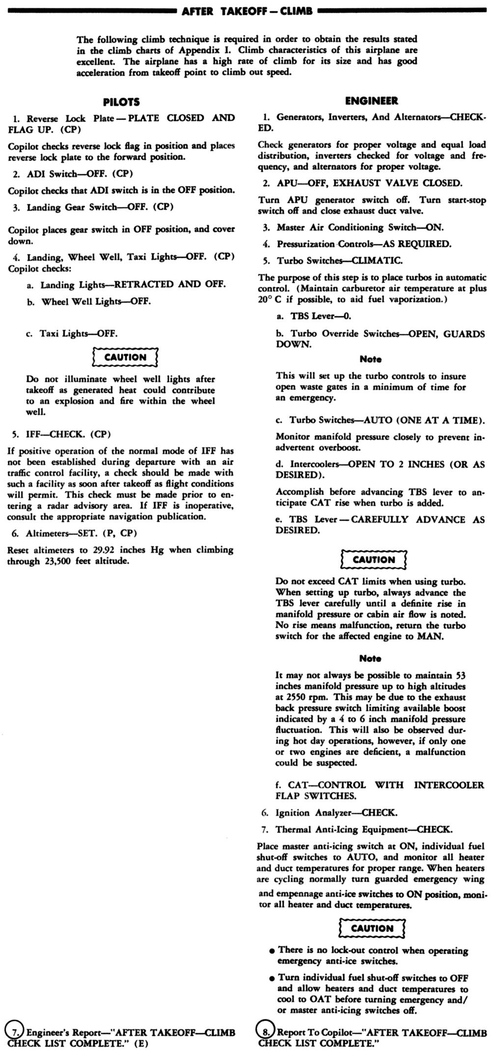
Climb Power: 187 psi indicated torque pressure, 45" MAP, 2,350 rpm @ 20° spark advance.
Propeller Reduction:A single stage planetary system with a 0.375:1 gear ratio and integral torque meter.
Compression Ratio: 6.7:1
Internal Supercharger: Single stage, single speed with a ratio of 6.375:1
Turbo supercharger: General Electric BH-4 with intercooler.
Carburetor: One Bendix PR-100B3-4 pressure carburetor with integral ADI derichment valve.
Ignition System: 4 Scintilla S14RN-15 low tension magnetos mounted on the propeller reduction gear case, 56 Transformer Coils (2 mounted on the top of each cylinder) and 56 fine-wire spark plugs. The magneto gear drive mechanism permitted the Flight Engineer to select either 20° or 30° spark advance magneto-to-engine timing. The 30° selection was limited to cruise power settings only.
Propellers: Four solid aluminum bladed Hamilton Standard 34G60 constant speed, full feathering, reversing, with pitch lock over speed protection. The combination of the R-4360-59B and the Hamilton Standard 34G60 propeller resulted in an unfortunate operational limitation. For all ground operations a restricted rpm range of 1,250 to 1,650 and 2,100 to 2,650 prevented continuous operation within these ranges. In flight continuous operation was not permitted between 2,100 and 2,350 rpm.
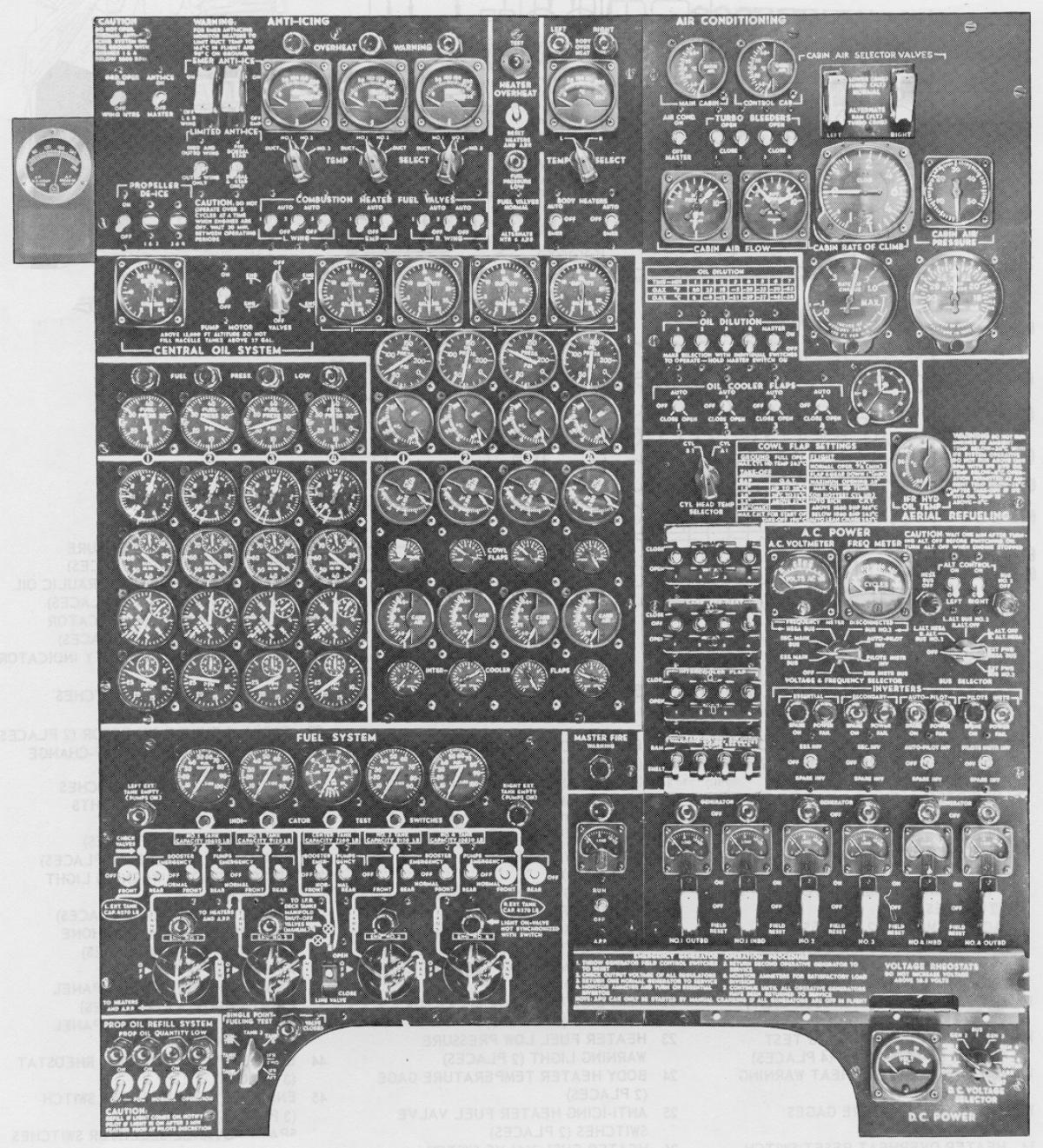
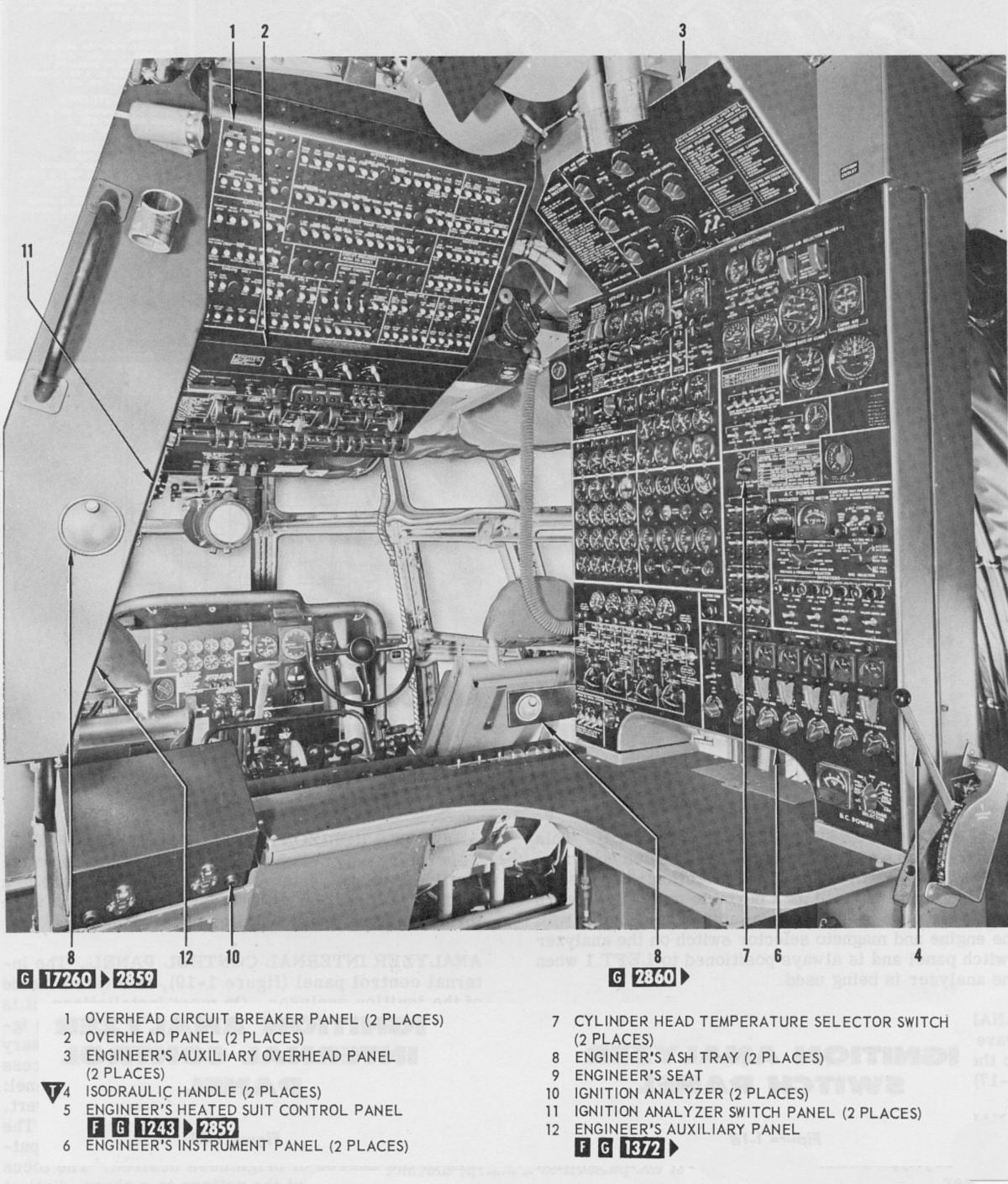 KC-97 Flight Engineers Station |
KC-97 Flight Engineer's Station Detail |
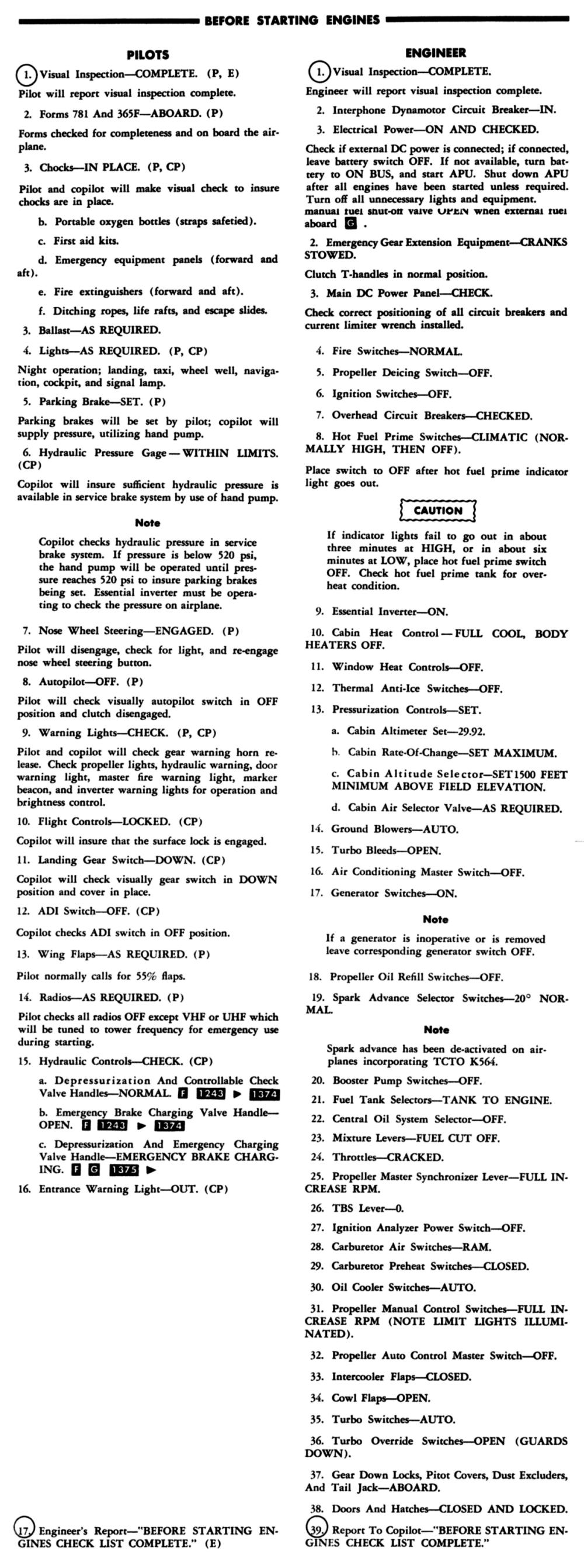
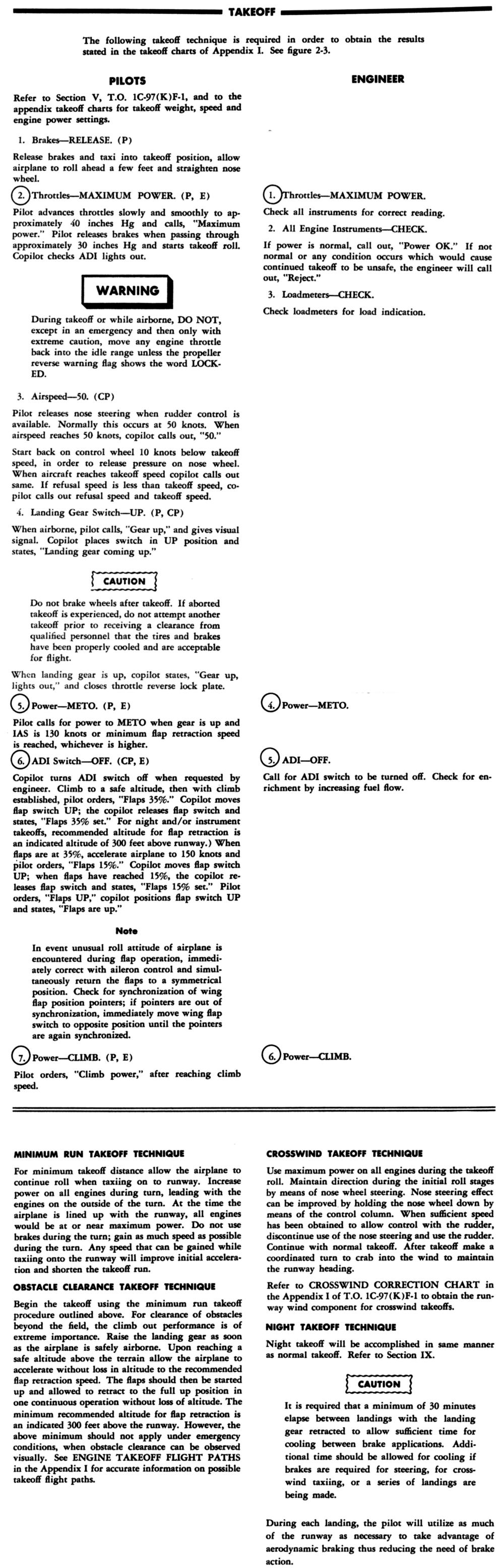
| Before Starting Engines | Take Off | Descent |
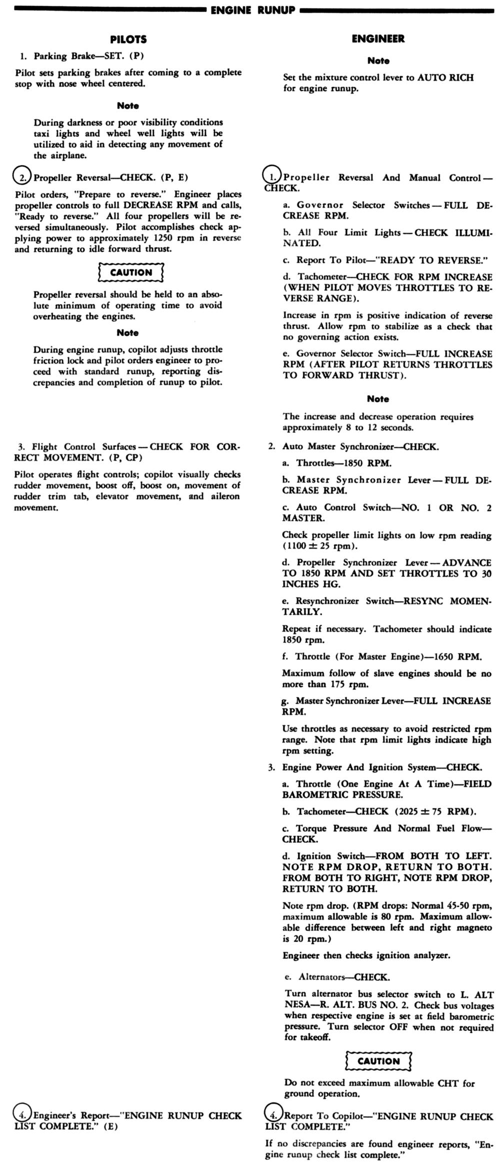
| Engine Run Up | After Take Off | Landing |
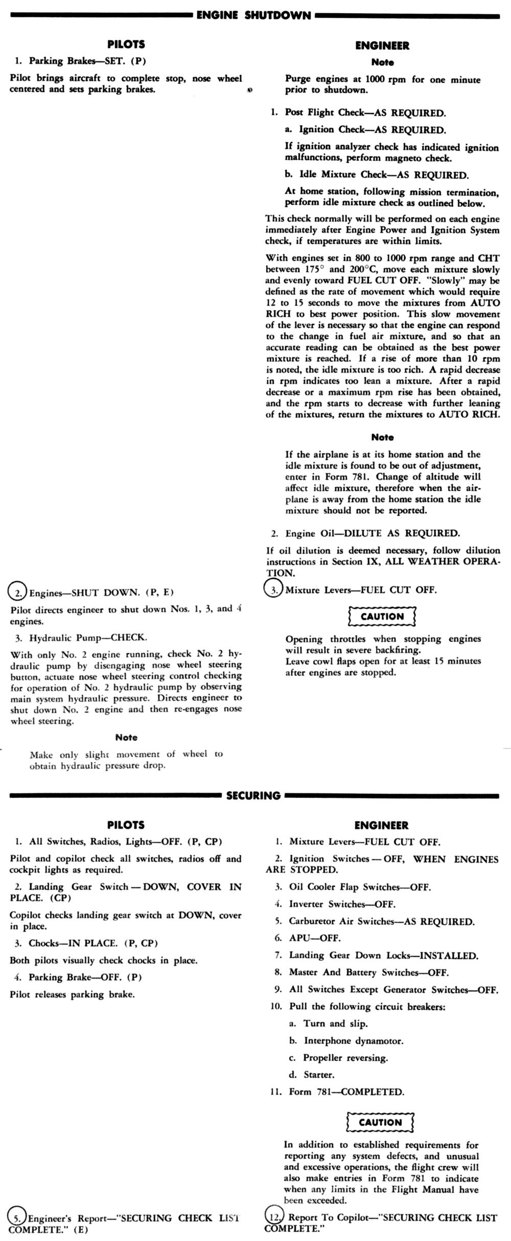
| Before Take Off | Climb | Engine Shutdown |
On the C-97G the engine start sequence was #3, #4, #2, #1. Manipulating the start, prime and ignition boost push button switches with the left hand and the mixture control and throttle levers with the right required a little manual dexterity on the part of the Flight Engineer. After completing the "Before Starting Engines" checklist, the engineer reached up and slightly to his left and rotated the start selector switch to #3 engine and depressed the starter button with the middle finger of his left hand. Upon engine rotation the copilot began counting the number of blades on #3 propeller as they rotated past a fixed reference point. This was to check for any cylinder hydraulic locks and to lubricate the engine and propeller reduction gear bearings. When the blade count reached 20, the Flight Engineer rotated the magneto switch to the "Both" position, depressed the ignition boost and prime switches with the remaining two middle finger tips of the left hand while keeping the starter button depressed with the middle finger. When the engine fired the throttle was slowly advanced with the right hand, the start and ignition boost buttons were released and the engine was stabilized at 1,000 rpm with continuous prime and throttle position. At this point the mixture control was advanced from the idle cut off to the Auto Rich position. When a 100 rpm drop was observed, due to an overly rich mixture indicating that the carburetor was metering, the prime switch was released. Forgetting to turn the magneto switch on, prematurely releasing the starter button, and positioning a throttle to far open resulting in a dreaded backfire were things to be avoided.
Fouled spark plugs due to extended ground running were avoided by manually leaning all engines to at least 20 to 40 rpm decrease. I used 50 to100 rpm, lean of best power for all ground operations and while we were awaiting ATC clearance. For extended periods the engines were run up to field barometric pressure every 10 minutes for 1 minute. The turbo superchargers were also pre-oiled by closing the waste gates for 1 minute at 1,000 engine rpm. An oil temperature minimum of 40°C was required before 1,200 engine rpm could be exceeded.
All engines were exercised from forward thrust to reverse thrust and back to forward thrust. With the propeller controls in full increase position 1,850 rpm was set on all four engines and the alternators, generators, propeller synchronizing system checked. The propellers were exercised from full increase to full decrease and back to full increase position. Each engine was then evaluated independently by setting the throttle to the previously recorded field barometric pressure. The indicated rpm was verified to be 2,025 rpm plus or minus 75 rpm, all other engine instruments were checked to be within their normal operating ranges and the left and right magnetos checked. The throttle was then retarded to 1,000 rpm, the engine leaned to 20 to 40 rpm lean of best power and succeeding engines evaluated.
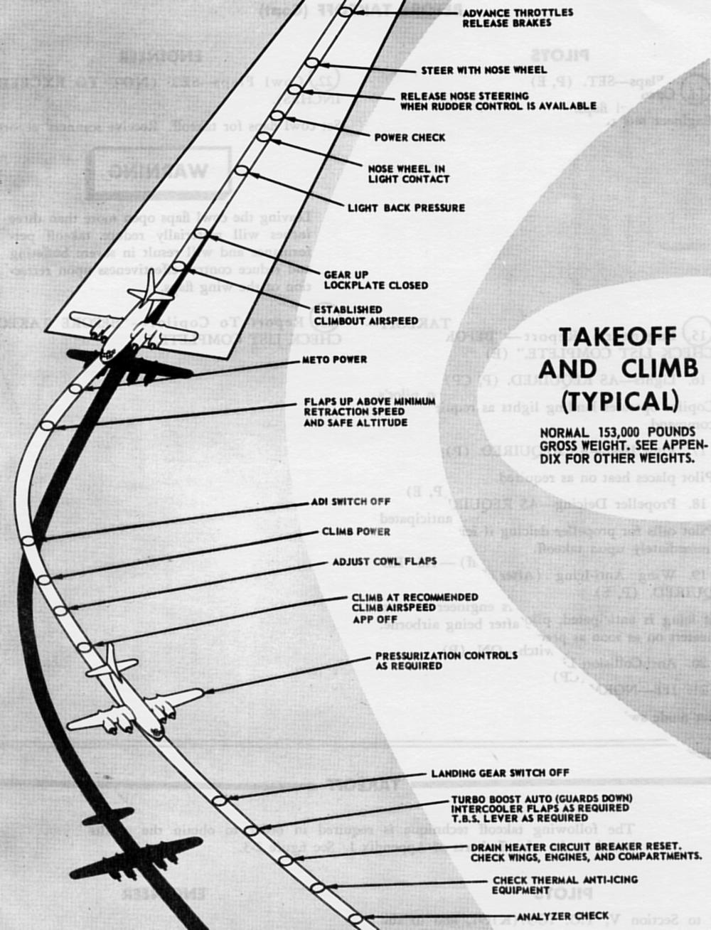 Typical Take Off Note how busy the Flight Engineer is! |
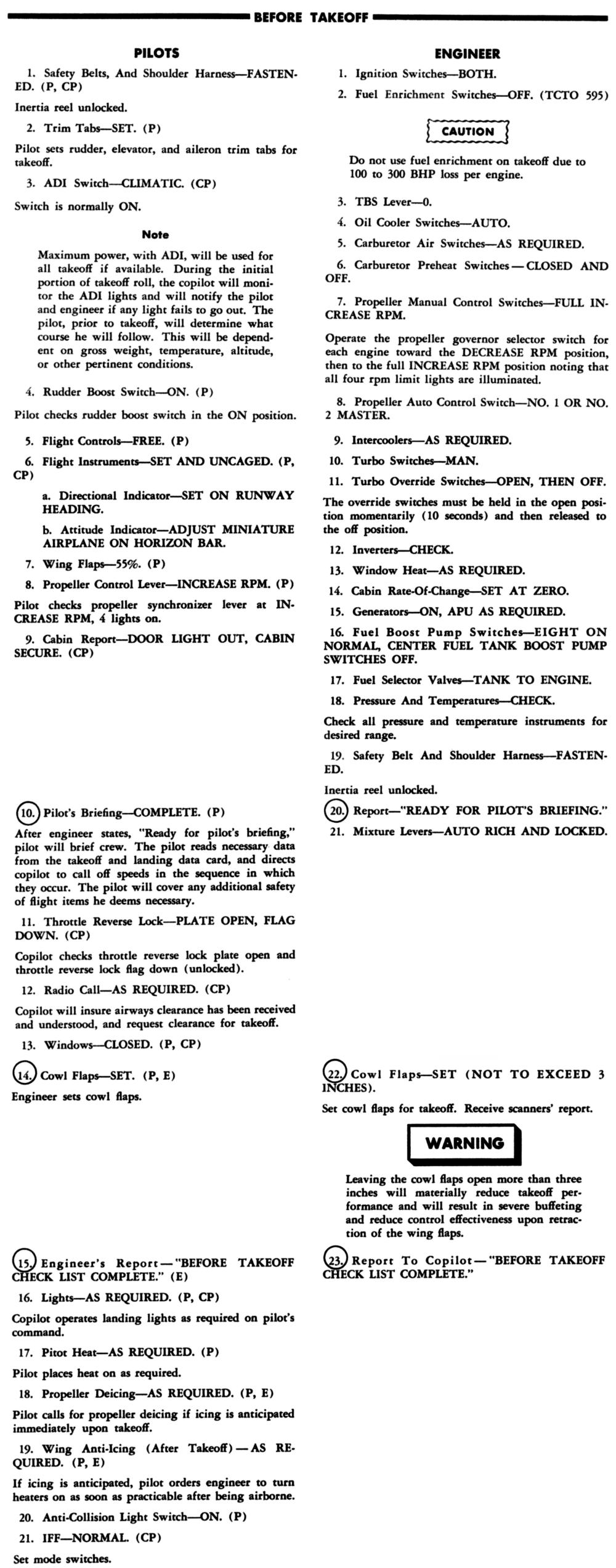
With the Before Take-Off checklist completed, the Line Up check list was normally completed while taxing into take off position on the runway. Once in position the pilot released the brakes, advanced the throttles and called for max power. In addition to preflighting the aircraft the Flight Engineer was responsible for preparing a Take-Off and Landing Data Card (TOLD Card) for all take-offs and landings. The card listed predicted engine performance and critical speeds obtained from charted information in the aircraft performance handbook. Since all aircraft and engine specifications were based on recognized International Standard Atmospheric (ISA) conditions, if the prevailing atmospheric density was below standard the engine was going to be "Torque Limited" or if the conditions were above standard the engine would be "Manifold Pressure Limited. With the call for "Max Power" the engineer continued to advance the throttles. At 45" MAP manifold pressure switches in each engine power pack closed which completed the ADI circuitry and opened the ADI shut off valves. With ADI flowing through regulators the derichment valves at each carburetor reduced fuel flow from 3,000 lb/hr to 2,500 lb/hr. This reduction in fuel flow verified that the ADI system was functioning and that the engine was producing up to 3,500 bhp @ 247 psi indicated torque pressure. Torque pressure was the limiting engine parameter at density conditions below standard. If conditions were above standard density conditions, the engineer would set the maximum of 60" MAP and take what ever power the engine could produce as indicated by respective engine torquemeters and predicted by the performance charts. Engine performance below predicted values was reason to abort the take-off. A dry (no ADI) takeoff procedure was the same except the engine was limited to 3,250 bhp @ 230 psi indicated torque pressure and/or 60" MAP. When all take-off obstacles were cleared, the pilot called for and the engineer set METO Power at 198 psi indicated torque pressure and/or 50.5" MAP and the ADI system was disarmed. If weather conditions required warming the carburetor air temperature the turbo superchargers were brought on stream at this time since they were the only source of carburetor heat. Normally turbo supercharger use began after climb power, 187 psi indicated torque pressure and/or 45" MAP, was set.
|
Normal cruising used manual leaning and manual control of spark advance when spark advance was enabled.
Factors that affected efficient normal cruise operations included:
1. The weight of the aircraft at the top of climb.
2. The density of the atmosphere.
These two factors determined the required engine power to produce a true air speed at a minimal wing angle of attack as predicted by the aircraft performance cruise charts. Applying wind speed and direction, the range of the aircraft was determined.
3. Engine Time Between Overhauls (TBO), or how fast do you want to wear the engine out?
By the time that I was involved in the intimate operations of the R-4360 engine a lot of experience had been accumulated that pretty much dictated the procedures best suited to both efficiently operate the engine and extend the TBO. In a nutshell this amounted to not using anymore than 150 psi BMEP for cruise power settings. The unfortunate in-flight engine rpm restricted range of 2,100 to 2,350 had to be considered also. The compromise that resulted from these limitations dictated that if manual leaning with spark advance were to be used, 1,735 bhp (158 psi indicated torque pressure, 2,100 rpm, which produced 150 psi BMEP) was the maximum cruise power setting to be used. So that’s how we operated the engine. We used the appropriate (and very accurate) cruise altitude charts in the performance flight manual to chose a power setting for a given aircraft weight, corrected for density altitude and always used 158 psi indicated torque pressure and the necessary rpm to provide a specific bhp that resulted in the appropriate indicated airspeed to develop the range for the mission.
4. Engine temperatures. The flight manual established operating temperature parameters that were strictly adhered to. Even though the maximum cylinder head temperature in cruise was 243°C we limited it to 230°C as recommended in order to prolong cylinder life. Carburetor air temperature was maintained at 20°C by varying the airflow across the intercooler with an exit door.
5. Manual leaning and the use of spark advance enhanced the range capabilities of the aircraft because of improved specific fuel consumption. By carefully maintaining recommended cylinder head and carburetor air temperatures with stable turbo supercharger operations, charge density could be held at an efficient value. Since flame speed is typically reduced at leaner fuel air ratios below approximately 0.077, advancing the magneto/engine timing from 20° to 30° spark advance maintained peak cylinder pressure at the most effective 15° after top dead center position. This combination, manual leaning and spark advance also lowered exhaust gas temperatures, which favored longer valve exhaust, system and turbo supercharger life. Last but not least cowl flap openings could be reduced because the engine ran cooler.
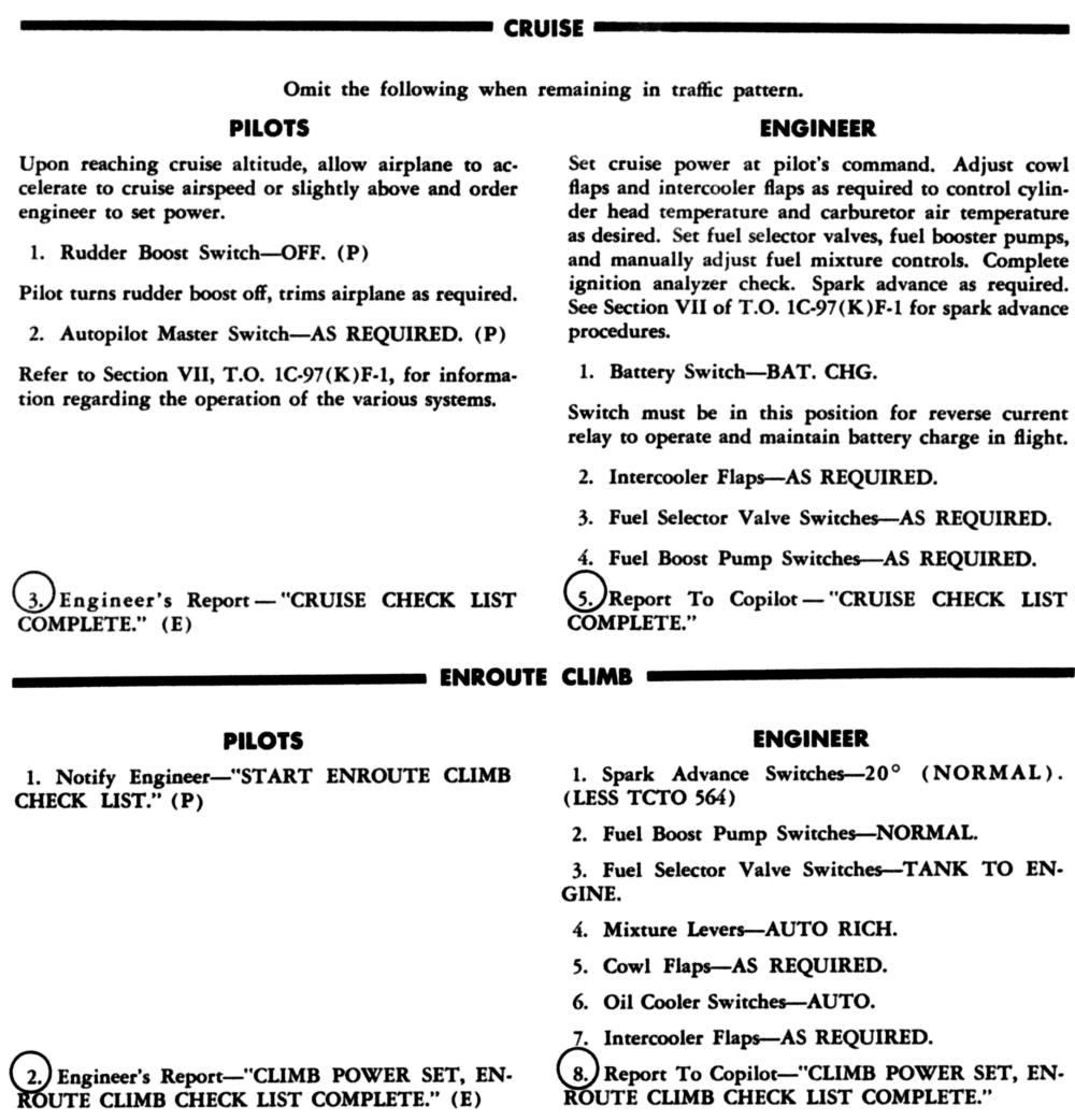
1. The aircraft was leveled off and allowed to accelerate to the charted cruise speed at climb power.
2. The calculated and corrected cruise power was set and engine operating temperatures allowed to stabilize with mixture controls in the Auto Rich position.
3. Manifold pressures were verified to be within allowable limits as specified in the power schedule charts.
4. An ignition analyzer scan was accomplished.
5. The following procedure was accomplished one engine at a time to set up a bhp of 1,735 per engine using 2,100 rpm and 158 psi indicated torque pressure.
A. Advance the throttle to 111% of the base torque (158 psi) to 175 psi
B. Establish best power mixture by slowly moving the mixture control from Auto Rich one knobs width while observing the torque meter. If indicated torque pressure remained the same Auto Rich is best power.
C. Continue to lean the mixture fairly rapidly to within 3 psi of base indicated torque pressure (158 psi).
D. Move the spark advance switch for that engine to the 30°, advanced, position and verify with ignition analyzer and an increase of 3 to 4 pounds of indicated torque pressure.
E. Lean mixture to the exact base value, 158 psi indicated torque pressure.
F. For greater overall cruise performance increase the manifold pressure 1".
G. Lean mixture to the exact base value, 158 psi indicated torque pressure.
H. Make final adjustments with cowl flaps to maintain 230°C cylinder head temperature and intercooler flap to maintain 20°C carburetor air temperature.
6. The above procedure was accomplished on the remaining three engines and the indicated airspeed was verified to insure that the charted value was being maintained. If you did it right and the aircraft weight was as predicted, you could usually beat the chart by one or two knots.
7. Cruise power settings were usually maintained for one hour after which a new power setting was computed, set and the engines leaned once again.
8. To return to normal 20° spark advance prior to changing power settings the mixture was enriched approximately 5 psi torque pressure, the spark advance switch moved to the 20° position, the throttle retarded and mixture control moved to Auto Rich simultaneously to retain the 158 base torque pressure.
We typically descended at cruising speed if flying conditions permitted. The most important thing to remember was to cushion the high inertia loads on the master rod bearings by maintaining at least 1" of manifold pressure per 100 engine rpm.
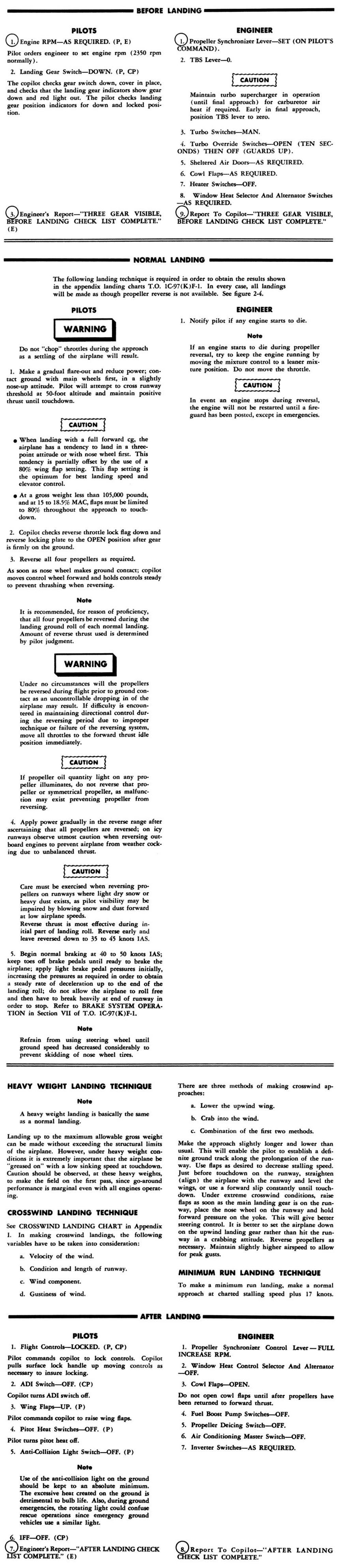
Positive power settings were best to help control engine temperatures. At some point during descent turbo supercharger operations were discontinued, depending upon weather conditions and the field elevation of the landing airport in order to depressurize the aircraft. Normally reverse thrust was used during the landing roll out until 50 knots indicated air speed. After departing the runway the engines were leaned to minimize spark plug fouling and the cowl flaps were opened to reduce cylinder head temperatures.
After the cylinder head temperatures had stabilized at 180°C or less it was very important to operate the engines at 1,000 to 1,200 rpm for one minute prior to shut down. Since the engine oil savage pumps had a greater pumping capacity than the oil pressure pump this would reduce the amount of oil that remained in the crank case and minimize the chance of cylinder liquid lock at the next engine start. In over nine years of operating R-4360 engines I only experienced one liquid lock on one engine. This occurred because one time I hurried the engine shut down and did not follow this important step.
The Air National Guard Group that I was associated with had nine C-97G aircraft. We had an exceptional and dedicated maintenance staff. But when operating 36 R-4360 engines, each with many moving parts, failures were bound to happen. The flight crews accepted this probability and trained appropriately. In my own nine years and 5,000-plus hours of having the pleasure of operating this fine example of engine technology here are some examples of the failure modes that I experienced:
1. Cylinder failures. One that I can remember involved the exhaust valve seat releasing from its shrink fit in the cylinder head and holding the exhaust valve open. Others caused by valve failures usually peened both spark plugs gaps closed resulting in the appropriate back fire and shorted secondary ignition analyzer indication.
2. A few internal oil scavenge pump failures. This caused all of the oil in the 32 gallon engine oil tank to fill the engine crank case in less than one minute.
3. Several failures of internal engine parts of unknown origin.
4. One failure was caused by a cam roller coming off of a single tappet causing an exhaust valve to remain closed in one cylinder. This was discovered by removing all 56 rocker box covers, motoring the engine over with the starter and observing that one valve did not open. The engine overhaul report pointed out the missing cam roller.
Despite the expectation of engine failures, the longest time that I ever had to fly on three engines was one and a half hours. Typically we anticipated at least 1,200 to 1,400 hours out of an engine and then expected something to go amiss. The highest time engine that I ever encountered was installed on an aircraft that I delivered to the bone yard and had just over 1,900 hours time in service since overhaul. It used all of the 32 gallons of oil in its engine oil tank and most of the oil in the 50 gallon central oil tank that enabled in flight oil transfer to any of the four engines. The flight took a little over seven hours.
Then there was the time when the copilot retracted the landing gear instead of resetting the flaps on a touch and go landing. But that’s another story.
United States Air Force, T.O. 1C-97G-1, 15 April 1964, Changed 1 June 1969
Federal Aviation Administration, Type Certificate Data Sheet E-247
Note: The R-4360-59B was not Type Certificated by the Federal Aviation Administration. There are at least seven models of the R-4360 that are Type Certificated
Send mail to
![]() with questions or comments about this web site.
with questions or comments about this web site.
![]()