
How Supersonic Inlets Work
Details of the SR-71 Mixed Compression Inlet Geometry and Operation
By J. Thomas Anderson
Technical Fellow Emeritus
Lockheed Martin Skunk Works
© Copyright Lockheed Martin Corporation
Presented 1 May 2014 at the 11th AEHS Convention
|
1.0 Summary
The SR-71 uses a mixed compression inlet, which was designed and developed by David H. Campbell, who holds a patent on that design. This vehicle is the only operational aircraft to fly sustained cruise at high Mach number (M = 3.2) and represents the first use of a mixed compression inlet in such an aircraft. This paper will give brief explanations of some basic physics involved in the supersonic compression process and then describe the problems of compressive flow and the solution methodology to these problems. Then the SR-71 inlet will be explained and used to illustrate solutions to these problems. Finally a more technical discussion of the SR-71 inlet is included for those readers who desire a deeper understanding of this subject.
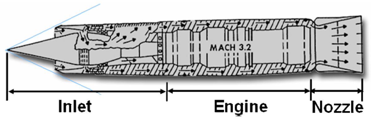 |
| Fig. 1 Example of an SR-71 Jet Propulsion System |
2.0 Introduction
This paper will discuss the requirements and operation of inlets in general with emphasis on supersonic inlets. The SR-71 inlet geometry and operation will be shown as examples of solutions to the problems of supersonic compression.
3.0 Applicable Physics
3.1 Mach Number
The speed at which a pressure signal can travel through the air is called the speed of sound. It is sensitive to the square root of the temperature. A Mach number of an aircraft is the ratio of the speed of that aircraft to the speed of sound.
3.2 Pressure
Air that is taken aboard an aircraft moving at a forward velocity has a property of elevated pressure resulting from that velocity called ram pressure or total pressure. An everyday illustration of this can be felt by stretching your arm out the window of a car moving at, let’s say, 70 miles per hour. A significant force will be felt on your arm. This pressure is much more significant at the higher speeds of an aircraft. The following table illustrates the ratio of this elevated pressure to the ambient or surrounding air pressure at different velocities.
| Vehicle | Velocity, mph | Mach Number | Pram Pambient | (Pram-Pambient) Pambient |
|---|---|---|---|---|
| Automobile | 70 | 0.1 | < 1.01 | < 0.01 |
| Airliner | 530 | 0.8 | 1.5 | 0.5 |
| Fighter | 1,300 max | 2.0 | 7.8 | 6.8 |
| SR-71 | 2,130 | 3.2 | 49.4 | 48.4 |
You can readily see that recovery of ram pressure, pressure recovery, becomes more and more important for efficient operation as aircraft fly faster and faster.
3.3 Continuity
A reigning law of physics is that air that flows into a container must go somewhere. It must flow out of the container or be stored as in a balloon. Aircraft structure will not act like a balloon. Therefore air that flows into the container or in this case, the inlet, must flow out of the container or inlet. This is called the law of continuity. The importance of this law will be apparent in later discussions of subsonic and supersonic inlet operation.
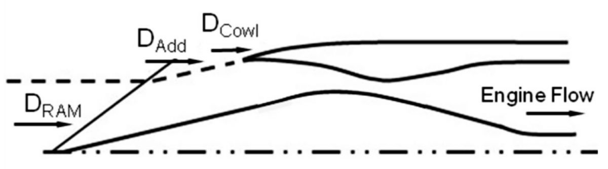 |
| Fig. 2. The dashed line in this sketch represents the boundary of the airflow stream tube that is taken aboard. Air on the outside of this boundary is spilled around the inlet and the drag associated with that spillage, Dadd,. The change in cowl drag due to that spillage, ΔDcowl, affects the aircraft’s efficiency. Also, the other flows that exit the inlet, like bypass flow and leakage flow, carry their own drag penalties. These flows will be described later. |
3.4 Drag
When air is taken aboard a flight vehicle, it is accelerated from zero velocity to approximately the velocity of the vehicle. Accelerating a mass of air forward requires energy and is felt as an impeding or downstream force, or drag, on the airplane. The sketch below, Figure 2, illustrates the drag forces felt on the inlet. Flow is going through this duct from left to right, entering the inlet on the left and exiting to the engine on the right. The term Dram represents the drag of taking air on board. It can vary from 25 pounds of force per pound per second of airflow for a subsonic vehicle to 100 pounds of force per pound per second at a Mach number of 3. Since the engine flow through can be a couple of hundred pounds per second, you can see that this drag is very substantial. Obviously, a basic requirement for a propulsion system is that most of the air entering the inlet be put through the engine and converted to useful thrust.
3.5 Temperature
Incidentally, just as pressure increases with velocity, temperature also increases. Temperature is a major problem; temperatures in the inlet can reach 800°F This paper will not delve into the temperature issue, but will discuss pressure recovery and the drag of taking air onboard.
3.6 Boundary Layer
You should also know that the flow near the inlet walls is slower than the flow in the main part of the inlet. In fact, the molecules right next to the wall are effectively stuck to the wall because of friction. This layer of low energy air causes many problems in the inlet flow because the higher downstream pressure feeds upstream and causes the flow to separate off the wall. This is an especially large problem in supersonic inlets and will be discussed later.
 |
| Fig. 3. |
3.7 Subsonic Inlet Principles
Let’s change our frame of reference from that of an aircraft moving through the air to that of a stationary aircraft with air moving towards it as in a wind tunnel. These two points of view are identical for the subjects we are about to discuss. Air enters the inlet and is diffused, the flow area is enlarged, as the air moves downstream towards the engine. This process reduces the velocity and converts the ram pressure to a useful pressure or a static pressure, which is the pressure of the air when it is brought to rest, zero velocity. This air is then given to the engine.
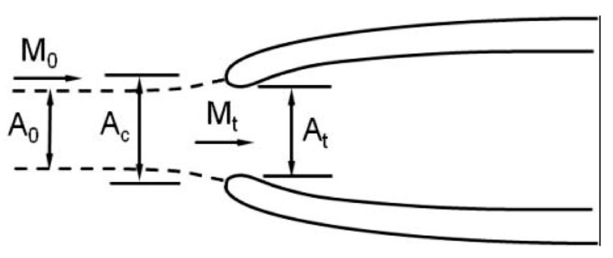
A subsonic inlet is illustrated in Figure 3. The term Ac denotes an area which defines the size of the inlet. The term At is the minimum area in the inlet, the throat area, and A0 is the area of the oncoming flow that will actually enter the inlet. Again, the dashed line represents the boundary of the air streamtube that is taken into the inlet.
It can be seen from the above discussion that air is brought into the inlet and pushed downstream into regions of higher and higher pressure. Air does not like this. It likes to flow from high pressure to low pressure as it does when it leaves the vehicle through the nozzle. The situation in the inlet is called an adverse pressure gradient and putting air through this is like pushing on a piece of string. If the pushing is done very carefully the string can be pushed. If the pushing is not done properly, the string will kink and refuse to be pushed. In contrast, air flowing out the nozzle is like pulling on the string. In this case the string will come along quite nicely. Therefore the inlet must be designed to treat the air very carefully, which means very gentle turns and slow diffusion, to prevent the airflow from separating from the inlet walls and forming eddies and vortices. If this is done properly, the available total pressure will be converted efficiently to static pressure.
In some ways designing a subsonic inlet is like setting out the course for a competition slalom skier. The pylons must be carefully placed to make the course challenging and still skiable for a competent skier. Information about the flow in the downstream regions of the inlet is propagated upstream at the speed of sound. Since the downstream flow in a subsonic inlet is less than the speed of sound, information about the downstream end of the inlet, including signals from the engine flow, are propagated to the front of the inlet. Thus the size of the entering stream tube is altered and the flow into the inlet is made to be equal to the flow leaving the inlet. In this way, continuity is preserved. A well designed subsonic inlet will recover 99% of the ram pressure or more. The drag of the spilled air, Dadd, will be cancelled by the decrease in the cowl drag, ΔDcowl, due to the extra air flowing around the cowl.
3.8 Supersonic Inlet Principles
Flow in a supersonic inlet is much more problematic than the flow in a subsonic inlet. The big difference is that flow moving faster than the speed of sound has no knowledge of what is ahead of it. The result of this makes the design of a supersonic inlet similar to laying out the course for a slalom skier, only in this case the skier is blind.
 |
| Fig. 4. |
3.8.1 Supersonic Compression
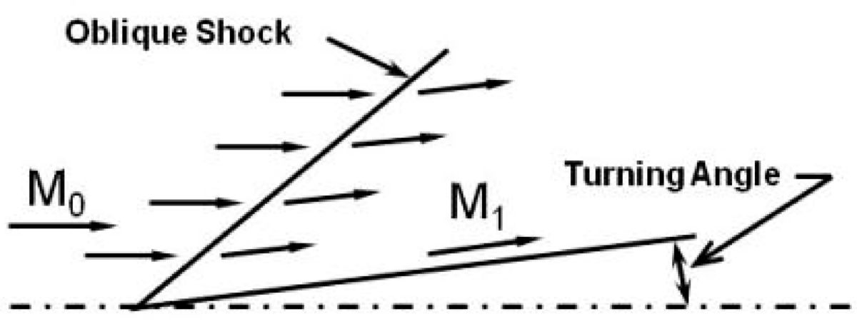
Supersonic flow velocity is changed, compressed or expanded, by changes in flow direction. Because supersonic flow is unaware of what is ahead of it, it does not react to a surface change of slope until the flow is downstream of the surface change. The line along which such a change occurs is a sloped line and is known as a compression ray or, for more substantial changes, an oblique shock. Figure 4 illustrates this phenomenon. An abrupt change in flow direction, which produces an oblique shock, causes an attendant loss of ram pressure. Careful design, small, gradual changes in flow direction, holds these losses to small values.
 |
| Fig. 5. |
A supersonic inlet is made up of two distinct parts. First the flow is compressed supersonically from the velocity of the flight vehicle or, in other words, the free stream Mach number. This is done by reducing the flow area as the flow proceeds downstream. In this region the flow velocity is reduced through a series of compression waves and/or oblique shocks. Flow velocity is reduced to a minimum speed at the duct minimum area, called the throat of the inlet, where the flow approaches sonic velocity or a Mach number of one. At this point the flow Mach number will be reduced from supersonic, above one, to subsonic, below one, through a normal shock. This begins the second part of the inlet, the subsonic diffuser. In this region the velocity is reduced as the flow area is increased. The result of this process is conditioned air, smooth, subsonic air at high pressure, which is then delivered to the engine. Figure 5 illustrates the parts of a supersonic inlet. Note the dashed line that denotes the boundary of the air entering the inlet, the capture area, Ac, which is the entire area of the cowl lip, and the minimum area or throat area, At.
3.8.2 Inlet Supersonic Contraction
As the flight velocity changes, the amount of contraction required to reduce the free stream Mach number down to a throat Mach number near one varies. This results in a requirement for the throat area to change as flight speed is varied, which means the inlet must have variable geometry.3.8.3 Inlet Flow Balance
Another item that results from the fact that supersonic flow is blind is the requirement for a flow escape valve between the inlet throat and the exit or engine face. Once the supersonic flow is captured in the inlet, that flow rate is set and constant. The exit can change, however, due to variations in the system like changes in engine airflow. A valve is then required to keep the inlet and exit flows consistent, thereby maintaining continuity. This valve, which is called an inlet bypass door, is required to be variable and controlled by a control system that senses duct pressure and constantly works to keep that pressure constant which maintains the airflow match between the inlet outflow and the engine inflow.
3.8.4 Inlet Unstart
A very significant event can occur because supersonic flow is blind. Occasionally, exit flow will reduce faster than the inlet bypass door can handle or the throat area will mischedule to too small an area. When this happens the inlet exit flow will be reduced but the flow will continue to enter the inlet at the same rate because the entering flow is unaware of what is happening downstream. The result of this imbalance is a violent breakdown of the supersonic flow in the inlet and the establishment of subsonic flow through the inlet and out in front of it. This then allows the spillage in front of the inlet to change, rebalancing the flow in with the flow out, thus reestablishing continuity. This change in the compression process is known as an inlet unstart and results in a very violent yawing and banging on the aircraft. Inlet unstarts can be prevented by careful design, adequate wind tunnel data definition, and a reliable control system.
4.0 The SR-71 Airplane
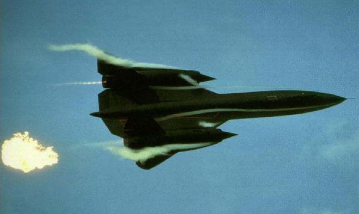
The vehicle known as the SR-71 was one of the most phenomenal flight vehicles ever built. It was filled with technical innovations that solved the problems of sustained high speed cruise. The airplane made, and I am quoting from page 241 of Ben Rich’s book Skunk Works, “… total of 65 million miles of flying, mostly at three times the speed of sound.” A picture of the aircraft lighting the right hand afterburner with a TEB (triethyl borane) shot is shown in Figure 6.
Design of the inlets for the vehicle’s JT11D-20 (J58) engines was a huge problem. I am quoting Ben Rich again from page 206 of his book “Our crown of thorns was designing and building the powerful engine’s inlets - the key to the engine’s thrust and its ability to reach blistering speeds. This became the single most complex and vexing engineering problem of the entire project.” The problems involved with this design were solved one by one, mostly by David H. Campbell, the inlet design lead.
 |
 |
 |
| Fig. 6. | Fig. 7. | Fig. 8. |
4.1 SR-71 Inlet System
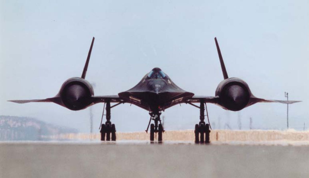
The SR-71 inlets are axisymmetric, mixed compression, translating spike inlets located ahead of the wing and behind the vehicle leading edge shock. The inlets are each canted down 5.6° and inboard 3.2° in order to align their centerlines with the oncoming flow as influenced by the vehicle forebody at the design flight condition. The following cartoon, Figure 7, exaggerates the pointing of the inlets into the local wind. Figure 8 also illustrates the downward and inboard canting of the inlets.
4.2 Inlet Geometry
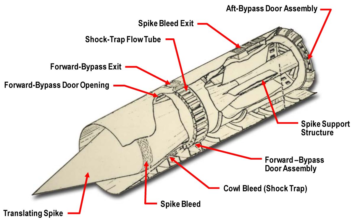
The inlet centerbody and spike are supported in the inlet cowling by four struts. These struts support the fixed centerbody barrel which, in turn, supports and guides a translating spike. This spike translation is scheduled with flight Mach number and vehicle attitude and provides the variations of contraction and spillage required for inlet operation. More about this later. By the way, all versions of the airplane, A-12, YF-12, and SR-71 employ the same inlet and propulsion system. The supersonic and subsonic compression regions are located on a straight centerline from the tip of the spike aft to approximately the beginning of the struts. This portion of the inlet is canted for flow alignment. The flow is realigned with the vehicle reference line by a gentle bend through a constant area section between the beginning of the struts and the engine face. This bend causes each strut to be different and unique. Figure 9 defines the inlet and all its parts.
 |
 |
| Fig. 9. | Fig. 10. |
4.3 Spike Translation
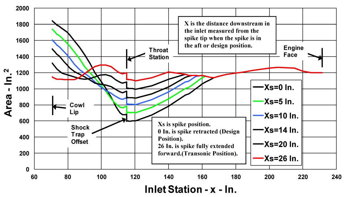
Spike position is defined by the term Xs. The spike translates aft from the full forward position, Xs = 26 inches, at Mach numbers of 1.6 and below to Xs = 0 inches, the design position, at Mach number 3.2, the vehicle design cruise speed. This varies the contraction from the capture area, Ac to the throat area At, and also the spillage around the cowl lip. Figure 10 is a chart of the duct flow areas plotted against the distance between the cowl lip and the engine face at various positions of the spike, Xs. Note the contraction or area reduction in front of the inlet throat at Xs = 0 inches and the elimination of that contraction as the spike is extended forward to Xs = 26 inches. The inlet capture area, Ac, is 18.7 ft² and the lip radius is 29.3 inches.
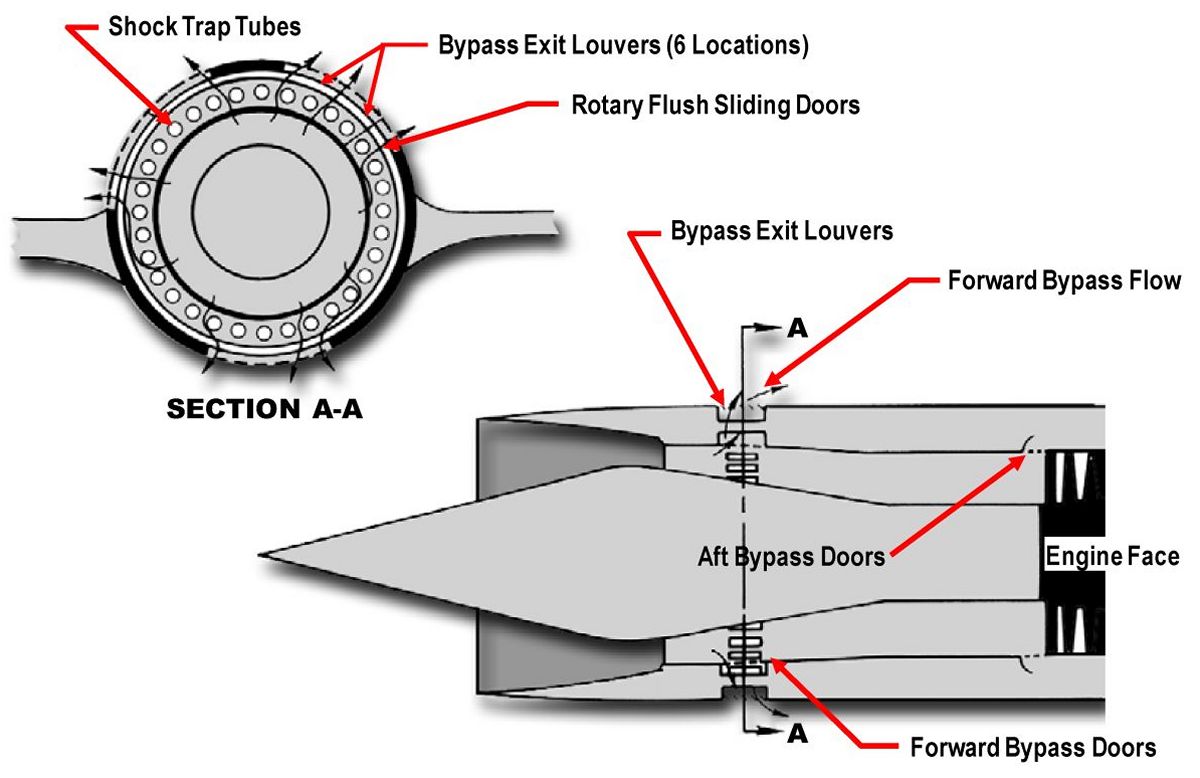
4.4 Forward Bypass Doors
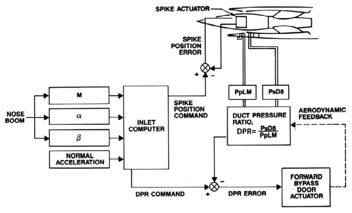
The forward bypass doors are the valves which, if properly controlled, insure that the flows in and out of the inlet are equal, or that continuity is maintained. These doors are a series of small ports around the circumference of the inlet cowl located a short distance downstream of the throat. These ports are covered by a ring of solid plates that rotates to vary the flow area through the holes. This bypass arrangement, known on the project as the cabbage slicer, is illustrated in Figure 11. The bypass flow area must be continually varied, in supersonic flight, to handle inlet flow changes and maintain continuity and prevent unstart. A computer control system is employed in the SR-71 to position the bypass doors and maintain an inlet flowing normally at high performance. This control system senses duct static pressure downstream of the throat, PsD8, ratios it to an external pressure, PpLM, and compares that ratio, which is called Duct Pressure Ratio or DPR, to a scheduled value that is determined from the vehicle flight Mach number, angles of attack and sideslip, and g loading. The control system then moves the bypass doors, which changes the inlet flow and pressure, to make the duct pressure equal to the desired scheduled pressure. A block diagram of this control system which controls the spike position as well as the forward bypass position is shown in Figure 12.
 |
 |
 |
| Fig. 11. | Fig. 12. | Fig. 13. |
4.5 Aft Bypass Doors
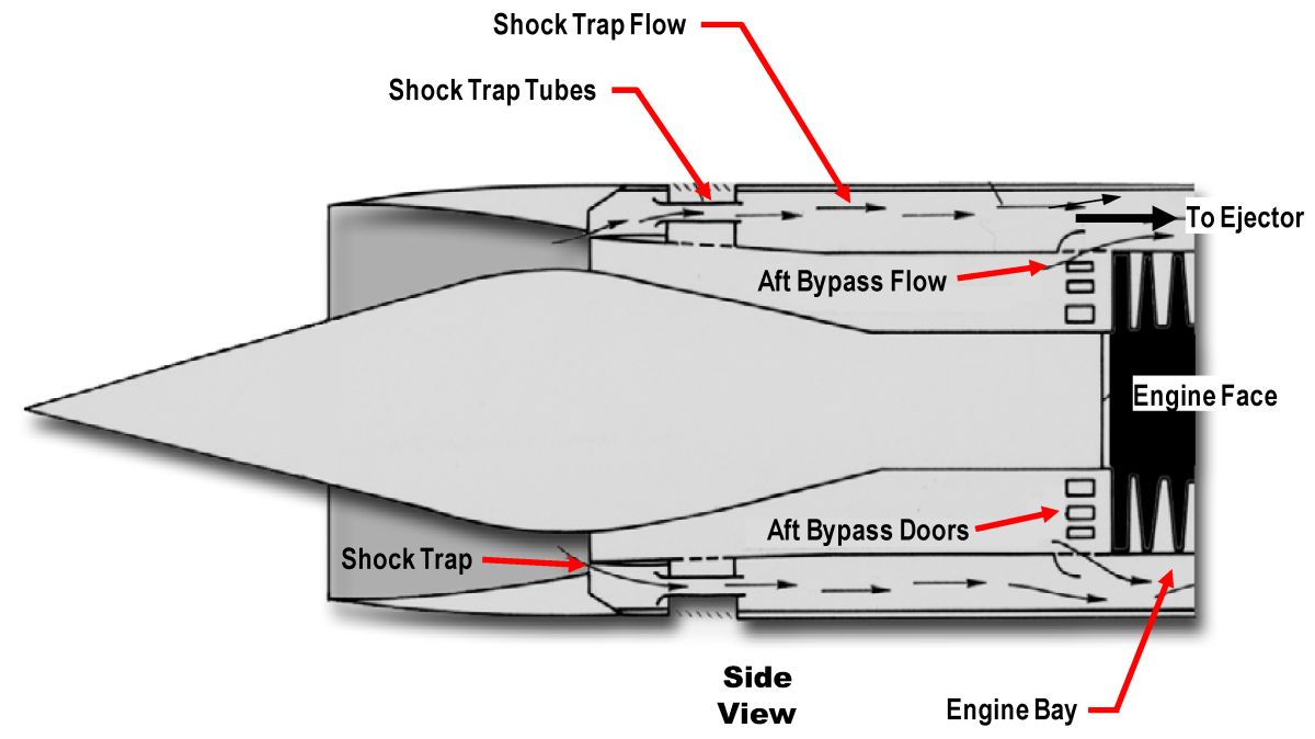
A second bypass, the aft bypass doors known on the project as the onion slicer, was added to the inlet at the engine face during the flight test development of the vehicle. This increased the total bypass capability of the inlet in order to enable descents at low airflow, low power, without unstarting the inlet. The aft bypass flows into the engine compartment and exits aft through the ejector to the nozzle. This flow route is shared with the cowl shock trap bleed and too much aft bypass flow can block the cowl bleed quantity and cause inlet unstart. Consequently, the aft bypass flow is limited and manually controlled to a simple schedule versus Mach number as shown in Table 2. Figure 13 shows the combined flow path of the shock trap bleed and the inlet aft
| Position | Opening | Mach Number |
|---|---|---|
| Closed | 0 | 0 - .7 |
| Position A | 15% | 1.7 - 1.9 |
| Position B | 50% | 1.9 - 2.7 |
| Position A | 15% | 2.7 - 3.0 |
| Closed | 0 | 3.0 and Above |
4.6 Inlet Bleed
Boundary layer is always a problem in an inlet and particularly in a supersonic inlet. The SR-71 handles this problem by bleeding off air at the surfaces on the cowl and spike in the throat region. These bleeds stabilize the interaction of the boundary layer and the normal shock in order to allow the inlet to operate stably at high performance.
 |
| Fig. 14. |
4.6.1 Cowl Bleed
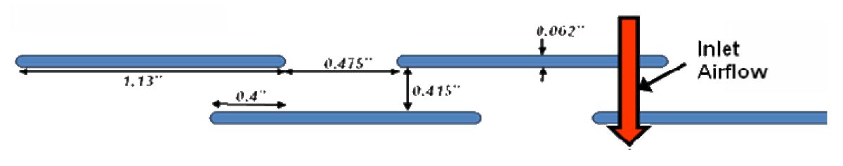
The cowl bleed is known as a shock trap bleed. A shock trap design is a ram bleed with a relieved internal flow area which allows the bleed to flow properly. A sketch of this bleed is shown in Figure 14.
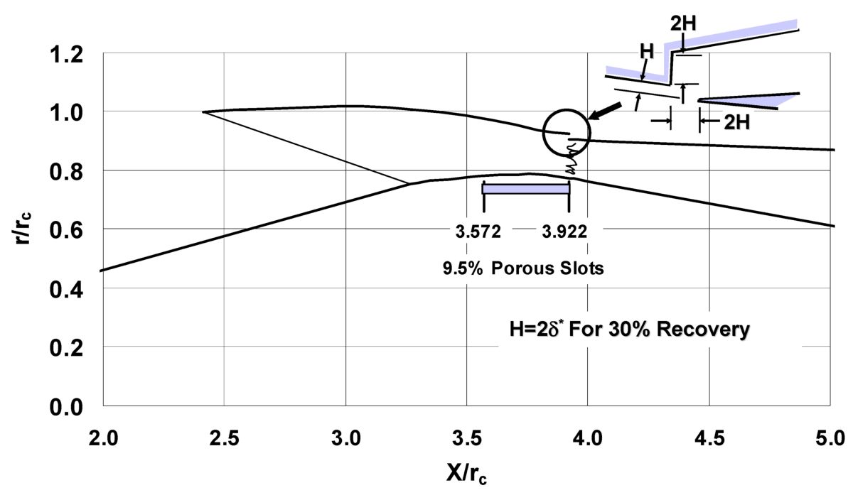
The basic inlet contours are designed as though the boundary layer is nonexistent. The amount of boundary layer displacement thickness, d*, is then estimated through the supersonic part of the inlet. Next the contour is relieved by that displacement thickness to provide adequate flow area including the presence of the boundary layer. The contour of the cowl of the SR-71 inlet was relieved by double the estimated boundary layer displacement thickness forward of the throat while the contour was held at the no boundary layer design value at the throat and downstream. This provided a step in the contour at the throat which then became the entrance to the shock trap bleed. The spike surface was not relieved. The result of doubling the relief at the cowl throat and the resulting doubling of the entrance to the shock trap bleed was a higher pressure value in the bleed flow channel and a more energetic and capable flow exiting the vehicle through the nozzle.
After the bleed air enters the shock trap, it is routed through tubes in the forward bypass hardware and aft through the engine compartment. The engine compartment is the annular volume between the engine and the outer skin of the nacelle. The bleed air ventilates and cools this volume on its way aft to flow overboard through the ejector nozzle. See Figure 17 for a sketch of the shock trap bleed flow path. See the Flow Distribution Section and Figure 24 for a definition of the various flows through the propulsion nacelle.
 |
| Fig. 15. |
4.6.2 Spike Bleed
Boundary layer is removed from the spike side of the inlet by 10 inches of porous surface located 2.17 inches ahead of the throat. The porous bleed hole pattern is shown in Figure 15.
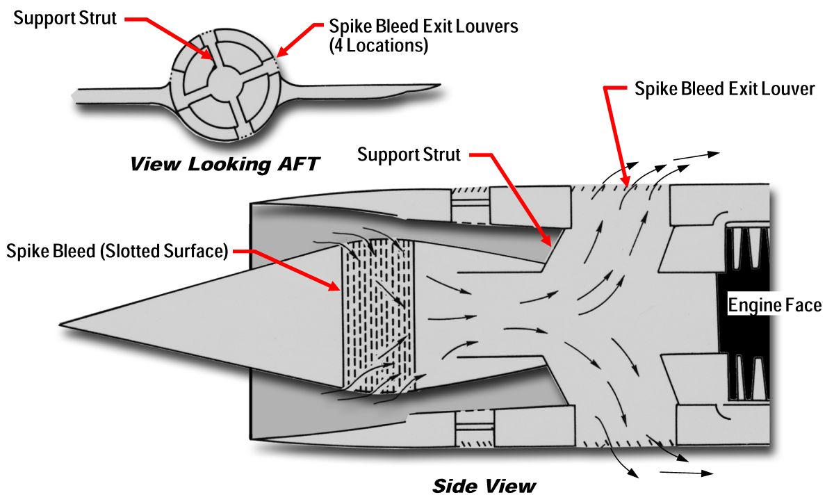
Spike bleed air flows through the bleed slots into the translating spike and then enters the front of the fixed centerbody. The air continues through the fixed centerbody, out the four struts, and then flows overboard through louvers. This flow path is illustrated in Figure 16. Figure 17 is another sketch showing the various secondary flow paths through the inlet.
 |
 |
| Fig. 16. | Fig. 17. |
4.7 Mice
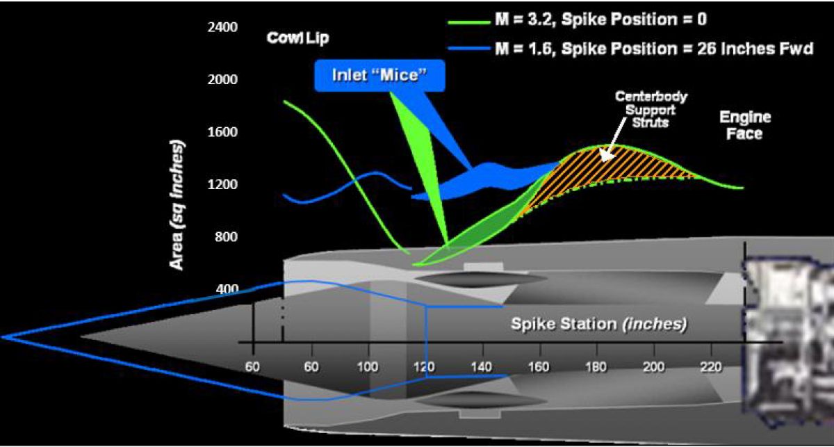
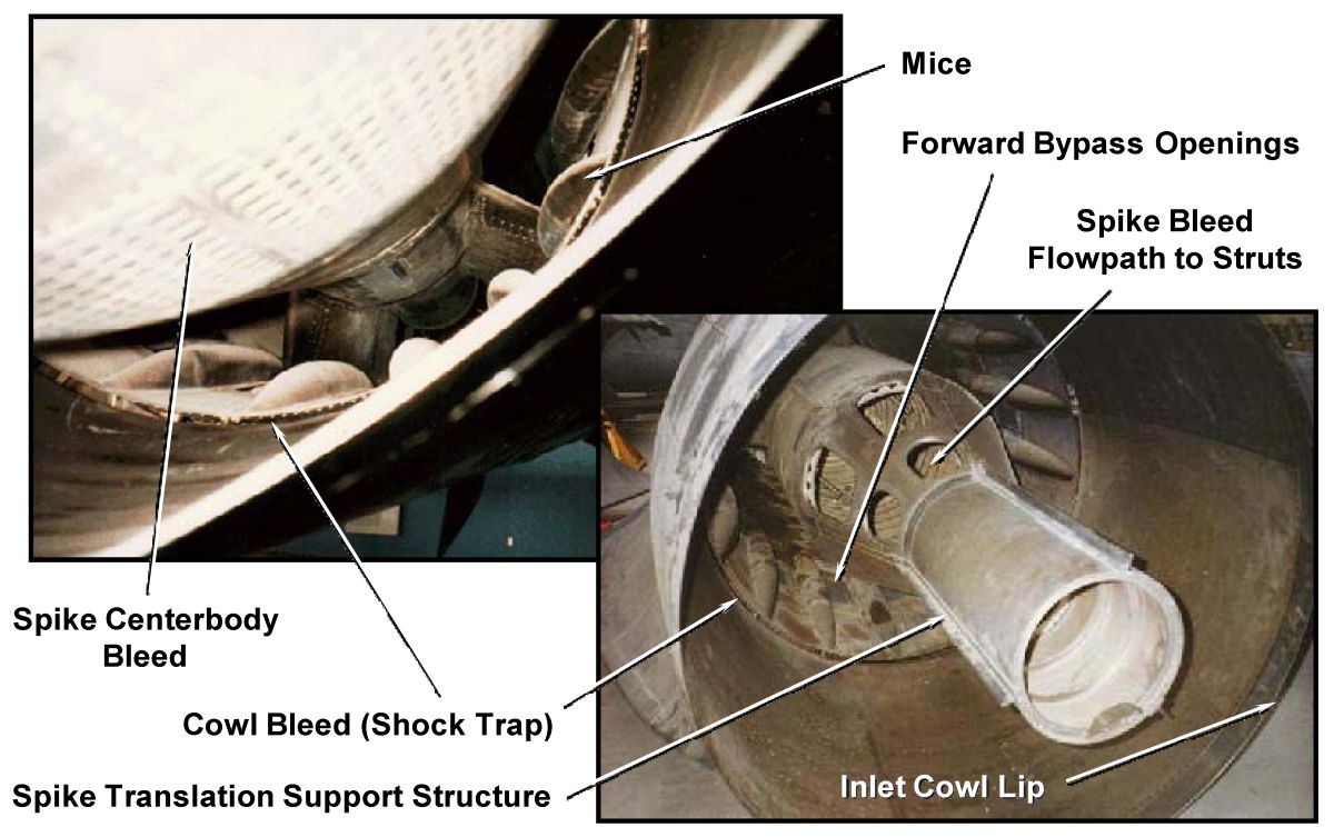
The original subsonic duct expanded too rapidly immediately downstream of the throat. The effect of this was lower pressure recovery and roughness in the duct that was felt by the pilot. The flow area needed to be reduced in this region in order to reduce the rate of expansion and control the flow diffusion. This was accomplished by adding area to the cowl. Since this is the same region where the forward bypass ports are located, the area was added in the form of bumps between the bypass ports. These lumps were known on the project as mice. Figure 18 shows the duct area progression versus distance aft along the inlet, with and without mice, with the spike in two positions. The first position is the aft or design location and the second position is the forward or transonic location. The area of the centerbody struts is also indicated. Figure 19 is a picture of the mice, forward bypass, shock trap bleed, and the spike bleed flow path.
 |
 |
| Fig. 18. | Fig. 19. |
4.8 Leakage
An inlet is a pressure vessel. This means that it holds a pressure above that of the surrounding air. The SR-71 pressure increment is about 25 psi or approximately two atmospheres. This duct pressure difference causes leakage of air out of the duct. This leakage exits with no thrust recovery, because it has lost all its pressure in the process of leaking and therefore causes a significant drag on the airplane. A flight nacelle was modified to seal up various inlet flow paths and pressure tested. Various flow paths were opened and the resulting leakage measured. A picture of this test article was shown in Figure 20 and a schematic of the sealing arrangement is shown in Figure 21.
 |
 |
| Fig. 20. | Fig. 21. |
The inlet was found to leak a significant amount, particularly through the variable geometry pieces of the inlet, namely the two bypass doors and the aft end of the translating spike. The largest leak by far was through the forward bypass doors. This leakage is only a problem when the doors are closed. When they are open the leakage is just part of the bypassed air. The difficulty of sealing these passages was the fact that the seals had to withstand temperatures up to 800°F, which precluded the use of conforming, nonmetalic seals.
5.0 Technical Details
The following discussions explore some regions of the inlet technology in more detail and are provided for the reader who desires some additional technical depth.
5.1 Inlet Pressure Recovery
The total pressure recovery of the inlet is shown in Figure 22. The orange symbols denote the started inlet recoveries at various Mach numbers at nominal angle of attack. Recoveries of the unstarted inlet are shown in red. Notice the huge difference between the normal operating and unstarted values.
5.2 Inlet Operating Map
An explanation of an inlet operating map might be of interest to the serious reader. This performance map, shown in Figure 23, is a chart of inlet pressure recovery, engine face ram pressure ratioed to the ram pressure available in front of the inlet versus mass flow ratio, flow exiting the inlet to the engine ratioed to the flow that would enter the full cowl area. Let’s assume we are operating happily at Point 1. If the exit flow is reduced a bit, the normal shock and attendant pressure field moves forward in the throat region. This will produce a higher recovery and the higher pressure will push more flow out the bleed, resulting in less flow exiting the inlet to the engine. This process will take the inlet from Point 1 to Point 2. Point 2 represents the point beyond which the inlet will unstart and the distance from Point 1 to 2 represents the inlet stability margin. Point 3 is the unstarted point. The pressure and flow unstarted are about a quarter of the started values at Mach number 3.2. This change occurs almost instantaneously and is another illustration of the violence of the inlet unstart.
Now the inlet has to be restarted. First the spike must be extended to open the throat area and the bypass opened, Point 3 - 4, in order to flow the required air out of the inlet at the low unstarted pressures. The inlet will restart, Point 4 – 5, the spike is then retracted, Point 5 – 6, and the bypass closed, Point 6 – 1. This brings the inlet back to the original operating point.
 |
 |
| Fig. 22. | Fig. 23. |
 |
| Fig. 24. |
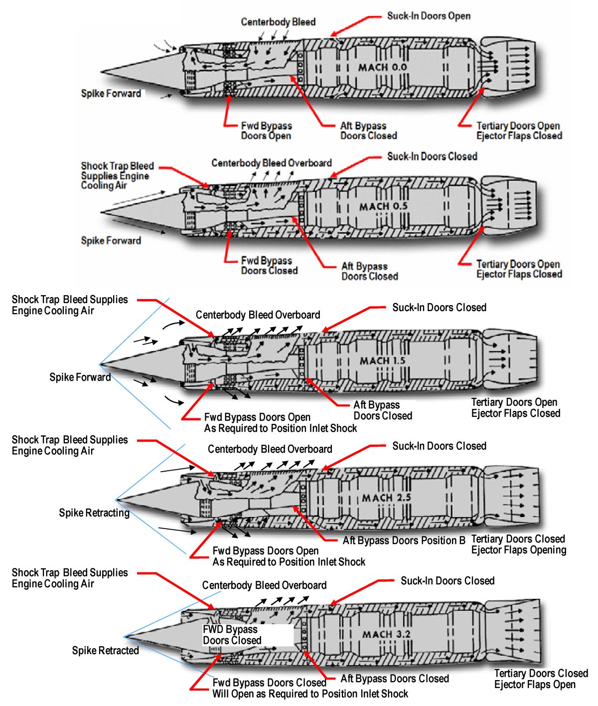
5.3 Flow Distribution
There are multiple flow paths through the propulsion nacelle and these paths change at various flight speeds. Figure 24 illustrates these flow paths throughout the flight envelope.
The following nacelle geometries change with Mach number in addition to the inlet geometries discussed previously. Suck in doors open at low speeds to maintain small pressure loads on the nacelle skin. Tertiary doors open at low and transonic speeds to allow additional air into the nozzle to help fill the exit. The exit flaps are variable and help the available air fill the exit by closing down at low speed and opening wide at high speed.
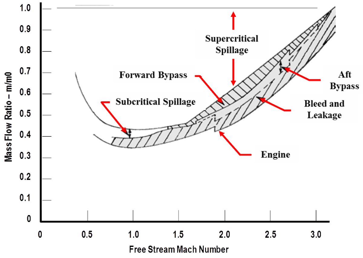
Figure 25 defines the quantities of these flows in terms of mass flow ratio. Mass flow ratio is the ratio of a flow divided by the flow that would be passed through the inlet cowl area. In other words, an inlet that accepts all the air approaching it would be flowing at 100% mass flow ratio. Figure 25 begins with the engine flow at the bottom of the chart and adds the various inlet flows onto the engine flow. When all the flows are added together the total is 100%. Note that supercritical and subcritical spillage are very similar, supercritical spillage is ahead of the normal shock and subcritical spillage is downstream of the normal shock. Both flows pass around the outside of the cowl and result in spillage drag.
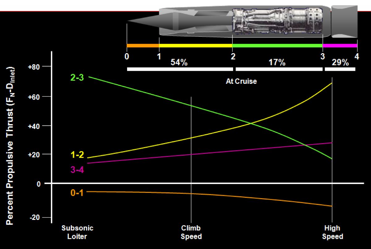
5.4 Thrust Distribution
As the flow proceeds though the propulsion nacelle, it produces forces that are distributed throughout the nacelle. Figure 26 shows the distribution of force between the inlet, engine, and nozzle through the flight envelope. Notice that the majority of the thrust is felt in the inlet as the speed is increased up to the design speed. This is a result of the high pressure air in the subsonic diffuser pushing forward on the spike.
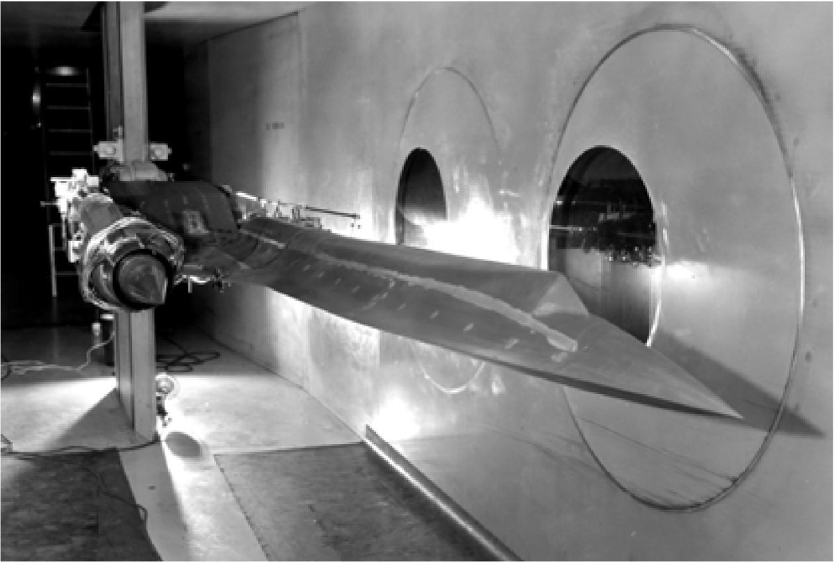
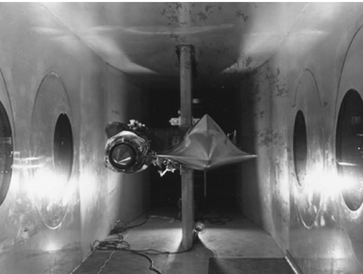
5.5 Wind Tunnel Test
The inlet configuration, operational performance, and bypass control pressure schedules were developed during a test conducted over seven weeks at the NASA Ames Unitary Wind Tunnels at Moffett Field, California. The inlet configuration was developed at the design Mach number of 3.2 in the 8 X 7 foot leg of the wind tunnel and then the data filled out through the flight envelope in the 8 X 7 foot, 9 X 7 foot, and 11 foot wind tunnel legs. Photos of the model are shown in Figures 27-29.
The inlet model was 1/8th scale. The scale was small so that the vehicle forebody could be included with the inlet model. This was done in order to capture the forebody flow distortions and effects in the inlet data.
 |
 |
| Fig. 25. | Fig. 26. |
 |
 |
 |
| Fig. 27. | Fig. 28. | Fig. 29. |
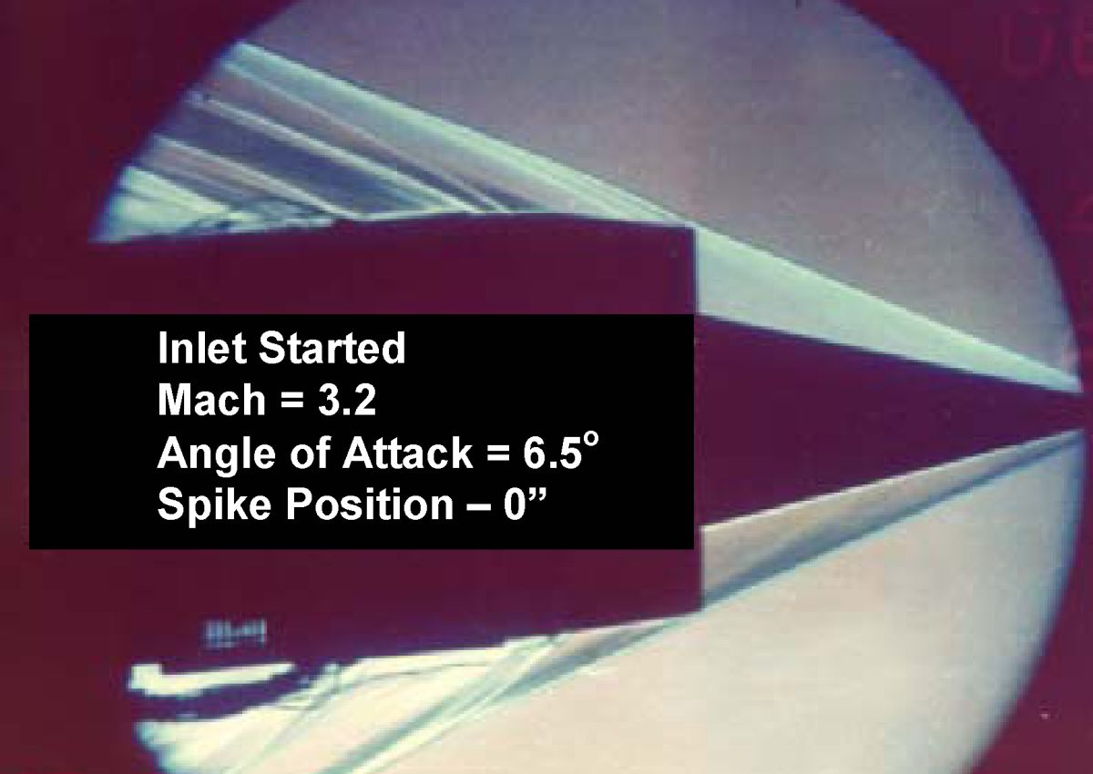
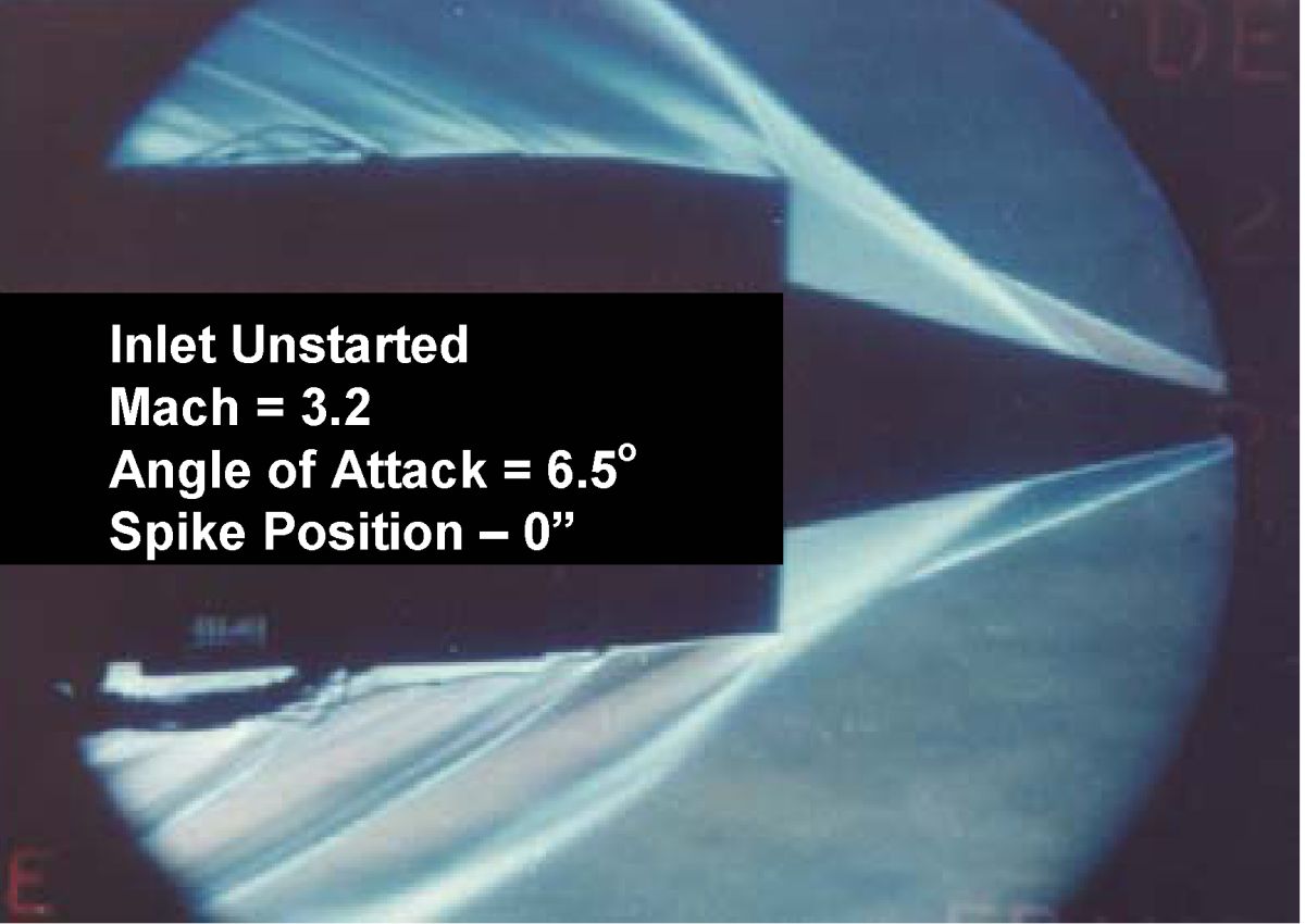
A certain type of picture of the airflow around a model is available in a wind tunnel. These pictures are called Schlierens and they show air density changes and as such show shock waves. Schlieren pictures of the SR-71 inlet flow were taken with the inlet started, operating properly, and unstarted, subsonic flow extended out in front of the inlet, are shown in Figure 30. A major change in the flow is evident, which indicates the violence involved with an inlet unstart.
 |
 |
| Fig. 30. | |
Send mail to
![]() with questions or comments about this web site.
with questions or comments about this web site.
![]()