
Napier Model Engines
by Clen Tomlinson
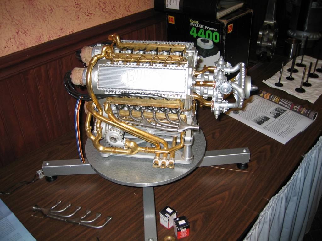
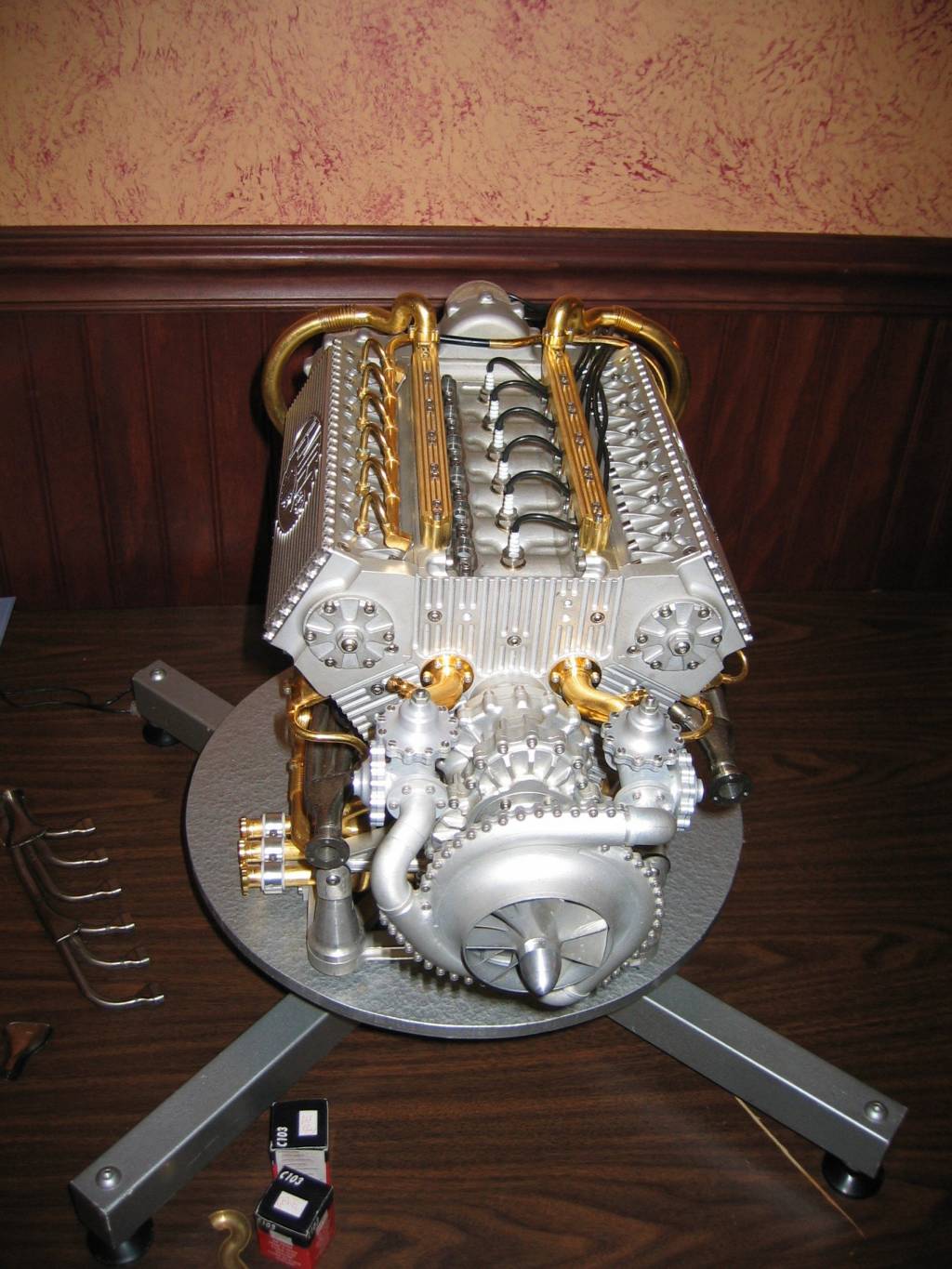
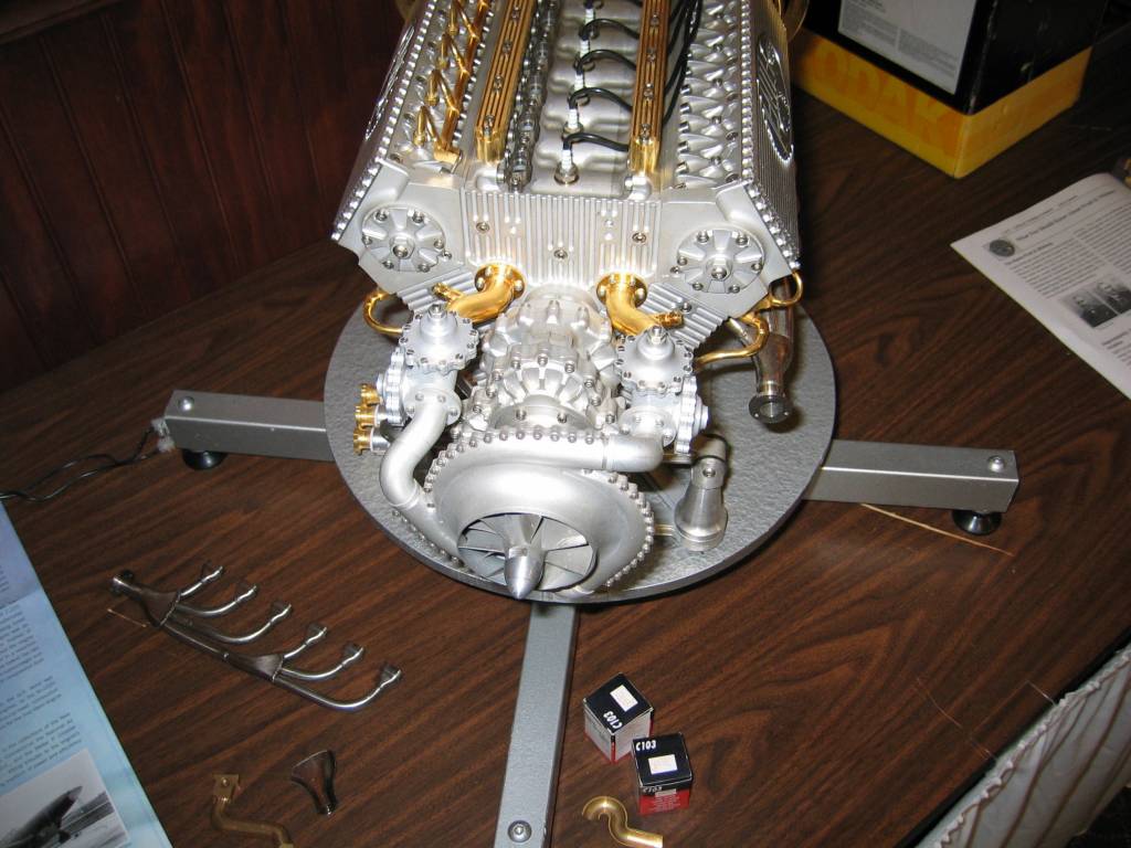
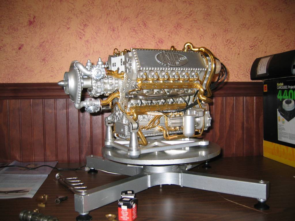
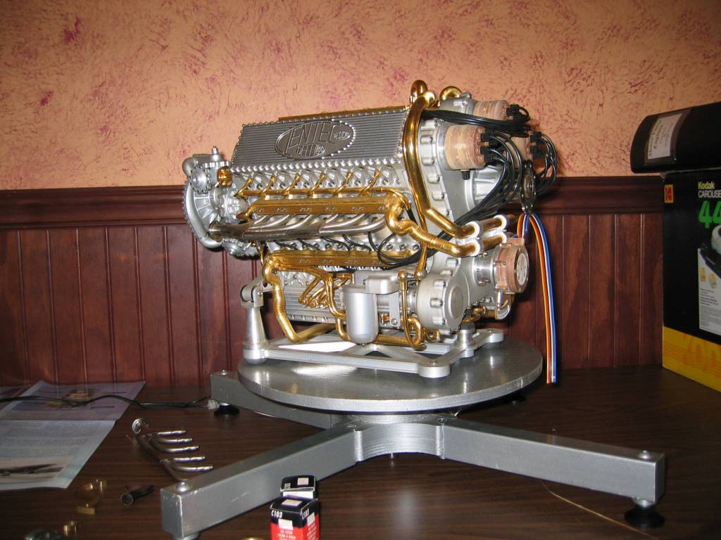
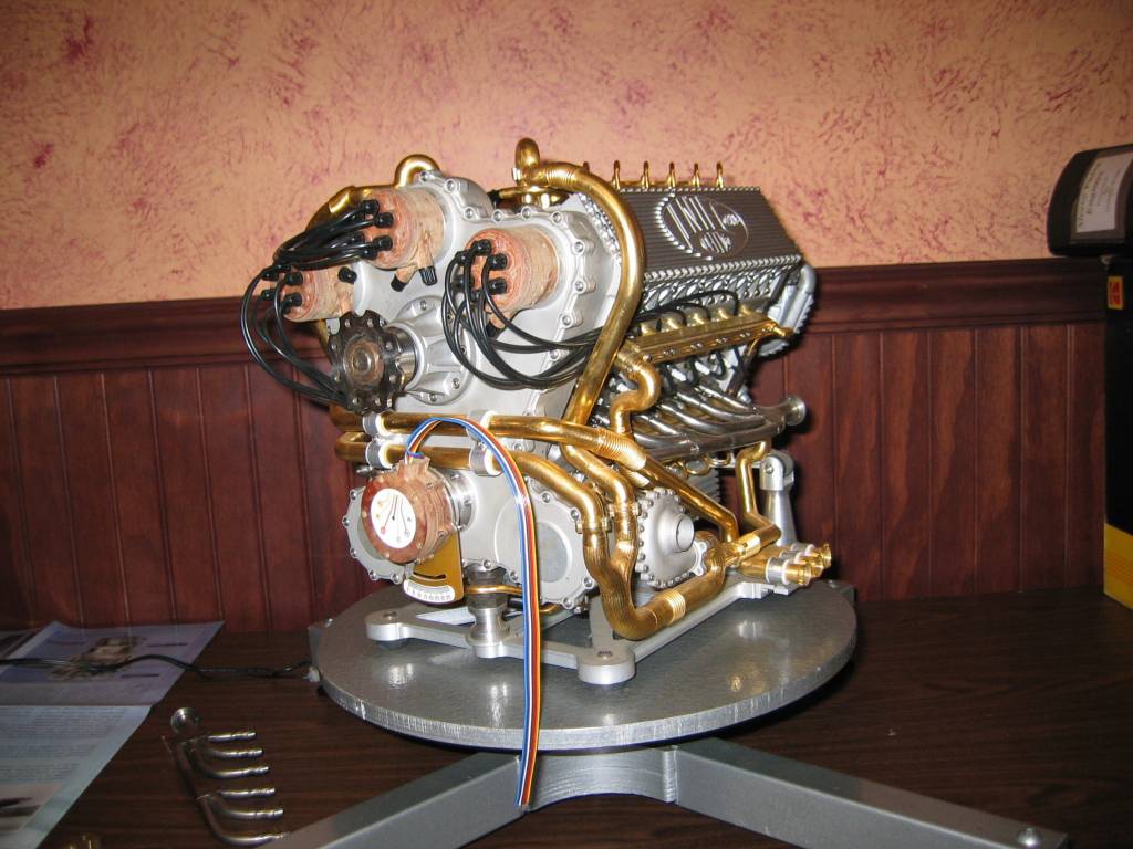
1/8th Scale Napier Deltic
|
|
|
|
|
|
|
|
|
|
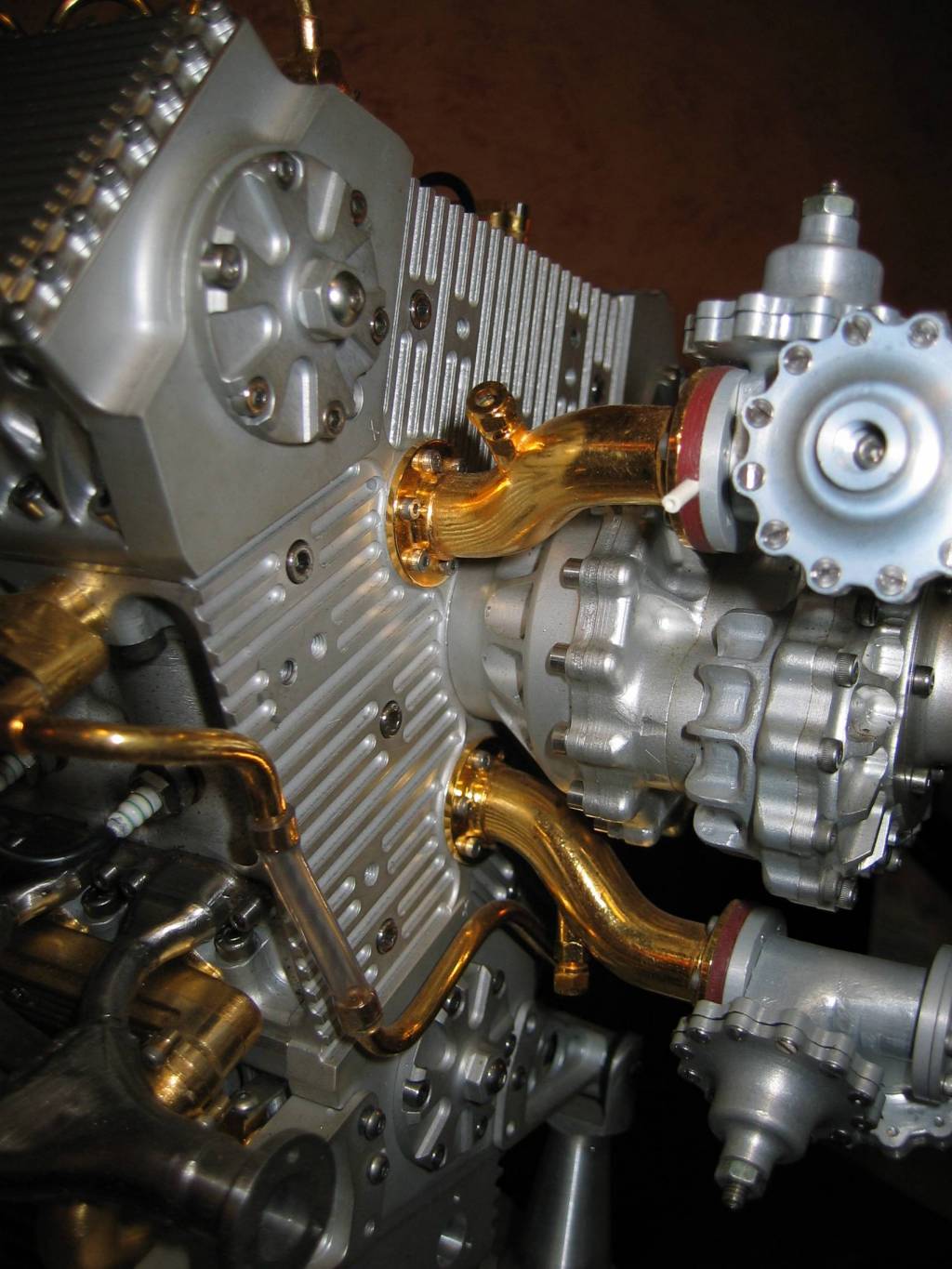
1/4 Scale Napier Sabre
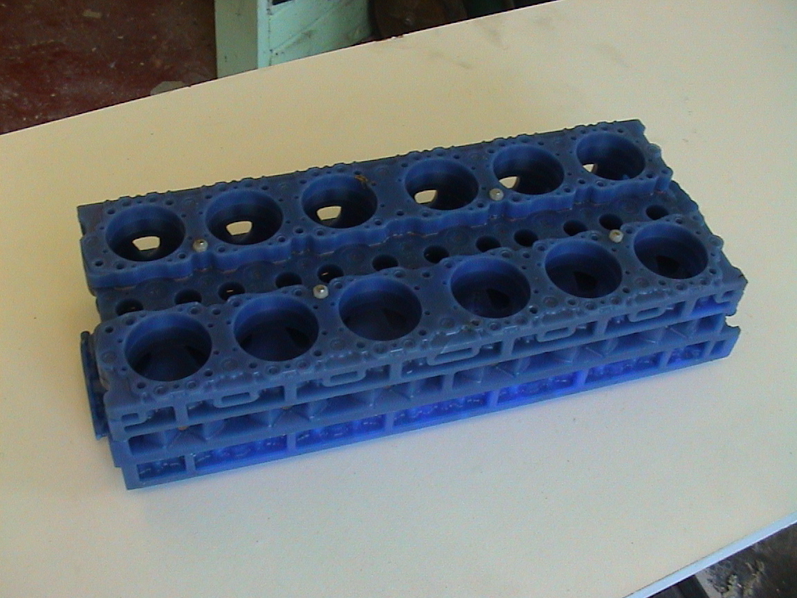
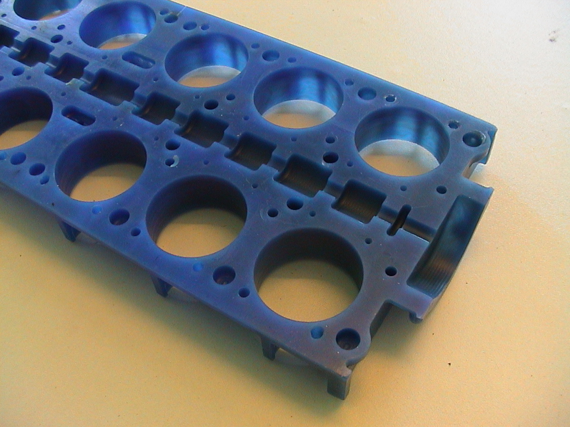
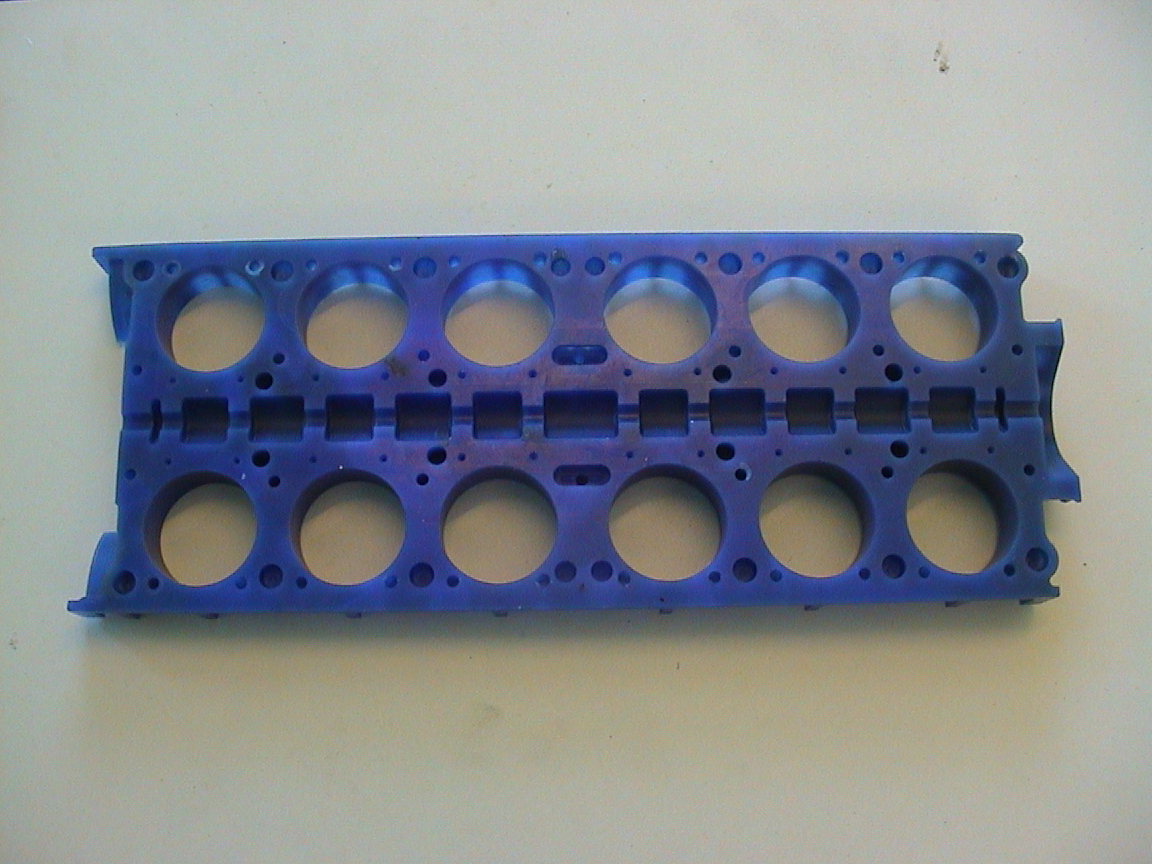
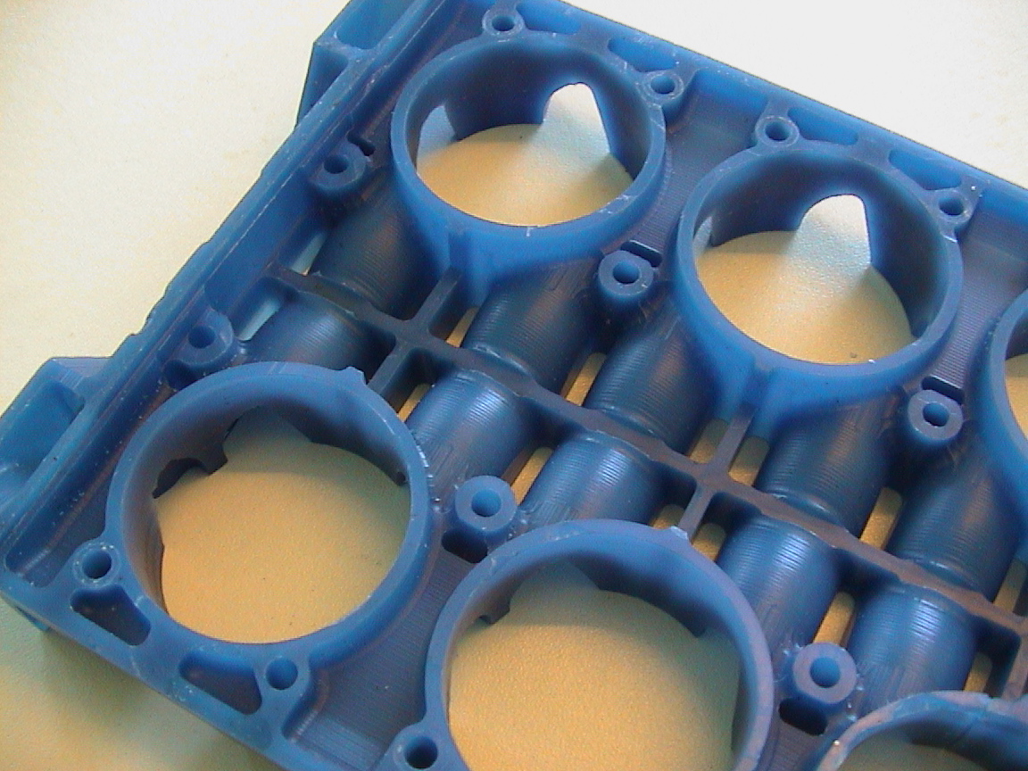
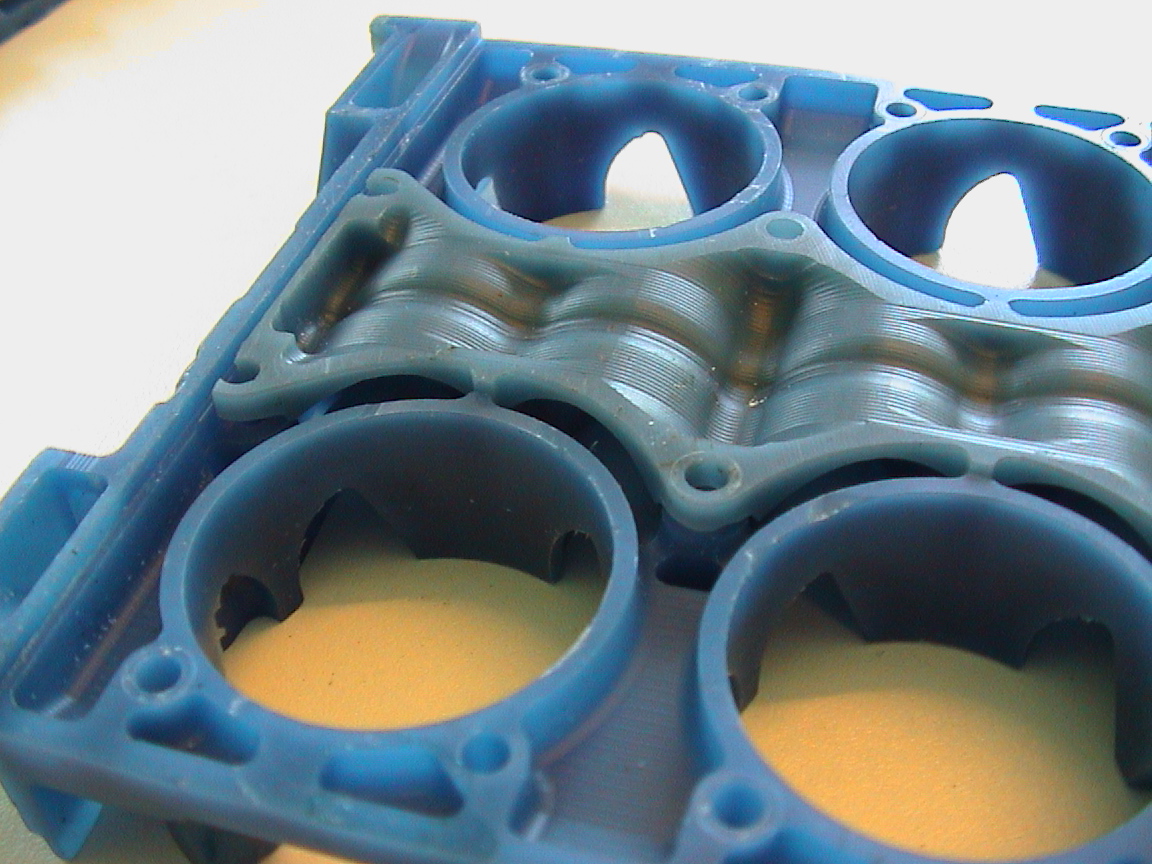
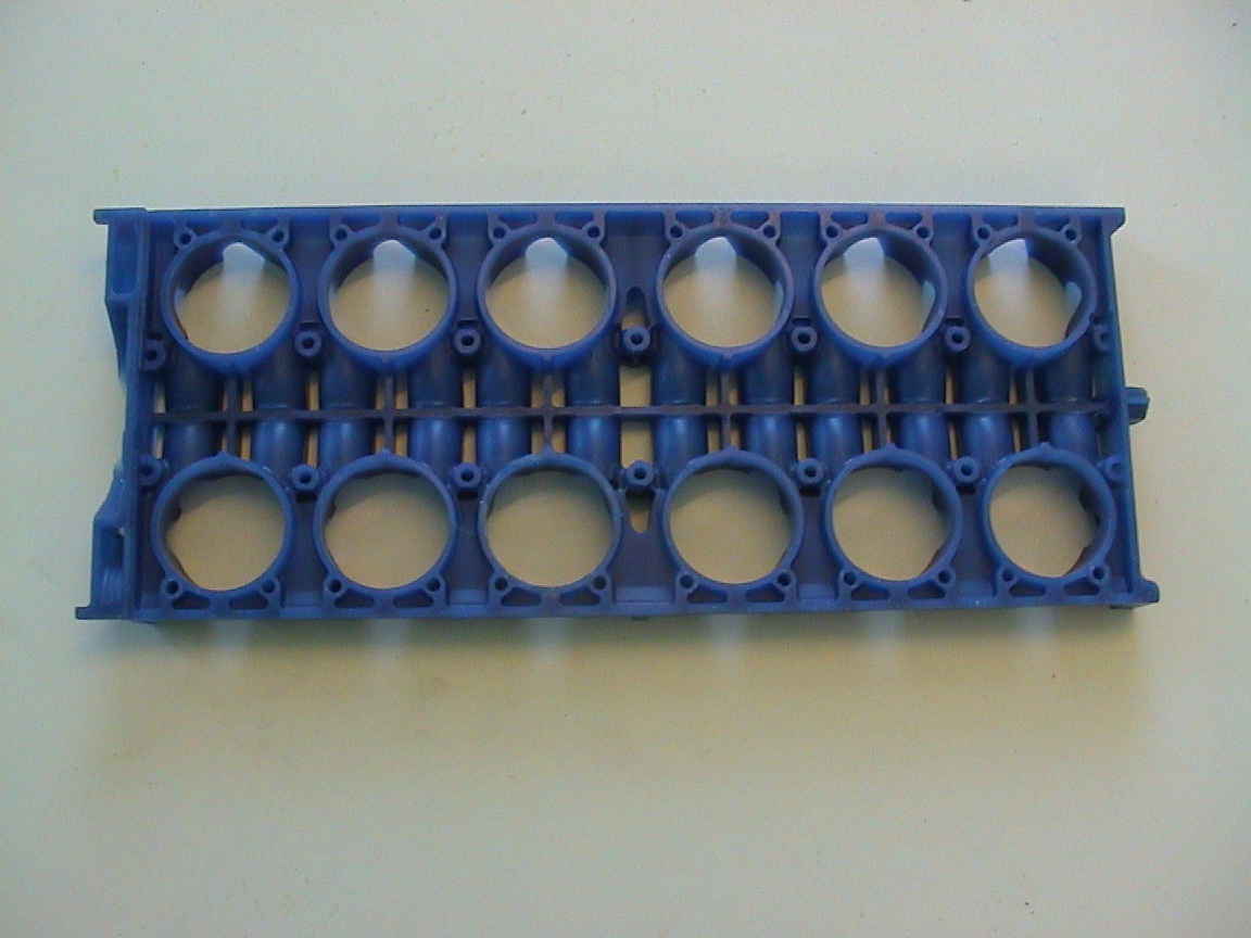
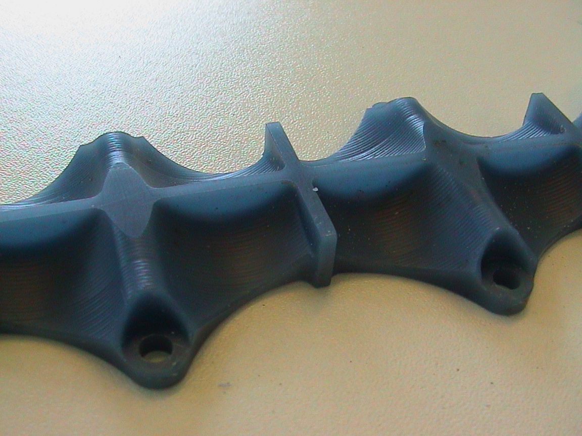
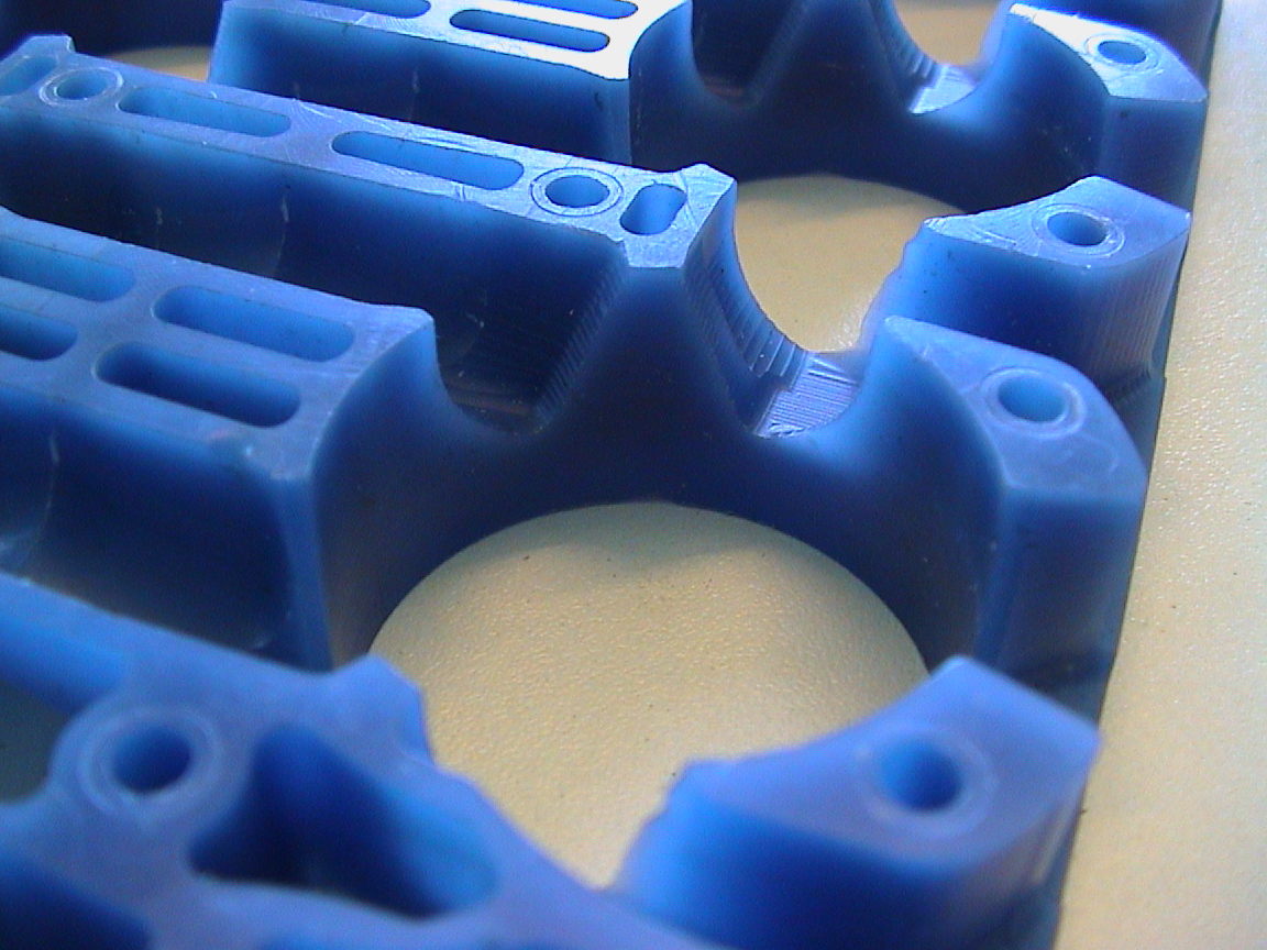
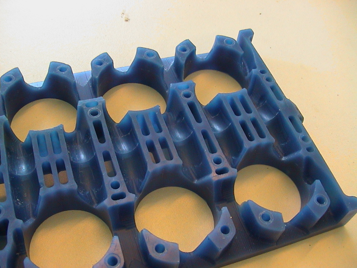
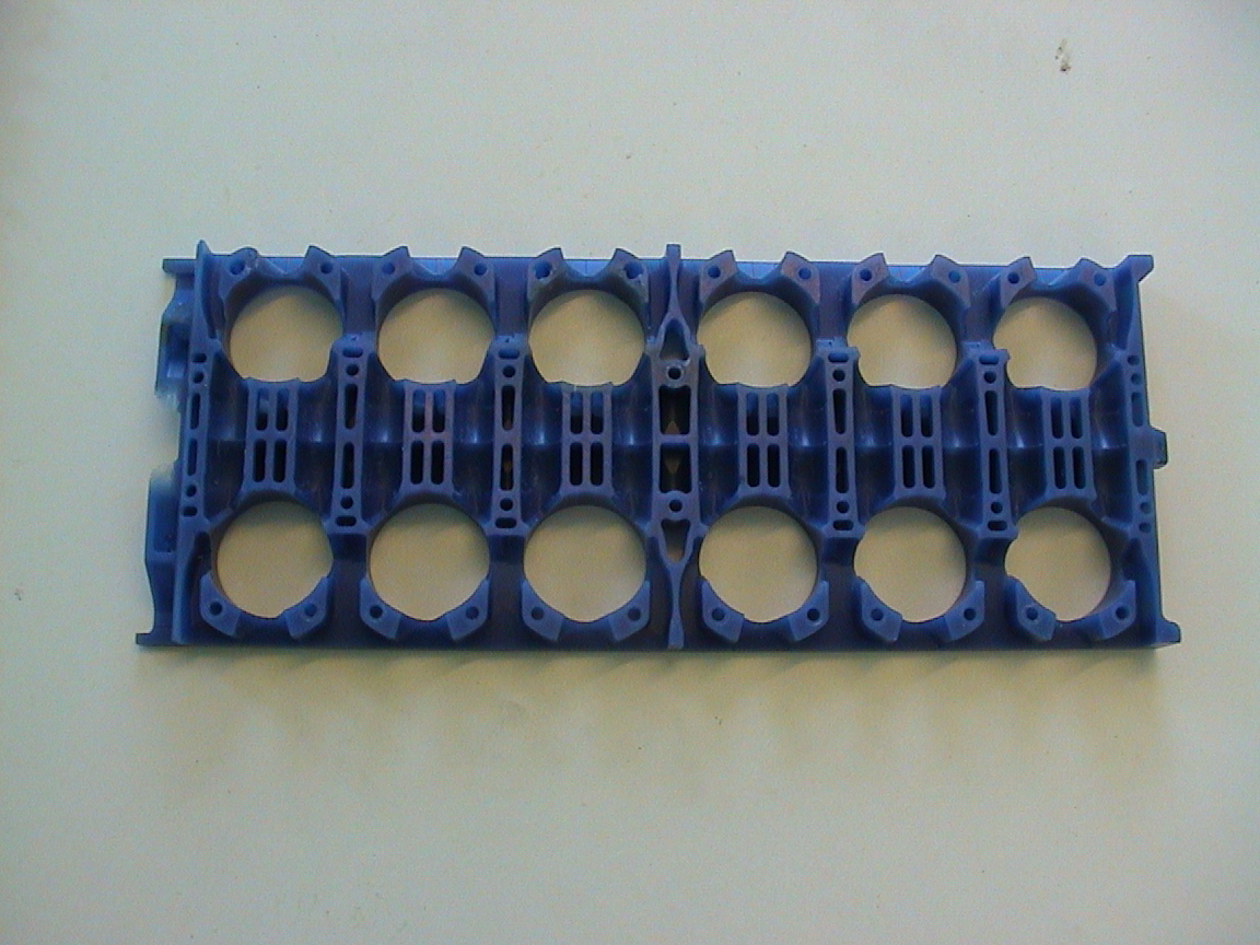
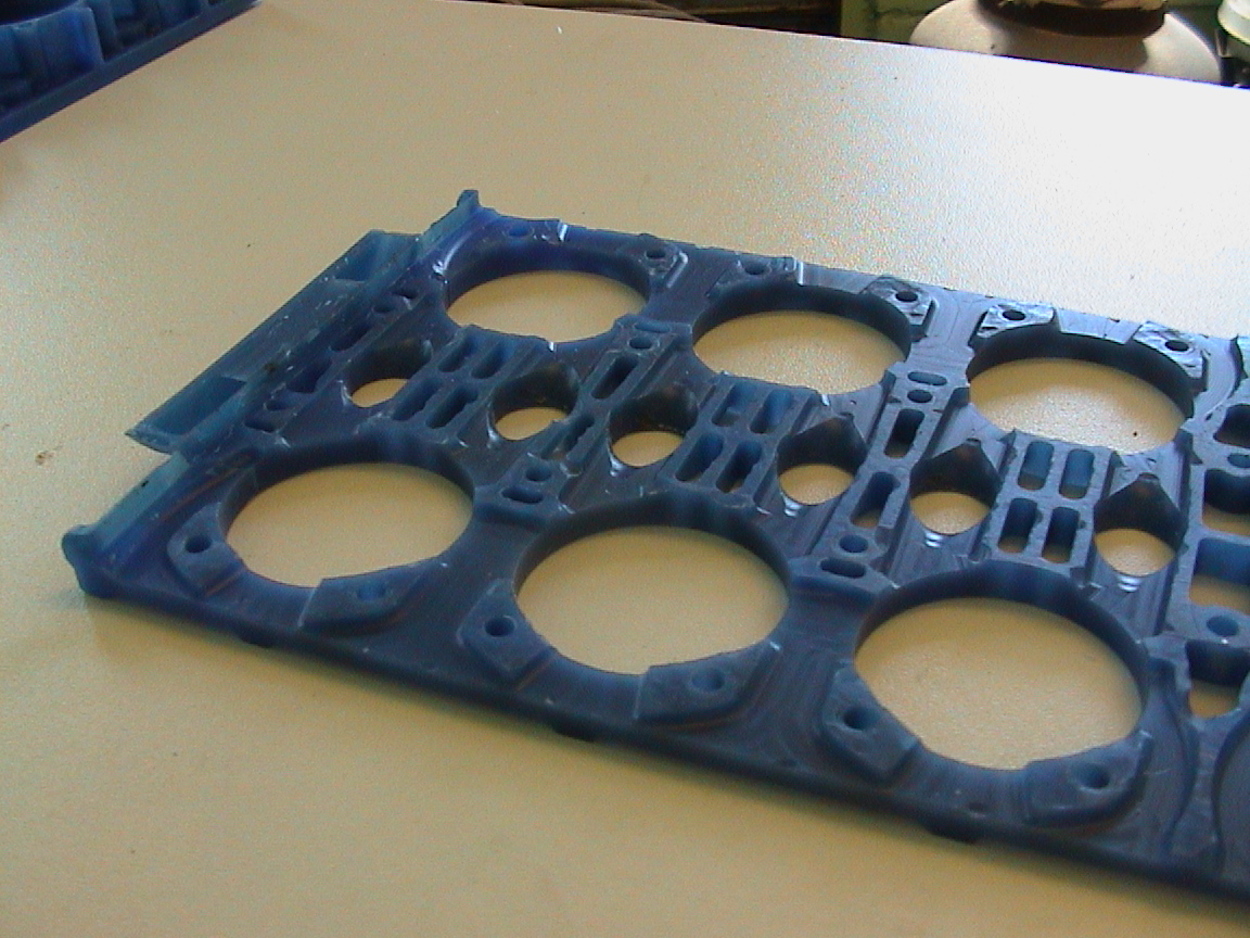
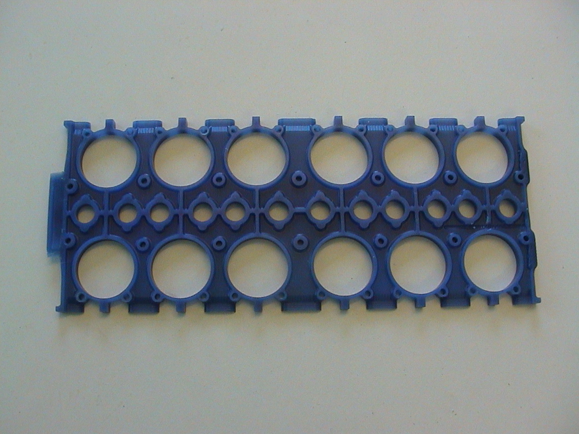
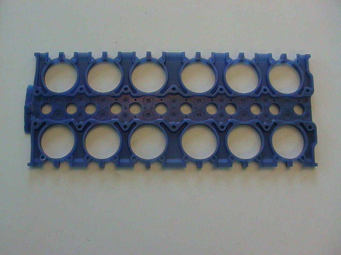
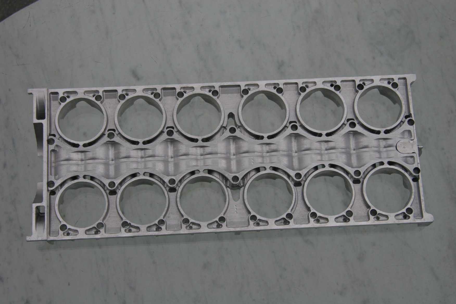
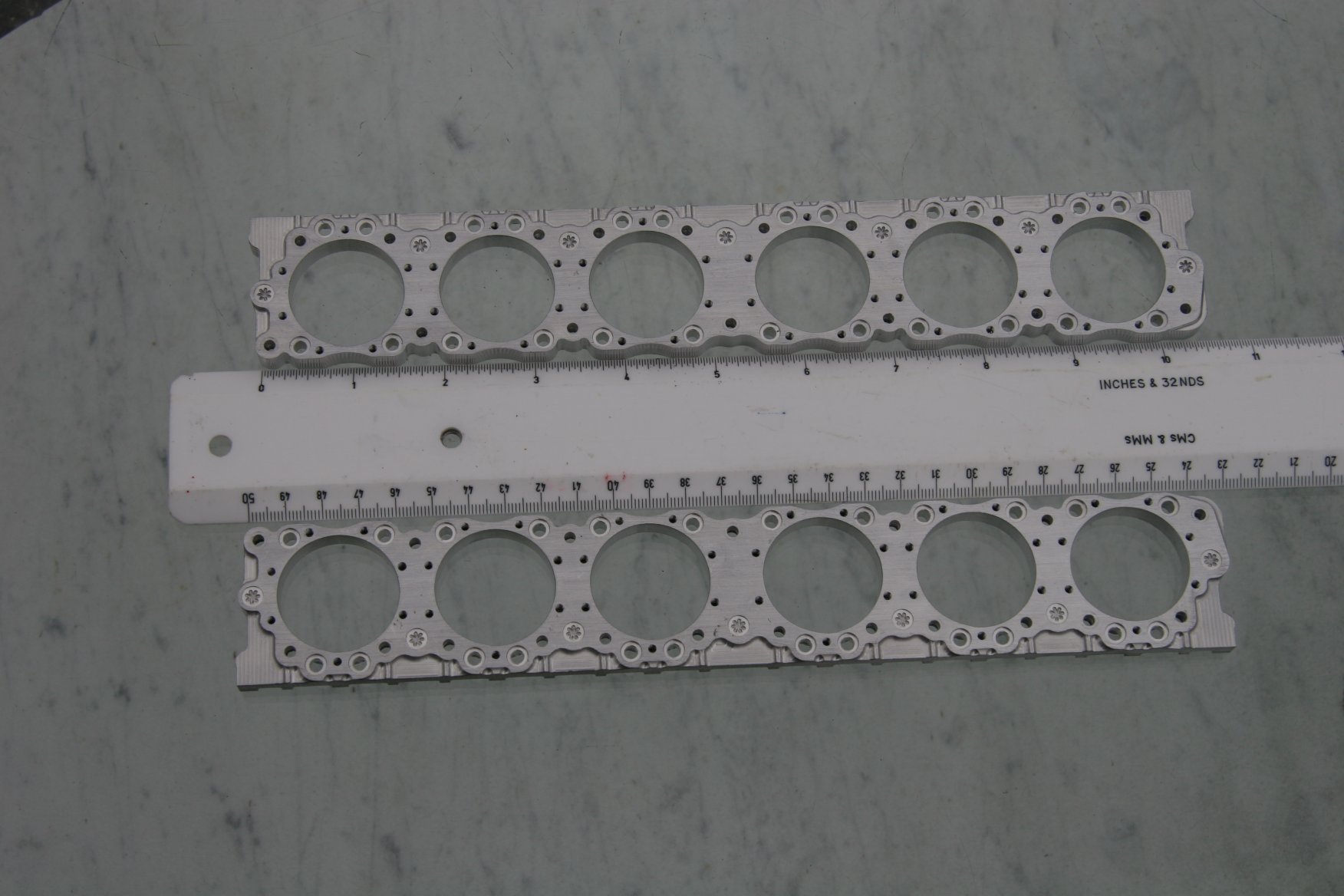
Full-size Napier Sabre cylinder blocks were machined from intricate castings. For his quarter-scale model of the Sabre, Tomlinson came up with an ingenious scheme to build up the cylinder blocks from five separately machined "plates" and an insert. This sandwich of cylinder block plates will be bonded together, finished machined, and then the bores sleeved with ported aluminum sleeves. There are 38 hollow dowel bolts securing the assembly. The dowel bolts have an outside diameter of 5.0mm and an inside diameter of 3.0mm. They pass from the inner face of the inner plate through reamed holes in the inner four plates and are threaded into the inner face of the outer plates. These bolts have sacrificial hex heads and 6.50mm diameter shoulders which fit into 2.50mm deep counterbores in the reamed holes on the inner face of the inner plate. The mating faces of the plates are assembled "metal to metal" and sealed with Aero grade Hylomar. Following assembly the hex heads will be machined off flush with the inner face so there will be no evidence of any fixing. Why 38 bolts and why hollow? Each cylinder block is held to the crankcase by a series of 38 1/2inch bolts! These scale down to approx 3.0mm.
Sabre cylinder blocks are oriented with the bores horizontal. In the following image galleries, the plates are numbered from the crankcase outward. Images of "inner face" views assume the observer is facing away from the crankcase and images of "outer face" views assume the observer is facing the crankcase. Initial plate prototypes were machined from wax.
 |
 |
 |
 |
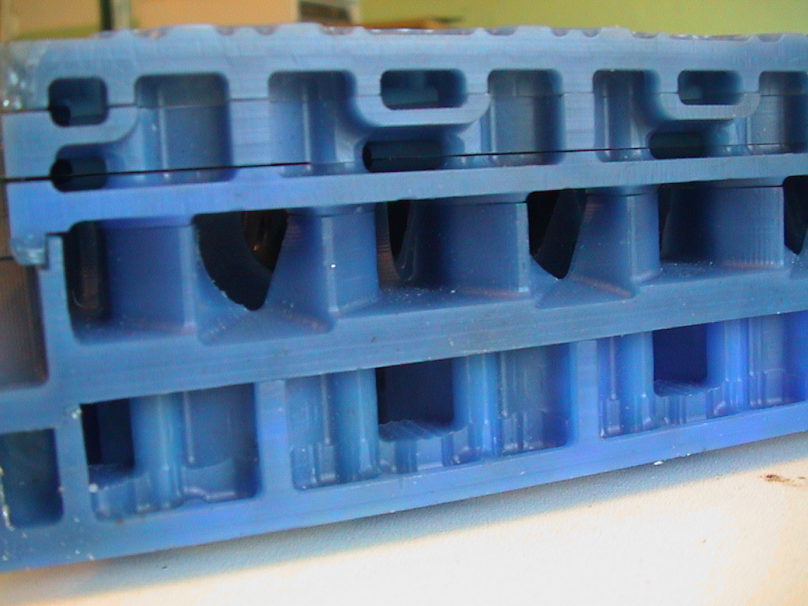 |
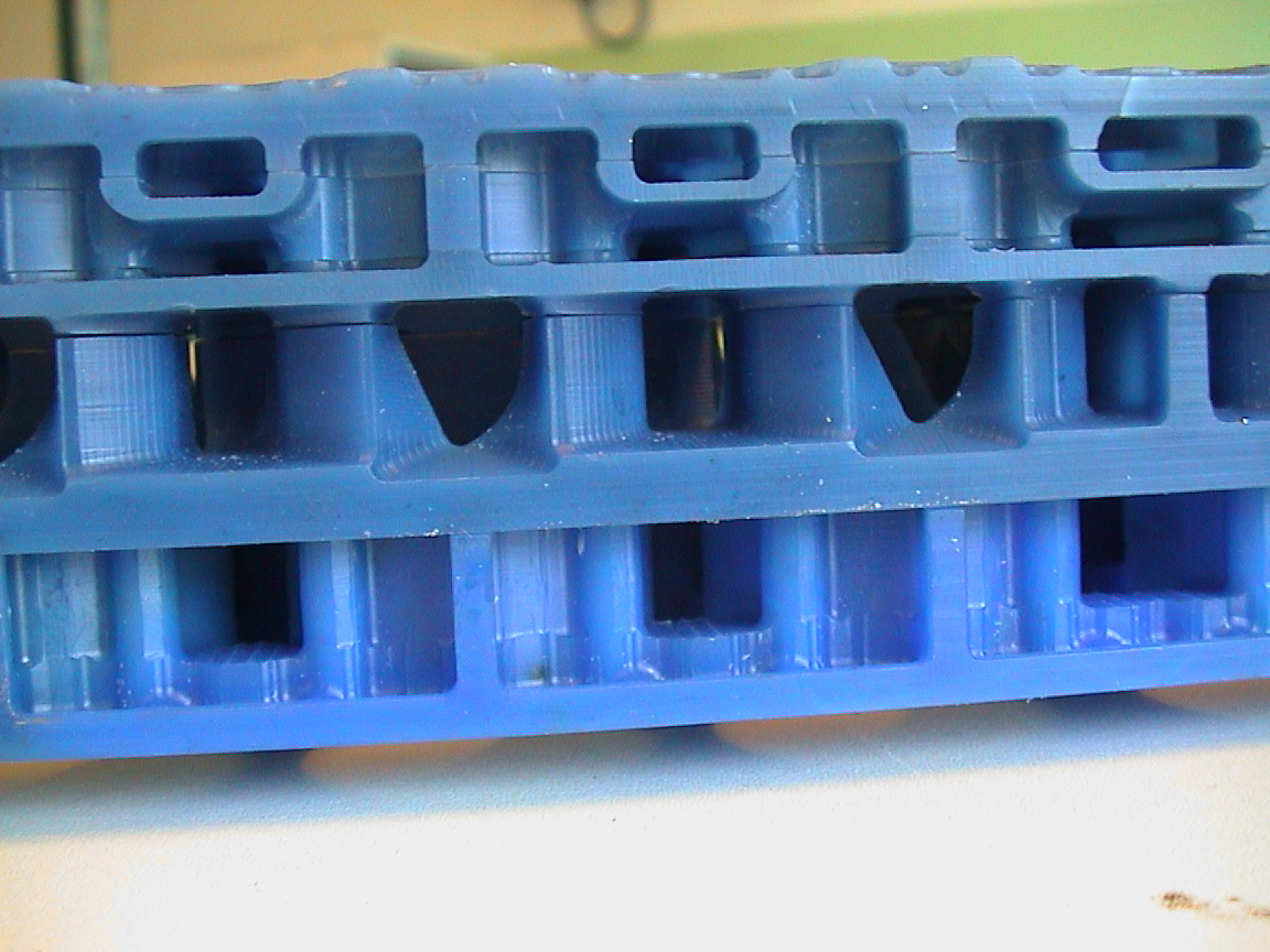
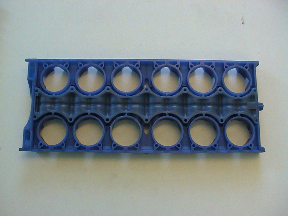
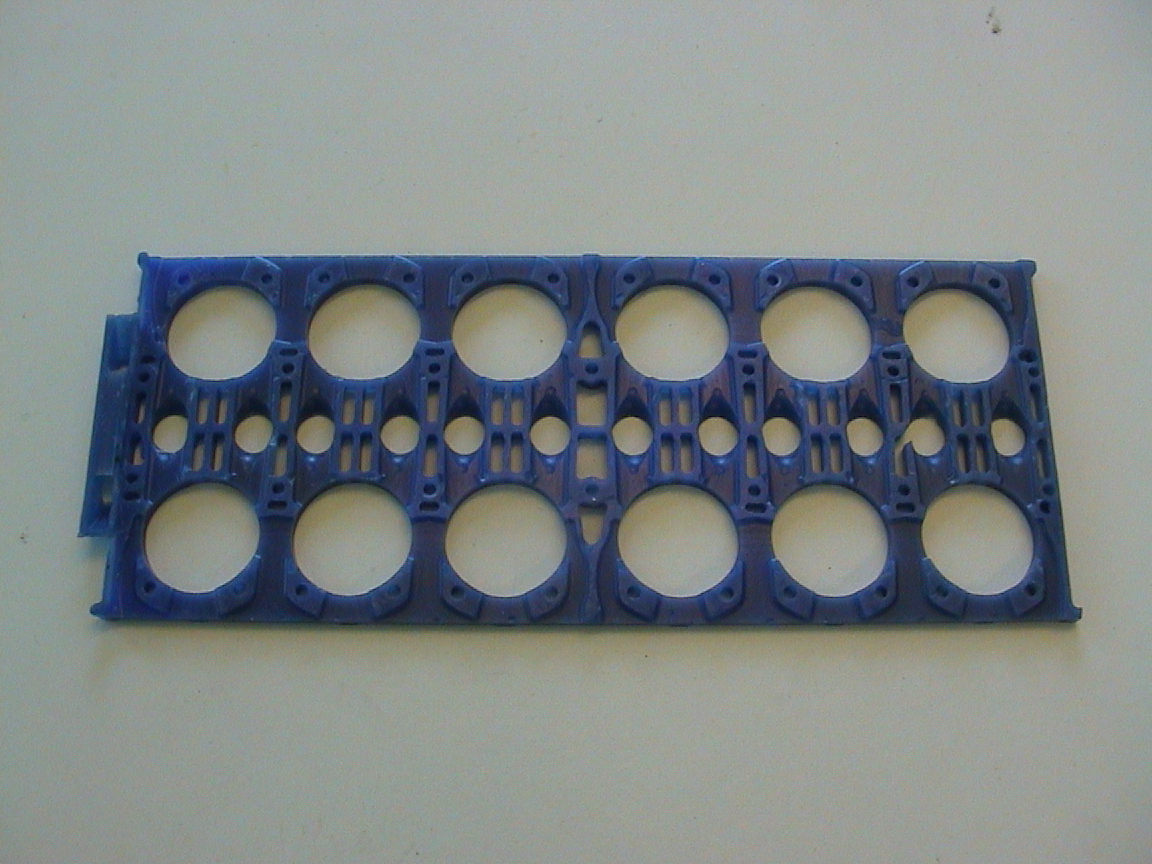
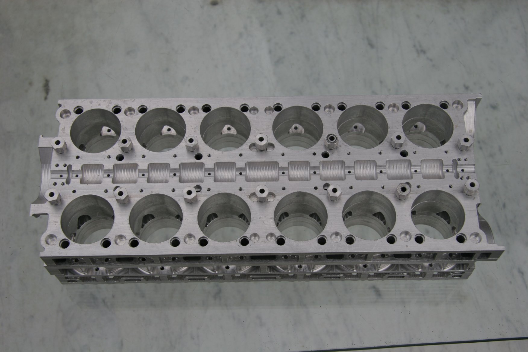
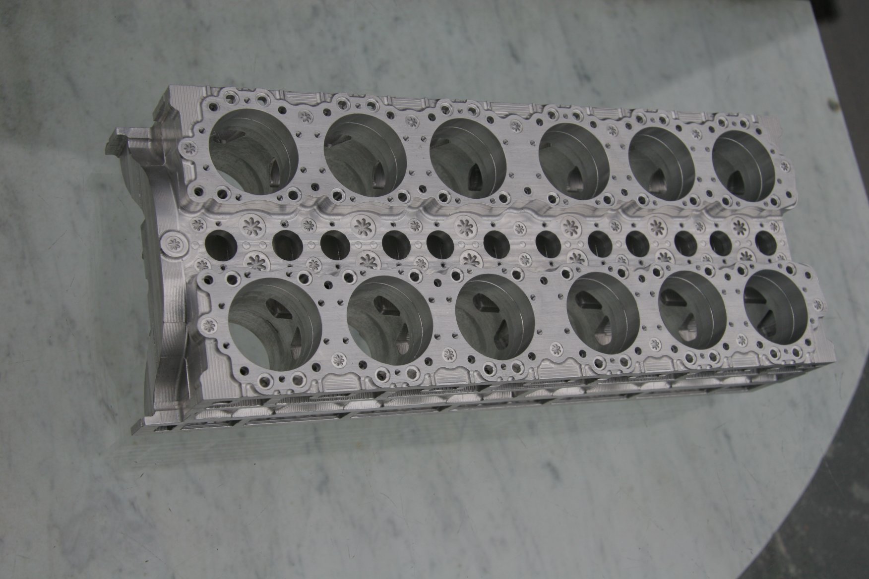
| Cylinder Assembly Front. Plate 1 is on the bottom. Plate 5 is on the top. The "outer face" is at the top. | Cylinder assembly showing exhaust ports (center) that lead to exhaust openings in the front cylinder row. Inlet ports are visible in the rear row. | Cylinder Assembly Rear | Cylinder Assembly Showing Inlet Port Profile (center) | Cylinder assembly with good views of water ways (top and bottom) |
 |
 |
 |
 |
 |
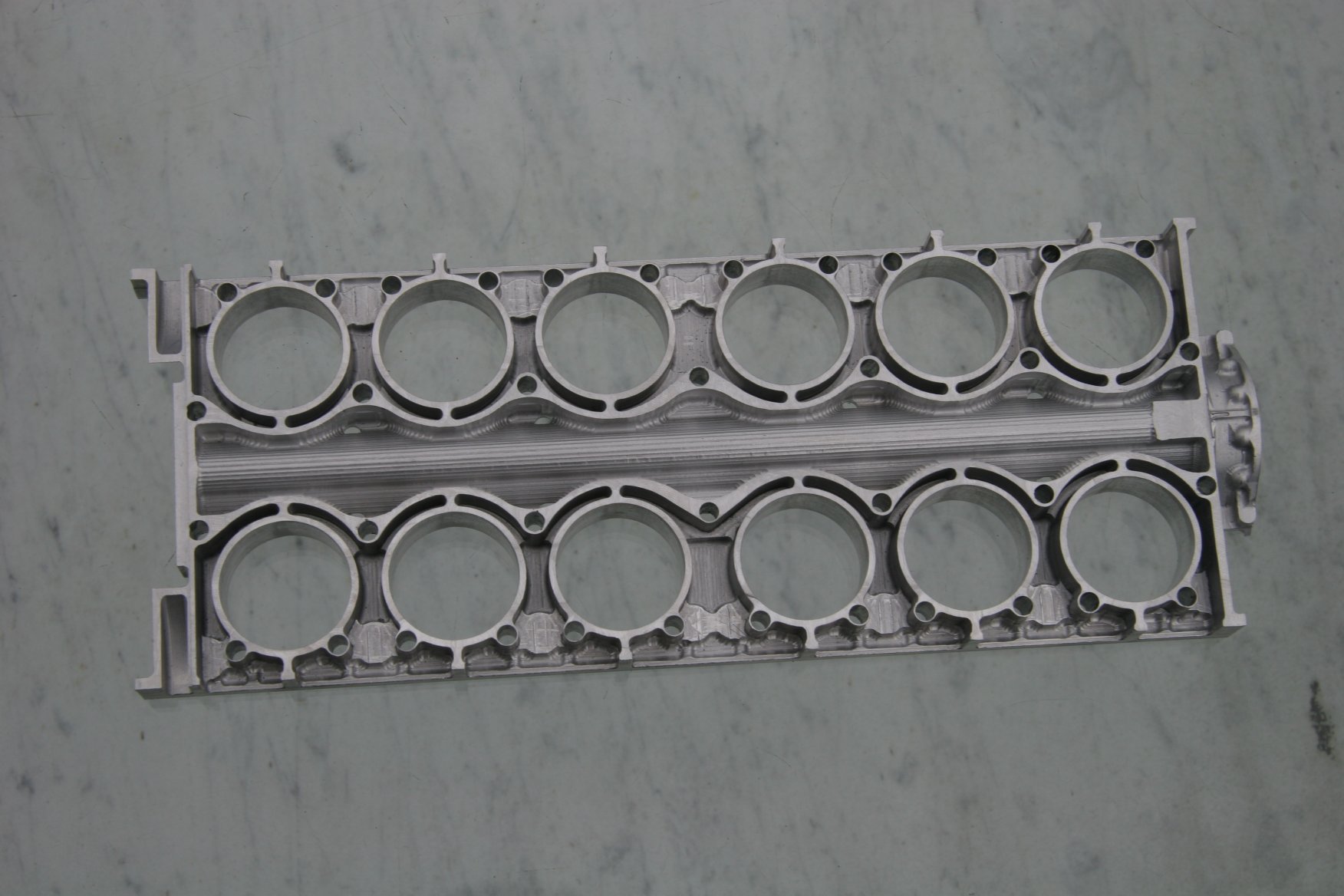
| Plate 1 Inner Front | Plate 1 Inner Rear | Plate 1 Inner Face Showing Cutouts for Sleeve Drive Shaft | Plate 1 Outer Rear Detail | Plate 1 Outer Face Showing Rear Mounting for Supercharger |
 |
 |
 |
 |
 |
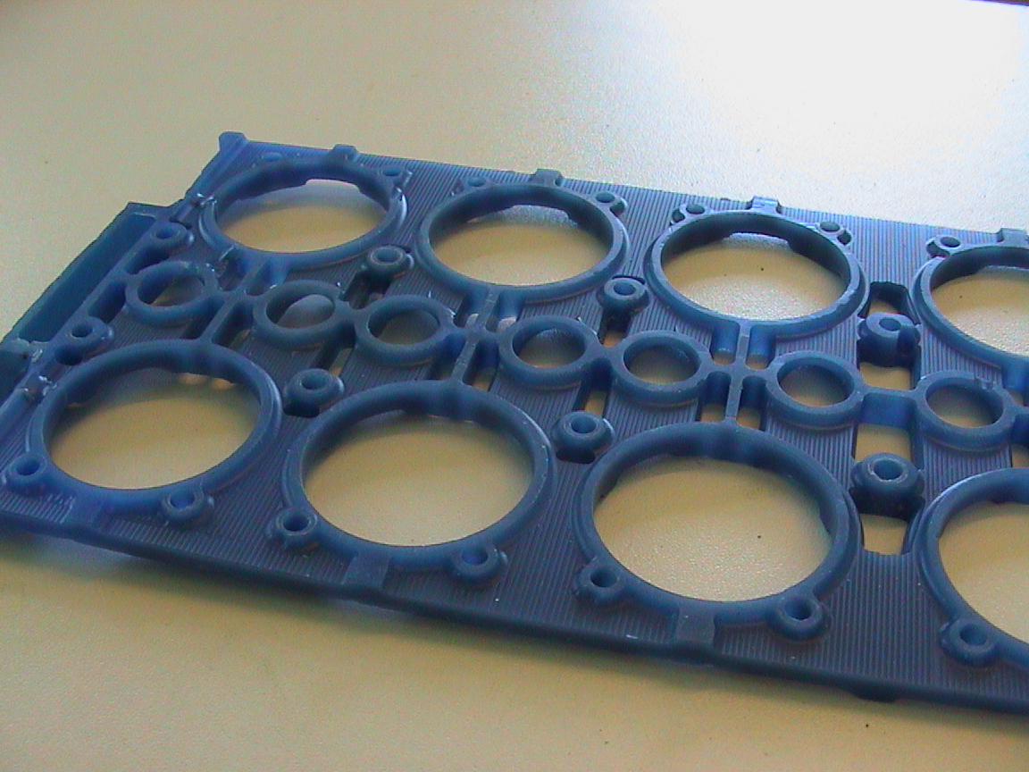
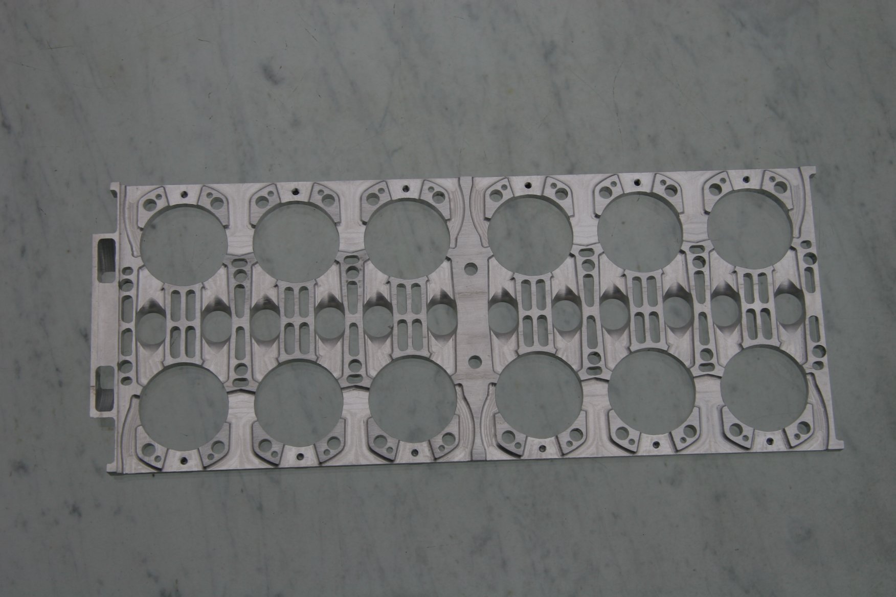
| Plate 2 Inner Front Detail | Plate 2 inner face with insert that forms a boundary between the crankcase (inner face) and cooling water passages (outer face). | Plate 2 inner face less insert showing exhaust gas passages | Plate 2 Inner Face with Insert | Plate 2 Insert Inner Face Detail |
 |
 |
 |
 |
 |
| Plate 2 Insert Outer Face Detail | Plate 2 Outer Face Detail | Plate 2 outer face showing inlet port detail | Plate 2 Outer Face Detail | Plate 2 outer face showing inlet and exhaust ports and passages |
 |
 |
 |
 |
 |
| Plate 3 Inner Front Detail | Plate 3 inner face detail showing top of inlet and exhaust ports and passages | Plate 3 Outer Face Detail | Plate 3 outer face showing top of exhaust ports and passages | Plate 3 Outer Face |
 |
 |
 |
 |
 |
| Plate 3 Inner Face Close Up | Plate 4 inner face detail | Plate 4 Inner Face | Plate 4 Outer Face Close Up | Plate 4 outer face showing water passages, exhaust ports and dummy core plugs. |
|
|
|
|
|
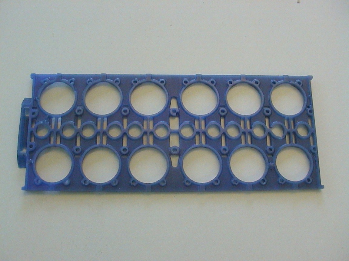
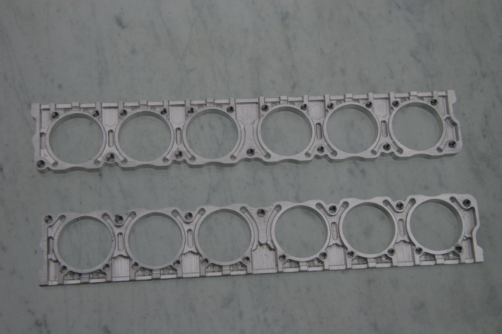
| Plates 5 inner faces showing water passages | Plates 5 inner faces | Plates 5 Outer Face Details | Plates 5 outer face showing o-ring recesses | Plates 5 Outer Faces |
 |
 |
 |
 |
 |
| Cylinder Assemblies | Cylinder Assembly Inner Face | Cylinder Assembly Outer Face | Plate 1 Outer Face | Plate 2 Inner Face plus Insert |
 |
 |
 |
 |
 |
| Plate 2 Inner Face with Insert Installed | Plate 2 Outer Face | Plate 3 Inner Face | Plate 3 Outer Face | Plate 4 Inner Face |
 |
 |
 |
||
| Plate 4 Outer Face | Plates 5 Inner Face | Plates 5 Outer Face with Scale |
Mr. Tomlinson Comments:
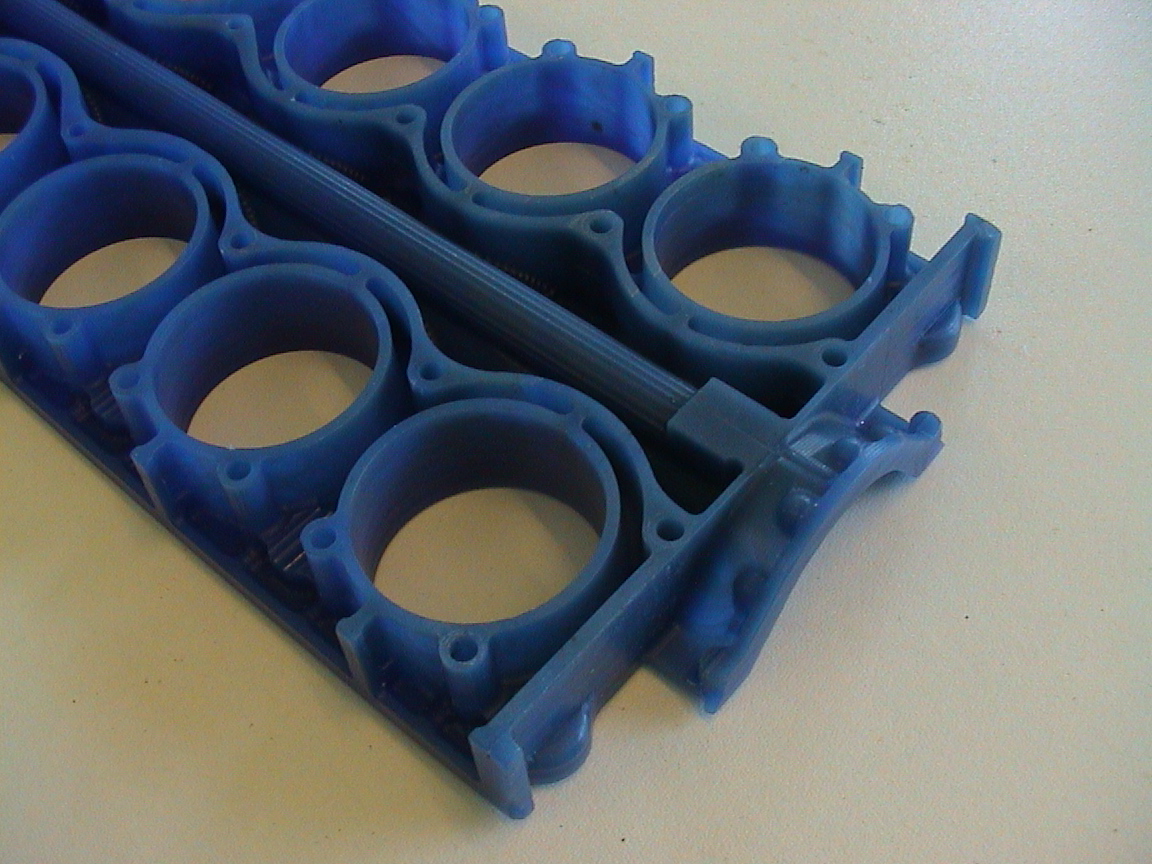
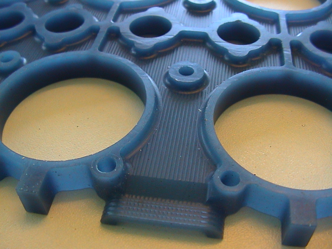
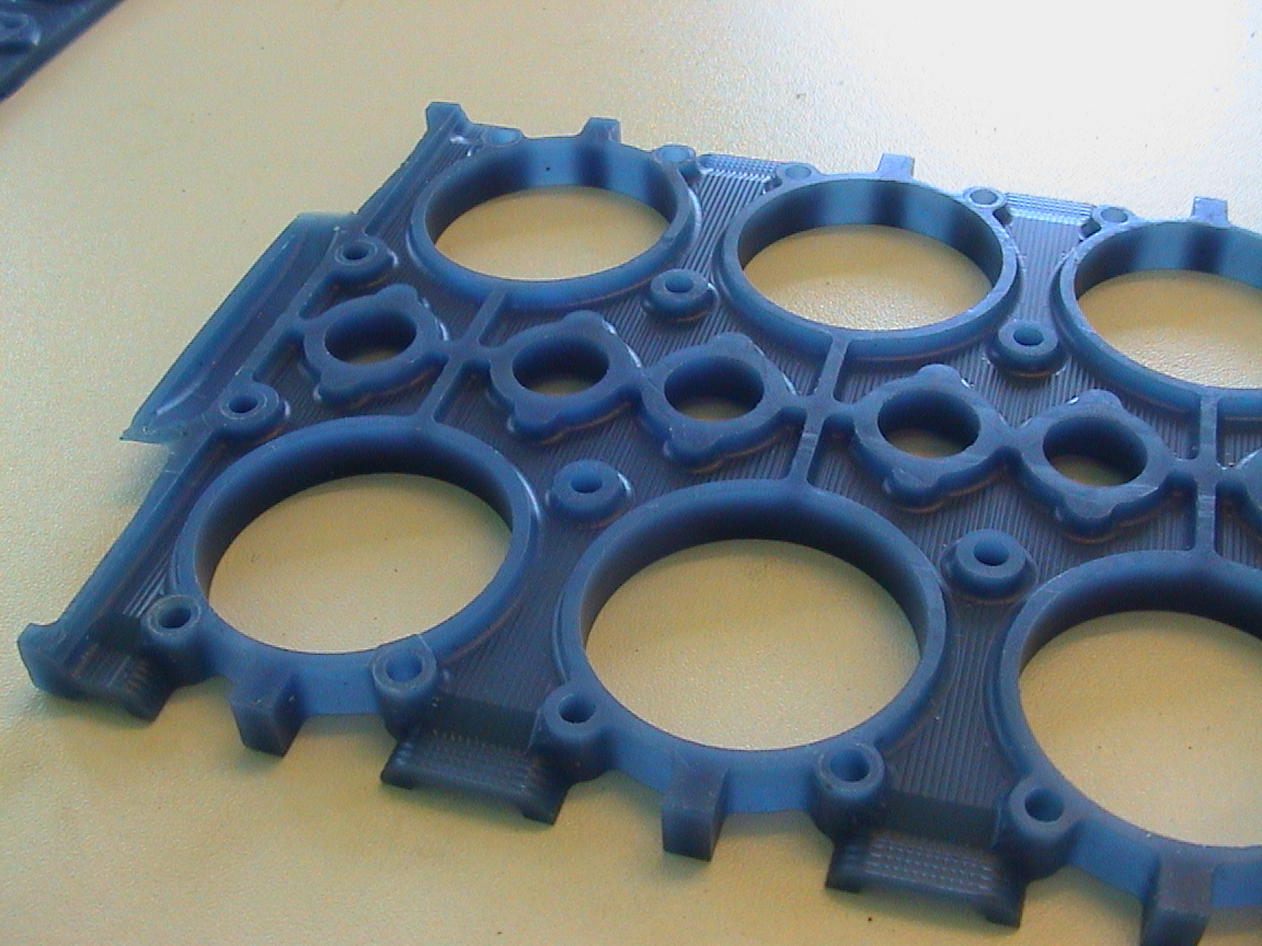
The insert plates are to facilitate the machining of a wall that separates the crankcase space from the cooling water within the block. It was not possible to position the dividing points between the five plates with totally flat surfaces. Some plates are stepped at the front to allow machining of the water transfer passage. I could not get a single step between the two inner plates. If you look at the outer face of the inner plate, the form running down the centre from front to back is over the low pressure oil gallery and is within the crankcase space. The form at the top and bottom is the cooling water collection and discharge to the manifolds. The inner face of the insert is the outer boundary of the crankcase space and the outer face the inner boundary of the cooling water over the exhaust ports.
The cylinder block assemblies are symmetric and fit either side of the engine. This does mean that the top and bottom are mirror images. Therefore the valve sleeves are handed.
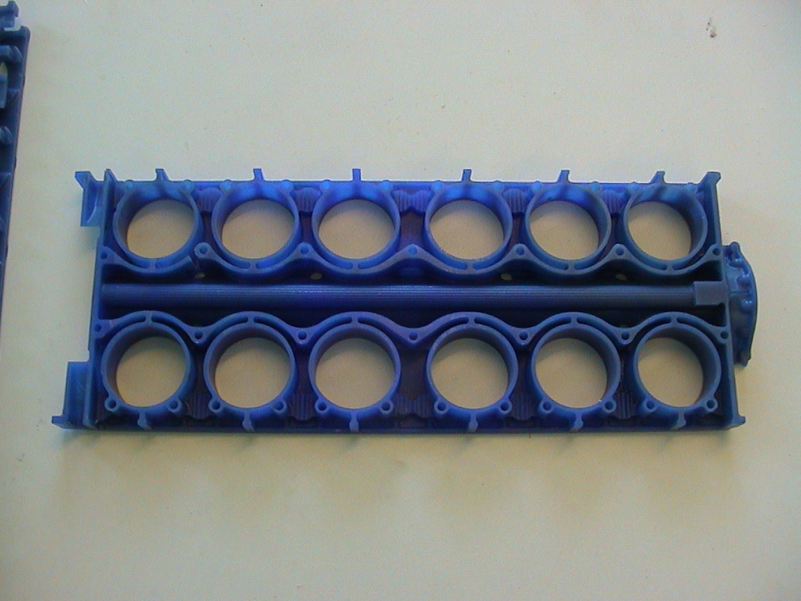
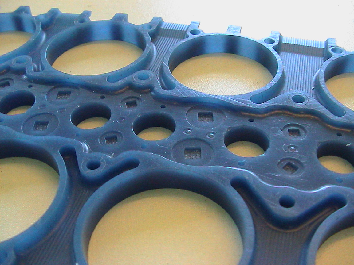
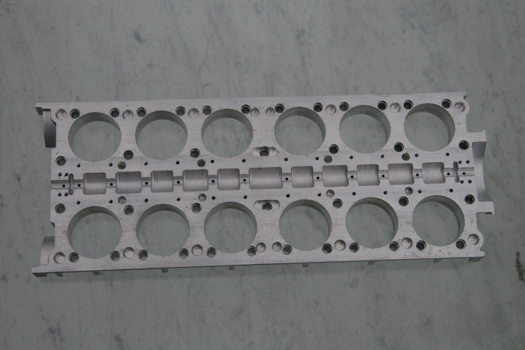
It has taken me a long time to determine the layout of the cooling system within the cylinder blocks in spite of having access to drawings of the Mk2a items. It never fails to amaze me what one uncovers when you get down to the fine detail! I could not make it work satisfactorily. There was a major fault with the design of those early engines. There are separate cooling passages for the top and bottom banks of cylinders in each block. Water enters from the manifolds into the row of seven small rectangular entry ports at the outer side of the top and bottom faces of the blocks. From here it passes around the cylinders above (outwards) the combustion chambers and exits outwards, via drillings, into the top of the top and the bottom of the bottom junk heads. It then re-enters the blocks by drillings from the other side of the heads and emerging into the L-shaped spaces to be seen surrounding the entry ports. These spaces are blanked off by the manifold assemblies. From here the water passes inwards and around the cylinders to collect in the long exit passages at the top and bottom faces at the inner end of the blocks then into the manifolds and to the radiator system.
The trouble is that water is fed to the blocks by two pumps, one under each side of the engine and feeding only into the lower two blocks. How does the water get to the top manifold and therefore the top cylinders? Would you believe it has to pass from the centre inlet port in the bottom face through a transfer port between the two centre cylinders and over the exhaust ports of those centre cylinders to exit into the centre inlet port of the upper half of the block? From there it passes out into the top manifold and back down into the other top ports. The "cooling" water for the top cylinders must have been significantly hotter than that of the bottom.
In the pictures you will notice the seven inlet ports are of differing sizes; the front and rear ones are smaller as they feed a single port into the junk heads. The centre is larger as it has to feed two transfers; one to the head in front and one behind together with the vertical transfer port. The other four feed the heads fore and aft also.The later engines appear to retain the centre vertical transfer passage but have an additional large diameter vertical transfer pipe between the bottom and top manifolds. There also appears to be a series of varying size restrictor plates inserted into the face of the manifolds at the interface with the top and bottom faces of the blocks to balance the flow rates. It is not clear to me yet whether these restrictors are present in the early engines.
Send mail to
![]() with questions or comments about this web site.
with questions or comments about this web site.
![]()