Defective Aircraft Engine Parts, Page 1
by Kimble D. McCutcheon
Published 1 Apr 2017
|
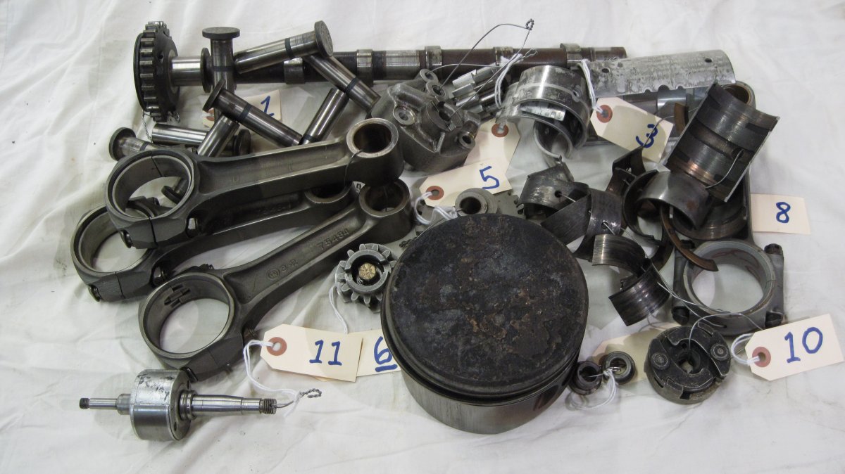
I began collecting examples of defective aircraft engine parts in the 1980s. Recently, the Alabama Aviation Center, Albertville Campus announced it was adding a Powerplant Technology Program to its existing Airframe Technology Program. I decided to the new organization would make a good home for my parts collection. It is my hope that this article's images and narrative, in conjunction with the actual parts, will help students recognize defective engine parts. |
Contents
Exhibit 1 – Worn Camshaft and Spalled Tappets
Exhibit 2 – Lycoming Oil Pump Components
Exhibit 3 – Main Bearing Shell Fretting
Exhibit 4 – Overheated Connecting Rod
Exhibit 5 – Pitted Crankshaft Idler Gear Teeth
Exhibit 6 – Pitted Crankshaft Gear Teeth
Exhibit 7 – Stuck and Broken Piston Rings
Exhibit 8 – Worn Bearings and Defective Connecting Rod
Exhibit 9 – Bendix Magneto Drive Shaft Bushings
Exhibit 10 – Bendix/TCM Magneto Riveted Impulse Coupling
Exhibit 11 – Eisemann Magneto Rotating Magnet
Exhibit 1 – Worn Camshaft and Spalled Tappets
Exhibit 2 – Lycoming Oil Pump Components
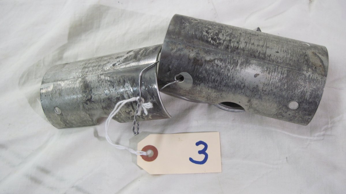
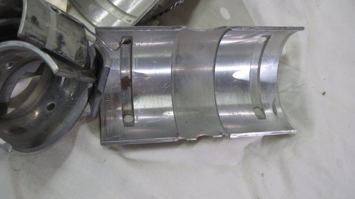
Exhibit 3 – Main Bearing Shell Fretting
ASM International, previously the American Society for Metals, defines fretting as "A special wear process that occurs at the contact area between two materials under load and subject to minute relative motion by vibration or some other force." These Lycoming IO-360-A1A main bearing shells exhibit fretting on their outer surfaces. This was caused by the crankcase being improperly torqued, which did not properly clamp the bearing shells in their crankcase bearing saddles and allowed the bearing shells to move slightly in relation to the saddles. The motion caused polishing and slight metal removal.
 |
 |
 |
 |
| Main Bearing Shell Fretting. Note Polishing on the Bearing Shells. |
Note Bearing Shell Polishing | Note Bearing Shell Polishing. The frosty gray areas are representative of the entire bearing shell surface when it was installed. | Bearing Inside Surfaces. Fretting is also visible on another bearing shell at the top left. |
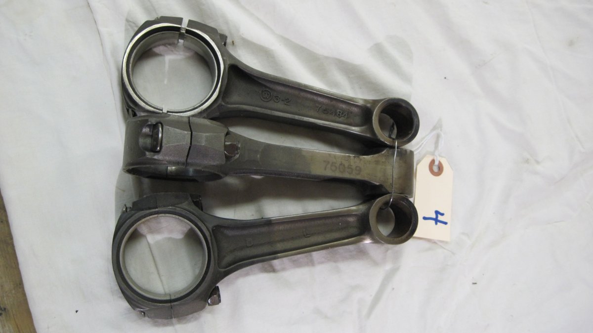
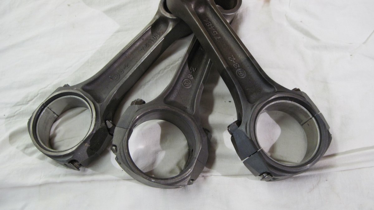
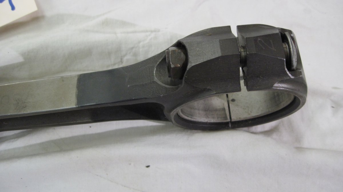
Exhibit 4 – Overheated Connecting Rod
These IO-360-A1A connecting rods were removed at overhaul. The # 2 rod shows signs of overheating, as is evidenced by the discolored big end.
 |
 |
 |
 |
| Three Connecting Rods. Note Discoloration on the # 2 Rod (bottom). |
Discoloration on Right Connecting Rod Big End | Detail of the # 2 Rod Big End | Comparison of Rod Big Ends |
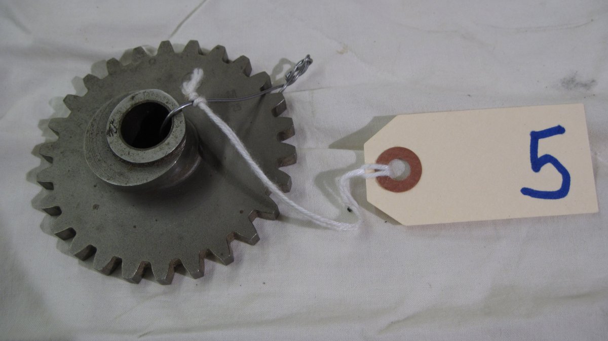
Exhibit 5 – Pitted Crankshaft Idler Gear Teeth
This IO-360-A1A crankshaft idler gear has an eccentric that drives the fuel pump. This gear was removed from service because of pitting at the base of some gear teeth.
 |
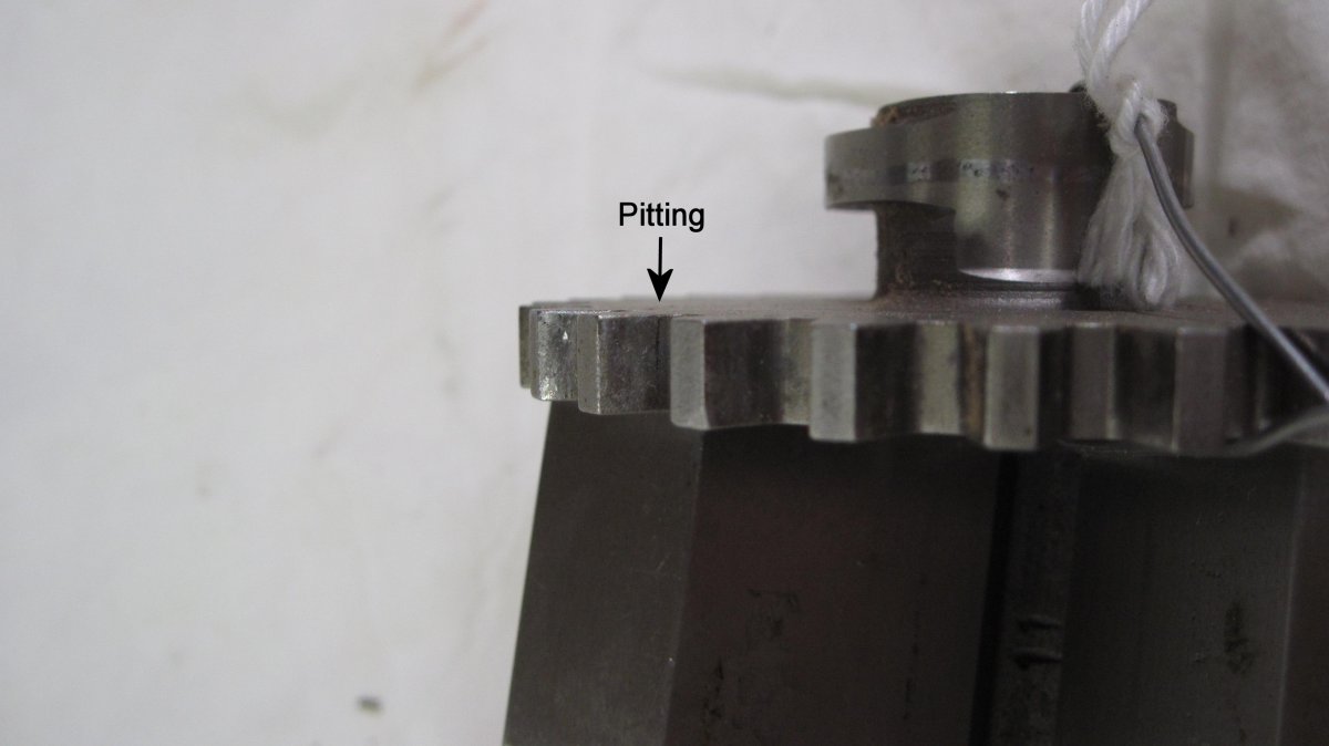 |
| Crankshaft Idler Gear Showing Fuel Pump Drive Eccentric | Pitting on a Tooth Base |
Exhibit 6 – Pitted Crankshaft Gear Teeth
This IO-360-A1A crankshaft gear has several pitted teeth. This gear, and the 5/16-24 bolt that secures it to the crankshaft aft end, is the subject of several FAA Airworthiness Directives (AD 2004-05-24 and 2004-10-14) and Lycoming Service Bulletins/Instructions (SBs 475C and 554, SI 1331). It has to be inspected during overhaul, whenever it is removed, after a propeller strike, and its retaining bolt must be of the proper pedigree.
 |
 |
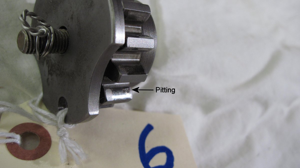 |
| Lycoming Crankshaft Gear | Gear Tooth Pitting | Gear Tooth Pitting. A bit of lock wire keeps the retaining bolt from getting lost from the exhibit. |
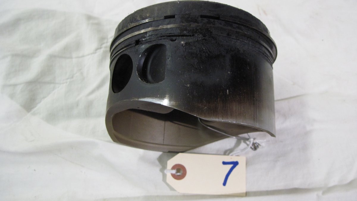
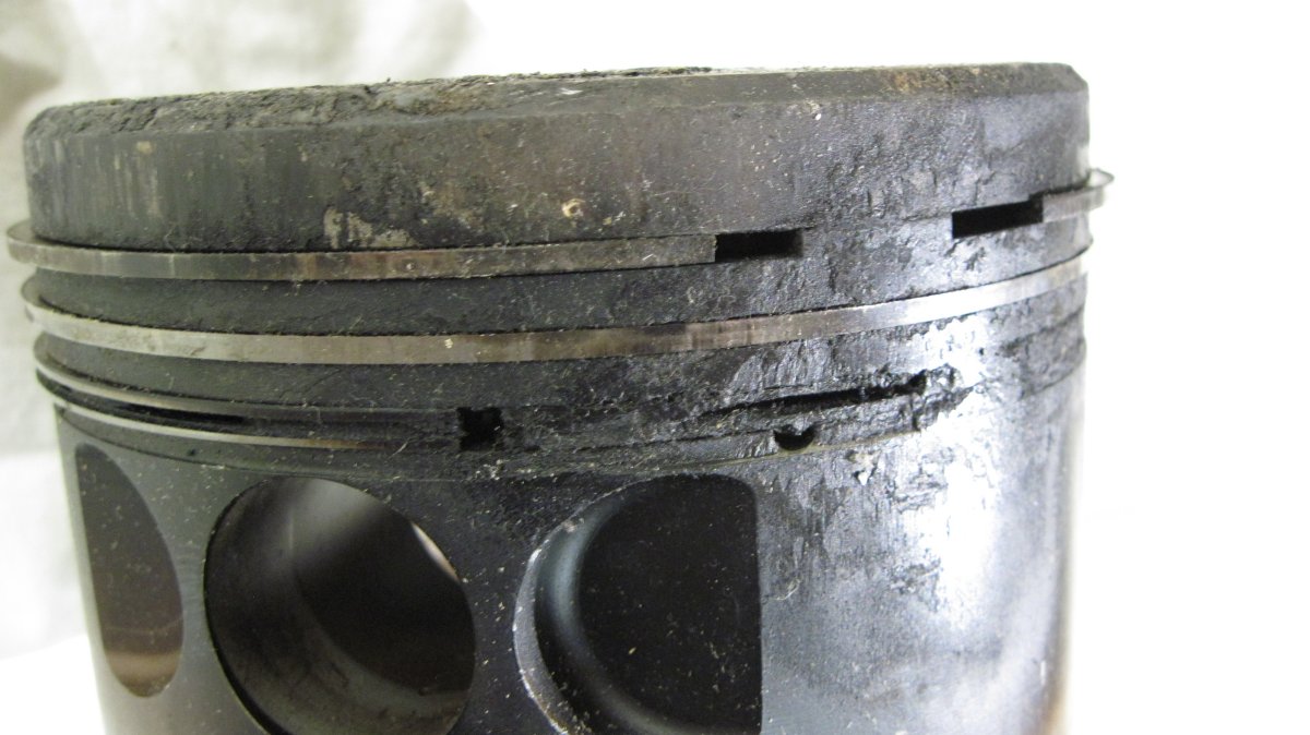
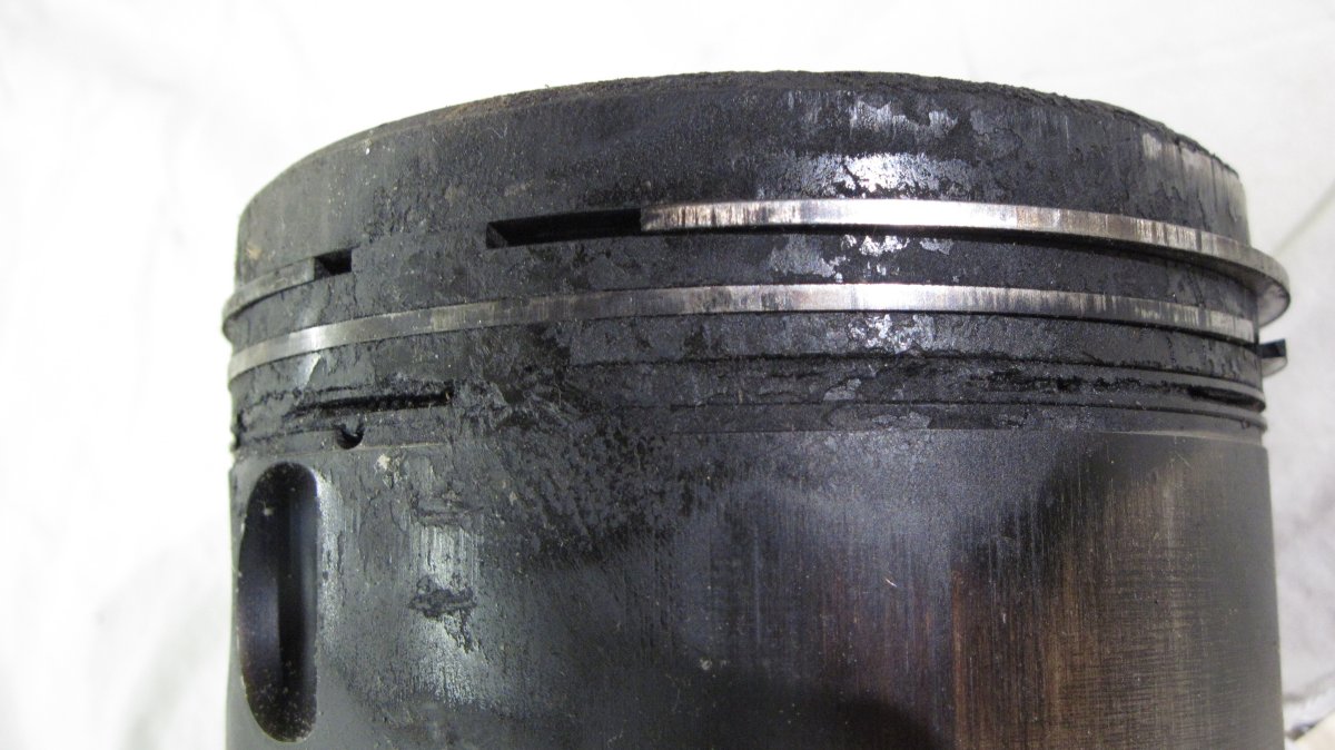
Exhibit 7 – Stuck and Broken Piston Rings
A compression test on this Lycoming O-320 revealed a low cylinder with pressure escaping through the crankcase. When the cylinder and piston was removed, all three rings were stuck and the top one was broken.
 |
 |
 |
 |
| Stuck Rings and Heavy Localized Carbon Accumulation | Another View of the Stuck Rings and Broken Top Ring | Another View of the Stuck Rings and Broken Top Ring | Rings Were Free on the Piston Thrust Side |
Exhibit 8 – Worn Bearings and Defective Connecting Rod
Exhibit 9 – Bendix Magneto Drive Shaft Bushings
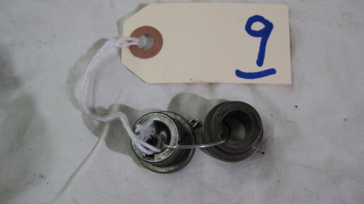
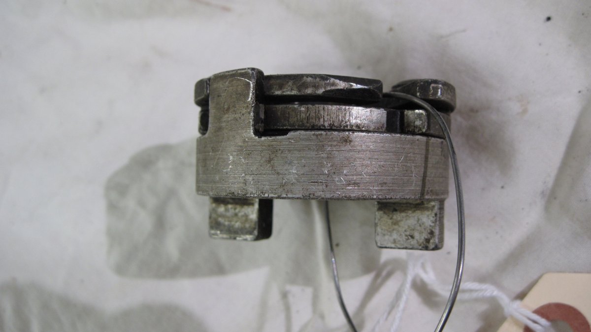
Bendix magnetos with impulse couplings employ a bushing to retain the impulse coupling to the magneto drive shaft. Older drive shaft bushings were made of sintered iron and these bushings had a tendency for the flange to break away. Bendix substituted a machined steel drive shaft bushing that can be identified by an undercut immediately behind the bushing flange; sintered iron bushings did not have this feature.
An FAA Airworthiness Directive, issued 24 Dec 1974, required that the sintered iron bushing be replaced within 200 hours or 90 days, whichever came first. This was to be done in accordance with Bendix Electrical Components Division Service Bulletin No. 556B or subsequent.
Unfortunately, sintered iron bushings continue to show up in Bendix magnetos.
 |
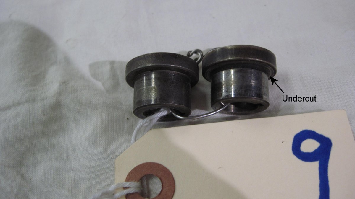 |
| Bendix Magneto Drive Shaft Bushings | Sintered Iron Bushing (left) and Machined Steel Bushing (right) |
Exhibit 10 – Bendix/TCM Magneto Riveted Impulse Coupling
Bendix installed impulse couplings on some of its magnetos to retard spark timing and help with engine starting. Originally these used a riveted flyweight retention scheme, which were subject to wear and failure. In 1978 the FAA issued AD 78-09-07, which established mandatory inspection in accordance with Bendix Service Bulletin 599 at intervals of 1,000 hours. Over the next five years, this AD was revised three times and the inspection interval reduced to 500 hours.
Teledyne Continental Motors (TCM) bought Bendix Electrical Components Division in 1986. In early 1992, TCM changed the impulse coupling flyweight retention means from riveted to snap ring. TCM also changed the flyweight shape to improve its wear characteristics, and marked the new flyweight design with a letter S on both sides of each flyweight nose, which allowed snap ring couplings to be identified while still assembled to the magneto.
On 18 Jul 1996, the FAA issued AD 96-12-07, which superseded AD 78-09-07, retained the inspection interval for riveted impulse couplings at 500 hours, and instituted a 500-hour inspection requirement for snap-ring couplings. This AD also required that the inspections be done in accordance with TCM Mandatory Service Bulletin MSB645, which had superseded Bendix SB599D.
On 19 Jul 2005, the FAA issued AD 2005-12-06, which superseded AD 96-12-07 for Bendix/TCM magnetos installed on Lycoming AEIO-540, HIO-540, IO-540, 0-540, and TIO-540 engines. AD 2005-12-06 required a 100-hour inspection interval for riveted couplings and retained the 500-hour interval for snap-ring couplings.
References
Bendix Service Bulletin No. 599A.
Bendix Service Bulletin No. 599D.
FAA Airworthiness Directive 78-09-07 R3.
FAA Airworthiness Directive 96-12-07.
FAA Airworthiness Directive 2005-12-06.
FAA Special Airworthiness Information Bulletin No. NE-02-32.
Teledyne Continental Ignition Systems Mandatory Service Bulletin MSB645.
 |
 |
 |
| Bendix/TCM Magneto Riveted Impulse Coupling | Impulse Coupling Opposite Side | Impulse Coupling Side |
Exhibit 11 – Eisemann Magneto Rotating Magnet
This rotating magnet was removed from an Eisemann magneto because the magnet is loose on the shaft. AMTs performing magneto maintenance should be aware that pressed-together components can sometimes loosen.
 |
| Eisemann Magneto Rotating Magnet |
Send mail to
![]() with questions or comments about this web site.
with questions or comments about this web site.
![]()