
Defective Aircraft Engine Parts, Page 2
by Kimble D. McCutcheon
Published 1 Apr 2017
Contents
Exhibit 1 – Worn Camshaft and Spalled Tappets
Exhibit 2 – Lycoming Oil Pump Components
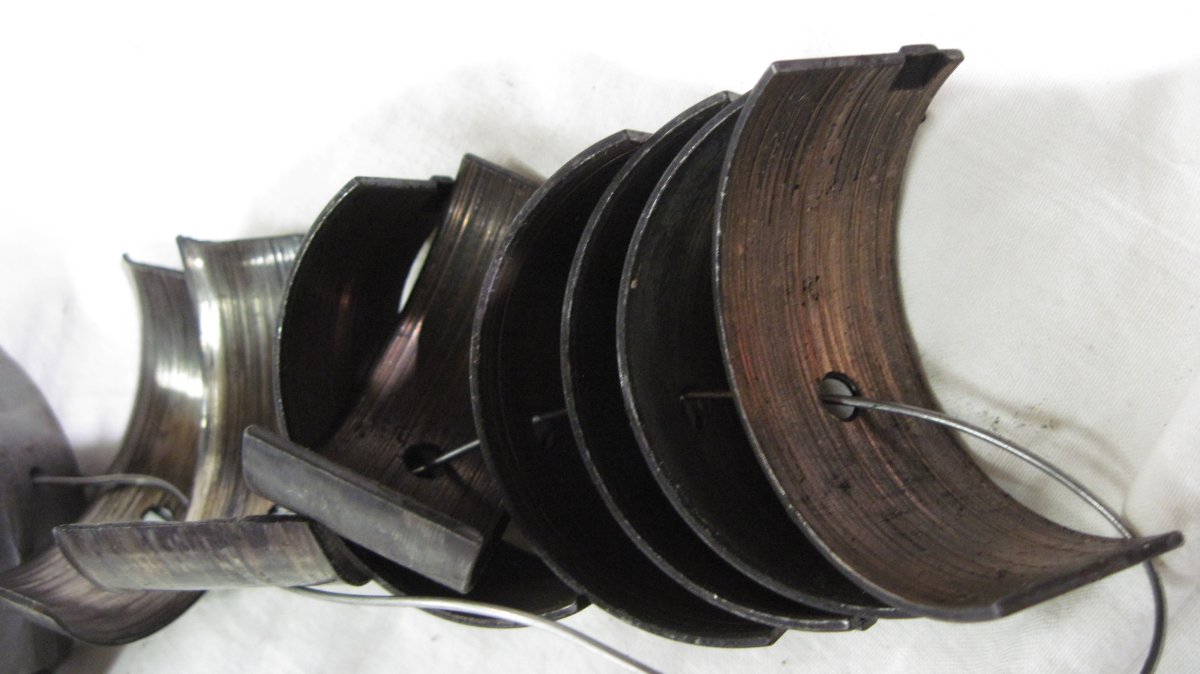
Exhibit 3 – Main Bearing Shell Fretting
Exhibit 4 – Overheated Connecting Rod
Exhibit 5 – Pitted Crankshaft Idler Gear Teeth
Exhibit 6 – Pitted Crankshaft Gear Teeth
Exhibit 7 – Stuck and Broken Piston Rings
Exhibit 8 – Worn Bearings and Defective Connecting Rod
Exhibit 9 – Bendix Magneto Drive Shaft Bushings
Exhibit 10 – Bendix/TCM Magneto Riveted Impulse Coupling
Exhibit 11 – Eisemann Magneto Rotating Magnet
Exhibit 1 – Worn Camshaft and Spalled Tappets
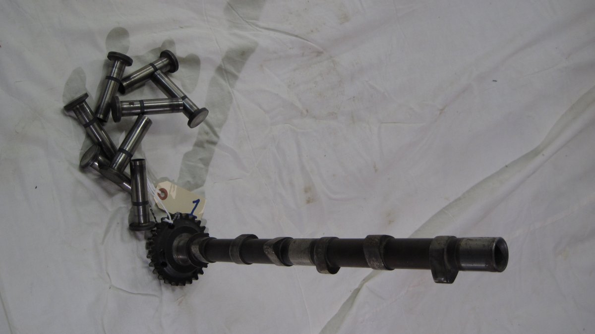
These parts were removed from a Lycoming IO-360-A1A installed in a Mooney M20F.
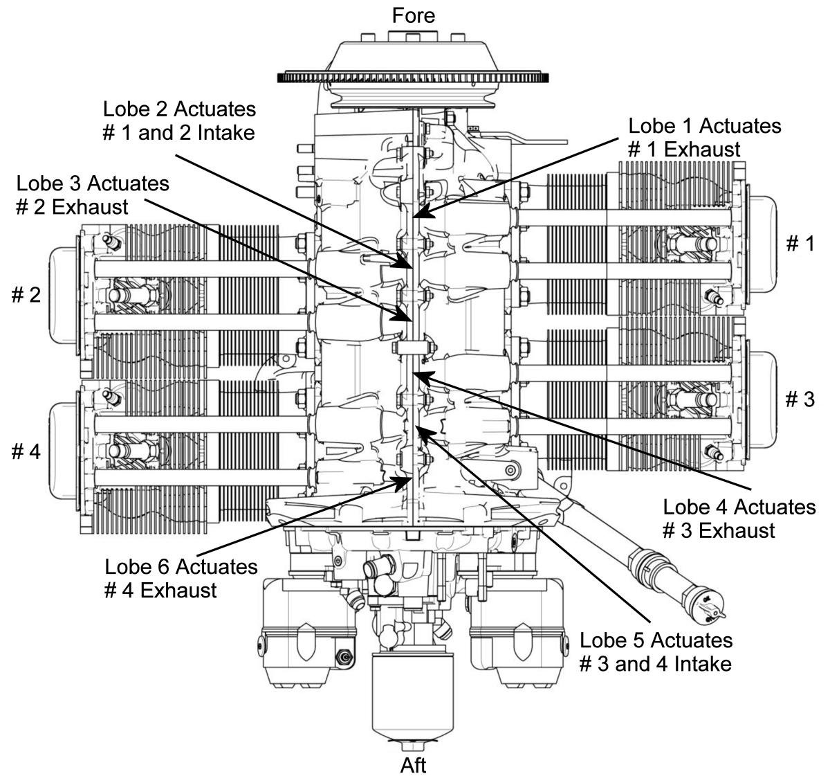
For the purpose of this discussion the camshaft lobes will be numbered starting with the one closest to the propeller and moving aft toward the camshaft gear. Lobe # 1 actuates the cylinder 1 exhaust valve. Lobe # 2 actuates cylinders 1 and 2 intake valves (one lobe serves two cylinders). Lobe # 3 actuates the cylinder 2 exhaust valve. Lobe # 4 actuates the cylinder 3 exhaust valve. Lobe # 5 actuates cylinders 3 and 4 intake valves. Lobe # 6 actuates the cylinder 4 exhaust valve.
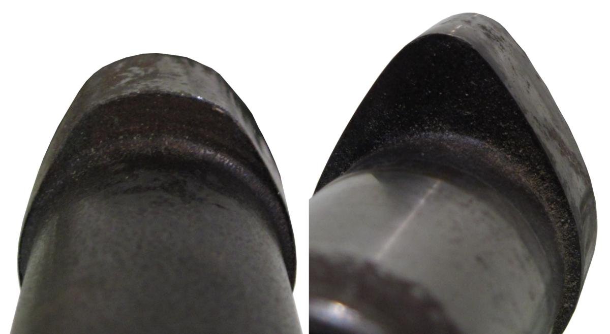
Inspection of the six lobes reveals that four of them are badly worn, the worst (lobe # 5) being worn 0.174", a 51% intake valve lift decrease and a drastic change in valve timing.
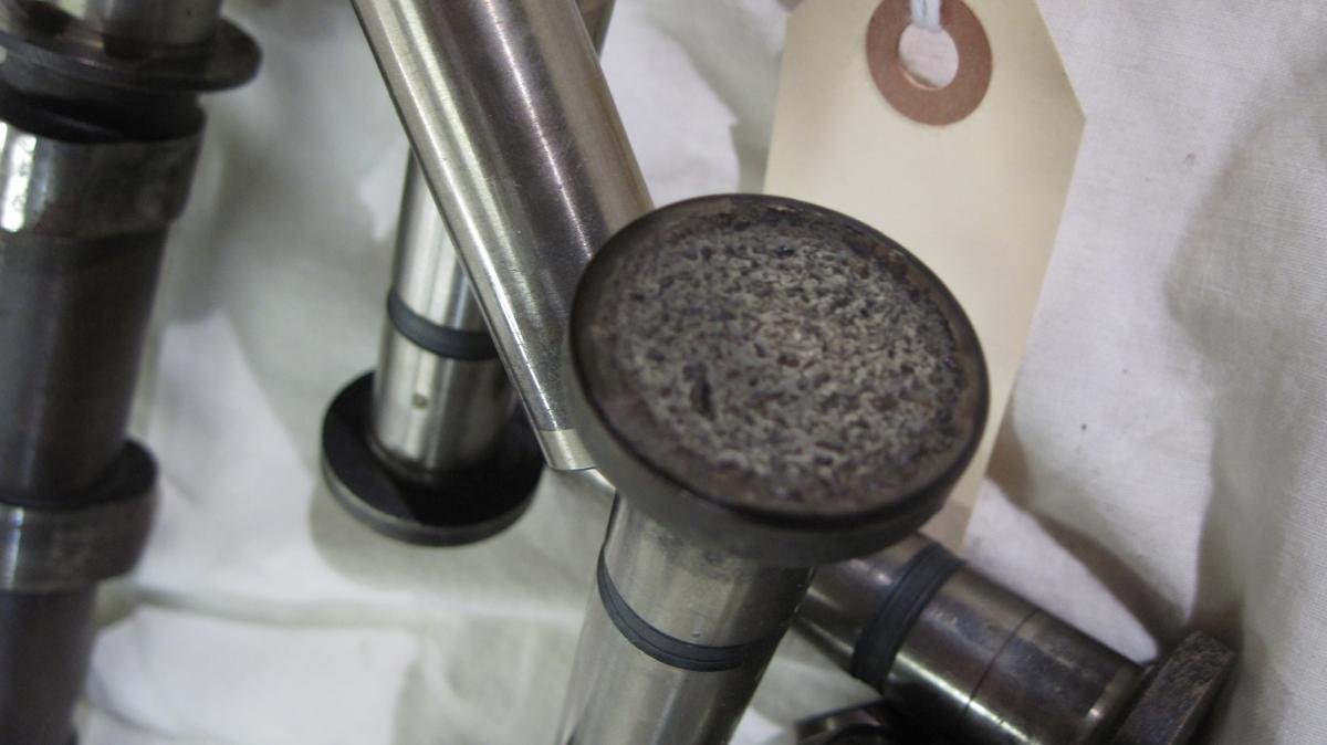
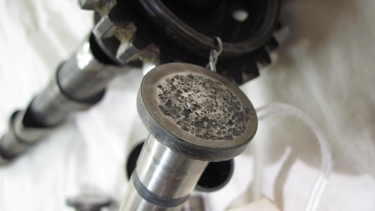
Examination of the tappets reveals that all intake and two exhaust valve tappets show signs of severe spalling, a phenomenon that typically begins with corrosion of the tappet faces. The corrosion weakens and pits the otherwise very hard and smooth tappet and cam surfaces. Eventually the rubbing of the cam on the tappet face starts to break off chunks of metal so large that they are captured by the engine oil system suction screen. These metal chunks look like flakes or fingernail clippings and are attracted by a magnet.
Internal engine corrosion is usually the result of the engine not being flown often enough. If the engine is not flown at least once a week, water vapor, a natural byproduct of hydrocarbon combustion, condenses inside the engine and attacks steel cylinder barrels, piston rings, cams, tappets and gears. Simply running the engine on the ground is not sufficient as internal temperatures do not become high enough to eliminate trapped moisture. Some think ground running is actually worse than not running at all. Another myth is that one can pull the propeller through by hand to keep the cylinder walls lubricated; in truth the opposite happens as piston rings scrape the oil film from the cylinder walls, promoting more rapid corrosion.
Despite this serious internal engine damage, this engine seemed to be running fine. Its magneto check was within limits and it developed full takeoff rpm. But aircraft performance suffered; the takeoff run became progressively longer and rate of climb progressively worse. Clearly the reduced valve lift and altered valve timing was taking its toll.
Engines with fixed-pitch propellers would show this kind of internal degradation by failing to reach their specified static rpm. Engines equipped with constant-speed propellers exhibit no such symptoms because the propeller governor compensates for the weak engine by flattening the propeller pitch and the engine still produces full takeoff rpm. Pilots and AMTs must use a different technique to detect weak engines. Engine magneto checks typically are done at a low enough rpm so that the propeller blades are still at their low-pitch hard stops, i.e., the propeller governor is not yet affecting the propeller pitch and the engine behaves just like one with a fixed-pitch propeller. Each engine/propeller combination will require a certain consistent manifold pressure to reach run-up rpm; pilots and AMTs should remember this value and compare it to the manifold pressure reading at each run-up. If the engine starts requiring higher manifold pressure to reach run-up rpm it is an indication that the engine is not making power and the cause should be investigated.
Some engines are equipped with engine-driven superchargers (as opposed to turbochargers), and these require a modified run-up technique. Before starting the engine, one should note the manifold pressure reading; this is the field barometric pressure. Once the engine is started, if the throttle is opened until the manifold pressure equals field barometric pressure the engine will achieve a certain repeatable rpm. Failure to do so is a sign of a weak engine.
|
|
|
| Worn Camshaft with Spalled Tappets | Lycoming Cylinder and Cam Lobe Numbering | Comparison of #1 and #5 Cam Lobes |
|
|
|
| Only two exhaust tappets were not spalled. | Spalled Tappet | Spalled Tappet |
Exhibit 2 – Lycoming Oil Pump Components
These images highlight Lycoming oil pump components that are acceptable and ones that are not. Although the subject of numerous Lycoming Service Instructions and Directives, and also three Airworthiness Directives, incorrect parts are still being discovered in Lycoming engines.
Background
Lycoming oil pumps consist of spur-type impeller gears located within an oil pump body that is bolted inside the accessory housing. Depending on model, the pump is either driven directly by the crankshaft or indirectly by the accessory section gear train.
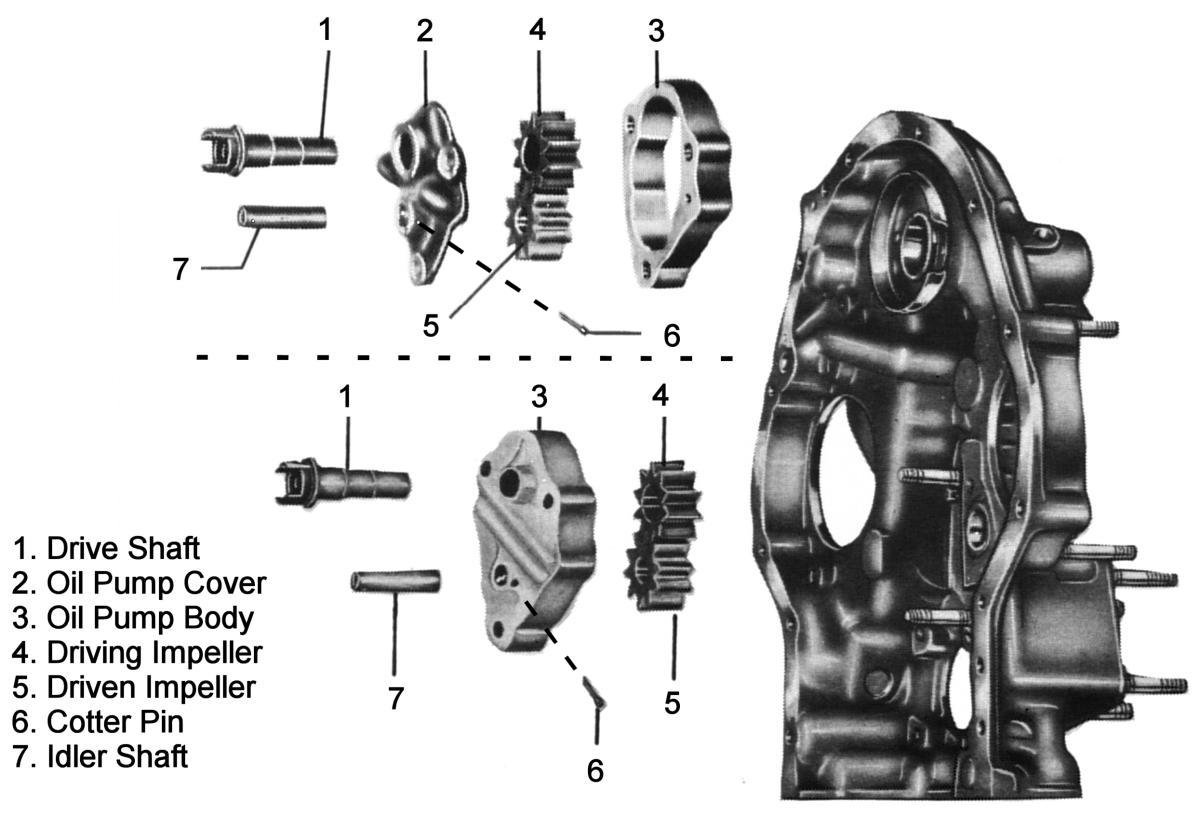
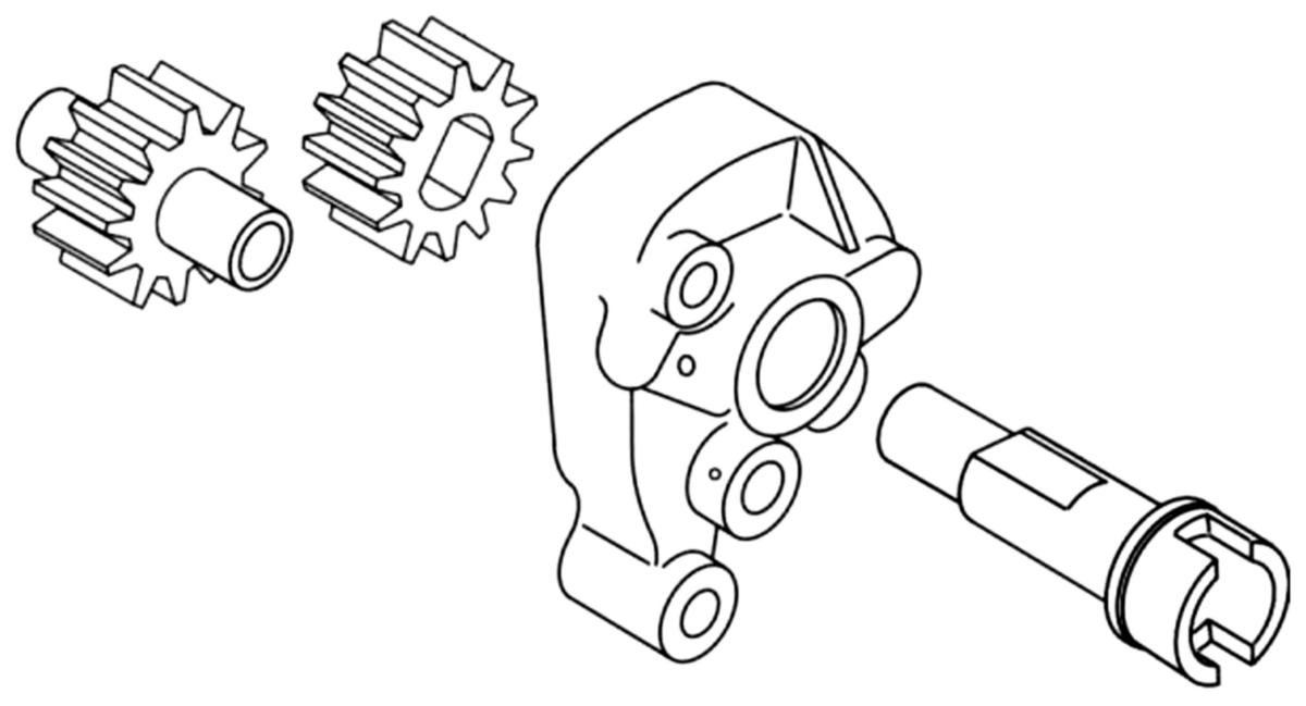
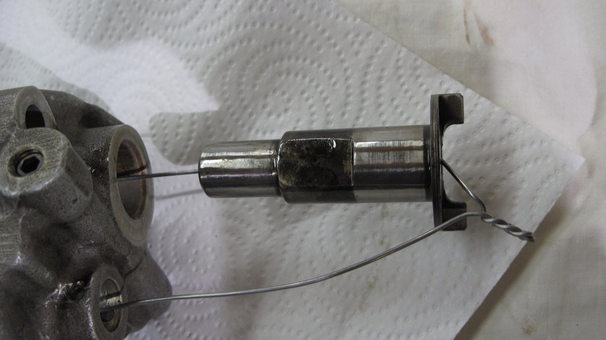
For decades, Lycoming impellers consisted of a steel driving impeller with a double-D hole through it. This mated with an oil pump drive shaft with a matching double-D formed by machining two flats into opposite sides of the shaft. The other half of the pump was an aluminum driven impeller, which ran on a hollow steel idler shaft captured by the oil pump body and accessory housing. The idler shaft was lightly pressed into the oil pump body and retained from rotation by a cotter pin passing through cross-drilled holes in the shaft and oil pump body.
By all accounts, this oil pump construction worked well and is, in fact, still used in some older Lycoming engine designs, such as the O-435, GO-480, and IO-720. But Lycoming thought it could do better for some of its 4- and 6-cylinder engines, and in April 1970 changed the design by introducing new impellers made of sintered iron, driven by a 1/8" x 3/4" Woodruff key instead of the double-D hole. The cotter-pinned idler shaft was replaced by a driven impeller assembly consisting of a hollow steel shaft pressed into the impeller and running in accessory housing and oil pump body bores.
| Oil Pump Component | 4-Cylinder | 4-Cylinder, Dual Magneto | 6-Cylinder |
| Original Drive Shaft | 61174 | * | 74641 |
| New Drive Shaft | 77528 | LW-10316, LW-12916 | 78619 |
| Original Drive Impeller | 60746 | 60746 | 60746 |
| New Drive Impeller | 77313 | 77313 | 77313 |
| Original Driven Impeller | 60747 | 60747 | 60747 |
| New Driven Impeller | 78532 | 78532 | 78532 |
| * No 4-cylinder engines had a dual magneto before sintered iron impellers were introduced. | |||
Nearly fifty years after the fact one can only speculate about the rationale behind these changes. Powdered metallurgy, the technology behind sintered iron impellers, was making great strides, allowing production of complex part shapes that required very little additional machining and whose material and surface properties were less costly to achieve. The cotter-pinned idler shaft was probably replaced to simplify assembly by eliminating alignment of the cross-drilled holes in the shaft and pump body and cotter pin installation, both time-consuming manual assembly operations. One can speculate this scheme was extensively rig-tested but probably not run very much in real engines, as the subsequent service history indicates.
Lycoming immediately incorporated this design into its new production and into engines it remanufactured. It made the new design available as a product improvement to overhaulers and owners of existing engines in Apr 1970 via Service Instruction No. 1230.
Discovering that the wear characteristics of its new driving impeller were not comparable to the old design, Lycoming released a new design for its production and remanufactured engines in Dec 1972. It announced the hardened sintered-iron replacement drive impeller, PN LW-12897, via Service Instruction No. 1272. Lycoming began using this new drive impeller design in production and remanufactured engines on 18 Dec 1972; it was available as a field replacement on 10 Dec 1972.
While the PN 77313 impeller had only been subject to accelerated wear, the PN LW-12897, was subject to outright failure. The hardened sintered iron impeller was harder than the Woodruff key that drove it and rapidly wore away the key, causing oil pump failure. This first came to light on helicopter engines due to their harsher torsional vibration environment, but the problem existed with all hardened sintered iron impellers driven by Woodruff keys.
The "fix" returned to the earlier double-D drive shaft using the original shaft designs (PNs 61174 and PN 74641) for engines with two magnetos. Four-cylinder engines with a dual magneto replaced PNs LW-10316 and LW-12916 oil pump drives with a new PN LW-14040. A new hardened sintered iron drive impeller with double-D drive provisions (PN LW-14038) replaced the PN LW-12897 keyway impeller; PN LW-13775, an aluminum driven impeller with a pressed-in hollow steel shaft, was introduced as the companion for PN LW-14038. Later, the original PN 60746 steel drive impeller was offered as another solution, and a new PN LW-14711 sintered iron driven impeller with a pressed-in hollow steel shaft was introduced as its companion.
In addition to changing the parts used in its production and remanufactured engines, Lycoming also mandated that engines already incorporating the Woodruff key oil pump drive had to be modified once they reached 400 hours time in service (TIS). Lycoming Service Bulletin No. 381 addressed 4-cylinder helicopter engines. Service Bulletin No. 385 addressed all other engines that might have incorporated the Woodruff key oil pump drive.
Because of the oil pump failures, the Federal Aviation Administration (FAA) determined an unsafe condition existed and issued its first version of Airworthiness Directive (AD) 75-08-09 on 9 Apr 1975. This required replacement of PN LW-12897 impellers within 10 hours of the AD effective date for helicopter engines with more than 400 hours time in service, (TIS) and within 50 hours for all other engines that had accumulated 400 hours TIS.
Because of AD 75-08-09's limited scope, it ONLY addressed engines that had incorporated Service Instruction No. 1272 and had accumulated more than 400 hours. ADs are mandatory for all operators, but service bulletins are NOT for most Part 91 operators. This resulted in at least five field configurations:
1) Engines that still had the original steel/aluminum PNs 60746 and 60747 impellers;
2) Engines that had the original sintered iron impellers, PNs 77313 and 78532;
3) Engines with the new PN LW-12897 drive impeller and PN 78532 driven impeller that had not yet reached 400 hours TIS;
4) Engines modified in accordance with Service Bulletin Nos. 381 or 385 that now had a PN LW-10438 drive impeller and PN LW-13775 driven impeller;
5) Engines modified in accordance with Service Bulletin Nos. 381 or 385 that now had a PN LW-60746 drive impeller and PN LW-17411 driven impeller.
A further complication was that drive impeller PN LW-14038 was superseded by PN LW-14712 and driven impeller PN 78532 was superseded by PN LW-15863.
Everyone hoped that the oil pump troubles were over. Lycoming thought the new pump components would erase reliability concerns, and the FAA thought its AD 75-08-09 had addressed the unsafe condition. But this was not the case; sintered iron impellers continued to wear out prematurely, particularly in helicopter engines. Lycoming designed new oil pump impellers. The new drive impeller, PN LW-18109, was now made of steel hardened by the nitriding process; the new driven impeller, PN LW-18110, was made of steel hardened by carbonizing and retained a pressed-in hollow steel shaft. The two processes gave the impellers compatible contact characteristics so the steel-on-steel contact did not cause galling.
On 14 Sep 1981 the FAA issued AD 81-18-04, which aimed to get rid of all sintered iron impellers. This AD mandated that helicopter engines with sintered iron impellers install the new hardened steel impellers within 25 hours TIS after the AD's effective date. Engines with dual magnetos and sintered iron impellers also had 25 hours to replace the sintered iron impellers, but these were to be replaced a steel PN 60746 drive impeller and a PN LW-13775 aluminum driven impeller assembly. All other engines had to replace sintered iron impellers at 2,000 hours TIS, at the next overhaul, or within 100 hours TIS if they had already exceeded 2,000 hours TIS.
These actions should again have ended Lycoming's oil pump woes, but all of the FAA-mandated (Lycoming Service Bulletins also) oil pump replacements were based on engine time. The economic picture of the early 1980s, with double-digit inflation and interest rates above 20%, took a big toll on general aviation and the number of hours flown. Fifteen years went by, and Lycoming oil pumps were still failing. Sintered iron impellers were STILL in the field, and the FAA had determined that the PN LW-13775 aluminum driven impeller assemblies were only marginally more durable than the sintered iron ones. The pressed-in shafts were loosening, and occasionally the impeller cracked lengthwise. The FAA decided to eliminate all sintered iron and aluminum impellers from the fleet.
On 15 Jul 1996 the FAA issued AD 96-09-10, which aimed to replace all sintered iron and all aluminum impellers/shaft assemblies with hardened steel impellers. Four-cylinder helicopter engines had to replace any sintered iron impellers within 25 hours TIS after 15 Jul 1996, and all other engines had to replace sintered iron impellers within 100 hours TIS, by 15 Jul 1997, or by 2000 hours TIS. Engines with PN LW-13775 aluminum impellers had to install hardened steel impellers the next time the accessory housing was removed, at the next engine overhaul, or by 15 Jul 2001. AD 96-09-10 also required replacement of non-Lycoming aftermarket sintered iron and aluminum impellers, but exempted engines with the pre-1970 PN 60746/60747 impeller combination from compliance.
One would think AD 96-09-10 would have eliminated all sintered iron and aluminum impeller assemblies by 15 Jul 2001, but this is not the case. Engines in storage or engines on aircraft that have not been flown for a very long time may still have unairworthy impellers installed. Owners/operators purchasing used engines and AMTs returning them to service must be cautious to thoroughly investigate such matters.
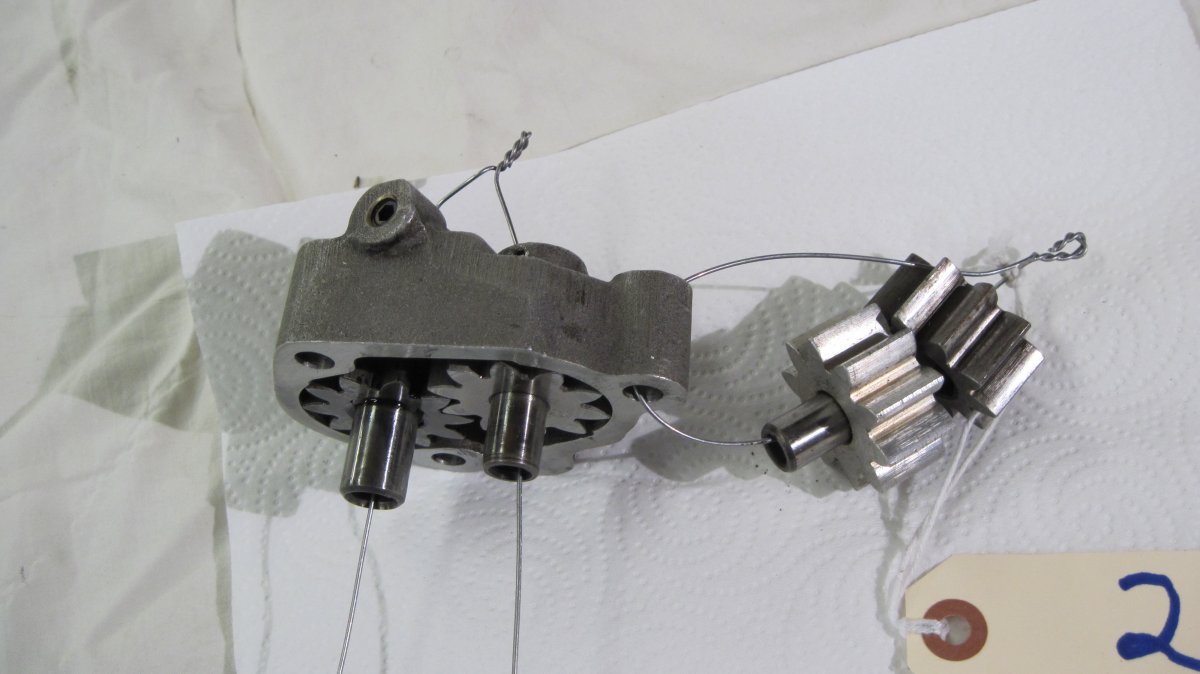
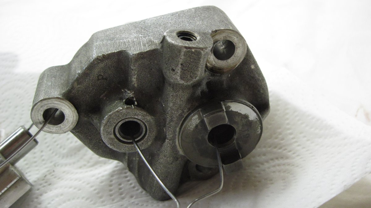
The Exhibit
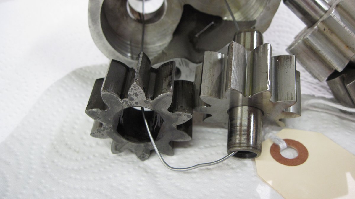
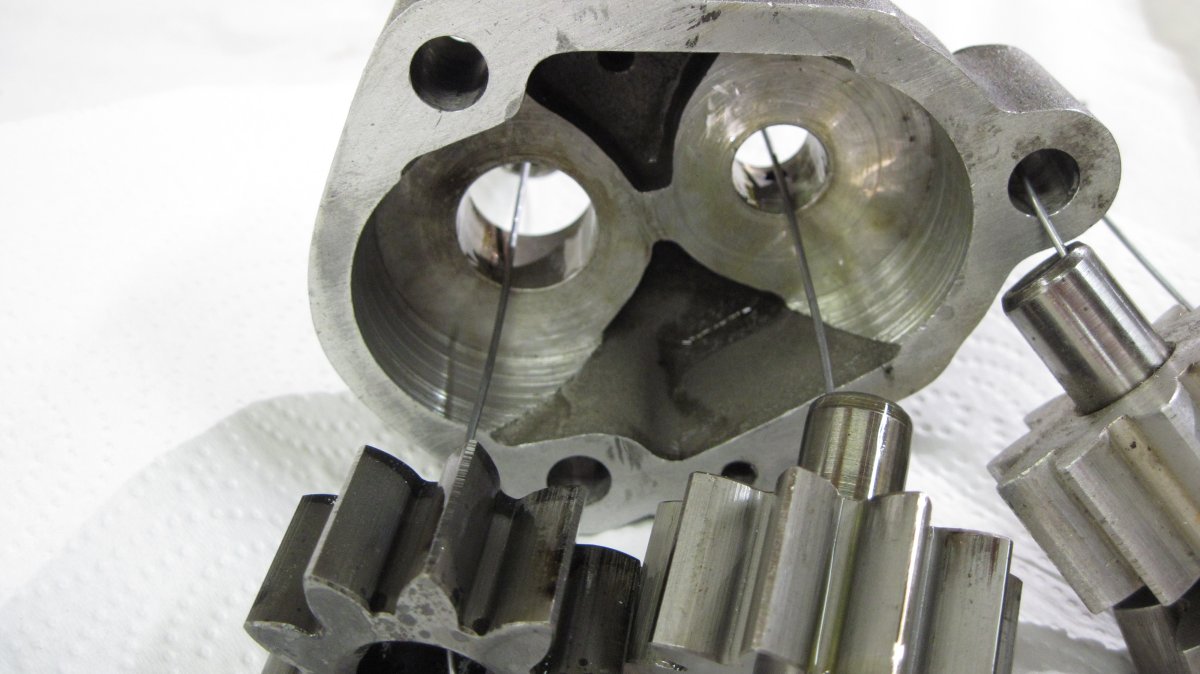
Exhibit 2 shows a Lycoming oil pump with acceptable and not acceptable part designs. The acceptable ones are assembled into the pump, while the unacceptable ones are wired through a mounting hole. The acceptable ones are aftermarket versions of Lycoming PNs LW-18109 and LW-18110 that were removed from service during an engine overhaul. The unacceptable ones are Lycoming PNs 60746 used in combination with LW-13775.
References
FAA Advisory Circular 43-16A, Aviation Maintenance Alerts, Alert Number 272, March 2001.
FAA Advisory Circular 43-16A, Aviation Maintenance Alerts, Alert Number 275, June 2001.
FAA Airworthiness Directive 75-08-09, July 9, 1975.
FAA Airworthiness Directive 81-18-04 R2, June 7, 1982.
FAA Airworthiness Directive 96-09-10, July 15, 1996.
Lycoming Direct Drive Overhaul Manual, 1974.
Lycoming Numerical Parts History, SSP-449A.
Lycoming Parts Catalogs PC-111, PC-102, PC-103, PC-106, PC-110, PC-114, PC-115-3, PC-119, PC-202-1, PC-206, PC-302 and PC-406-1.
Lycoming Service Bulletin No. 381B.
Lycoming Service Bulletin No. 385C.
Lycoming Service Bulletin No. 454B.
Lycoming Service Bulletin No. 455D.
Lycoming Service Bulletin No. 456F.
Lycoming Service Bulletin No. 524.
Lycoming Service Instruction No. 1230B.
Lycoming Service Instruction No. 1272.
 |
 |
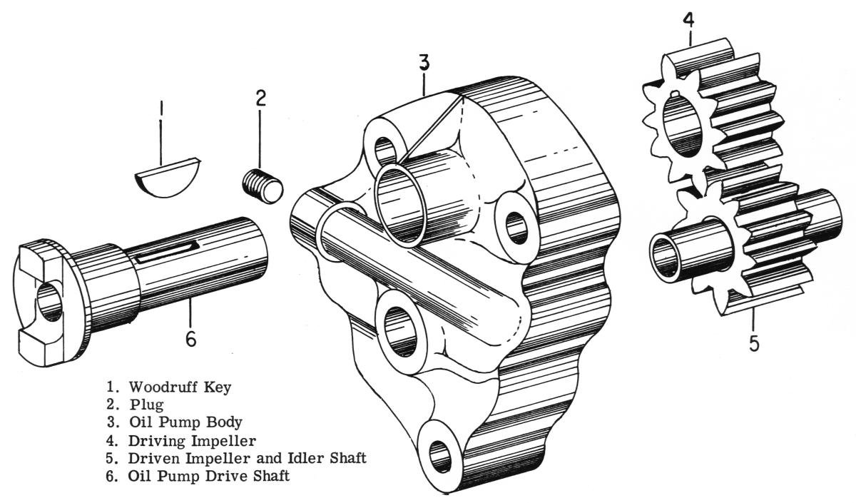 |
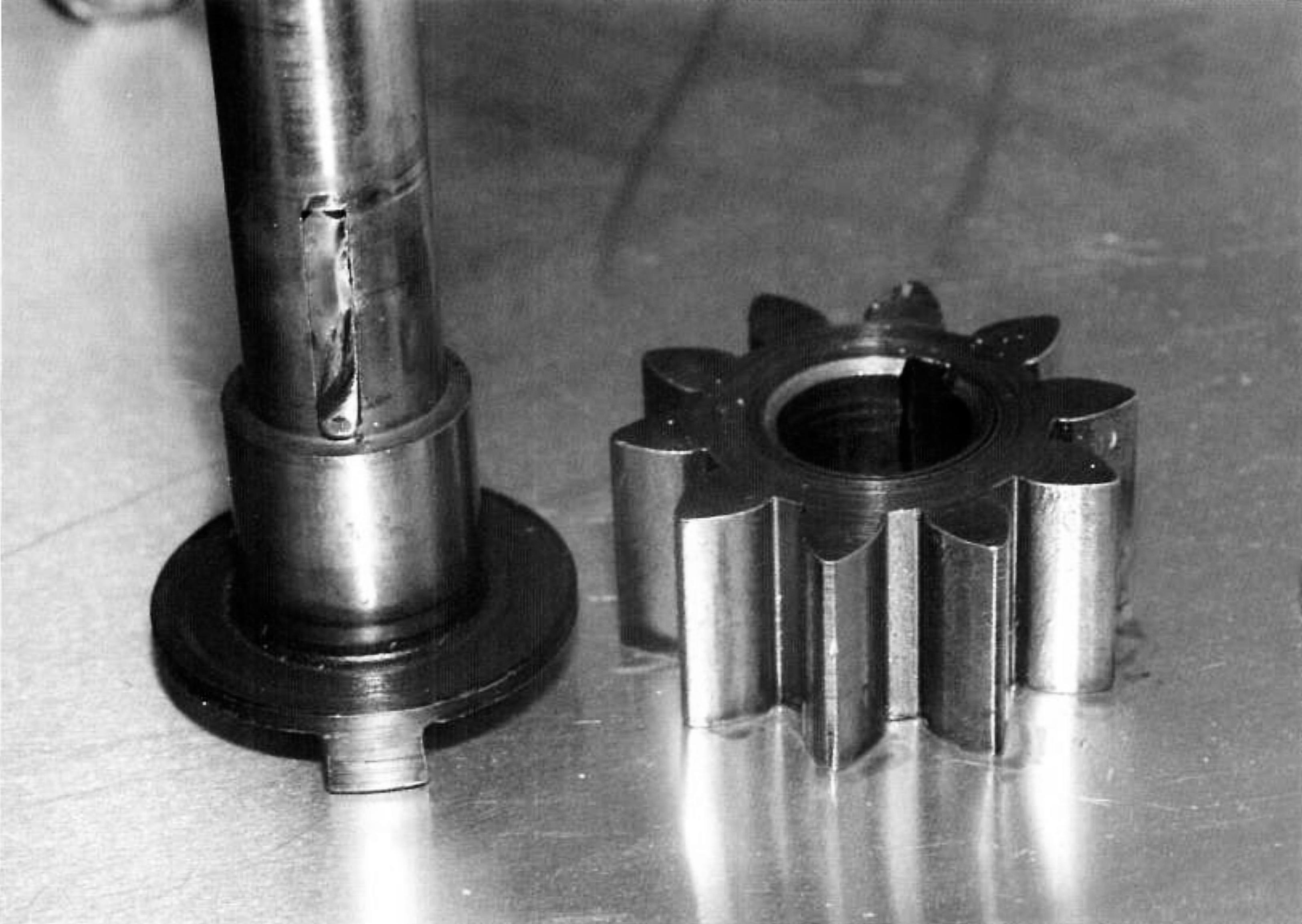 |
| Lycoming Oil Pump Components | Original Lycoming Oil Pump Design. One-piece body (bottom) replaced two-piece body (top). | Sintered Iron Impellers with Woodruff Key Drive | Failed Woodruff Key Drive |
 |
 |
 |
 |
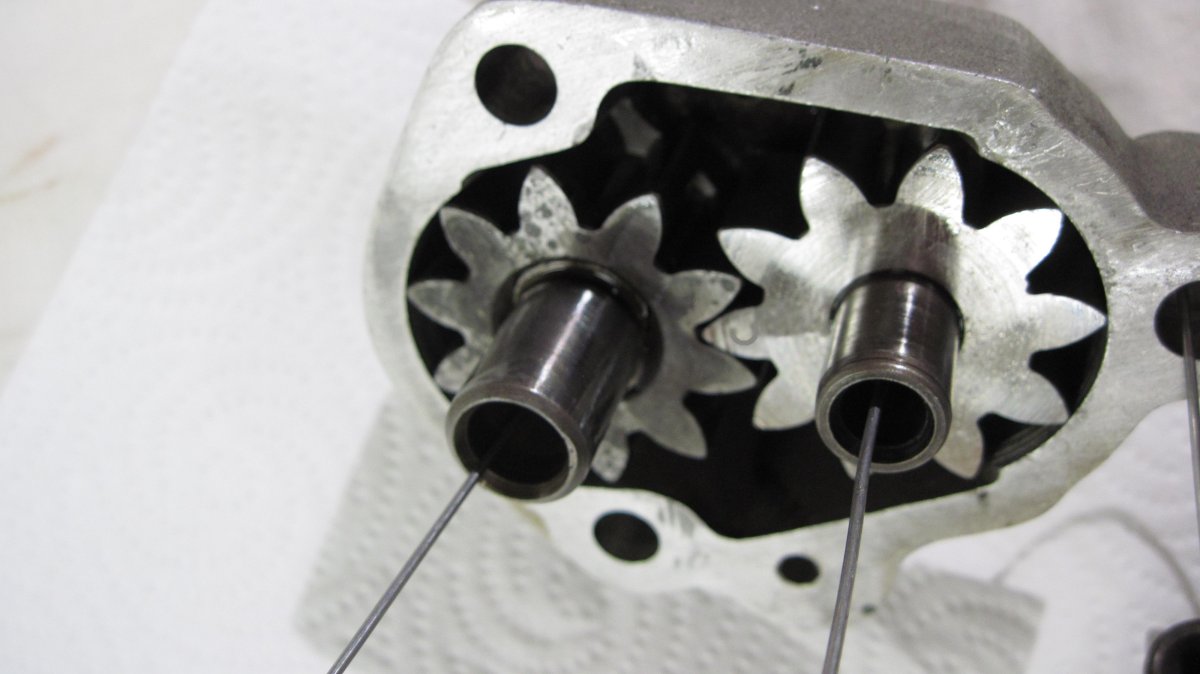
| Double-D Oil Pump Drive Shaft and Drive Impeller | Four-Cylinder Oil Pump Assembly | Hardened Impellers Assembled in Oil Pump Body. The drive impeller (left) is nitrided and marked with an "N"; the driven impeller assembly (right) is carburized and marked with a "C". | PN 61174 Oil Pump Drive Shaft |
 |
 |
 |
|
| Hardened Steel Impellers Removed from Body | Oil Pump Body Interior. Scratches are typical of an oil pump at overhaul. | PN LW-13775 Aluminum Driven Impeller Assembly (center) and PN 60746 Steel Drive Impeller (right). If found, these parts must be replaced. |
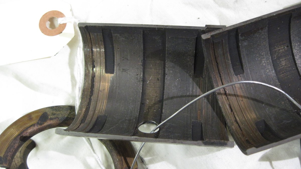
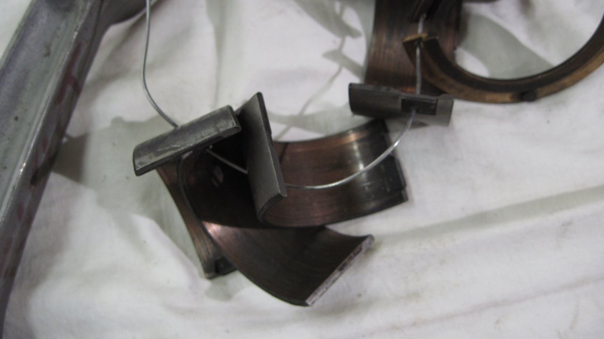
Exhibit 8 – Worn Bearings and Defective Connecting Rod
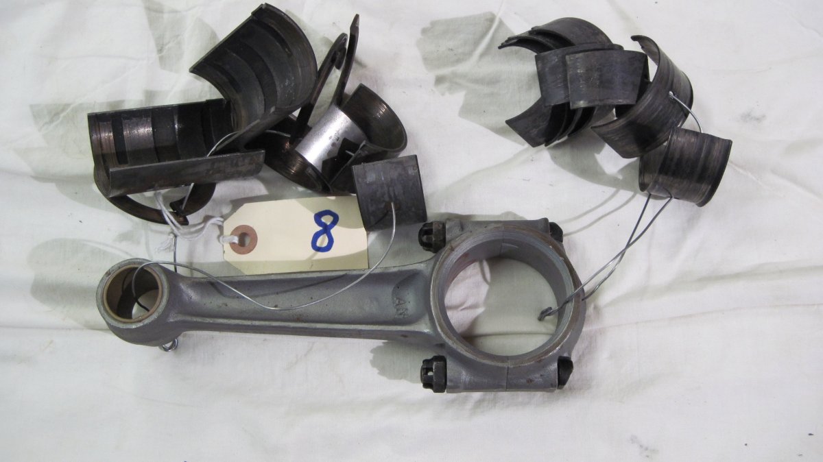
These parts were removed from a Continental C75. The pilot noticed high oil temperature, followed by falling oil pressure and a knocking noise from the engine. He landed at the nearest airport, which was a good thing, because the engine was minutes away from complete failure.
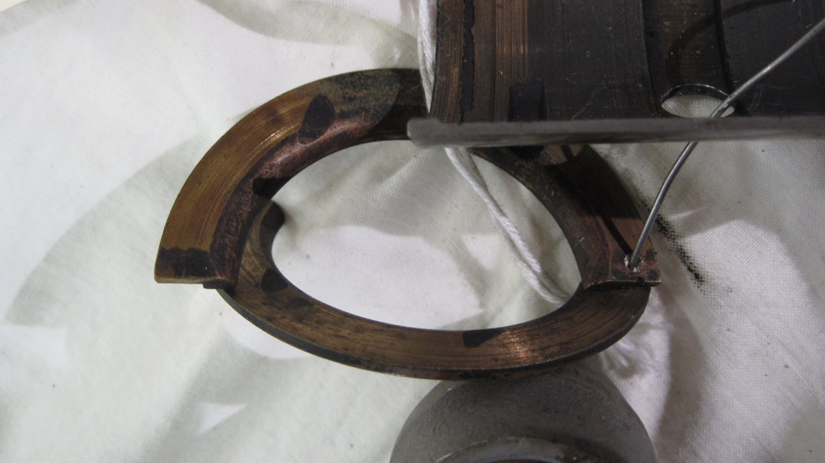
All bearings were worn as can be seen by comparing them with the practically new bearings show in Exhibit 3. These were all tri-metal bearings, with a steel shell, copper-lead bearing surface, and Babbitt flash. When new, they looked like the ones in Exhibit 3. All are severely worn, as evidenced by the copper color and scratches. The #1 connecting rod bearing would have soon failed catastrophically.
 |
 |
 |
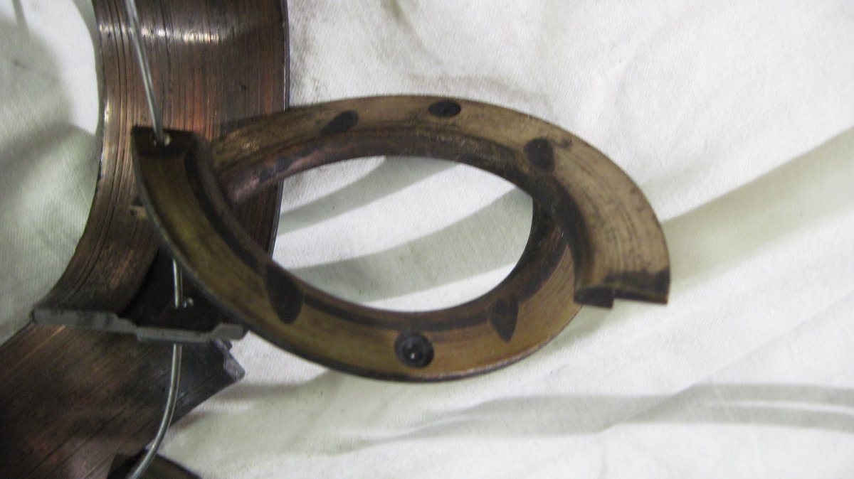 |
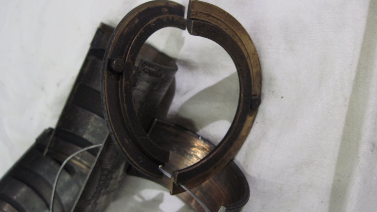
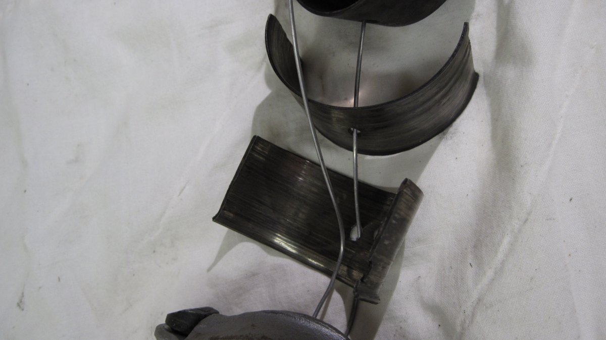
| Main Bearings (top right), Rod Bearings (top left) and Connecting Rod (bottom) | Front Main Bearing. Note Worn and Scratched Areas Fore and Aft. | Front Main Bearing Front Thrust Washers. Holes were drilled in the corners to keep thrust washers with the exhibit. | Front Main Bearing Aft Thrust Washers. |
 |
 |
 |
 |
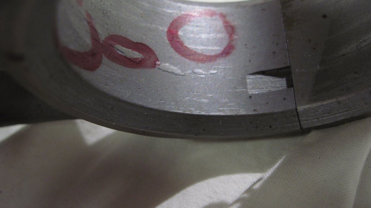
| Front Side of Aft Thrust Washer Showing Locating Pins. These prevent the thrust washers from rotating in the crankcase. | Worn Main Bearings | Connecting Rod # 1, Damaged Beyond Repair. Circles Indicate Galled Spots. | Bearings from Rod # 1. The copper-lead is almost completely gone and the steel shells have extruded out of the rod big end. |
 |
 |
 |
 |
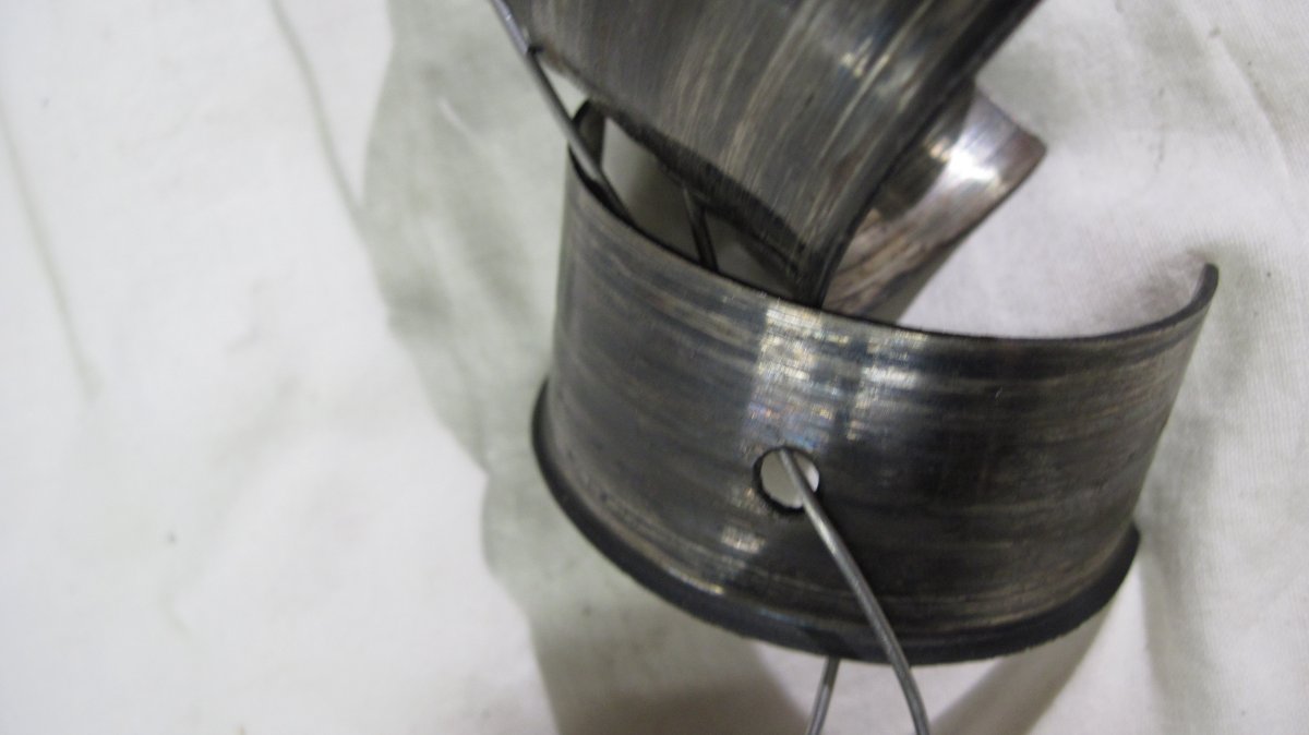
| Another View of # 1 Connecting Rod Bearing | Another View of # 1 Connecting Rod Bearing | Connecting Rod Bearings # 2, #, 3 and # 4 | Comparison of #1 with the Other Rod Bearings |
Send mail to
![]() with questions or comments about this web site.
with questions or comments about this web site.
![]()