(A.V.T. = Aero Vertical Twin)
Carburetion
| This feature was excerpted from Carburetion as Applied to Bristol Aero Engines, published in 1943. Thanks to Bruce Vander Mark for scanning and the use of this material. The full manual is available from Mach One Manuals |
Introduction
Internal combustion engines, as the name implies, obtain their heat energy, which is the source of power, from the combustion in the cylinders of a mixture of fuel vapor and air. The engine operates by virtue of the high pressures caused by the rapidly increased temperatures accompanying combustion; the ensuing expansion of the gases forces the piston downwards during the power stroke. There is no "explosion", as usually understood, in the cylinders of an engine that is operating correctly. The cycle is: induction, compression, ignition and expansion, exhaust.
The term "carburetion", as applied to the internal combustion engine, implies the furnishing of a combustible mixture of fuel-vapor and air in certain proportions according to the requirements of the engine at any moment. The fuels consist chiefly of carbon and hydrogen combined in a form known chemically as hydrocarbon. The proportions are roughly 85% carbon to 14% hydrogen, the balance consisting of less important organic impurities. Air is composed mainly of oxygen and nitrogen roughly in the weight proportions of 23% to 77% the mere traces of other gases being negligible. The active bodies in the process of combustion are the carbon and hydrogen of the fuel and the oxygen of the air. Nitrogen is an inert gas and during the-engine cycle enters the cylinders with the oxygen, is compressed, heated and expelled without any chemical change taking place. However, it performs an important function in that it tempers the explosion that would occur if oxygen alone was used into a controlled combustion, enabling the relatively slow-moving mechanical parts of the engine to absorb the energy efficiently. Being inert, and thus passing unchanged through the combustion chambers of the engine, nitrogen makes a valuable contribution to the maintenance of reasonable temperatures.
The proportion of fuel to air is vitally important and when discussing the subject there are three factors to be considered. These are, power, temperatures and economy. The chemically correct fuel:air ratio to obtain complete combustion (that is, when all the carbon, hydrogen and oxygen are consumed, leaving a residue of water vapor and carbon-dioxide), is about 1:15 by weight for average petrols. But there are two features that preclude the use of-the "chemically correct" mixture. Firstly, complete combustion does not give maximum efficiency owing to a phenomenon known as dissociation, which takes place at the high temperatures attained. This is a momentary splitting-up of the products of combustion into their component parts which absorbs heat thus leaving less for external work. Recombination takes place later in the expansion, after the main effect of the combustion has passed. Secondly, there is a possibility of detonation, an undesirable condition that will be explained more fully later. It is sufficient at this juncture to state that detonation is a sharp localized explosion in the cylinder, which results in great loss of power and a dangerous increase in temperature if allowed to persist. It has been found experimentally that maximum heat energy with safe temperatures is available, and the danger of detonation avoided, by the combustion of a mixture at least 10% richer than that "theoretically correct" since this reduces the temperatures below that at which dissociation occurs.
Engine power is a product of RPM and the average pressures attained in the cylinders during one cycle of the engine (MEP). High power conditions are obtained by increasing either or both, but in the process the temperature of the mixture is increased., with consequent tendency to detonation. This can be corrected by providing an even richer mixture at the high power settings. The extra petrol gives a "wet" induction, the subsequent evaporation of which absorbs heat from the air. This produces a marked cooling effect and. thereby reduces the danger of high temperature effects.
Heat is dependent on the amount of oxygen present in the mixture. The temperatures attained with the mixture giving maximum safe heat energy, that is, at least 10% richer than "correct", can be coped with. But as the proportion of fuel to air is reduced, temperatures rise, until when the mixture is about 8% richer than "correct", a position known as the Weakest Mixture for Maximum Power (WMMP) is reached. The temperatures around tins point are definitely detrimental to the mechanical efficiency of the engine and it is a condition that must be avoided. Consequently, on Bristol engines, the mixture used for normal cruising powers is about 7% richer than that at the WMMP position that is about 15% richer than "theoretically correct".
With further weakening from the WMMP position, the rate of, combustion is slower, because of the greater proportion of nitrogen in the mixture, which causes a falling off in power. Assuming that compression ratios, etc., remain unchanged, for a given mixture strength, the rate of combustion remains constant. There is a definite period of time involved. When the mixture strength is reduced and combustion slows up, there is a power loss due to piston movement. For a given RPM the slower the combustion the farther the piston will have traveled down the cylinder and the later and lower will be the peak pressures reached in the cylinders. Thus average pressures (MEP) will be lower. If the process of weakening is continued not only does power continue to fall but temperatures decrease because less oxygen is necessary to complete the combustion of the smaller quantity of fuel (the excess oxygen being expelled through the exhaust) and the chemical action is less. Again, since the combustion is taking place during the expansion stroke, the lowered pressures result in decreased temperatures. As a last small factor, an increasing area of cylinder wall is exposed by piston movement as potential cooling area. When the fuel:air ratio has fallen to 1:20, combustion may still be taking place even when the inlet valves are opening, and the ignition of the incoming mixture causes "popping back" in the carburretter.
A richer mixture than "correct" is desirable at slow running for several reasons. These include assistance in starting from cold, and to obtain regular firing under conditions peculiar to slow running, such as a larger proportion of exhaust gases left in the cylinders, a reduction in the efficiency of mixture distribution and the considerable effect of valve timing at low RPM In addition, the richer mixture is desirable so that the sudden increased airflow when opening up does not "dry up" the induction system to a state of weakness on which the engine will not run.
The sequence of mixture strengths through the engine operating range is therefore, very rich at slow running, weakening to about 15% above "correct" for the normal cruising range, enrichment to approximately 22% above "correct" for rated power, and further enrichment to 28% for takeoff power. Over the cruising range it is desirable to have an alternative weaker mixture on the score of fuel economy. Advantage is therefore taken of the drop in temperature with weakening-off past the WMMP position to obtain a lower fuel flow for the same air weight. By this means, a mixture some 8% weaker than "correct" gives economy with safe temperatures for relatively small loss of power. This is known as Economical Cruising mixture strength. The corresponding fuel:air ratios over the range are: Take-off, 1:10; Rated, 1:11; Normal Cruising, 1:12; and Economical Cruising, 1:16.
Carburetter Operation
Now it remains to see how the carburetter functions, how the various mixture strengths are obtained and to examine briefly the requirements peculiar to the units employed on aero-engines.
|
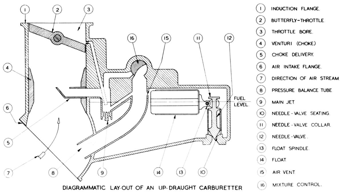
| Fig. 1. Simplified Cross Section of a Claudel-Hobson A.V.T 85E Carburettor (A.V.T. = Aero Vertical Twin) |
Figure 1 shows, in simplified form, the essentials of an aero-engine carburetter. Liquid fuel must first be metered to the required fuel:air ratio and the airstream into the engine then distributed in such a manner as to ensure as uniform a distribution of the fuel as possible so as to produce a homogeneous mixture. The Claudel-Hobson float-type of carburetter used on Bristol engines employs the principle of pressure difference to obtain this end.
Now a certain mass of air moving through a passage at a given speed contains a constant amount of energy. If the area of the passage is reduced at one point, and the same mass of air caused to flow through it in the same space of time, its speed past the restriction will be increased. Since it is impossible to obtain something for nothing, the increase in velocity is obtained at the cost of a decrease in pressure. The total energy is the sane but its characteristics have changed. It is precisely this relationship between velocity and pressure that underlies the control of fuel flow to the engine. It can be seen from the illustration that such a restriction or venturi called the choke-tube is fitted in the air passage of the carburetter and that the jet outlet, (otherwise known as the choke delivery), is situated at that section of its throat where the velocity of the air-stream is greatest and therefore the pressure is lowest.
When the engine is idle the pressure, both in the choke and above the fuel in the float chamber, is equal and is that of atmosphere, since the float chamber is balanced to the air intake below the choke. But when the engine is running, the velocity of the air passing through the choke tube to the engine causes the pressure to fall below that above the fuel in the float chamber, and a flow of fuel through the metering jet to the region of lowest pressure takes place. This issues from the choke delivery in a finely divided spray. The pressure drop in the choke tube bears a fixed relation to the miss airflow through the choke, so that changes in the air demand of the engine according to the various throttled power conditions will produce their own appropriate changes in fuel-flow.
Now the flow characteristics of air and fuel differ, so that as the volume of air entering the engine increases there is a tendency for the proportion of fuel to increase, thus giving a richening-up effect. A diffuser is fitted to correct this tendency and Figure 1 shows its simplest form. The main jet is below the fuel level and when the engine is stationary fuel flows through it and rises to the level of that in the float chamber. The diffuser passage connects the pressure balance tube to a position below this level of fuel. When the engine is running, the amount of fuel above the jet is controlled by the air velocity through the chokes. As the level of fuel falls and the diffuser passage is uncovered the depression (suction) over the jet will be reduced progressively, thus maintaining the correct fuel:air ratio. Figure 2 shows the type of diffuser employed in the Claudel-Hobson A.V.T. 85 E. carburetter, which also assists in atomizing the fuel.
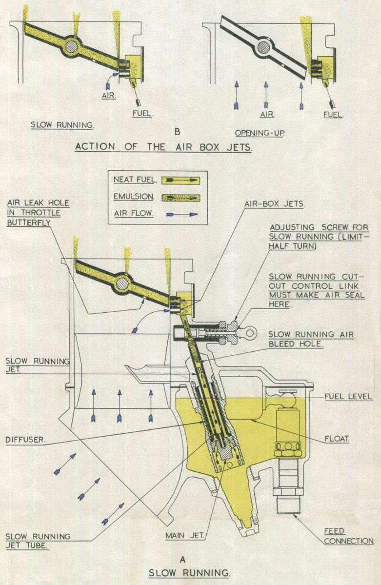
Slow-Running Circuit
The power developed by an engine depends largely on the weight of mixture burnt in the cylinders, and this is controlled by throttle butterfly position. Under full throttle conditions the pressure in the induction system is at a maximum and the region of lowest pressure throughout the system is in the throat of the choke tube. With the butterfly nearly closed, the volume of air passing into the engine is so small that the pressure below the butterfly rises to nearly that of atmosphere, and at the correspondingly low RPM there is insufficient depression to cause fuel to flow from the jet. The demands of the engine however lower the pressure in the induction system above the butterfly, (on up draught type of carburetter) and this is utilised to effect a second source of fuel supply especially for slow running conditions.
A slow running jet and passage are therefore provided having their outlet above or in line with the butterfly when it is in the slow-running position. Some means of assisting in fuel atomization, such as an air bleed is usually incorporated together with a simple method of adjusting the amount or quality of the supply.
 |
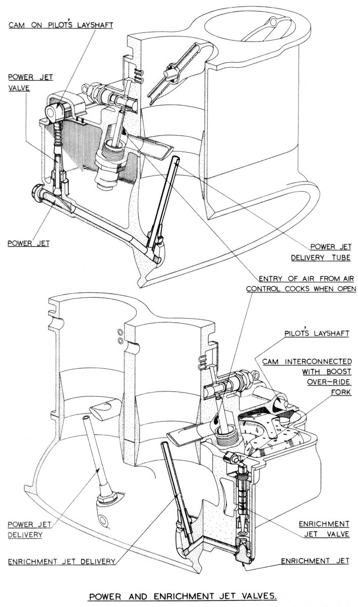 |
| Fig. 2. Slow Running Circuit Details | Fig. 3. Power and Enrichment Jets |
Power and Enrichment Jets
In order to supply the extra fuel necessary for the high power conditions, additional jets controlled by mechanically operated valves are employed. Thus when rated power is used a jet known as the power jet is brought into operation, whilst for the still higher take-off power the enrichment jet supplements the power jet. These jets are not included in Figure 1 for reasons of clarity, but do appear in Figure 3.
So much for the metering function of the carburetter. Before discussing the remaining requirements of an aero-engine carburetter, it is advisable to consider the behavior of the combustible fuel:air mixture in its ultimate conversion to mechanical power. It has already been pointed out that besides metering the fuel, the carburetter acts as an elementary atomizer; that is, the depression, the relatively high velocity conditions at the choke, and the action of the diffuser cause the liquid fuel to be broken up into small globules. A fuel:air mist therefore passes into the supercharger where it is whirled into a more nearly homogeneous mixture, raised in pressure, and distributed to the cylinders. The profile design of the carburetter, supercharger entry, volute casing, impeller, diffuser vanes, and induction pipes to the cylinders all contribute their quota to governing the quality and homogeneity of the combustible mixture in the cylinder.
Once in the cylinders, the combustion characteristics for a particular mixture strength are governed by the combustion chamber shape, spark plug location and the compression ratio. The last item is the ratio of gas volumes in the cylinder when the piston is at the bottom of its stroke to that when at the top, and for petrol engines is generally between 5 and 7 to 1. The compression ratio employed has a marked effect on combustion efficiency. It must be high enough to obtain maximum power (peak pressure) from the subsequent combustion, yet not so high as to raise the mixture temperature to the self-ignition point of the fuel or pre-ignition will take place before the plug fires, giving inefficient running. Excessively high compression ratios, and/or poor cylinder head design can also cause uneven mixture distribution and subsequent local high temperature` regions, which will produce detonation or "pinking" as it is commonly known.
When detonation occurs, initial combustion is quite normal. A small portion of the mixture near the spark plug is ignited first, and the resultant flame front moves across the cylinder, heating and compressing the rest of the charge. The nature of combustion suddenly changes and the last part of the mixture burns with explosive violence, producing a sharp ringing sound on the metal. This is not always audible among the noises of the engine and propeller, but is generally indicated by puffs of black smoke from the exhaust. The excessive cylinder pressures reached when detonation occurs subjects the engine mechanism to severe stresses, whilst the temperature of the engine parts, especially the spark plugs shows a sharp rise. Thus there is a loss in power, and mechanical wear is promoted.
Detonation must not be confused with pre-ignition; each results in a metallic knock, but detonation occurs after the intentional ignition of the charge whereas pre-ignition is caused by excessive compression ratios, the incandescence of some prominent projection, or excessive carbon deposit that ignites the charge before the actual ignition spark occurs.
Having considered the metering of the fuel and the behavior of the mixture in the cylinders, it is necessary to discuss briefly the refinements which are incorporated in the carburetter to cope with the requirements peculiar to aero-engines in operation.
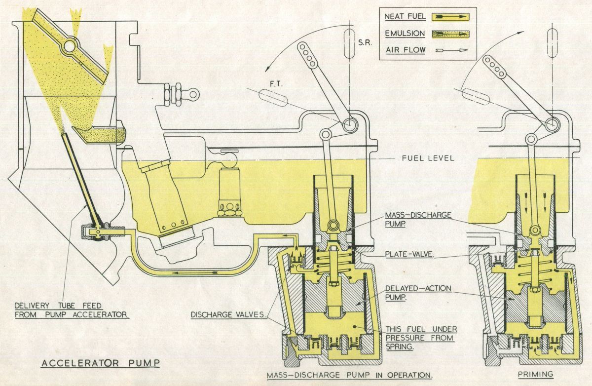
Accelerator Pump
Acceleration is of the utmost importance. Rapid opening-up, and the corresponding increase in the speed of the supercharger, causes fuel to be thrown out of suspension in the air stream and deposited on the walls of the supercharger. The resultant weakness is overcome by the incorporation of an accelerator pump that discharges a jet of fuel into the choke tube in two stages. This unit comprises two pumps in tandem; the upper, or mass-discharge pump responds directly to movement of the pilot's throttle lever, whilst the lower, or delayed action pump, is actuated by a spring imprisoned between the pistons of the two pumps. The fuel from the mass-discharge pump replaces that thrown out of suspension, and the delayed-action pump gives a timed discharge to enrichen the mixture to the strength necessary for good acceleration.
Mixture Control
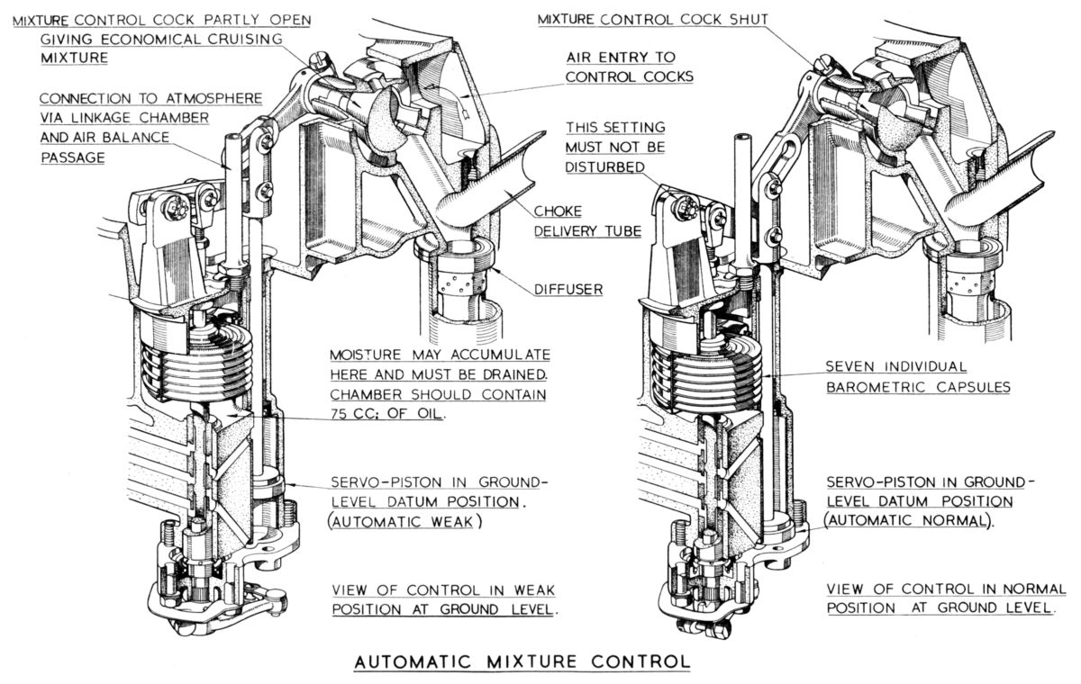
With increase in altitude the air density or weight per unit volume becomes less, decreasing regularly and in a fixed relation to the altitude. This means that to get the same amount of air into the engine for a given setting and at ground level, the throttle butterflies must be wider open and the air velocity through the chokes considerably higher. The result is that the fuel metering pressure, which depends on velocity, is higher and the mixture therefore richer. It is essential that the required mixture strengths for the powers employed should be maintained at all operating altitudes. To counteract this enriching effect, the mixture control valve is operated to permit a controlled quantity of air from the pressure balance system to enter the main jet passages into the choke delivery without entering the diffuser. This partially breaks down the pressure drop causing fuel flow and gives a reduced flow sufficient to maintain the selected mixture strength with increase in altitude. The mixture control valve is closed at ground level, and is calibrated so that a gradually increased opening with increase in altitude keeps the metered fuel, and hence the mixture strength, constant.
 |
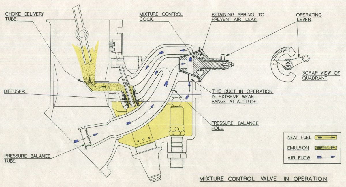 |
| Fig. 4. Accelerator Pump Operation | Fig. 5. Mixture Control Operation |
Boost Control
It is impossible to consider carburation as applied to Bristol engines without further reference to the supercharger. Its delivery pressure (boost) is governed by the action of the boost control unit, which consists of a small servo piston in its cylinder, the operating oil being controlled by a sliding valve and a pressure sensitive aneroid. The aneroid is situated in a chamber that is open only to the pressure in the induction system, and has a variable location at its upper end, the valve being attached to the lower end of the aneroid. Variation in the induction pressure causes the aneroid to expand or contract and so to move the valve down or up, allowing oil to flow below or above the servo piston. The piston motion is transmitted to the throttle butterflies, by the jointed piston rod of the boost control which is interconnected with the pilot's lever as illustrated in Figure 6. From this diagram it can be seen that if the piston is held stationary at the top of its stroke, movement of the pilot's throttle lever is reproduced in the throttle butterfly. Conversely, if the pilot's lever is locked, movement of the boost control piston in a downwards direction will close the throttle butterfly and subsequent upward movement will open it.
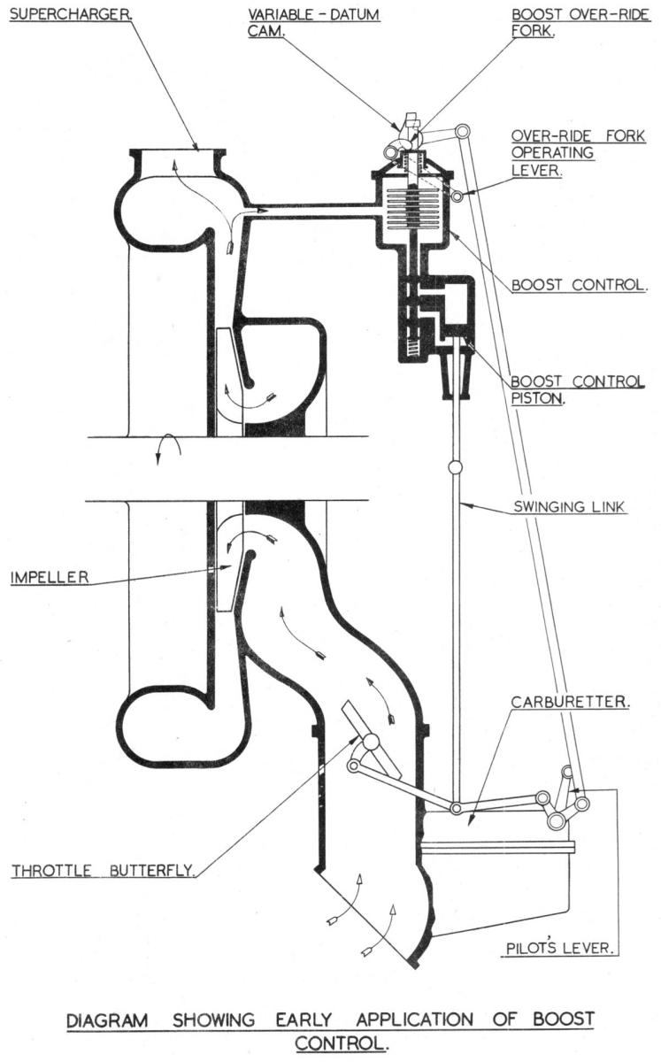 |
| Fig. 6. Bristol Boost Control Scheme |
The operation of a boost control is as follows. When an engine is stationary the pressure in the induction system is the same as that of the atmosphere, but when the engine is started it falls to some negative figure. The aneroid reacts by expanding thereby lowering the valve and directing oil beneath the servo-piston which moves to the top of its stroke. Subsequent throttle opening is accompanied by an increase in the induction pressure, which reaches a figure that will compress the aneroid, raising the valve and re-directing oil above the piston. The piston moves down the cylinder, closing the butterfly and reducing the induction pressure. As soon as this begins to fall below that at which the control is set to govern, the aneroid again expands. Thus the aneroid and valve will take up an equilibrium position and the servo-piston will be at some intermediate position in the cylinder. When climbing to altitude, the tendency for the induction pressure to fall is counteracted by the action of the boost control until height is reached where the butterflies are fully open. This is the rated altitude for that specific pressure. Above this height the control is inoperative, but if RPM are caused to rise, as in a dive, the boost control will intervene and close the butterfly the required amount to maintain the pressure.
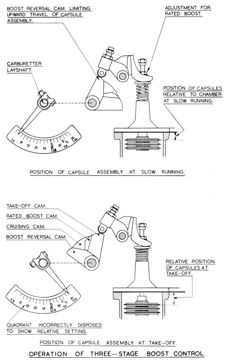
A little thought will show that. If the capsules are lowered bodily in their chamber a greater pressure will be required to compress them to a length where the valve is in, a neutral or equilibrium position. Therefore, by adjusting the capsule stack in the chamber, control of induction pressure can be varied as desired. Thus, in practice, with the pilot’s throttle lever fully open, the position of the capsule assembly is adjusted by means of its securing screw and locknut until the rated pressure is obtained. Fitted to the top of units, and interconnected with the pilot's throttle lever, is a cam with a profile that permits the aneroid assembly to rise in its chamber as the throttle lever is closed. The cam therefore progressively resets the boost control as the throttle lever is moved forward or backward, and for any position of the throttle lever a corresponding degree of boost will be given and maintained up to an altitude dependent on the pressure selected.
Later developments of this and other controls are illustrated in Figures 7 through 10.
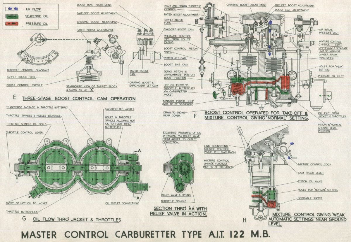 |
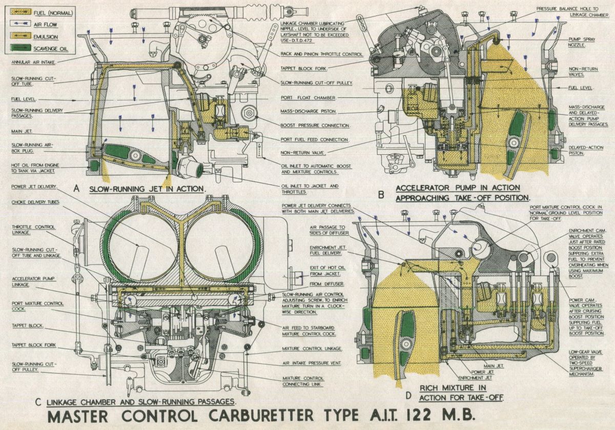 |
| Fig. 7. | Fig. 8. |
 |
 |
| Fig. 9. | Fig. 10. |
Cruise Control
Hitherto, the propeller has not been considered, and when RPM have been mentioned it has been assumed that a fixed-pitch propeller has been fitted to the engine. However, there are very few aircraft today that do not embody some form of controllable-pitch propeller that maintain a constant speed by automatic adjustment of their blade angle. Within a comparatively wide range the pilot can select the speed required. Now the higher the RPM selected, the greater will be the power output for a given boost pressure. Engine manufacturers therefore always include in the performance limitations of an engine the maximum RPM for certain boost pressures. Power can therefore be varied by means of the propeller control lever as well as the throttle lever. Both methods are permissible but the effects on the engine differ considerably.
In engine operation, there are two definite stages of high power output (rated and take-off) and a range of powers available for cruising. For high-power conditions the maximum permissible boost and RPM are usually employed, but most flying is carried out in the cruising range in weak mixture, and the chief consideration is economy. For specified aircraft the cruising indicated air speed (IAS) giving maximum Air Miles per Gallon (AMPG) for various loads are established by flight tests, and once established it remains to obtain the IAS as economically as possible. The power necessary to give the speed may be obtained by various combinations of boost and RPM Two factors affect fuel consumption; the power necessary to drive the supercharger, and the volume of mixture consumed in the engine. If the power is obtained by selecting nearly the maximum permissible boost and the RPM is lowered, minimum power is absorbed by the supercharger and the volume of mixture consumed is the minimum, for the required power. In addition the mixture is cooler at the lower supercharger speed. The result — maximum AMPG On the other hand, if high RPM are employed and the required power is obtained by reducing boost, the supercharger absorbs more power and is working inefficiently. At the high speed, the volume of mixture consumed increases, giving a higher fuel consumption. The supercharger could give the required boost at a lower speed, so power is being wasted. Further, the power necessary for the required IAS must still be transmitted to the propeller, so that a relatively higher RPM is required to compensate for power wasted in the supercharger.
The "high boost - low rev" rule should therefore always be applied when cruising in the weak mixture position. When maximum endurance rather than maximum cruising range is required, the RPM and boost should be reduced until the lowest IAS compatible with comfortable flying is obtained.
Carburetter Freezing
Ice formation in the carburetter is perhaps more dangerous than on the wings of am aircraft since on the wings it can be observed, but if it forms on the carburetter the pilot's first indication is a loss of power. Ice generally affects the power a very short time after it is formed, and it may cut out the engine completely unless immediate action is taken. Familiarity with the conditions that cause freezing and the symptoms of its effect on the engine is therefore advisable. When freezing has once caused severe loss of power it is almost impossible to check further ice formation, even when special de-icing equipment other than heat is available. Carburetter freezing usually takes place owing to formation of ice in the choke area or to the accumulation of ice and snow in the air intake and air balance system.
Ice formation in the choke area is basically due to temperature changes in the carburetter and these are inseparable from its operation. Both the pressure drop in the choke tube and the vaporization of fuel contribute to a drop in the air temperature as it passes through the carburetter. Vaporization of the fuel is the chief cause, and the reduction in temperature always exists when the engine is running. The degree is dependent on the fuel:air ratio. In order to vaporize the fuel, heat is taken from the air passing through the chokes, and from this cause a drop of as much as 20°C may result. The total temperature drop from this, reduction in pressure, and also vaporizing any moisture in the air, can amount in extreme cases to 30°C; and it is possible even in summer to have a temperature in the carburetter as low as 0°C, If at the same time the atmosphere has a high relative humidity, or if flying through cloud or rain, formation of ice will take place In these circumstances the reasons are apparent, but ice can also form when the atmosphere is clear.
Air can retain moisture in the form of water vapor, the maximum quantity at any given temperature being known as a relative humidity of 100%. The higher the temperature of the air, the more vapor it can retain Thus when air at 40°C and air at 10°C both have a relative humidity of 100% that at the higher temperature contains a larger quantity of vapor; but if this air is cooled, the moisture in excess of the amount it can then contain is condensed out as free water. As this water passes through the chokes some of it will be deposited on the chokes and throttles and will freeze at the critical temperature. Rain naturally increases the amount of free water and so accelerates ice formation.
The ice so formed may cause a reduction in choke area, partial obstruction of the fuel outlets, or even jamming of the throttle, any or all of which can have serious results. The position of ice deposit can be roughly assessed by the engine reaction. Ice on the butterflies will have the same effect as slowly closing them. The boost pressure gradually falls, although if the engine is fitted with a constant-speed propeller the RPM may remain constant for a time. Owing to ice breaking away from time to time boost fluctuation may accompany the drop in pressure. In conditions of incipient freezing, it is inadvisable to use small throttle openings If, on the other hand, ice has formed in the chokes or round the fuel outlets the mixture may become either too weak or too rich according to the type of ice formation. Either causes a reduction in power, but richness may be indicated by black smoke from the exhaust.
Icing up around the air intake and pressure balance system is due to the presence in the air of snow or moisture that is already partially freezing. When this collects in the air intake, similar accumulations are visible on the wings of the aircraft. The effects on the engine will be a loss of power which is accompanied by extreme richness if ice also blocks the air-balance passages.
There are two principle methods at present used to prevent freezing. Firstly by raising the temperature of the ingoing air to ensure that the temperature of the mixture does not fail within the freezing range; and secondly by supplying the mixture with a percentage of alcohol that is either mixed with the fuel or injected into the chokes when freezing is indicated. With regard to the former method, it is very important to appreciate that the temperature to be considered at all times is that of the mixture passing the chokes, which is roughly 15°C to 20°C below that of atmosphere. Thus it will be seen that in humid conditions ice may form in the carburetter even when atmospheric temperature is as high as 20 C, and under such conditions warm air should be used to avoid the freezing range at the chokes. Latest types of carburetters incorporate oil-heated throttle butterflies as shown in SD.189, and these are not subject to icing-up in the choke area.
Accumulations in the intake of impact ice and snow can be minimized by ice guards but where these are not fitted the use of warm air is the only solution. Unfortunately warm air increases the fuel consumption relatively by 7% and also reduces the volumetric efficiency of the engine. It should be understood that freezing occurs only in high relative humidity and that the carburetter functions satisfactorily in all other conditions. Cold air should always be employed provided that the aircraft is not operating at high boost pressures or flying either through cloud or humid atmosphere of about 20°C to a few degrees below zero.
Fuels
The fuels used in aero-engines are practically all derived from crude oils that are obtained from wells in different parts of the world. The nature of the crude varies with the place of origin. As obtained from the wells oil contains every variety of hydrocarbon, from thick tarry matter to gas that is blown off in large quantities. By a process of distillation or fractionating the crude oil is resolved into its various constituents based on different boiling points. The lighter fractions are employed in engines using a carburetter and are known as "volatile" fuels. The heavy fractions, the "non-volatiles" are used in diesels, and include the lubricating oils. These generally go through an additional process called "cracking", in which they are subjected to great heat under pressure which splits or "cracks" the large molecules into smaller ones that have lower boiling points. When mixed with "straight" spirits they are also used in internal combustion engines. All these liquid fuels are hydrocarbons. Each fuel differs from the other in the number and arrangement of the atoms in the molecule, and the difference in the arrangement divides the fuels into groups such as aromatics, paraffins, etc. Each group is then sub-divided according to the number of atoms in its molecule. Thus benzene is the smallest molecule in the aromatic group with six carbon atoms; whilst methane, the smallest of the paraffin group, has but one.
Normal fuels are a mixture, in various proportions, of the various groups, and are blended according to the purpose for which they are intended. In the same engine the tendency to detonate differs with the type of fuel used. Of the groups of volatile fuels, the paraffins show the greatest, and the aromatics the least tendency to detonate; whilst those known as unsaturateds occupy an intermediate position. Hence the higher proportion of aromatics the better the fuel. The tendency towards detonation increases as the engine compression ratio is increased, and it is also affected, as already stated, by spark plug position and cylinder-head design, etc., Research has established a critical compression ratio for each fuel, known as the "highest useful compression ratio”, by running single-cylinder variable-compression engines at full throttle and constant speed. This represents the limit of compression efficiency at which a fuel can be used and is closely linked with the octane-number scale.
The octane number of a particular fuel represents a measure of the compression at which it may be used, and thus its anti-knock or anti-detonation value. The adoption of this means of assessing the value of a fuel depends on the fact that pure iso-octane is an eminently good anti-knock fuel, although expensive to produce. The octane number of a fuel represents the percentage of iso-octane in a mixture of that fuel and heptane. Heptane is a notoriously bad fuel from the anti-knock-point of view. This mixture and the fuel to be classified are compared in the variable-compression engine as mentioned previously. Thus, an 87 octane fuel is equivalent to a mixture of 87% octane and 13% heptane, i.e. it has the same critical compression ratio.
Extreme purification of fuels to obtain a high octane value is extremely expensive and rather wasteful since "dopes" will make an ordinary fuel equivalent in effect to a purified high-percentage aromatic fuel. The addition of a few c.c.'s per gallon of tetra-ethyl lead or similar dopes raises the octane number of the fuels. As an indication of the proportions used, the amount added to aviation fuels varies between four and five cc's per gallon, although the fuel employed in the 1929 Schneider Trophy aeroplanes contained as much as 10 c.c.'s of tetra-ethyl lead per gallon of benzole.
Send mail to
![]() with questions or comments about this web site.
with questions or comments about this web site.
![]()